A ThyssenKrupp Technologies company - Rotek Inc Catalog_smallest.pdf · A ThyssenKrupp Technologies...
81
Transcript of A ThyssenKrupp Technologies company - Rotek Inc Catalog_smallest.pdf · A ThyssenKrupp Technologies...


Rotek IncorporatedA ThyssenKrupp Technologies company
Large-DiameterAnti-Friction Bearings
Rotek IncorporatedA ThyssenKrupp Technologies company
Rotek Incorporated1400 South Chillicothe RoadAurora, Ohio 44202Telephone: 330/562-4000Toll free: 1-800-221-8043Fax: (Sales) 330/562-4620Fax: (Engineering) 330/562-2709
Copyright ©2002, Rotek IncorporatedPrinted in U.S.A.
Large-DiameterAnti-Friction Bearings
Rotek IncorporatedA ThyssenKrupp Technologies company
Rotek Incorporated1400 South Chillicothe RoadAurora, Ohio 44202-9282Telephone: 330/562-4000Toll free: 1-800-221-8043Fax: (Sales) 330/562-4620Fax: (Engineering) 330/562-2709www.rotek-inc.com
Copyright ©2002, Rotek IncorporatedPrinted in U.S.A. — 2M-6/02
Wind turbine cover photo courtesy ofEnron.

Rotek: Your Best Source For Large-Diameter Bearings
Rotek Incorporated offers aunique combination of experi-ence and technology inlarge-diameter bearings.Since our founding in 1962,we’ve designed and manu-factured thousands of large-diameter bearings for awide range of applications.We pioneered big bearingtechnology for applications inpower cranes and excava-tors, military equipment,machine tools, medicalequipment, large antennas,wind turbines, and manyother applications.
We’ve complemented ourproduct expertise with a vari-ety of customer-orientedbusiness philosophies andtechniques. Our Total QualityManagement program andcontinuous improvement poli-cy have earned certificationto ISO 9001 and ISO 9002standards.
Our integrated manufacturingcapabilities - including astate-of-the-art ring rollingmill, heat treating facilities,complete machining facilities,and CNC/CAD/CAM tech-nologies - allow us to offerour customers a high-qualityproduct with shorter leadtimes and reliable deliveryschedules.
And, our customer servicesare extensive. Rotek offersexperienced application engi-neering assistance and com-plete, worldwide after-the-sale services, includinginstallation supervision, pre-ventative maintenance pro-grams, and in-use bearinganalysis. Rotek also offersrefurbishment and replace-ment programs for bearingswhich require removal fromservice.
This catalog will introduceyou to the broad range oflarge-diameter bearingsdesigned and manufacturedby Rotek Incorporated. It willprovide information that maybe used to determine whichRotek bearing model isappropriate for your applica-tion. Please feel free to con-tact us for any additionalinformation you may require,or to start the applicationengineering process.
Please note the following:
• Specifications and other information appearing in this catalog are subject to change without notice.
• Final selection of a bearing for any application must be reviewed and approved by
Rotek prior to ordering.• We suggest you read
through the entire engineering data section before you begin the process of selecting a bearing for your specific application. Doing so will familiarize you with all of the variables that should be considered in the selection process.
� This symbol is usedthroughout the catalog toremind you to call us fortechnical and applicationassistance, current produc-tion information, and relateddata. Call your Rotek SalesEngineer or the RotekApplication EngineeringDepartment at 330/562-4000or toll-free at 800/221-8043.
• Rotek also manufactures a complete line of seamless, engineered rolled rings, in diameters from 18 inches to 160 inches; axial lengths up to 20 inches;weights up to 9,000 pounds; and in profiles from simple rectangular cross sections to complex contours. Please contact our Ring Rolling Division for more information.
2
Rotek Incorporated
Rotek Incorporated
4 Overview of Rotek Incorporated
8 Product Line Summary
12 Engineering Data (with separate table of contents)
37 Design Worksheet
Description, Loads and Dimensional Data
for Specific Rotek Bearing Series:
40 Series 1000 Single Row Ball Bearings
42 Series 2100 Single Row Ball Bearings
49 Rotek Standard Pinions for Econo-Trak Bearings
50 Series 3000 Single Row Ball Bearings
58 Series 4000 Double Row Ball Bearings
60 Series 5000 Cross Roller Bearings
64 Series 6000 High Speed Ball Bearings
66 Series 7100 Single Row Ball Vertical Thrust Bearings
66 Series 8000 Single Row Ball Vertical Thrust Bearings
68 Series 10,000 Three Row Roller Bearings
72 Series 15,000 Wire RaceTM Bearings
76 Precision Bearings
Table of Contents 3
2 Rotek: Your Best Source For Large-Diameter Bearings
1 Title Page/Contact Information

Rotek Incorporated
Overview: Leaders in the Design andManufacture of Large-Diameter Bearings
Since its founding in 1962,Rotek Incorporated hasgrown to become one of theworld’s recognized leaders inlarge-diameter bearing technology.
The company pioneered boththe development of large-diameter bearings, and theirintroduction as a substitutefor king post, hook roller andother older techniques forcontrolling loads in rotationalapplications. Over the years,Rotek has introduced thelarge-diameter bearing to awide variety of applications,including power cranes andexcavators, machine tools,medical equipment, largeradar and radio telescopeantennas, and wind turbines.
Rotek engineers have alsobeen responsible for most ofthe product design innova-tions for large-diameter bear-ings, including the introduc-tion of offset raceways, wireinsert raceways, high speedbearings, and "quiet" bear-ings for medical applications.
Today, Rotek offers a diverseline of large-diameter bear-ings: ball and roller types insingle-row and multiple-rowconfigurations; with integralinternal or external gearing,or gearless models; diame-ters from 12 inches to 50feet; with a wide range ofcapacities, materials, andseals available. Many areavailable from stock or onshort lead times. Rotek’sdiverse product line makes itpossible to provide a large-diameter bearing that is mostappropriate for your application, on the most cost-effective basis possible.
4
5
Rotek Incorporated
Overview: Our Extensive Design ExperienceProvides Application Solutions
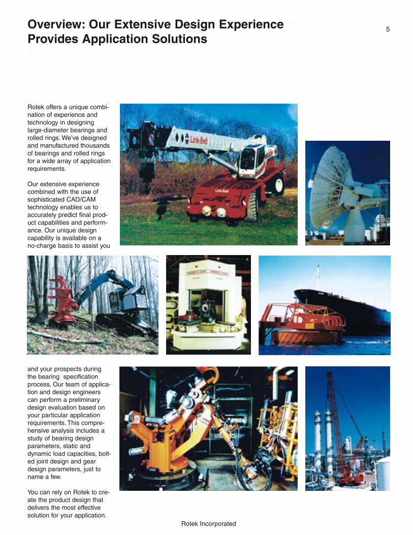
Rotek offers a unique combi-nation of experience andtechnology in designinglarge-diameter bearings androlled rings. We’ve designedand manufactured thousandsof bearings and rolled ringsfor a wide array of applicationrequirements.
Our extensive experiencecombined with the use ofsophisticated CAD/CAMtechnology enables us toaccurately predict final prod-uct capabilities and perform-ance. Our unique designcapability is available on ano-charge basis to assist you
and your prospects duringthe bearing specificationprocess. Our team of applica-tion and design engineerscan perform a preliminarydesign evaluation based onyour particular applicationrequirements. This compre-hensive analysis includes astudy of bearing designparameters, static anddynamic load capacities, bolt-ed joint design and geardesign parameters, just toname a few.
You can rely on Rotek to cre-ate the product design thatdelivers the most effectivesolution for your application.
Rotek Incorporated
Overview: Integrated Facilities ProvideComplete Manufacturing Control
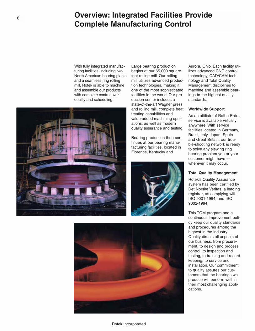
With fully integrated manufac-turing facilities, including twoNorth American bearing plantsand a seamless ring rollingmill, Rotek is able to machineand assemble our productswith complete control overquality and scheduling.
Large bearing productionbegins at our 65,000 squarefoot rolling mill. Our rollingmill utilizes advanced produc-tion technologies, making itone of the most sophisticatedfacilities in the world. Our pro-duction center includes astate-of-the-art Wagner pressand rolling mill, complete heattreating capabilities andvalue-added machining oper-ations, as well as modernquality assurance and testing.
Bearing production then con-tinues at our bearing manu-facturing facilities, located inFlorence, Kentucky and
Aurora, Ohio. Each facility uti-lizes advanced CNC controltechnology, CAD/CAM tech-nology and Total QualityManagement disciplines tomachine and assemble bear-ings to the highest qualitystandards.
Worldwide Support
As an affiliate of Rothe-Erde,service is available virtuallyanywhere. With servicefacilities located in Germany,Brazil, Italy, Japan, Spainand Great Britain, our trou-ble-shooting network is readyto solve any slewing ringbearing problem you or yourcustomer might have —wherever it may occur.
Total Quality Management
Rotek’s Quality Assurancesystem has been certified byDet Norske Veritas, a leadingregistrar, as complying withISO 9001-1994, and ISO9002-1994.
This TQM program and acontinuous improvement poli-cy keep our quality standardsand procedures among thehighest in the industry.Quality directs all aspects ofour business, from procure-ment, to design and processcontrol, to inspection andtesting, to training and recordkeeping, to service andinstallation. Our commitmentto quality assures our cus-tomers that the bearings weproduce will perform well intheir most challenging appli-cations.
6

7
Rotek Incorporated
Overview: Rotek Expertise Is AvailableAfter The Sale
Rotek offers a variety ofafter-the-sale services thatcan assist your staff in a vari-ety of ways and can extendthe service life of your bear-ing. Services include:
Installation/Change-OutConsultation and Supervision
Proper bearing installation isvital. That is why we offerconsultation services and on-site supervision for the instal-lation or change-out of anynew or replacement bearing.We can also advise you onthe proper mounting struc-ture to assure maximumbearing performance.
Preventative MaintenancePrograms
Rotek offers a contractedpreventative maintenanceprogram that provides regularinspection of your in-servicebearing and the performanceof scheduled maintenanceprocedures that can keepyour bearing in peak condi-tion and extend its servicelife.
In-Use Bearing Analysis
To further extend the servicelife of your bearings, we canperform an on-site analysisof their performance in theircurrent application. This in-
use evaluation includes non-destructive testing and com-ponent wear analysis, as wellas further maintenance rec-ommendations.
Service Life Analysis
After your bearings havebeen removed from service,we can analyze wear patterns and make recom-mendations that can providelonger service life. Bettervalue from replacement bearings may be suggested.

Rotek Incorporated
Product Line Summary
Series 1000Single Row Ball Bearing
Series 1000 bearings are constructedwith chrome-alloy steel balls with nospacers and steel rings with unhard-ened raceways. These bearings providea cost-effective solution for applicationsrequiring low-speed, bi-directional rota-tion of light loads.
Specifications
RACEWAY DIAMETERS: 12” to 42”
CAPACITIES:THRUST: 1650 to 35,200 poundsMOMENT: Not recommended for moment
loadsRADIAL: Contact Rotek
GEARING:Furnished in gearless models only
APPLICATIONS:Fifth wheels for trailers and farm vehicles
See page 40 for more information.
8
Series 3000Single Row Ball Bearing
Series 3000 bearings are an evolutionof the classic four-point contact bearingdesign, featuring offset induction-hard-ened raceway construction, the highestdegree of raceway wrap, and durableball separators. Within the limits of theircapacities, they offer an optimum com-bination of economy, reliability anddurability.
Specifications
RACEWAY DIAMETERS:Standard models from 12” to 180”Special order bearings up to 360”
CAPACITIES:THRUST: to 6,500,000 poundsMOMENT: to 21,000,000 foot-poundsRADIAL: to 1,200,000 poundsContact Rotek for load information on special order models.
GEARING:Gearless, internal or external gearing
APPLICATIONS:Stationary and mobile cranesExcavatorsStackers/reclaimersLift truck rotatorsIndustrial turntablesCapstansTurnstilesAerial liftsMining equipmentForestry equipment
See page 50 for more information.
Series 2100Single Row Ball Bearing
Series 2100 bearings are four-point con-tact bearings with induction-hardened,offset raceways. Balls are chrome-alloysteel and separated by spacers to pre-vent ball-to-ball sliding friction. Series2100 bearings are general purposebearings for medium to heavy-dutyapplications.
Specifications
RACEWAY DIAMETERS: 13” to 57”
CAPACITIES:THRUST: 7,000 to 1,100,000 poundsMOMENT: 1,400 to 390,000 foot-poundsRADIAL: 400 to 150,000 pounds
GEARING:Gearless, internal or external gearing
APPLICATIONS:Small cranes and excavatorsIndustrial turntablesCapstansTurnstilesMining equipment
See page 42 for more information.
9
Rotek Incorporated
Product Line Summary
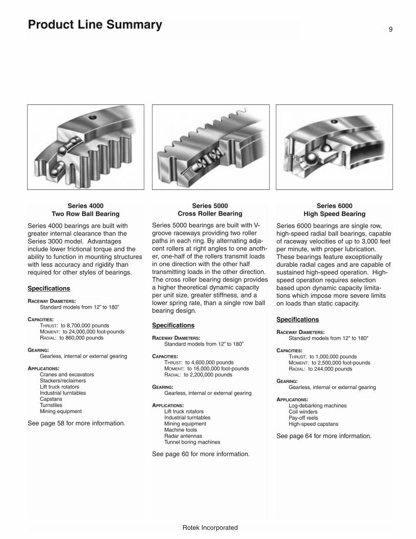
Series 4000Two Row Ball Bearing
Series 4000 bearings are built withgreater internal clearance than theSeries 3000 model. Advantagesinclude lower frictional torque and theability to function in mounting structureswith less accuracy and rigidity thanrequired for other styles of bearings.
Specifications
RACEWAY DIAMETERS:Standard models from 12” to 180”
CAPACITIES:THRUST: to 8,700,000 poundsMOMENT: to 24,000,000 foot-poundsRADIAL: to 860,000 pounds
GEARING:Gearless, internal or external gearing
APPLICATIONS:Cranes and excavatorsStackers/reclaimersLift truck rotatorsIndustrial turntablesCapstansTurnstilesMining equipment
See page 58 for more information.
Series 6000High Speed Bearing
Series 6000 bearings are single row,high-speed radial ball bearings, capableof raceway velocities of up to 3,000 feetper minute, with proper lubrication.These bearings feature exceptionallydurable radial cages and are capable ofsustained high-speed operation. High-speed operation requires selectionbased upon dynamic capacity limita-tions which impose more severe limitson loads than static capacity.
Specifications
RACEWAY DIAMETERS:Standard models from 12" to 180"
CAPACITIES:THRUST: to 1,000,000 poundsMOMENT: to 2,500,000 foot-poundsRADIAL: to 244,000 pounds
GEARING:Gearless, internal or external gearing
APPLICATIONS:Log-debarking machinesCoil windersPay-off reelsHigh-speed capstans
See page 64 for more information.
Series 5000Cross Roller Bearing
Series 5000 bearings are built with V-groove raceways providing two rollerpaths in each ring. By alternating adja-cent rollers at right angles to one anoth-er, one-half of the rollers transmit loadsin one direction with the other halftransmitting loads in the other direction.The cross roller bearing design providesa higher theoretical dynamic capacityper unit size, greater stiffness, and alower spring rate, than a single row ballbearing design.
Specifications
RACEWAY DIAMETERS:Standard models from 12” to 180”
CAPACITIES:THRUST: to 4,600,000 poundsMOMENT: to 16,000,000 foot-poundsRADIAL: to 2,200,000 pounds
GEARING:Gearless, internal or external gearing
APPLICATIONS:Lift truck rotatorsIndustrial turntablesMining equipmentMachine toolsRadar antennasTunnel boring machines
See page 60 for more information.

Rotek Incorporated
Product Line Summary10
Series 7100Vertical Thrust Bearing
Series 7100 bearings are single rowball bearings built for applications wherethe center of force remains within thebearing diameter under normal operat-ing conditions. Thrust is transmitted ata 90° contact angle, thus making themost efficient use of the bearing capaci-ty. Lift-off protection is provided to holdthe assembly together under occasionaluplifting loads.
Specifications
RACEWAY DIAMETERS:Standard models from 12” to 180”
CAPACITIES:THRUST: to 1,290,000 poundsMOMENT: Not applicable for moment loadsRADIAL: Contact Rotek
GEARING:Gearless, internal or external gearing
APPLICATIONS:Large turntablesSewage and water treatmentClarifiers, thickeners and rotary distributors
See page 66 for more information.
Series 8000Vertical Thrust Bearing
Series 8000 bearings are single rowball bearings built for applications wherethe center of force remains within thebearing diameter under normal operat-ing conditions. They offer the lowestcost per unit diameter for heavy purethrust loads. No mounting holes orgearing is provided. Rings, raceways,ball and separators only.
Specifications
RACEWAY DIAMETERS:Standard models from 12” to 180”
CAPACITIES:THRUST: from 60,000 pounds and upMOMENT: Not applicable for moment loadsRADIAL: Contact Rotek
GEARING:Available in gearless models only
APPLICATIONS:Large turntablesSewage and water treatmentClarifiers, thickeners and rotary distributors
See page 66 for more information.
Series 10,000Three Row Roller Bearing
Series 10,000 bearings are built withthree independent rows of rollers. Sinceall loadings are transmitted directly toraceway surfaces which are perpendi-cular to the load direction, the capacityof each rolling element and each race-way surface is utilized in the most effi-cient manner. The three row roller bear-ing offers more capacity per unit sizethan any other Rotek design and isinherently the stiffest style of construc-tion. Frictional torque is lower than otherstyles of Rotek bearings under mostload conditions.
Specifications
RACEWAY DIAMETERS:Standard models from 12” to 180”Special order bearings up to 360”
CAPACITIES:THRUST: to 23,000,000 poundsMOMENT: to 61,000,000 foot-poundsRADIAL: to 2,500,000 poundsContact Rotek for load information on special order models.
GEARING:Gearless, internal or external gearing
APPLICATIONS:Off-shore cranesMooring buoysStacker/ReclaimersDockside cranesShipboard cranesLadle turretsCrawler cranesExcavatorsTunnel boring machinesRadar antennas
See page 68 for more information.

11
Rotek Incorporated
Product Line Summary
Precision Bearings
Rotek offers precision bearings in singlerow ball, cross roller and three rowroller configurations. Depending onraceway diameter and bearing configu-ration, critical feature size and fit specifi-cations can be held to the followingranges:
• Runout tolerances to within .0003”• Concentricities to within .0003”• Surface flatness to within .0003”• Parallelism to within .0003”• Bolt hole positions to .010”
diameter• Gear precision equal to or
exceeding AGMA 10
Specifications
RACEWAY DIAMETERS: 12” to 180”Contact Rotek about larger sizes
CAPACITIES:Contact Rotek Application Engineering for information
GEARING:Gearless, internal or external gearing
APPLICATIONS:Precision turntables and index tablesRoboticsMedical diagnostic equipmentFilling equipmentRadar and radio telescope antennasTest stands and testing equipment
See page 76 for more information.
Series 15,000Wire-RaceTM Bearing
Rotek Wire-Race bearings are availablein single row ball, two row roller andthree row roller configurations. Thesebearings feature a replaceable, hard-ened, inserted wire raceway that allowssupporting rings to be constructed in avariety of materials, including aluminumalloys and bronze. These bearings areideal in applications where removal andreplacement of the bearing would bedifficult, where weight of the bearing isa critical consideration, and whereambient environment is corrosive tosteel bearing materials.
Specifications
RACEWAY DIAMETERS: 12” to 600”
CAPACITIES:THRUST: to 18,000,000 poundsMOMENT: to 700,000,000 foot-poundsRADIAL: to 2,000,000 pounds
GEARING:Gearless, internal or external gearing
APPLICATIONS:Radar antennasMedical equipmentAny application where weight or corrosion is a concern, or where bearing replacement would be difficult
See page 72 for more information.
Series 12,000Roller/Ball Combination Bearing
Series 12,000 bearing incorporate arow of balls and a row of rollers into thesame bearing. This combination ofrolling elements is designed to handlesmall eccentricities at relatively highaxial loads.
Specifications
RACEWAY DIAMETERS:Standard models from 12” to 250”Special order bearings up to 360”
CAPACITIES:THRUST: up to 17,500,000 poundsMOMENT: up to 51,600,000 foot-poundsRADIAL: up to 775,000 pounds
GEARING:Gearless, internal or external gearing
Series 11,000Single Row Ball Bearing
Series 11,000 bearings are constructedwith aluminum rings and plastic ballbearings to provide an economicalbearing for light load applications requir-ing a low-friction, lightweight, corrosion-resistant bearing.
Specifications
RACEWAY DIAMETERS:Standard models from 12” to 60”
CAPACITIES:THRUST: up to 4,000 poundsMOMENT: Contact RotekRADIAL: Contact Rotek
GEARING:Gearless, internal or external gearing� Series 12,000 and Series 11,000 bearings are non-cataloged products.
Contact Rotek at 800/221-8043 for more information.

13 Engineering Section Introduction
13 Load Transmission Characteristics
14 Bearing Loads Defined
14 Determining Bearing Loads
15 Sample Loading Types
16 Bearing Types
17 Raceway Hardening
18 Raceway Capacity
19 Application Service Factors
20 Bolt Capacity
21 Bolting Assumptions
22 Bolt Preload Information
23 Additional Bolting Information
24 Turning Torque Calculations
25 Gear Capacity
26 Gearing
28 Pinion Tip Relief
29 Companion Structures
30 Permissible Out-of-Flatness and Deflection in Companion Structures
31 Radial Bearing Deflections
32 Wear Measurement
34 Set-up Information
35 Lubrication and Maintenance
36 Operating Conditions and Special Requirements
37 Bearing Design Worksheet Instructions
38 Bearing Design Worksheet
12 Table of ContentsEngineering Section
Rotek Incorporated

13
Rotek Incorporated
Engineering Section
Engineering Section Introduction
This section of the catalog provides engineer-ing information to assist you in the selectionand specification of large-diameter bearings.A bearing design worksheet, beginning onpage 37, is included to allow us to assist youin the process.
We encourage you to contact our ApplicationEngineering Department at the outset of yourdesign program. Our expertise in bearingdesign and use of CAD technology can beused to accurately predict final product capa-bilities and performance.
Our expertise is available to you on a no-charge basis. We will provide a preliminarydesign evaluation based on your specificapplication requirements. This comprehensivewritten analysis generally includes a review ofbearing design parameters, static anddynamic load capacities, bolt requirementsand suggested gear specifications, just toname a few.
� To start the design process, or for more information on any aspect of Rotek’s capabili-ties, contact your local Rotek sales represen-tative or the Rotek Application EngineeringDepartment at 330/562-4000 or toll-free at800/221-8043.
Load Transmission Characteristics
A Rotek bearing is a complete, ready-to-usepackage. It is an engineered system of ballsor rollers, spacers or cages, raceways,mounting provisions, and integral gearing. Itneeds simply to be bolted in place to beoperational.
Many Rotek large-diameter bearing modelsare designed to transmit all combinations ofaxial, radial and tilting moment loads. Thiscombination load capacity is achieved in oneassembly, eliminating the weight, space andcost penalties of other rotational designs.
It is recommended that Rotek bearings bemounted to a suitable supporting companionstructure. It is essential that the companionstructure be built to appropriate specificationsto minimize bearing distortion and extendservice life. See page 29 for details.
A Rotek bearing may be utilized in applica-tions where loads will be suspended from thebearing, but special considerations regardingthe type and number of fastening bolts arerequired for these types of applications.
� We require that Rotek be consulted for assistance in the specification of bearings forsuspended load applications.
Engineering Section14
Bearing Loads Defined
Bearing loads are defined in terms ofone or a combination of axial, radial andmoment loads.
An axial load is a load that acts parallelwith the axis of rotation. Figure 1 showsa compressive axial load application. Acompressive axial load will squeezemounting surfaces together while a ten-sile axial load acts to pull the bearingaway from the supporting structure. Acompressive axial load is commonlyreferred to as a thrust load. A tensileaxial load may be referred to as either atension load or a hanging load. Tensionloads are not possible without mountingfasteners. Applications involving tensileaxial loads are subject to special designcriteria. Rotek should be consulted forsuch cases.
A radial load is a load that acts perpen-dicular to the axis of rotation. A radialload is often referred to as a side orshear load. Figure 3 shows a radialload application. In the bolted connec-tion, radial loads are resisted by the fric-tional holding power of the clampedinterface. Precision cylindrical pilots ordowels are sometimes incorporated totransmit high radial loads.
A moment load, or “overturning”moment load, acts about a line perpen-dicular to the axis of rotation. Amoment load induces thrust on one halfof the bearing and tension on the otherhalf. Moment loads result from an axialload applied at a distance from the axisof rotation (Figure 2), a radial loadapplied at a perpendicular distance fromthe plane of the bearing (Figure 4), or acombination of both axial and radialeffects (Figure 5).
A single bearing load condition consistsof all axial, radial, and moment loadcomponents which occur simultaneous-ly. Most loading situations can be ade-quately defined in two dimensions (suchas in Figures 1 through 6). Others
may require three dimensions to properly consider the loads.
It is important that only axial, radial andmoment load components which actsimultaneously are defined within abearing load case. While a consolida-tion of “worst case” loading componentsinto a single load case may be thoughtof as a conservative way to simplify abearing selection, it can have theadverse effect of an inadequate bearingselection!
Determining Bearing Loads
Bearing loads may be easily determinedusing a classical engineering approachof creating Free-Body Diagrams andthen solving for the unknown variablesusing equations of static equilibrium.
A Free-Body Diagram is a sketch show-ing forces, their vectorial direction interms of X & Y Cartesian coordinate val-ues, and X & Y perpendicular distancesof these forces relative to the center ofthe bearing.
The bearing plane becomes a cut linefor the Free-Body Diagram dividingforces left and right (Figure 4) or topand bottom (Figure 2) relative to thebearing plane. Bearing loads are simplythe reaction forces at the cut plane.
Equations of static equilibrium are usedto solve for the reactionary forces at thecut plane. These equations are:
Σ Axial Forces = 0Σ Radial Forces = 0Σ Moments = 0
The Σ symbol indicates that all loadsare added, or summed, together. Thedirections of force and moment rotationare very important in these equationsand indicates whether a value is takenas positive or negative. Moment loadsare calculated about the center of thebearing (where the center plane androtation axis of the bearing cross).
Figures 1 through 6 are examples ofFree-Body Diagrams simplified to showthe final results of solving the equilibri-um equations.
Additional methods and examples ofusing Free-Body Diagrams and equa-tions of static equilibrium to solve forreaction forces can be found in manyengineering texts and handbooks.
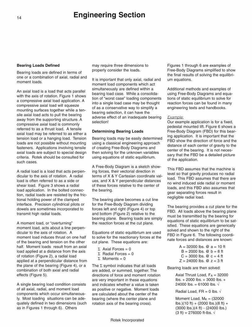
Example:Our example application is for a fixed,pedestal mounted lift. Figure 6 shows aFree-Body Diagram (FBD) for this bear-ing application. It is important that theFBD show the direction of force and thedistance of each center of gravity to thecenter of the bearing. It is not neces-sary that the FBD be a detailed pictureof the application.
This FBD assumes that the machine islevel so that gravity produces no radialload. This FBD assumes that there areno wind induced side radial or momentloads, and this FBD also assumes thatgear separating forces result in negligible radial load.
The bearing provides a cut plane for theFBD. All loads above the bearing planemust be transmitted by the bearing forequations of static equilibrium to be sat-isfied. These equations are genericallysolved and shown to the right of theFBD in Figure 6. The following coordi-nate forces and distances are known:
A = 32000 lbs. @ a = 10 ftB = 2000 lbs. @ b = 8 ftC = 3000 lbs. @ c = 4 ft
Z = 24000 lbs. @ z = 3 ft
Bearing loads are then solved:
Axial Thrust Load, FA = 32000lbs. + 2000 lbs. + 3000 lbs. +24000 lbs. = 61000 lbs. √
Radial Load, FR = 0 lbs. √
Moment Load, MK = (32000lbs.)(10 ft) + (2000 lbs.)(8 ft) +(3000 lbs.)(4 ft) - (24000 lbs.)(3 ft) = 276000 ft-lbs. √
Rotek Incorporated
15
Rotek Incorporated
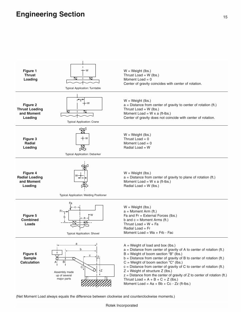
Figure 1 W = Weight (lbs.)Thrust Thrust Load = W (lbs.)Loading Moment Load = 0
Center of gravity coincides with center of rotation.
W = Weight (lbs.)Figure 2 a = Distance from center of gravity to center of rotation (ft.)
Thrust Loading Thrust Load = W (lbs.)and Moment Moment Load = W x a (ft-lbs.)
Loading Center of gravity does not coincide with center of rotation.
W = Weight (lbs.)Figure 3 Thrust Load = 0Radial Moment Load = 0
Loading Radial Load = W
Figure 4 W = Weight (lbs.)Radial Loading a = Distance from center of gravity to plane of rotation (ft.)
and Moment Moment Load = W x a (ft-lbs.)Loading Radial Load = W (lbs.)
W = Weight (lbs.)a = Moment Arm (ft.)
Figure 5 Fa and Fr = External Forces (lbs.)Combined b and c = Moment Arms (ft.)
Loads Thrust Load = W + FaRadial Load = FrMoment Load = Wa + Frb - Fac
A = Weight of load and box (lbs.)a = Distance from center of gravity of A to center of rotation (ft.)
Figure 6 B = Weight of boom section "B" (lbs.)Sample b = Distance from center of gravity of B to center of rotation (ft.)
Calculation C = Weight of boom section "C" (lbs.)c = Distance from center of gravity of C to center of rotation (ft.)Z = Weight of structure Z (lbs.)z = Distance from the center of gravity of Z to center of rotation (ft.)Thrust Load = A + B + C + Z (lbs.)Moment Load = Aa + Bb + Cc - Zz (ft-lbs.)
(Net Moment Load always equals the difference between clockwise and counterclockwise moments.)
Typical Application: Turntable
Typical Application: Crane
Typical Application: Debarker
Typical Application: Welding Positioner
Typical Application: Shovel
Assembly made up of several major parts
Engineering Section

Rotek Incorporated
Engineering Section16
Bearing Types
After loads have been calculated, referto the Product Line Summary on pages8 through 11. This summary presentsbasic data for choosing one or morestyles of bearings for your application.
Series 1000 bearings were developedfor use as “fifth-wheel” bogie steeringpivots on trailer applications. With cer-tain constraints, some Series 1000bearings have also been applied toturntable applications.
Series 2100 bearings are the most pop-ular choice for general turntable applica-tions. Their moment capacity providesstability to turntables having diameterswell in excess of the bearing diameter.They also serve the need of other appli-cations requiring combination-load bear-ing capabilities. Series 2100 bearingsare characteristically larger in diameterthan Series 3000 bearings of samecapacity. If a large diameter is desir-able, Series 2100 bearings are usuallythe economical choice within their cata-log size and capacity ranges.
Series 3000 bearings are the most pop-ular of all Rotek bearings built and areoffered in the broadest variety. In amajority of applications, they offer anoptimum combination of capacity, dura-bility and economy. A variety of bearingsare in regular production and are avail-able for prompt delivery. Custom mod-els to satisfy exact design requirementsare routine.
Series 4000 bearings are favored forapplications where minimum friction isrequired. They have somewhat greaterinternal clearance than comparableSeries 3000, 5000 and 10000 models.
Mounting structure requirements are notas critical. Cost is typically more thanSeries 2100, 3000 and 5000 types ofcomparable capacity.
Series 5000 bearings are ideally suitedto applications where extreme stiffnessis required. They are typically used inmachine tools, radar antennas and opti-cal equipment. A flat and rigid mountingstructure is essential for optimum per-formance.
Series 10000 bearings offer the highestcapacity per unit size of any Rotek bear-ing. They are used principally for higherloads, although smaller models overlapSeries 3000, 4000 and 5000 capacities.As with Series 5000 roller bearings, aflat and rigid mounting structure is criti-cal for the proper transmission of bear-ing loads. Generally, Series 10000models are substantially more costlythan Series 3000 and 5000 models forcapacity ratings under 2 million foot-pounds.
Series 6000 bearings are populardesigns for high-speed applications.Consult Rotek for specific recommenda-tions and bearing selection.
Series 7100 bearings have high contactangles and increased internal clearancemaking them an ideal selection forthrust applications where the center offorce remains within the raceway diame-ter. Lift-off protection allows the bearingto ship and mount as a self-containedpackage. Gearing is available. Frictionis low.
Series 8000 bearings are used for thrustapplications and can be less costly thanequivalent 7100 series models. They do
not provide integral gearing nor lift-offprotection. If neither feature is required,Series 8000 models provide an eco-nomical thrust bearing choice.
Note: Series 7100 and 8000 bearingsare not regularly produced in substantialquantities, so a high-production Series3000 model may prove to be more eco-nomical for small quantity applications.
With the exception of Series 1000 bear-ings, most of the previously mentionedbearings series are also available asprecision bearings with very precise tol-erances. Production of very tight toler-ances involves substantial added cost,producing price levels as much as twoto three times those of standard heavy-duty bearings. Contact Rotek forspecifics.
Rotek Series 15000 Wire-Race bearings are famous for their lightweight and high reliability. They havebeen used throughout the world in medical scanning equipment and radar antennas. They may be appropriatewhere light weight, replaceable raceways or bearing material selectionis an important consideration. Rotekdoes not recommend any attempt atself-selection. Rather, we recommendthat you call us for assistance early inyour design process.
Rotek also markets several lines ofhighly specialized bearings. Call foradditional information and assistance onSeries 11000 plastic ball bearings,Series 12000 combination ball/rollerbearings, high-temperature bearings forapplications up to 375°F and our line ofhigh-speed “Whisper” bearings.
17
Rotek Incorporated
Engineering Section
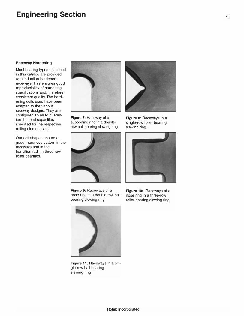
Figure 8: Raceways in a single-row roller bearingslewing ring.
Figure 10: Raceways of anose ring in a three-rowroller bearing slewing ring
Raceway Hardening
Most bearing types describedin this catalog are providedwith induction-hardened raceways. This ensures goodreproducibility of hardeningspecifications and, therefore,consistent quality. The hard-ening coils used have beenadapted to the various raceway designs. They areconfigured so as to guaran-tee the load capacities specified for the respectiverolling element sizes.
Our coil shapes ensure agood hardness pattern in theraceways and in the transition radii in three-rowroller bearings.
Figure 7: Raceway of a supporting ring in a double-row ball bearing slewing ring.
Figure 9: Raceways of anose ring in a double row ballbearing slewing ring
Figure 11: Raceways in a sin-gle-row ball bearing slewing ring
18
Rotek Incorporated
Engineering Section
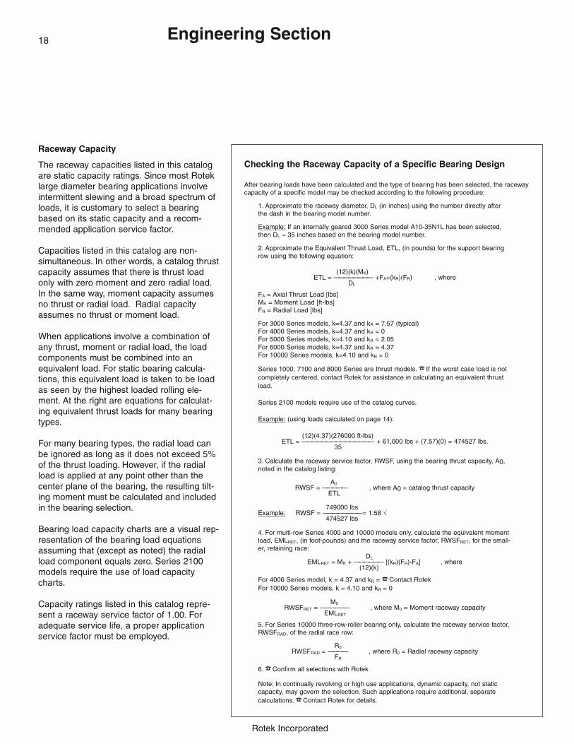
Raceway Capacity
The raceway capacities listed in this catalogare static capacity ratings. Since most Roteklarge diameter bearing applications involveintermittent slewing and a broad spectrum ofloads, it is customary to select a bearingbased on its static capacity and a recom-mended application service factor.
Capacities listed in this catalog are non-simultaneous. In other words, a catalog thrustcapacity assumes that there is thrust loadonly with zero moment and zero radial load.In the same way, moment capacity assumesno thrust or radial load. Radial capacityassumes no thrust or moment load.
When applications involve a combination ofany thrust, moment or radial load, the loadcomponents must be combined into anequivalent load. For static bearing calcula-tions, this equivalent load is taken to be loadas seen by the highest loaded rolling ele-ment. At the right are equations for calculat-ing equivalent thrust loads for many bearingtypes.
For many bearing types, the radial load canbe ignored as long as it does not exceed 5%of the thrust loading. However, if the radialload is applied at any point other than thecenter plane of the bearing, the resulting tilt-ing moment must be calculated and includedin the bearing selection.
Bearing load capacity charts are a visual rep-resentation of the bearing load equationsassuming that (except as noted) the radialload component equals zero. Series 2100models require the use of load capacitycharts.
Capacity ratings listed in this catalog repre-sent a raceway service factor of 1.00. Foradequate service life, a proper applicationservice factor must be employed.
Checking the Raceway Capacity of a Specific Bearing Design
After bearing loads have been calculated and the type of bearing has been selected, the racewaycapacity of a specific model may be checked according to the following procedure:
1. Approximate the raceway diameter, DL (in inches) using the number directly afterthe dash in the bearing model number.
Example: If an internally geared 3000 Series model A10-35N1L has been selected,then DL ≈ 35 inches based on the bearing model number.
2. Approximate the Equivalent Thrust Load, ETL, (in pounds) for the support bearingrow using the following equation:
(12)(k)(MK)ETL = ———————— +FA+(kR)(FR) , where
DL
FA = Axial Thrust Load [lbs]MK = Moment Load [ft-lbs]FR = Radial Load [lbs]
For 3000 Series models, k=4.37 and kR = 7.57 (typical)For 4000 Series models, k=4.37 and kR = 0For 5000 Series models, k=4.10 and kR = 2.05For 6000 Series models, k=4.37 and kR = 4.37For 10000 Series models, k=4.10 and kR = 0
Series 1000, 7100 and 8000 Series are thrust models. � If the worst case load is not completely centered, contact Rotek for assistance in calculating an equivalent thrustload.
Series 2100 models require use of the catalog curves.
Example: (using loads calculated on page 14):
(12)(4.37)(276000 ft-lbs)ETL = ——————————————— + 61,000 lbs + (7.57)(0) = 474527 lbs.
35
3. Calculate the raceway service factor, RWSF, using the bearing thrust capacity, A0,noted in the catalog listing:
A0RWSF = ————— , where A0 = catalog thrust capacity
ETL
749000 lbsExample: RWSF = ————————= 1.58 √
474527 lbs
4. For multi-row Series 4000 and 10000 models only, calculate the equivalent momentload, EMLRET, (in foot-pounds) and the raceway service factor, RWSFRET, for the small-er, retaining race:
DLEMLRET = MK + —————— [(kR)(FR)-FA] , where
(12)(k)
For 4000 Series model, k = 4.37 and kR = � Contact RotekFor 10000 Series models, k = 4.10 and kR = 0
M0RWSFRET = —————— , where M0 = Moment raceway capacity
EMLRET
5. For Series 10000 three-row-roller bearing only, calculate the raceway service factor,RWSFRAD, of the radial race row:
R0RWSFRAD = ———— , where R0 = Radial raceway capacity
FR
6. � Confirm all selections with Rotek
Note: In continually revolving or high use applications, dynamic capacity, not staticcapacity, may govern the selection. Such applications require additional, separate calculations. � Contact Rotek for details.
19
Rotek Incorporated
Engineering Section
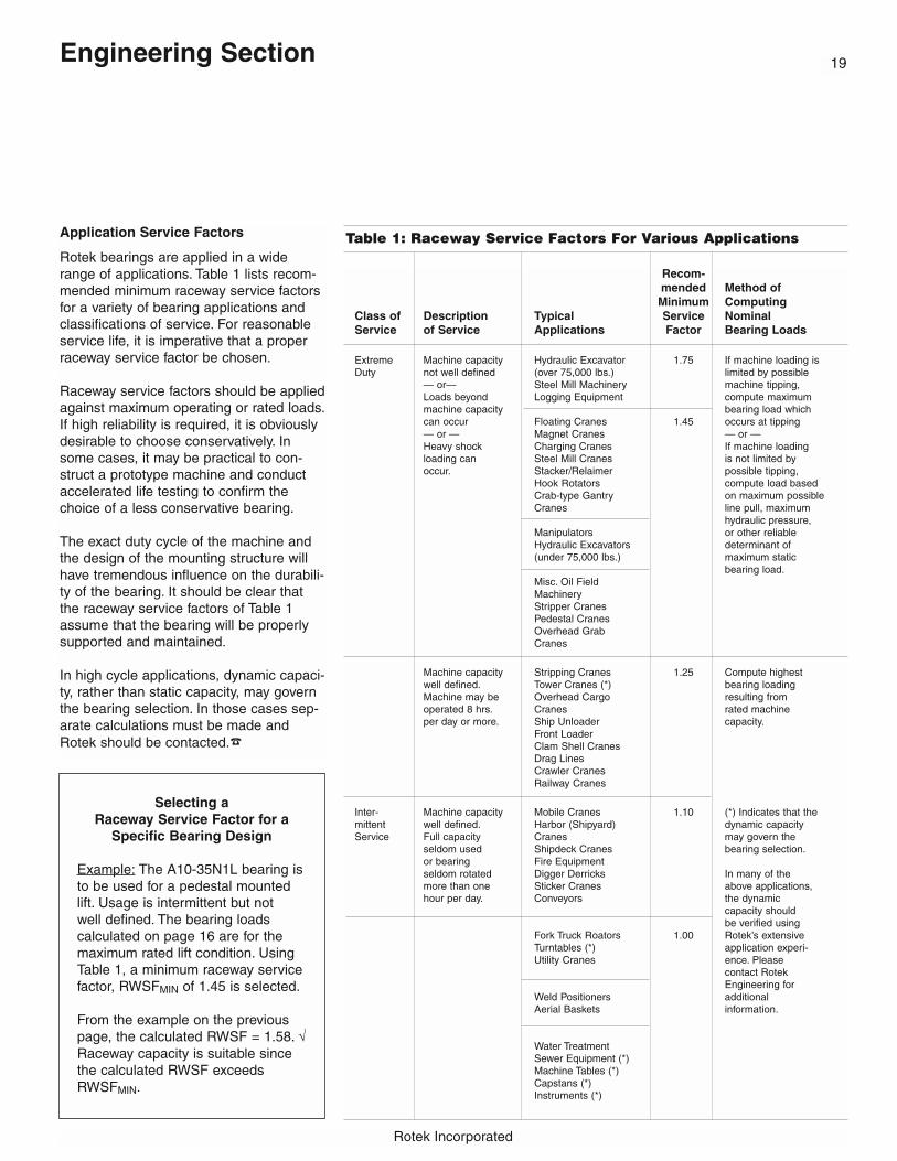
Recom-mended Method ofMinimum Computing
Class of Description Typical Service NominalService of Service Applications Factor Bearing Loads
Extreme Machine capacity Hydraulic Excavator 1.75 If machine loading is Duty not well defined (over 75,000 lbs.) limited by possible
— or— Steel Mill Machinery machine tipping,Loads beyond Logging Equipment compute maximummachine capacity bearing load whichcan occur Floating Cranes 1.45 occurs at tipping— or — Magnet Cranes — or —Heavy shock Charging Cranes If machine loadingloading can Steel Mill Cranes is not limited byoccur. Stacker/Relaimer possible tipping,
Hook Rotators compute load basedCrab-type Gantry on maximum possibleCranes line pull, maximum
hydraulic pressure,Manipulators or other reliableHydraulic Excavators determinant of (under 75,000 lbs.) maximum static
bearing load.Misc. Oil FieldMachineryStripper CranesPedestal CranesOverhead GrabCranes
Machine capacity Stripping Cranes 1.25 Compute highest well defined. Tower Cranes (*) bearing loadingMachine may be Overhead Cargo resulting fromoperated 8 hrs. Cranes rated machineper day or more. Ship Unloader capacity.
Front LoaderClam Shell CranesDrag LinesCrawler CranesRailway Cranes
Inter- Machine capacity Mobile Cranes 1.10 (*) Indicates that themittent well defined. Harbor (Shipyard) dynamic capacityService Full capacity Cranes may govern the
seldom used Shipdeck Cranes bearing selection.or bearing Fire Equipmentseldom rotated Digger Derricks In many of themore than one Sticker Cranes above applications,hour per day. Conveyors the dynamic
capacity shouldbe verified using
Fork Truck Roators 1.00 Rotek’s extensiveTurntables (*) application experi-Utility Cranes ence. Please
contact RotekEngineering for
Weld Positioners additionalAerial Baskets information.
Water TreatmentSewer Equipment (*)Machine Tables (*)Capstans (*)Instruments (*)
Table 1: Raceway Service Factors For Various ApplicationsApplication Service Factors
Rotek bearings are applied in a widerange of applications. Table 1 lists recom-mended minimum raceway service factorsfor a variety of bearing applications andclassifications of service. For reasonableservice life, it is imperative that a properraceway service factor be chosen.
Raceway service factors should be appliedagainst maximum operating or rated loads.If high reliability is required, it is obviouslydesirable to choose conservatively. Insome cases, it may be practical to con-struct a prototype machine and conductaccelerated life testing to confirm thechoice of a less conservative bearing.
The exact duty cycle of the machine andthe design of the mounting structure willhave tremendous influence on the durabili-ty of the bearing. It should be clear thatthe raceway service factors of Table 1assume that the bearing will be properlysupported and maintained.
In high cycle applications, dynamic capaci-ty, rather than static capacity, may governthe bearing selection. In those cases sep-arate calculations must be made andRotek should be contacted.�
Selecting a Raceway Service Factor for a
Specific Bearing Design
Example: The A10-35N1L bearing isto be used for a pedestal mountedlift. Usage is intermittent but not well defined. The bearing loads calculated on page 16 are for themaximum rated lift condition. UsingTable 1, a minimum raceway servicefactor, RWSFMIN of 1.45 is selected.
From the example on the previouspage, the calculated RWSF = 1.58. √Raceway capacity is suitable sincethe calculated RWSF exceedsRWSFMIN.
Rotek Incorporated
Engineering Section20
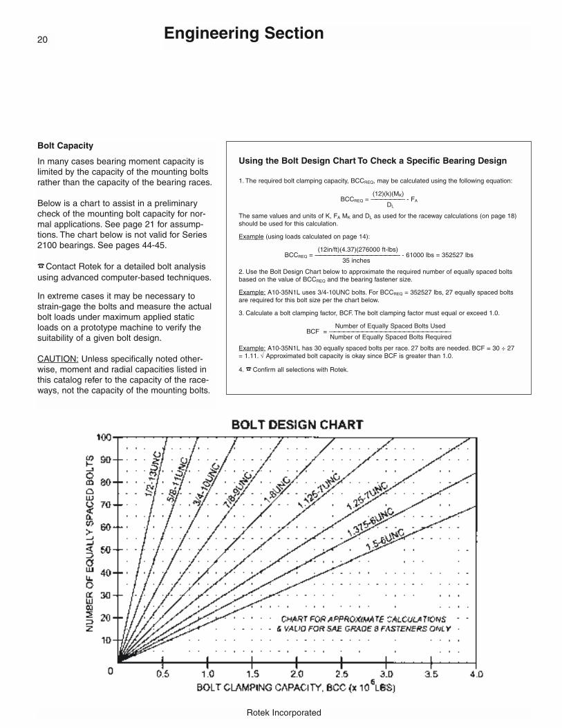
Bolt Capacity
In many cases bearing moment capacity islimited by the capacity of the mounting boltsrather than the capacity of the bearing races.
Below is a chart to assist in a preliminarycheck of the mounting bolt capacity for nor-mal applications. See page 21 for assump-tions. The chart below is not valid for Series2100 bearings. See pages 44-45.
�Contact Rotek for a detailed bolt analysis using advanced computer-based techniques.
In extreme cases it may be necessary tostrain-gage the bolts and measure the actualbolt loads under maximum applied staticloads on a prototype machine to verify thesuitability of a given bolt design.
CAUTION: Unless specifically noted other-wise, moment and radial capacities listed inthis catalog refer to the capacity of the race-ways, not the capacity of the mounting bolts.
Using the Bolt Design Chart To Check a Specific Bearing Design
1. The required bolt clamping capacity, BCCREQ, may be calculated using the following equation:
(12)(k)(MK)BCCREQ = ——————— - FA
DL
The same values and units of K, FA MK and DL as used for the raceway calculations (on page 18)should be used for this calculation.
Example (using loads calculated on page 14):
(12in/ft)(4.37)(276000 ft-lbs)BCCREQ = —————————————————— - 61000 lbs = 352527 lbs
35 inches
2. Use the Bolt Design Chart below to approximate the required number of equally spaced boltsbased on the value of BCCREQ and the bearing fastener size.
Example: A10-35N1L uses 3/4-10UNC bolts. For BCCREQ = 352527 lbs, 27 equally spaced boltsare required for this bolt size per the chart below.
3. Calculate a bolt clamping factor, BCF. The bolt clamping factor must equal or exceed 1.0.
Number of Equally Spaced Bolts UsedBCF = ——————————————————————————
Number of Equally Spaced Bolts Required
Example: A10-35N1L has 30 equally spaced bolts per race. 27 bolts are needed. BCF = 30 ÷ 27= 1.11. √ Approximated bolt capacity is okay since BCF is greater than 1.0.
4. � Confirm all selections with Rotek.

21
Rotek Incorporated
Engineering Section
Bolting Assumptions
To achieve good service life of a large-diameter bearing, all fastening boltsmust be adequately sized and carefullypreloaded. In our Research andDevelopment Department we systemati-cally test and measure bolted bearingconnections to quantify the factors thatinfluence the bolted joint.
The primary influential factors whichhave been deduced from these testresults are incorporated into computercalculation programs. These calculationsare run by the Rotek ApplicationEngineering department on a no-chargebasis to our customers. Bolt curvesgiven in this catalog are supplied forguidance only. All bolt calculationsshould be checked by RotekEngineering.
For Rotek’s bolt calculations to be valid,the following conditions must normallyapply:
a) The axial load Fa acts as compres-sion load, i.e. the axial operating forceFa resulting from the axial load does notsubject the bolts to tensile stress (com-pare Figures 12 and 13).
b) The bolts are equally spaced on thebolt hole circles.
c) The companion structures meet ourtechnical requirements (see page 29).
d) The bearing and companion struc-tures are made of steel.
e) Cast resin grouting is not used inmounting the bearing.
f) The clamping length is at least 5•d forbearings with a complete ring crosssection and at least 3•d for profiledrings, such as Series 2100 (with d beingthe bolt diameter). Smaller clampinglengths are more sensitive to loss ofpreload; such bolt connections musttherefore be checked at more frequent
intervals. Poor bearing load distributionmay also occur if small clampinglengths are used, resulting in bindingand or short raceway life.
g) There are at least six free threads inthe loaded part of the bolt.
� If the above assumptions are not the case, Rotek must be consulted
Accurate load data is imperative formeaningful bolt calculation results.Recognize that a load case critical tothe bearing selection based on racewaycapacity may not be the same as theload case critical to a selection basedon bolt capacity. All critical load casesmust be checked.
The support surface and thread axis forthe mounting fasteners must be at rightangles.
In the absence of pilots, the radial loadis transmitted proportionately at thebearing/structure interface by frictionresulting from the clamping force of thebolts.
It is very important that the selectedbearing remains clamped against itssupporting structure at all times. Sizingfasteners by this method according toRotek’s bolt calculation assumptionsresults in a reasonable safety factoragainst ultimate bolt failure. However,the absence of a bolt failure alone doesnot indicate proper clamping. Withoutproper clamping, raceway capacity iscompromised and bearing longevity isreduced.
It is assumed that fasteners will be pre-tensioned by reliable means and thatbolt tension will be checked and main-tained over the life of the bearing.Installation and maintenance instruc-tions are found on pages 34-35. Accessholes should be provided as necessaryto check and maintain bolt tightness inthe field.
Rotek’s bolt calculation method hasproven to be reliable for thousands ofbearing applications. However, there arenumerous, unique factors that exist thatcan adversely influence the bolted jointconnection which are either unknown orbeyond the scope of practical evaluationin a bearing selection. Therefore, Rotekstrongly encourages testing of the fas-tened bolts prior to releasing new equip-ment into the marketplace.
The chosen fastener type and strengthclass must be guaranteed by the suppli-er. Look for labeling to DIN, SAE or ISOstandards.
Figure 12: “Supported” axial loadBolt tension results from Mk only.
Figure 13: “Suspended” axial loadBolt tension results from Mk and the suspended load.

Rotek Incorporated
Engineering Section22
Bolt Preload Information
Table 2 gives guidance values for clamp-ing loads for bolts up to 2-1/2” and tight-ening torque for bolts up to 1-1/4”. Notightening torques are given in Table 2 forfasteners larger than 1-1/4” as our experi-ence shows that the frictional values varytoo greatly. It is better to use a hydraulicbolt tensioner for these bolts.
Fasteners should be torqued to achieve aclamp load up to 70% of the load it takesto yield a bolt under pure tension.Preloading beyond this 70% value is notrecommended if fasteners are torquedsince torsional stresses must also be con-sidered in a combined stress state.
Hydraulic bolt tensioners preload fasten-ers by pure axial forces only. Fastenerspreloaded by means not inducing torsion-al stresses may be preloaded to a clampload up to 90% of the bolt’s yield point.
When specifying a bolt preload value,either in terms of clamp load or mountingtorque, take into account the accuracy ofthe tightening method and the tighteningdevice to maximize pretensioning withoutexceeding the design clamp load. Thenominal reference mounting torque valuesin Table 2 allow for a variation of ±10%.
Tightening torque will depend on severalfactors, especially the friction value in thethread and at the bolt head or nut contactsurface. Torque values given in Table 2assume a mean coefficient of friction of0.14 at these interfaces. Due to the manyinfluencing factors, torque values are presented for reference only. We stronglyurge that sample tests be made to establish specific torque values.
Reference pages 34-35 for mounting fastener installation and maintenanceinstructions.
ASTM A-490/Grade 8 (130,000 psi yield)
Bolt Tensile Clamp Load Clamp Load Torque Ref. Nominal Ref.Size Area at 90% Yield at 70% Yield at 70% Yield Mtg. Torque
(sq. in.) (lbs.) (lbs.) (ft-lbs) (ft-lbs)
1/4-20 UNC 0.0318 2,894 11 10
5/16-18 UNC 0.0524 4,768 24 22
3/8-16 UNC 0.0775 7,053 42 38
7/16-14UNC 0.1063 9,673 67 60
1/2-13 UNC 0.1419 16,602 12,913 102 92
9/16-12 UNC 0.182 21,294 16,562 147 132
5/8-11 UNC 0.226 26,442 20,566 204 184
3/4-10 UNC 0.334 39,078 30,394 361 325
7/8-9 UNC 0.462 54,054 42,042 582 524
1-8 UNC 0.606 70,902 55,146 873 786
1 1/8-7 UNC 0.763 89,271 69,433 1,237 1,113
1 1/4-7 UNC 0.969 113,373 88,179 1,745 1,571
1 3/8-6 UNC 1.155 135,135 105,105
1 1/2-6 UNC 1.405 164,385 127,855
1 3/4-5 UNC 1.90 222,300 172,900
2-4.5 UNC 2.50 292,500 227,500
2 1/4-4.5 UNC 3.25 380,250 295,750
2 1/2-4 UNC 4.00 468,000 364,000
DIN 10.9 (136,335 psi yield) fasteners
Bolt Tensile Clamp Load Clamp Load Torque Ref. Nominal Ref.Size Area at 90% Yield at 70% Yield at 70% Yield Mtg. Torque
(sq. in.) (lbs.) (lbs.) (ft-lbs) (ft-lbs)
M5 x 0.8 0.0220 2,101 6.6 5.9M6 x 1 0.0312 2,973 11.4 10.3M8 x 1.25 0.0567 5,414 27 25
M10 x 1.5 0.0899 8,580 55 50M12 x 1.75 0.1307 16,033 12,470 96 86M14 x 2 0.178 21,872 17,011 151 136M16 x 2 0.243 29,860 23,224 229 206M18 x 2.5 0.298 36,516 28,401 317 285M20 x 2.5 0.380 46,596 36,241 457 412M22 x 2.5 0.470 57,627 44,821 612 551M24 x 3 0.547 67,136 52,217 782 704M27 x 3 0.711 87,296 67,897 1,143 1,029M30 x 3.5 0.870 106,696 82,986 1,549 1,394M33 x 3.5 1.076 131,991 102,659M36 x 4 1.266 155,384 120,854M39 x 4 1.513 185,624 144,374M42 x 4.5 1.74 213,011 165,675M45 x 4.5 2.02 247,245 192,302M48 x 5 2.28 279,577 217,449M52 x 5 2.73 334,732 260,347M56 x 5.5 3.15 386,082 300,286M60 x 5.5 3.66 448,845 349,101
Table 2: Clamping Forces and Tightening Torques
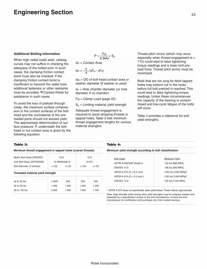
Table 3:
23
Rotek Incorporated
Engineering Section
Additional Bolting Information
When high radial loads exist, catalogcurves may not suffice in checking theadequacy of the bolted joint. In suchcases, the clamping friction contactbond must also be checked. If theclamping friction contact bond is insufficient to transmit the radial load,additional fasteners or other restraintsmust be provided. �Contact Rotek for assistance in such cases.
To avoid the loss of preload throughcreep, the maximum surface compres-sion in the contact surfaces of the bolthead and the nut/material of the pre-loaded parts should not exceed yield.The approximate determination of sur-face pressure, P, underneath the bolthead or nut contact area is given by thefollowing equation:
FMP = ———< Sy0.9•AP
AP = Contact Area
πAP = ——(d2w - d2h)
4
dW = OD of bolt head contact area orwasher diameter (if washer is used)
dh = Hole chamfer diameter (or holediameter if no chamfer)
FM = Clamp Load (page 22)
Sy = Limiting material yield strength
Adequate thread engagement isrequired to avoid stripping threads intapped holes. Table 3 lists minimumthread engagement lengths for variousmaterial strengths.
Thread pitch errors (which may occurespecially when thread engagement is >1*D) could lead to false tighteningtorque readings and a lower bolt pre-load force. Thread pitch errors must beminimized.
Bolts that are too long for blind tappedholes may bottom out in the holesbefore full bolt preload is reached. Thiscould lead to false tightening torquereadings. Under these circumstancesthe capacity of the bearing is compro-mised and low-cycle fatigue of the boltswill occur.
Table 4 provides a reference for boltyield strengths.
Minimum thread engagement in tapped holes (coarse threads)
Metric Bolt Class (DIN/ISO) 10.9 12.9
Inch Bolt Class (ASTM/SAE) A-490/Grade 8 A-574
Bolt Diameter, D (inches) <1.25 ≥1.25 <1.25 ≥1.25
Threaded material yield strength
up to 35 ksi 1.25•D N/A N/A N/A
35 to 50 ksi 1.0•D 1.2•D 1.2•D 1.4•D
50 to 100 ksi 0.9•D 1.0•D 1.0•D 1.1•D
Minimum yield strength according to bolt classification
Bolt Class Minimum Yield
ASTM A-490/SAE Grade 8 130 ksi [896 MPa]
DIN/ISO 10.9 136 ksi [940 MPa]
ASTM A-574 (D ≤ 0.5 inch) (150 ksi [1034 MPa])*
ASTM A-574 (D > 0.5 inch ) (145 ksi [1000 MPa])*
DIN/ISO 12.9 160 ksi [1100 MPa]
* ASTM A-574 does not specifically state yield stress. These values approximate.
Note: High-strength bolts having other yield strengths may be uniquely marked andclassified by a specification unique to the bolt manufacturer. Consult the bolt manufacturer for certification and purchase only from trusted sources.
Table 4:

Rotek Incorporated
Turning Torque Calculations
Turning torque can be substantial andmust be taken into consideration whendealing with large diameter bearings.Classical theory and empirical data hasbeen used in establishing a means toestimate bearing turning torque. Usingthe equations and values on this page,a design torque value can be derived.
Factors affecting torque include thebearing’s frictional coefficient, theapplied loads, the load distribution, themounting orientation, the rolling elementseparators, the flatness and stiffness ofthe supporting structure, the viscosityand amount of grease in the bearing,the seal type and preload, and the pres-ence of lubrication at the sealing inter-face. In addition there are other forcessuch as gravity, wind and inertia thatmust be overcome to rotate a bearing.The torque required to rotate a bearingis a function of all of these influences.
1. Freestate Torque, TF:Freestate torque, TF, is the frictionaltorque of the bearing as it arrives “out ofthe box” before any other load isapplied. Freestate torque is usuallyignored when bearing loads are high.However, under relatively light loads,freestate torque values must be takeninto account. An estimate of turningtorque for most bearings may be takenfrom the following graph:
This graph results from a statisticalstudy of Series 3000 type ball bearingswith diameters from 12 inches to 90inches, two seals, ground raceways, andinternal clearance. These curves do notinclude peak values.
Bearings without seals typically exhibitlower freestate torque. Preloaded bear-ings (bearings manufactured with nega-tive internal clearance) typically exhibitgreater freestate torque. Freestatetorque for special bearing designs mustbe evaluated on an individual basis.� If required, specially designed bearings with reduced torque can besupplied. Contact Rotek for more information.
2. Load Friction Torque, TL:The load friction torque is due to themagnitude of the bearing loads.Average running torque, TR, under idealconditions can be found according tothe following equation:
µ FA•DL k•FR•DLTR = ——(k• MK + ———— + —————)2 12 24
Starting torque, TS, is typically one-thirdgreater than the running torque:
TS ≈ 1.33 * TR
Turning torque can vary considerablyeven between supposedly identicalbearings. To account for peak loads, it isrecommended that a significant servicefactor be employed to assure that suffi-cient power will be available to rotatethe bearing even under adverse circum-stances. The suggested design load fric-tion torque, TL, is calculated as follows:
TL = fT * TR
where fT is a value from 2 to 5.
The highest value of fT should be usedwhen the supporting surfaces are at thehigh end of the flatness and stiffnesslimits (see page 30) and for designs thatwill be operated until the maximum wearallowable wear limit is reached (seepage 32).
3. Other Torque Loads, TE:In addition to frictional torque, othersources of torque must be consideredwhen sizing a drive unit. These mayinclude affects from wind loads, gravita-tional forces, drag loads, and accelera-tion inertia.
TE = Twind + Tgravity + Tdrag + Tinertia + ....
4. Bearing Torque, T:Bearing torque, T, is the summation offreestate, load friction and all otherexternal torque load components.
T = TF + TL + TE
Power Requirements, P:
n•TP = ——————[hp]
5252• η1 hp = 745.7 watts
Symbols Used [units]:DL = Bearing race diameter [inches]FA = Axial load [lbs.]
FR = Radial load [lbs.]
k = Load distribution factor. k = 4.37 for ballbearings and k = 4.1 for roller bearings.
MK = Moment load [ft-lbs.]
n = Rotational speed [rpm]
P = Power [horsepower, hp]
T = Turning torque [ft-lbs.]
η = Drive efficiency
µ = Friction coefficient
Engineering Section24
Friction Coefficient, µ, values for various bearing models:
= 0.008 for Series 2100: L4, L6
= 0.006 for Series 2100: L9
= 0.006 for Series 3000
= 0.004 for Series 4000
= 0.004 for Series 5000
= 0.004 for Series 6000
= 0.004 for Series 7100
= 0.004 for Series 8000
= 0.003 for Series 10,000

25
Rotek Incorporated
Engineering Section
Gear Capacity
Many Rotek bearings are supplied withgear teeth cut in one of the race rings.Adequate gear capacity must be verified.
The catalog listings provide tangentialtooth load capacities. The catalog valueis the rated static stall capacity for thetooth.
Intermittent shock loads should notexceed 140% of the catalog rating.
To achieve a reasonable gear life, it isrecommended that the normal maximum working load not exceed 71%of the catalog ratings. This is a generalguideline that is suitable for a widerange of Rotek applications, however,may not be suitable for all applications.
In high use or continually revolvingapplications, special dynamic calcula-tions may be in order. Such applicationsrequire additional, separate calculations.�Contact Rotek for assistance.
Tangential tooth load is related to turn-ing torque according to the followingequation:
24•TTTL = ———— , where
PD
TTL = Tangential tooth load (lbs.)T = Turning Torque (ft-lbs.)PD = Gear Pitch Diameter (inches)
The number of teeth, N, the diametralpitch, DP, and the pitch diameter arerelated as follows:
NPD = ———
DP
The above equations are valid for eitherthe ring gear or pinion.
The tangential tooth load of the pinionalways equals the tangential tooth loadof the gear:
TTLpinion = TTLgear
Verifying Gear Capacity of a Specific Bearing Design
Example: The pedestal lift using model A10-35N1L always operates indoors and on alevel surface. The internal ring gear will be driven by a single, 18 tooth pinion. The bearing is accelerated and decelerated very slowly to and from rest resulting in minimalinertia forces. A stop prevents full rotation of the bearing. At the stop, the pinion drivestalls with 30000 inch-pounds of torque.
Nominal Maximum Working Loads:
1. Starting torque is estimated with the formulas defined on page 24 of thecatalog:
µ FA•DL k•FR•DLT = TF + TL = TF + fT• ——[k•MK + ————— + ——————]
2 12 24
.006 (61000)(35) (4.37)(0)(35)T = 250 + 2•——— [(4.37)(276000) + ——————— + ————————]
2 12 24
T = 8554 ft-lbs
2. The tangential tooth load under normal maximum working loads is calcu-lated using the gear pitch diameter, PD, shown in the catalog listing. PD =31.429 inches from the catalog listing.
24•T (24)(8554)TTL = ————— = ——————— = 6532 lbs
PD 31.429
3. From the catalog listing for bearing model A10-35N1L, the tangential toothload capacity is 12100 lbs. The normal working capacity is 71% of this value.
Normal working load capacity = (.71)(12100) = 8591 lbs
6532 lbs working load< 8591 lbs normal working load capacity
√ Okay for normal loads
Gear Stall Loads:
1. The pitch diameter, PDpinion, of the pinion is calculated based on the diame-tral pitch, DP, and the number of pinion teeth, Npinion.
Npinion 18PDpinion = ————— = ——— = 5.1429”
DP 3.5
2. Pinion torque, Tpinion, at stall, = 30000 in-lbs = 2500 ft-lbs
3. The pinion tangential tooth load, TTLpinion, is determined as:
(24)(Tpinion) (24)(2500)TTLpinion = ———————— = ——————— = 11667 lbs
(DPpinion) (5.1249)
4. TTLgear = TTLpinion = 11667 lbs
5. 11667 lbs (stall load) < 12100 lbs (stall capacity)
√ Okay for stall loads
Dynamic Gear Loads:
In continually revolving or high use applications, dynamic capacity, ratherthan static capacity, may govern the gearing requirement. Such applicationsrequire additional, separate calculations. � Contact Rotek for details.
Induction Hardening Note: Certain models have gear teeth induction hard-ened for wear resistance. Induction hardened gearing can provide a substan-tial improvement in gear life against surface wear and fatigue.

Rotek Incorporated
26 Engineering Section
Gearing
Rotek large-diameter bear-ings are, in the majority ofcases, supplied with spurgearing. A gear cut into oneof the bearing rings offers theadvantage that an additionaldriving gear is not required,which helps to reduce designwork and costs.
All bearings depicted withgears are, of course, avail-able ungeared.
Special gear types, includingthose for bearings with diam-eters exceeding those shownin Rotek product catalogs,are also available uponrequest.
The permissible tangentialforces are listed in the dimen-sional tables of respectiveRotek products. The maxi-mum values shown in thesetables refer to stall load conditions.
The permissible bendingstresses at the root of thetooth for 250/300 BHNquenched and temperedmaterial is:
• 25,000 psi for normal loads
• 35,000 psi for stallloads and
• 50,000 psi for shock loads
� Higher values may be allowed for infrequentlyoccurring extreme loads, butthese applications should bereviewed and approved byRotek.
(See operating conditions and special requirements,page 36.)
For the bending stress calcu-lation it should, however, benoted that the meshing con-ditions in highly stressedgears are not comparablewith those of standard geartransmissions where bearingmounting and shafts can beregarded as relatively rigid.
In large-diameter bearings,the drive is generally mount-ed overhung. Due to the hightangential forces to be trans-mitted, the pinion shaft willbend. It is, therefore, notadvisable to employ a contactratio for preliminary designpurposes.
In the case of highly stressedgears, a tip relief may bedesirable (see page 28).
The bearings listed in the cat-alog tables are sometimesprovided with an addendumor profile modification.Rotek should be provided thepinion data in order to checkthe meshing conditions.During the installation of the
large-diameter bearing andthe drive pinion, adequatebacklash must be assured.
Three teeth can be marked ingreen at the highest point ofeccentricity. This will allowsatisfactory adjustment of thebacklash.
After final assembly of theequipment and after tighten-ing all of the fastening bolts,the backlash must bechecked using a feeler gaugeor a lead wire.
The minimum allowable back-lash is dependent upon theprecision of the bearing, therigidity of the mounting struc-ture, and the pitch of the gearteeth.
� Most models have gear teeth that are cut with suffi-cient backlash to allow forproper meshing on standardcenter distances. Call Rotekfor more information.

27
Rotek Incorporated
For gears subjected to hightooth flank stress, hardenedgears have proven very satis-factory. Depending on pitchdiameter and ring diameter,the gear rings are subjectedto spin hardening or individ-ual tooth induction-hardening,with the latter predominantlyin the form of tooth contourhardening. Both methods pro-vide improved flank load car-rying capacity. Flank harden-ing with hardness phase-outin the region of the root radii,leaving the root radiusunhardened, will reduce theload capacity at the root.
Hardened gears require anindividual calculation.Pinion/gear alignment ismore critical with surfacehardened gearing. If misalign-ment or deflection is exces-sive, tooth breakage mayoccur prematurely, making iteven more critical than toothflank wear.
Catalog models with induc-tion hardened gears arehardened according to Figure16 (tooth contour hardening).
Figure 14: Spin hardening Figure 15: Tooth flank hardening
Figure 16: Tooth contour hardening Figure 17: Backlash
Engineering Section
Rotek Incorporated
28 Engineering Section
Pinion Tip Relief
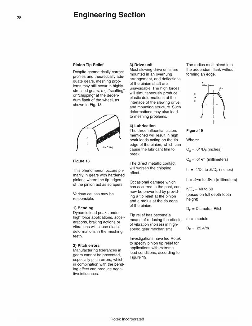
Despite geometrically correctprofiles and theoretically ade-quate gears, meshing prob-lems may still occur in highlystressed gears, e g. “scuffing”or “chipping” at the deden-dum flank of the wheel, asshown in Fig. 18.
Figure 18
This phenomenon occurs pri-marily in gears with hardenedpinions where the tip edgesof the pinion act as scrapers.
Various causes may beresponsible.
1) BendingDynamic load peaks underhigh force applications, accel-erations, braking actions orvibrations will cause elasticdeformations in the meshingteeth.
2) Pitch errorsManufacturing tolerances ingears cannot be prevented,especially pitch errors, whichin combination with the bend-ing effect can produce nega-tive influences.
3) Drive unitMost slewing drive units aremounted in an overhungarrangement, and deflectionsof the pinion shaft areunavoidable. The high forceswill simultaneously produceelastic deformations at theinterface of the slewing driveand mounting structure. Suchdeformations may also leadto meshing problems.
4) LubricationThe three influential factorsmentioned will result in highpeak loads acting on the tipedge of the pinion, which cancause the lubricant film tobreak.
The direct metallic contactwill worsen the chippingeffect.
Occasional damage whichhas occurred in the past, cannow be prevented by provid-ing a tip relief at the pinionand a radius at the tip edgeof the pinion.
Tip relief has become ameans of reducing the effectsof vibration (noises) in high-speed gear mechanisms.
Investigations have led Rotekto specify pinion tip relief forapplications with extremeload conditions, according toFigure 19.
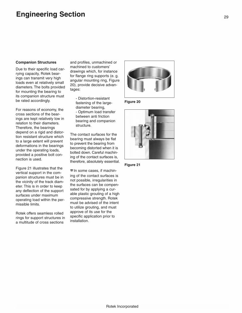
The radius must blend intothe addendum flank withoutforming an edge.
Figure 19
Where:
Ca = .01/DP (inches)
Ca = .01•m (millimeters)
h = .4/DP to .6/DP (inches)
h = .4•m to .6•m (millimeters)
h/Ca = 40 to 60(based on full depth toothheight)
DP = Diametral Pitch
m = module
DP = 25.4/m
29
Rotek Incorporated
Engineering Section
Companion Structures
Due to their specific load car-rying capacity, Rotek bear-ings can transmit very highloads even at relatively smalldiameters. The bolts providedfor mounting the bearing toits companion structure mustbe rated accordingly.
For reasons of economy, thecross sections of the bear-ings are kept relatively low inrelation to their diameters.Therefore, the bearingsdepend on a rigid and distor-tion resistant structure whichto a large extent will preventdeformations in the bearingsunder the operating loads,provided a positive bolt con-nection is used.
Figure 21 illustrates that thevertical support in the com-panion structures must be inthe vicinity of the track diam-eter. This is in order to keepany deflection of the supportsurfaces under maximumoperating load within the per-missible limits.
Rotek offers seamless rolledrings for support structures ina multitude of cross sections
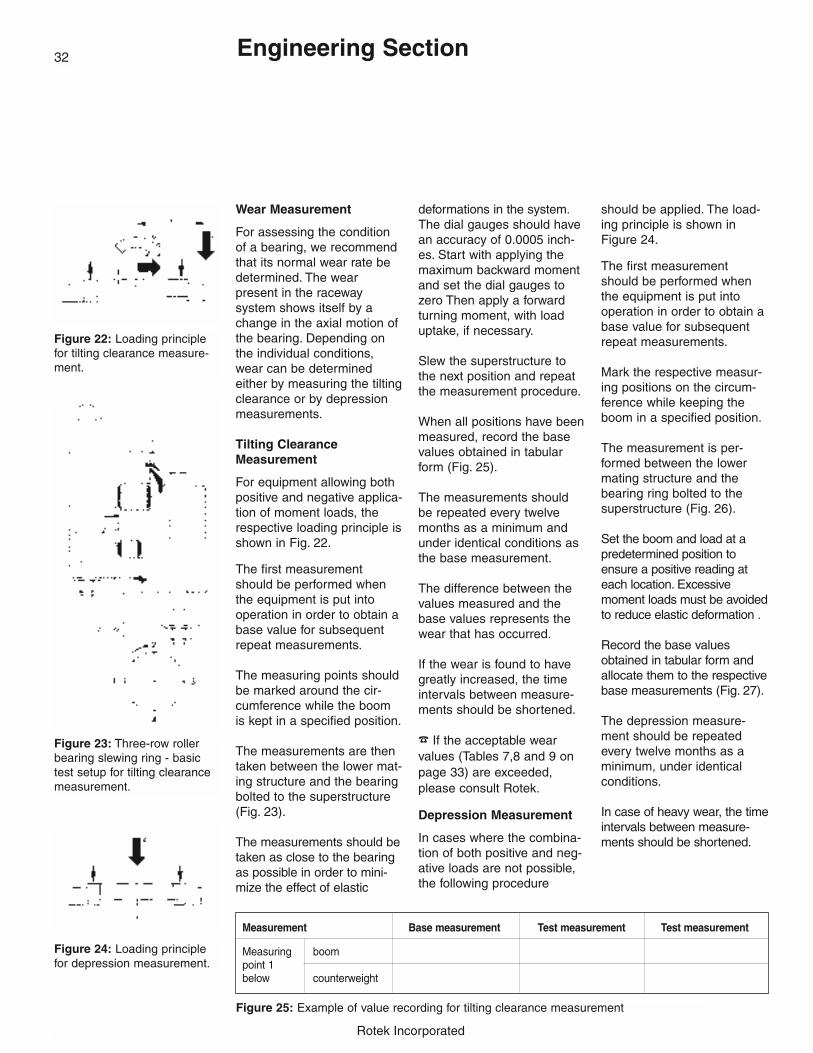
and profiles, unmachined ormachined to customers’drawings which, for instancefor flange ring supports (e. g.angular mounting ring, Figure20), provide decisive advan-tages:
- Distortion-resistant fastening of the large-diameter bearing,- Optimum load transfer between anti friction bearing and companion structure.
The contact surfaces for thebearing must always be flatto prevent the bearing frombecoming distorted when it isbolted down. Careful machin-ing of the contact surfaces is,therefore, absolutely essential.
� In some cases, if machin-ing of the contact surfaces isnot possible, irregularities inthe surfaces can be compen-sated for by applying a cur-able plastic grouting of a highcompressive strength. Rotekmust be advised of the intentto utilize grouting, and mustapprove of its use for thespecific application prior toinstallation.
Figure 20
Figure 21

Rotek Incorporated
Engineering Section
Permissible Out-of-Flatness and Deflectionin Companion Structures.
The maximum permissibleout-of-flatness, includingslope and axial deflectionsare detailed in the respective tables.
The permissible deviationslisted in Table 5 for the different design types areindicative values.
Should the values beexceeded, Rotek must beconsulted.
Regarding the slope of themachined surfaces, the figures shown in Table 5refer to a support width of 4inches.
Another important factor isto ensure that the maximum value is reachedonly once per 180˚ sector.
To avoid larger deviationsand the occurrence ofpeaks in smaller sectors,any deviations in the rangeof 0˚ - 90˚ - 180˚ must onlyrise or fall gradually.
As in the case of out-of-flat-ness, any deflections in thesupporting structure mustnot be allowed to lead tolocalized buckling whichmight cause tight sports inthe raceways. This couldeasily lead to local overloads. For this reason,the same conditions as forthe out-of-flatness apply.
For the maximum permissi-ble deflections given inTable 6, the permissibleslope may be twice thevalue given in Table 5.(Reference width 4 inches).
The maximum permissibleaxial deflections shown inTable 6 apply to all bearingtypes and are indicated asa function of the trackdiameter of the bearing.
Table 5
Out-of Flatness including slope per support surface in inch-
es
Track Double-row Single-row Roller Diameter ball bearings ball bearings bearingin inches Axial ball 4-point contact slewingDL bearings bearings* rings
to 40 0.008 0.006 0.004
to 60 0.010 0.007 0.005
to 80 0.012 0.009 0.006
to 100 0.014 0.010 0.007
to 160 0.016 0.012 0.008
to 240 0.020 0.016 0.012
The figures in Table 5 may not be used for special configurations of precision bearings which have a higher running accuracy and a smallbearing clearance. *Values may be doubled for standard Series 2100models L4 and L6. For Series 1000 mounting flatness requirements, seepage 40.
30
Table 6
Maximum permissible axial deflections for contact surfaces at a maximum operating load.
Track-diameter Maximum axialin inches deflections
DL in inches
to 40 0.024
to 60 0.031
to 80 0.040
to 100 0.051
to 120 0.063
to 140 0.080
to 160 0.100
to 180 0.118
to 200 0.142
to 220 0.165
to 240 0.189
to 280 0.228
to 310 0.275

31
Rotek Incorporated
Engineering Section
Radial Bearing Deflections
In addition to considering the permissible initial out-of-flatness and maximum deflections of the bearing support structureunder load, it is also essential that radialdeflections of the bearing structure areobserved and controlled.
Due to the influence of a wide variety ofparameters, it is not possible to publish actualpermissible limit values for radial deflectionfor every style of bearing and application. Ingeneral, however, to assure uniform load distribution around the bearing, the relativeradial displacement of the inner and outerbearing rings should not exceed the radialclearance built into the bearing. If higher relative deflections are suspected, more exactstudies, such as finite element analysis,should be employed so that these deflectionsmay be more accurately predicted and controlled.
Rotek Incorporated
Wear Measurement
For assessing the conditionof a bearing, we recommendthat its normal wear rate bedetermined. The wear present in the raceway system shows itself by achange in the axial motion ofthe bearing. Depending onthe individual conditions,wear can be determinedeither by measuring the tiltingclearance or by depressionmeasurements.
Tilting ClearanceMeasurement
For equipment allowing bothpositive and negative applica-tion of moment loads, therespective loading principle isshown in Fig. 22.
The first measurementshould be performed whenthe equipment is put intooperation in order to obtain abase value for subsequentrepeat measurements.
The measuring points shouldbe marked around the cir-cumference while the boomis kept in a specified position.
The measurements are thentaken between the lower mat-ing structure and the bearingbolted to the superstructure(Fig. 23).
The measurements should betaken as close to the bearingas possible in order to mini-mize the effect of elastic
deformations in the system.The dial gauges should havean accuracy of 0.0005 inch-es. Start with applying themaximum backward momentand set the dial gauges tozero Then apply a forwardturning moment, with loaduptake, if necessary.
Slew the superstructure tothe next position and repeatthe measurement procedure.
When all positions have beenmeasured, record the basevalues obtained in tabularform (Fig. 25).
The measurements shouldbe repeated every twelvemonths as a minimum andunder identical conditions asthe base measurement.
The difference between thevalues measured and thebase values represents thewear that has occurred.
If the wear is found to havegreatly increased, the timeintervals between measure-ments should be shortened.
� If the acceptable wear values (Tables 7,8 and 9 onpage 33) are exceeded,please consult Rotek.
Depression Measurement
In cases where the combina-tion of both positive and neg-ative loads are not possible,the following procedure
should be applied. The load-ing principle is shown inFigure 24.
The first measurementshould be performed whenthe equipment is put intooperation in order to obtain abase value for subsequentrepeat measurements.
Mark the respective measur-ing positions on the circum-ference while keeping theboom in a specified position.
The measurement is per-formed between the lowermating structure and thebearing ring bolted to thesuperstructure (Fig. 26).
Set the boom and load at apredetermined position toensure a positive reading ateach location. Excessivemoment loads must be avoidedto reduce elastic deformation .
Record the base valuesobtained in tabular form andallocate them to the respectivebase measurements (Fig. 27).
The depression measure-ment should be repeatedevery twelve months as aminimum, under identicalconditions.
In case of heavy wear, the timeintervals between measure-ments should be shortened.
Engineering Section
Figure 25: Example of value recording for tilting clearance measurement
Measurement Base measurement Test measurement Test measurement
Measuring boom point 1below counterweight
Figure 22: Loading principlefor tilting clearance measure-ment.
Figure 23: Three-row rollerbearing slewing ring - basictest setup for tilting clearancemeasurement.
Figure 24: Loading principlefor depression measurement.
32

33
Rotek Incorporated
� If the deviation from the base measure-ment exceeds the maximum values shown inTables 7, 8 and 9, please consult Rotek.
Figure 26: Three row roller slewing bearingring-basic test setup for depression measurement.
Figure 27: Value recording in depressionmeasurement.
Measurement Base Test Measurement Measurement
Measuringpoint 1
Measuringpoint 2
Measuringpoint 3
Measuringpoint 4
Tester
Signature
Date
Table 8: Single-Row Ball Bearing Slewing Rings (4-Point Bearings) Series 2100 and Series 3000
Track diameterup to Ball Diameter (inch/mm)inches .750/20 .875/22 1.000/25 1.25/30 1.375/35 1.50/40 1.75/45 2.00/50 2.25/60 2.75/70
permissible increase in bearing clearance (inches)
39 .054 .054 .054 .058 .065 .073 .081 .09649 .058 .058 .061 .065 .077 .084 .100 .10459 .061 .065 .065 .077 .088 .100 .10768 .065 .069 .081 .088 .104 .111 .11578 .069 .073 .084 .092 .107 .111 .11988 .077 .088 .096 .111 .115 .12398 .077 .088 .100 .111 .119 .123108 .092 .100 .115 .123 .127118 .096 .104 .119 .123 .130127 .100 .107 .123 .127 .134137 .112 .123 .130 .134147 .115 .127 .134 .138157 .127 .138 .142177 .134 .146 .150196 .142 .153 .157216 .150 .161 .165326 .157 .173 .177255 .177 .180275 .184 .188295 .196314 .203
Table 7: Double-Row Ball Bearing Slewing Rings Series 4000Track diameterup to Ball Diameter (inch/mm)inches .625/16 .750/20 .875/22 1.000/25 1.25/30 1.375/35 1.50/40 1.75/45 2.00/50 2.25/60 2.75/70
permissible increase in bearing clearance (inches)
39 .071 .071 .075 .075 .079 083 .098 .11049 .075 .075 .079 .079 .083 .087 .102 .114 .134 .14259 .079 .083 .083 .087 .091 .106 .118 .138 .14668 .087 .087 .091 .094 .110 .122 .142 .145 .15778 .091 .094 .098 .114 .126 .146 .154 .16188 .098 .102 .118 .130 .150 .157 .16598 .106 .122 .134 .154 .161 .169108 .110 .126 .138 .157 .165 .173118 .130 .142 .161 .169 .177127 .134 .146 .165 .173 .181137 .138 .150 .169 .177 .185147 .142 .154 .173 .181 .189157 .157 .177 .185 .197177 .165 .185 .193 .205196 .193 .201 .213216 .201 .209 .217236 .209 .217 .224255 .224 .232275 .232 .240295 .248314 .256
Maximum permissible bearing clearances
Table 9: Roller Bearing Slewing Rings Series 5000 and Series 10,000Track diameterup to Roller Diameter (inch/mm)inches .625/16 .750/20 1.00/25 1.25/32 1.50/40 2.00/50 2.25/60
permissible increase in bearing clearance (inches)
15 .008 .009 .00919 .008 .009 .009 .01124 .010 .011 .011 .013 .01531 .010 .011 .011 .013 .01539 .012 .013 .013 .015 .01749 .016 .017 .017 .019 .021 .02459 .020 .020 .021 .023 .025 .02878 .024 .025 027 .029 .031 .03598 .029 .031 .033 .035 .039124 .035 .037 .039 .043157 .039 .041 .043 .047196 .044 .047 .051236 .048 .051 .055275 .055 .059314 .063
Engineering Section
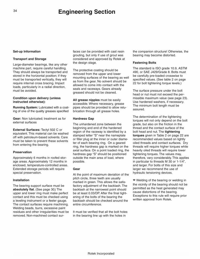
Rotek Incorporated
Engineering Section
Set-up Information
Transport and Storage
Large-diameter bearings, like any othermachine part, require careful handling.They should always be transported andstored in the horizontal position; if theymust be transported vertically, they willrequire internal cross bracing. Impactloads, particularly in a radial direction,must be avoided.
Condition upon delivery (unlessinstructed otherwise):
Running System: Lubricated with a coat-ing of one of the quality greases specified
Gear: Non lubricated; treatment as forexternal surfaces
External Surfaces: Tectyl 502 C orequivalent. This material can be washedoff with petroleum-based solvents. Caremust be taken to prevent these solventsfrom entering the bearing.
Preservation
Approximately 6 months in roofed stor-age areas. Approximately 12 months inenclosed, temperature-controlled areas.Extended storage periods will requirespecial preservation.
Installation
The bearing support surface must beabsolutely flat. (See page 30.) Theupper and lower ring must make perfectcontact and this must be checked usinga leveling instrument or a feeler gauge.The contact surfaces require machining.Welding beads, burrs, excessive paintresidues and other irregularities must beremoved. Non-machined contact sur-
faces can be provided with cast resingrouting, but only if use of grout wasconsidered and approved by Rotek atthe design stage.
The protective coating should beremoved from the upper and lowermounting surfaces of the bearing as wellas from the gear. No solvent should beallowed to come into contact with theseals and raceways. Gears alreadygreased should not be cleaned.
All grease nipples must be easilyaccessible. Where necessary, greasepipes should be provided to allow relu-brication through all grease holes.
Hardness Gap
The unhardened zone between thebeginning and end of the hardenedregion of the raceway is identified by astamped letter “S” near the nameplateor filler plug at the inner or outer diame-ter of each bearing ring. On a gearedring, the hardness gap is marked on theaxial surface. On a point loaded ring, thehardness gap “S” should be positionedoutside the main area of load, wherepossible.
Gear
At the point of maximum deviation of thepitch circle, three teeth are usuallymarked in green. This allows the satis-factory adjustment of the backlash. Thebacklash at the narrowest point shouldbe at least 0.03/DP. After the final tight-ening of the bolts of the bearing thebacklash should be checked around theentire circumference.
It must be verified that all the bolt holesin the bearing line up with the holes in
the companion structure! Otherwise, thebearing may become distorted.
Fastening Bolts
The standard is ISO grade 10.9, ASTM490, or SAE J429/Grade 8. Bolts mustbe carefully pre-loaded crosswise tospecified values. (See table 2 on page22 for bolt tightening torque levels.)
The surface pressure under the bolthead or nut must not exceed the per-missible maximum value (see page 23).Use hardened washers, if necessary.The minimum bolt length must beassured.
The determination of the tighteningtorques will not only depend on the boltgrade, but also on the friction in thethread and the contact surface of thebolt head and nut. The tighteningtorques given in Table 2 on page 22 arerecommended values based on lightlyoiled threads and contact surfaces. Drythreads will require higher torques whileheavily oiled threads will require lowertightening torques. The values may,therefore, vary considerably. This appliesin particular to threads M 30 or 1-1/4”,and larger. For bolts of this size andlarger we recommend the use ofhydraulic tensioning devices.
� Welding of the bearing or welding inthe vicinity of the bearing should not bepermitted as the heat generated maycause distortions of the bearing.Exceptions to this rule will require priorwritten approval from Rotek.
34
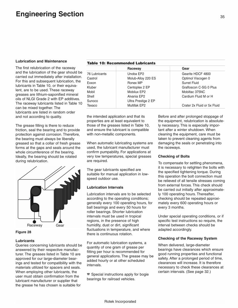
35
Rotek Incorporated
Lubrication and Maintenance
The first relubrication of the racewayand the lubrication of the gear should becarried out immediately after installation.For this and subsequent lubrication, thelubricants in Table 10, or their equiva-lent, are to be used. These racewaygreases are lithium-saponified mineraloils of NLGI Grade 2 with EP additives.The raceway lubricants listed in Table 10can be mixed together. The lubricants are listed in random order and not according to quality.
The grease filling is there to reduce friction, seal the bearing and to provideprotection against corrosion. Therefore,the bearing must always be liberallygreased so that a collar of fresh greaseforms at the gaps and seals around thewhole circumference of the bearing.Ideally, the bearing should be rotatedduring relubrication.
Figure 28
LubricantsQueries concerning lubricants should beanswered by their respective manufac-turer. The greases listed in Table 10 areapproved for our large-diameter bear-ings and tested for compatibility with thematerials utilized for spacers and seals.When employing other lubricants, theuser must obtain confirmation from thelubricant manufacturer or supplier thatthe grease he has chosen is suitable for
the intended application and that itsproperties are at least equivalent tothose of the greases listed in Table 10,and ensure the lubricant is compatiblewith non-metallic components.
When automatic lubricating systems areused, the lubricant manufacturer mustconfirm pumpability. For applications atvery low temperatures, special greasesare required.
The gear lubricants specified are suitable for manual application in low-speed outdoor use.
Lubrication Intervals
Lubrication intervals are to be selectedaccording to the operating conditions;generally every 100 operating hours, forball bearings and every 50 hours forroller bearings. Shorter lubrication intervals must be used in tropicalregions, in the presence of high humidity, dust or dirt, significant fluctuations in temperature, and wherethere is continuous rotation.
For automatic lubrication systems, aquantity of one gram of grease per fitting per hour is recommended for general applications. The grease may beadded hourly or at other scheduledintervals.
� Special instructions apply for bogie bearings for railroad vehicles.
Before and after prolonged stoppage ofthe equipment, relubrication is absolute-ly necessary. This is especially impor-tant after a winter shutdown. Whencleaning the equipment, care must betaken to prevent cleaning agents fromdamaging the seals or penetrating intothe raceways.
Checking of Bolts
To compensate for settling phenomena,it is necessary to retighten the bolts withthe specified tightening torque. Duringthis operation the bolt connection mustbe relieved of all tensile stresses comingfrom external forces. This check shouldbe carried out initially after approximate-ly 100 operating hours. Thereafter,checking should be repeated approxi-mately every 600 operating hours orevery 3 months.
Under special operating conditions, or ifspecific test instructions so require, theinterval between checks should beadapted accordingly.
Checking of the Raceway System
When delivered, large-diameter bearings have clearances which ensuregood running properties and functionalsafety. After a prolonged period of time,clearances will increase. It is thereforenecessary to check these clearances atcertain intervals. (See page 32.)
Engineering Section
Table 10: Recommended LubricantsRaceway Gear
76 Lubricants Unoba EP2 Gearite HDCF 4800Castrol Molub-Alloy 220 ES Optimol Viscogen 0Exxon Ronex MP Surret FluidKluber Centoplex 2 EP Grafloscon C-SG 0 PlusMobil Mobilux EP2 Mobiltac 375NCShell Alvania EP2 Cardium Fluid M or HSunoco Ultra Prestige 2 EPTexaco Multifak EP2 Crater 2x Fluid or 5x Fluid
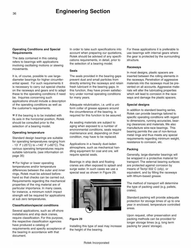
Rotek Incorporated
Engineering Section
Operating Conditions and SpecialRequirements
The data contained in this catalogrefers to bearings with applications involving oscillating motions or slewingmovements.
It is, of course, possible to use large-diameter bearings for higher circumfer-ential speed. For such requirements itis necessary to carry out special checkson the raceways and gears and to adaptthese to the operating conditions if needbe. Inquiries concerning such applications should include a descriptionof the operating conditions as well asthe customer’s requirements.
� If the bearing is to be installed with its axis in the horizontal position, Rotekshould be consulted prior to the selection of a bearing model.
Operating temperature
Standard design bearings are suitablefor operating temperatures ranging from- 13˚ F (-25°C) to +140˚ F (+60°C). Thevarious operating temperatures requiresuitable lubricants. (see information onpage 35)
� For higher or lower operating temperatures and/or temperature differences between the outer and innerrings, Rotek must be advised before-hand so that checks can be carried out.Requirements regarding the mechanicalproperties of the ring material are of particular importance. In many cases,for instance, a minimum notch impactstrength will be required for applicationsat sub zero temperatures.
Classification/special conditions
Several applications, such as off-shoreinstallations and ship deck cranes,require classification. For this purpose,the respective classification agencieshave produced a catalog of requirements and specify acceptance ofthe bearing in accordance with that document.
In order to take such specifications intoaccount when preparing our quotations,Rotek should be advised of any specifi-cations requirements, in detail, prior tothe selection of a bearing model.
Seals
The seals provided in the bearing gapsprevent dust and small particles fromdirectly entering the raceways and retainfresh lubricant in the bearing gaps. Inthis function, they have proven satisfac-tory under normal operating conditionsfor many years.
Adequate relubrication, i.e. until a uni-form collar of grease appears aroundthe circumference of the bearing, isrequired for this function to be assured.
As sealing materials are subject toaging when exposed to a number ofenvironmental conditions, seals requiremaintenance and, depending on theircondition, may have to be replaced.
Applications in a heavily dust-ladenatmosphere, such as mechanical han-dling equipment for coal and ore, willrequire special seals.
Bearings in ship deck and floatingcranes are often exposed to splash andsurge water. In such cases we use aspecial seal as shown in Figure 29.
Figure 29
Installing this type of seal may increasethe height of the bearing.
For these applications it is preferable touse bearings with internal gears wherethe gear is protected by the surroundingstructure.
Raceways
In most designs, plastic spacers areinserted between the rolling elements inthe raceways. Penetration of aggressivematerials into the raceways must be pre-vented on all accounts. Aggressive mate-rials will alter the lubricating propertieswhich will lead to corrosion in the race-ways and damage the plastic spacers.
Special designs
In addition to standard bearing series,Rotek can provide bearings tailored tospecific operating conditions with regardto dimensions, running accuracies, bear-ing clearances and materials. We alsomanufacture wire-race bearings. Thisbearing permits the use of non-ferrousmetal rings and thus meets any specialrequirements regarding minimum weight,resistance to corrosion, etc.
Packing
Generally, large-diameter bearings willbe wrapped in a protective material fortransport. The external bearing surfacesare protected against corrosion bymeans of Tectyl 502 C (oily), or equivalent, and by filling the racewayswith lithium-based grease.
The method of transport will determinethe type of packing used (e.g. pallets,crates).
Standard packing will provide adequateprotection for storage times of up to oneyear in enclosed, temperature controlledareas.
Upon request, other preservation andpacking methods can be provided forlonger storage times (e.g. long termpacking for years’ storage).
36
37
Rotek Incorporated
Engineering Section
Bearing Design Worksheet Instructions
Bearing design assistance is availablefrom Rotek without charge
Rotek’s Application Engineering departmentis available, without charge, to assist designengineers in the design or selection of anappropriate large-diameter bearing for theirspecific application.
To facilitate this process, this catalog includesa Bearing Design Worksheet on the twopages that follow. It provides a convenientmethod of summarizing the informationrequired to engineer a bearing specific toyour needs.
How to use the Bearing Design Worksheet
Here are the suggested procedures for theuse of the Bearing Design Worksheet:
1. Photocopy the Design Worksheetappearing on pages 38 and 39.
2. Complete the Design Worksheet,providing requested information foryour application.
� Feel free to contact Rotek at 1-800-221-8043 with any questionsyou may have.
3. Include any drawings or loadsketches that might assist in providinga detailed explanation of your application.
4. Send the completed DesignWorksheet and any additional information to:
Rotek Incorporated1400 Chillicothe RoadAurora, OH 44202
or fax the form and information to:
Rotek Application Engineering at,330/562-2709.
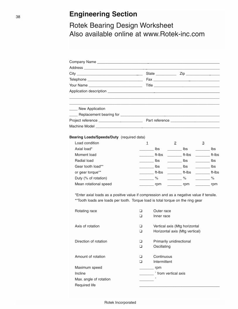
Rotek Incorporated
Engineering Section
Rotek Bearing Design WorksheetAlso available online at www.Rotek-inc.com
Company Name ____________________________________________________________
Address ___________________________________________________________________
City _________________________________ State __________ Zip _________________
Telephone ___________________________ Fax _________________________________
Your Name __________________________ Title ________________________________
Application description _______________________________________________________
_________________________________________________________________________
_________________________________________________________________________
____ New Application
____ Replacement bearing for _________________________________________________
Project reference ______________________ Part reference ________________________
Machine Model _____________________________________________________________
Bearing Loads/Speeds/Duty (required data)
Load condition 1 2 3
Axial load* _______ lbs _______ lbs _______ lbs
Moment load _______ ft-lbs _______ ft-lbs _______ ft-lbs
Radial load _______ lbs _______ lbs _______ lbs
Gear tooth load** _______ lbs _______ lbs _______ lbs
or gear torque** _______ ft-lbs _______ ft-lbs _______ ft-lbs
Duty (% of rotation) _______ % _______ % _______ %
Mean rotational speed _______ rpm _______ rpm _______ rpm
*Enter axial loads as a positive value if compression and as a negative value if tensile.
**Tooth loads are loads per tooth. Torque load is total torque on the ring gear
Rotating race ❑ Outer race❑ Inner race
Axis of rotation ❑ Vertical axis (Mtg horizontal❑ Horizontal axis (Mtg vertical)
Direction of rotation ❑ Primarily unidirectional❑ Oscillating
Amount of rotation ❑ Continuous❑ Intermittent
Maximum speed _______ rpm
Incline _______ ˚ from vertical axis
Max. angle of rotation _______ ˚
Required life _______________________________________
38

39Space Limits Preferred Range
Outside diameter _______ inches _______ inches (max.)
Inside diameter _______ inches _______ inches (min.)
Overall height _______ inches _______ inches (max.)
Raceway diameter _______ inches _______ inches (min.)
_______ inches (max.)
Gearing (include drawing of pinion if possible)
❑ External gear ❑ Internal gear ❑ No gearing
Tooth form __________________________________________________________
Required reduction ratio _______________________________________________
Number of pinion teeth ________________________________________________
Number of pinion drives _______________________________________________
Bolts
❑ SAE only ❑ Metric only ❑ SAE or Metric
Outer race bolt holes ❑ Thru
❑ Thru and counterbored
❑ Tapped
❑ Tapped and counterbored
❑ No preference
Inner race bolt holes ❑ Thru
❑ Thru and counterbored
❑ Tapped
❑ Tapped and counterbored
❑ No preference
Special requirements (check where applicable)
❑ Manual rotation
❑ Seals required
❑ Extremely dirty
❑ High temperature (>125˚F) Max temperature _______ ˚F
❑ API,ABS,DNV or Lloyds certification required
❑ Precision/preloaded bearing (Please provide details below)
❑ Precision gearing. Gear quality _______________________________________
❑ Rolling elements must be caged. No spacers.
❑ No grease lubrication
❑ Oil lubrication
❑ Specific location of grease ports
Outer race ❑ OD
❑ Mounting side
❑ Non-mounting side
Inner race ❑ ID
❑ Mounting side
❑ Non-mounting side
Additional Comments ________________________________________________________
_________________________________________________________________________
_________________________________________________________________________
For the most economical and accurate proposal, please attach applicable drawings and loadsketches. Mail or fax to: Rotek Incorporated, Attn: Application Engineering Department,1400 Chillicothe Road, Aurora, OH 44202. Fax: 330/562-2709 � 800/221-8043.

Rotek Incorporated
Series 1000 Econo-TrakTM Bearings
Rotek Series 1000 bearings comprise aline of inexpensive, versatile rolled-ringbearings made with unhardened,machined raceways. Designed for useas fifth wheels for trailers and farm wag-ons, Series 1000 bearings are availablefrom stock in diameters from 12 to 42inches. Thrust capacities range from1650 to 35,200 pounds for fifth-wheelapplications.
Assembled with a full complement ofchrome-alloy steel balls without spacers,this series of Econo-Trak bearings hasproved effective for many low-speed, bi-directional industrial applications whererotation is intermittent and loads arecompressive. Series 1000 bearings maynot be used in tension. Lift-off protectionprovided by the bearing design is onlyintended to keep the bearing together forhandling and minor uplifts.
� If your application requires a bearing that can be tension loaded, con-tact Rotek.
Each Series 1000 bearing is a completeassembly in itself, requiring no additionalcomponents or accessories other thanmounting fasteners. The bearing may bebolted directly to flat and rigid mountingstructures.
The vertical, profiled web of the bearingmust be supported to assure direct anduniform load transmission to the ballraceways. At least 50 percent of the
peripheral bearing flange mounting sur-faces must be supported. Load bearingzones should be roughly equally spacedand (for fifth-wheel applications) orientedin the direction of travel and at rightangles to travel. Total mounting surfaceout-of-flatness must not exceed .05 inch-es. The bearings in the turntables mustbe fastened with SAE grade 5 (or better)fasteners. The horizontal forces resultingfrom acceleration or deceleration mustbe transmitted by stops welded (or oth-erwise permanently fixed) to the matingstructures so as to relieve the load onthe bolts in the radial direction. The bear-ing must never be welded to the matingstructure.
For fifth-wheel applications
Bearings may be applied up to the pub-lished thrust capacity limits. (See thedimensional tables on page 41.) Modelswith the prefix designation “M4” are nor-mally used for low-speed applicationssuch as farm trailers. They provide ade-quate radial capacity for decelerationrates up to 5 ft./sec2. The other modelsare recommended for normal highwayservice and provide adequate capacityfor radial loading resulting from decelera-tion rates up to 11.5 ft./sec2.
To select a Series 1000 fifth-wheel bear-ing, merely determine the maximumweight which will be carried, and thenselect from the fifth-wheel capacity ratingon page 41.
Other Applications
Series 1000 bearing have been suc-cessfully applied to certain tasks ordinar-ily thought appropriate only for Series2100 bearings. If the application involvespositioning-type, intermittent rotation andthe center of gravity remains within thediameter of the bearing, a Series 1000bearing may prove acceptable at a sub-stantial savings in cost.
For applications where frictional torqueis critical, such as turntables rotated
manually, it is recommended that one ormore prototype bearings be procuredand tested before committing them to aproduction design. If low-friction perform-ance of the first unit is critical, anotherstyle of bearing may be more suitable.
� Call Rotek for assistance.
The recommended maximum racewayvelocity for Series 1000 bearings is 100feet per minute.
Published thrust capacity ratings shouldbe derated by a factor of 2.7 for turntableapplications that are manually rotated.� If the center of gravity is off the center of rotation, contact Rotekengineering for assistance in sizing thebearing. Tension loaded applications arenot permissible. (See page 14 for bearing load definitions.)
� Note: All capacity curves and ratings assume that the bearing is mounted in compression. If bearing is mounted in tension, call us.
40

41
Example 1
Cart is symmetrical — weight is equally distributedon front and rear axles. Bearing load is thus half oftotal, or 3250 lb.
Select bearing according to rated fifth-wheel capaci-ty. Model M4-22P4 has capacity of 3300 lb., whichexceeds required 3250 lb.
Example 2
Since axles are not symmetrically located, it is necessary to compute load on bearing. This may beeasily done by summing moments about the centerline of the rear suspension as follows:
Weight of body and load x 11’ = Force on front axle x 24’
52,000 x 11’F = —————— = 23,800 lb.
24’
Appropriate bearing choice would be Model M6-39P1, which has capacity of 26,400 lb.
Airport baggage cartCart: 1500 lb.Maximum Load: 5000 lb.Total: 6500 lb.
Highway trailerTrailer Weight: (excluding suspensions and wheels) 14,000 lb.Weight of Maximum Load: 38,000 lb.Total Weight: 52,000 lb.
ThrustModel Model Outline Dimensions (inches) Mounting Holes* No of Capacity (lbs)
No. No. Wt. HolesLess Mtg. With Mtg. (lbs) OBC IBC DIA Per Race Fifth
Holes Holes OD ID IO OI HT A (in) (in) (in) Wheel
M4-12P4 M4-12P4Z 24 15.9 9.3 13.6 11.6 1.65 .32 14.75 10.25 9/16 6 1,650M4-16P4 M4-16P4Z 33 19.8 13.2 17.6 15.5 1.65 .32 18.63 14.13 9/16 6 1,980M4-22P4 M4-22P4Z 44 25.7 19.1 23.5 21.4 1.65 .32 24.63 20.00 9/16 6 3,300M4-26P4 M4-26P4Z 51 29.7 23.1 27.4 25.4 1.65 .32 28.50 24.00 9/16 8 3,960M4-30P4 M4-30P4Z 60 33.6 27.0 31.3 29.3 1.65 .32 32.50 28.00 9/16 8 5,280M4-34P4 M4-34P4Z 66 37.6 30.9 35.3 33.2 1.65 .32 36.38 31.88 9/16 8 6,600M4-38P4 M4-38P4Z 75 41.5 34.9 39.2 37.2 1.65 .32 40.25 35.75 9/16 8 7,920M5-16P1 M5-16P1Z 40 19.6 12.4 17.1 15.0 1.9 .32 18.50 13.50 9/16 8 3,960M5-22P1 M5-22P1Z 50 25.6 18.3 23.0 20.9 1.9 .32 24.50 19.50 9/16 8 5,500M5-26P1 M5-26P1Z 60 29.5 22.2 26.9 24.8 1.9 .32 28.38 23.50 9/16 8 6,600M5-30P1 M5-30P1Z 70 33.5 26.2 30.9 28.8 1.9 .32 32.38 27.25 9/16 8 7,700M5-34P1 M5-34P1Z 75 37.4 30.1 34.8 32.7 1.9 .32 36.25 31.13 9/16 8 8,800M5-38P1 M5-38P1Z 85 41.3 34.1 38.7 36.7 1.9 .32 40.13 35.13 9/16 8 9,900Tolerances +.313 +.125
-.200 -.313 ±.125 ±.080 ±.125 ±.063 ±.012 ±.012
M5-31P1 M5-31P1Z 95 35.2 30.0 34.6 30.8 3.2 .35 34.00 33.50 9/16 8 15,400M5-36P1 M5-36P1Z 110 40.0 34.7 39.4 35.6 3.15 .35 38.75 38.25 9/16 8 18,000M5-40P1 M5-40P1Z 125 43.5 38.3 42.9 39.1 3.2 .35 42.38 41.75 9/16 8 19,800M6-35P1 M6-35P1Z 145 39.7 33.9 39.4 34.8 3.5 .39 38.38 38.00 9/16 8 22,000M6-39P1 M6-39P1Z 165 43.6 37.8 43.3 38.8 3.5 .39 42.25 41.75 11/16 8 26,400M7-39P1 M7-39P1Z 163 43.6 37.7 43.3 38.9 3.5 .39 42.25 41.75 11/16 12 30,800M7-42P1 M7-42P1Z 174 47.6 41.6 47.2 42.8 3.5 .39 46.25 45.75 11/16 12 35,200Tolerances +.313 +.31
-.125 ±.080 -.125 ±.080 ±.125 ±.063 ±.012 ±.012
*Note: Standard Series 1000 bearings furnished without mounting holes. For bearings complete with mounting holes, add suffix “Z” to model number. Example: Model M4-12P4 complete with mounting holes becomes Model M4-12P4Z. There are 4 grease fittings, approximately equally spaced, that press-fit into a 1/4 inch diameter hole as shown. Rotek recommends consulting pages 12 - 36 for additional information that must be reviewed prior to bearing selection.
Series 1000 Econo-TrakTM Bearings
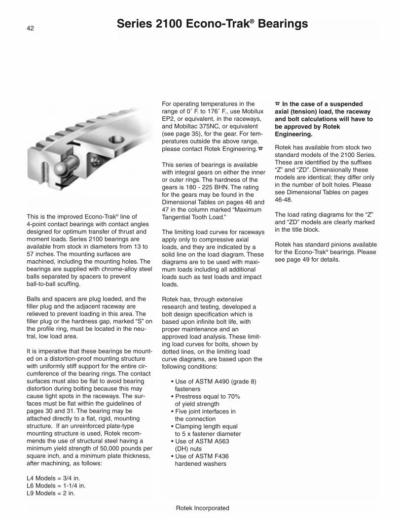
Rotek Incorporated
Series 2100 Econo-Trak® Bearings
This is the improved Econo-Trak® line of 4-point contact bearings with contact anglesdesigned for optimum transfer of thrust andmoment loads. Series 2100 bearings areavailable from stock in diameters from 13 to57 inches. The mounting surfaces aremachined, including the mounting holes. Thebearings are supplied with chrome-alloy steelballs separated by spacers to prevent ball-to-ball scuffing.
Balls and spacers are plug loaded, and thefiller plug and the adjacent raceway arerelieved to prevent loading in this area. Thefiller plug or the hardness gap, marked “S” onthe profile ring, must be located in the neu-tral, low load area.
It is imperative that these bearings be mount-ed on a distortion-proof mounting structurewith uniformly stiff support for the entire cir-cumference of the bearing rings. The contactsurfaces must also be flat to avoid bearingdistortion during bolting because this maycause tight spots in the raceways. The sur-faces must be flat within the guidelines ofpages 30 and 31. The bearing may beattached directly to a flat, rigid, mountingstructure. If an unreinforced plate-typemounting structure is used, Rotek recom-mends the use of structural steel having aminimum yield strength of 50,000 pounds persquare inch, and a minimum plate thickness,after machining, as follows:
L4 Models = 3/4 in.L6 Models = 1-1/4 in.L9 Models = 2 in.
42
For operating temperatures in therange of 0˚ F. to 176˚ F., use MobiluxEP2, or equivalent, in the raceways,and Mobiltac 375NC, or equivalent(see page 35), for the gear. For tem-peratures outside the above range,please contact Rotek Engineering.�
This series of bearings is availablewith integral gears on either the inneror outer rings. The hardness of thegears is 180 - 225 BHN. The ratingfor the gears may be found in theDimensional Tables on pages 46 and47 in the column marked “MaximumTangential Tooth Load.”
The limiting load curves for racewaysapply only to compressive axialloads, and they are indicated by asolid line on the load diagram. Thesediagrams are to be used with maxi-mum loads including all additionalloads such as test loads and impactloads.
Rotek has, through extensiveresearch and testing, developed abolt design specification which isbased upon infinite bolt life, withproper maintenance and anapproved load analysis. These limit-ing load curves for bolts, shown bydotted lines, on the limiting loadcurve diagrams, are based upon thefollowing conditions:
• Use of ASTM A490 (grade 8) fasteners
• Prestress equal to 70% of yield strength
• Five joint interfaces in the connection
• Clamping length equal to 5 x fastener diameter
• Use of ASTM A563 (DH) nuts
• Use of ASTM F436 hardened washers
� In the case of a suspended axial (tension) load, the racewayand bolt calculations will have tobe approved by RotekEngineering.
Rotek has available from stock twostandard models of the 2100 Series.These are identified by the suffixes“Z” and “ZD”. Dimensionally thesemodels are identical; they differ onlyin the number of bolt holes. Pleasesee Dimensional Tables on pages46-48.
The load rating diagrams for the “Z”and “ZD” models are clearly markedin the title block.
Rotek has standard pinions availablefor the Econo-Trak® bearings. Pleasesee page 49 for details.
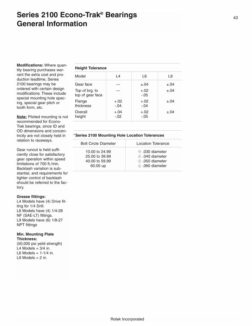
43
Rotek Incorporated
Height Tolerance
Model L4 L6 L9
Gear face — ±.04 ±.04
Top of brg. to — +.02 ±.04top of gear face -.05
Flange +.02 +.02 ±.04thickness -.04 -.04
Overall +.04 +.02 ±.04height -.02 -.05
Modifications: Where quan-tity bearing purchases war-rant the extra cost and pro-duction leadtime, Series2100 bearings may beordered with certain designmodifications. These includespecial mounting hole spac-ing, special gear pitch ortooth form, etc.
Note: Piloted mounting is notrecommended for Econo-Trak bearings, since ID andOD dimensions and concen-tricity are not closely held inrelation to raceways.
Gear runout is held suffi-ciently close for satisfactorygear operation within speedlimitations of 700 ft./min.Backlash variation is sub-stantial, and requirements fortighter control of backlashshould be referred to the fac-tory.
Grease fittings:L4 Models have (4) Drive fit-ting for 1/4 Drill.L6 Models have (4) 1/4-28NF (SAE-LT) fittings.L9 Models have (6) 1/8-27NPT fittings
Min. Mounting PlateThickness:(50,000 psi yeild strength)L4 Models = 3/4 in.L6 Models = 1-1/4 in.L9 Models = 2 in.
Series 2100 Econo-Trak® BearingsGeneral Information
*Series 2100 Mounting Hole Location Tolerances
Bolt Circle Diameter Location Tolerance
10.00 to 24.99 .030 diameter25.00 to 39.99 .040 diameter40.00 to 59.99 .050 diameter
60.00 up .060 diameter

Rotek Incorporated
These load diagrams defineboth bearing raceway (i.e.solid line) and bolt (i.e. dottedline) limiting load ratingcurves for the Series 2100Econo-Trak bearings.
Z and ZD model limiting loadrating curves reflect differences in the number ofmounting holes utilized.
Higher capacities are achievable with modified boltpatterns, or by applying a“full” section interchangeablebearing. However, thesemodifications can only bearranged with prior Rotektechnical approval. Pleasecall 800/221-8043 for technical assistance.
Pages 46 thru 48 dimension-ally describe bearing crosssections for the above mentioned bearings.
Maximum Static Bearing Capacity ForSeries 2100 Econo-Trak® Bearings
44

45
Rotek Incorporated
Maximum Static Bearing Capacity ForSeries 2100 Econo-Trak® Bearings
These load diagrams defineboth bearing raceway (i.e.solid line) and bolt (i.e. dottedline) limiting load ratingcurves for the Series 2100Econo-Trak bearings.
Higher capacities are achievable with modified boltpatterns, or by applying a“full” section interchangeable
bearing. However, thesemodifications can only bearranged with prior Rotektechnical approval. Pleasecall 800/221-8043 for technical assistance.
Pages 46 thru 48 dimension-ally describe bearing crosssections for the above mentioned bearings.

Rotek Incorporated
Series 2100 Econo-Trak® Bearings WithInternal Gears
46
Fig. 1 Fig. 2
Outline Dimensions (inches) Mounting Holes* Gear Data
No. No. DP No. Max.Model No. Wt. OD ID IO OI IE OE OBC Holes IBC Holes 20˚ of Tangential
(lbs) (in) OBC (in) IBC PD Stub Teeth ToothLoad
L6-16N9Z 59 20.39 12.85 16.24 16.36 — 17.83 19.25 8 14.88 12 13.25 4 53 6,090L6-16N9ZD 59 20.39 12.85 16.24 16.36 — 17.83 19.25 16 14.88 12 13.25 4 53 6,090L6-22N9Z 81 25.51 17.60 21.36 21.48 — 22.95 24.38 10 19.63 15 18.00 4 72 6,090L6-22N9ZD 81 25.51 17.60 21.36 21.48 — 22.95 24.38 20 19.63 16 18.00 4 72 6,090L6-25N9Z 96 29.45 21.60 25.30 25.41 — 26.89 28.38 12 23.63 18 22.00 4 88 6,090L6-25N9ZD 96 29.45 21.60 25.30 25.41 — 26.89 28.38 24 23.63 18 22.00 4 88 6,090L6-29N9Z 112 33.39 25.60 29.23 29.35 — 30.83 32.25 15 27.63 18 26.00 4 104 6,090L6-29N9ZD 112 33.39 25.60 29.23 29.35 — 30.83 32.25 24 27.63 20 26.00 4 104 6,090L6-33N9Z 133 37.32 29.13 33.17 33.29 — 34.76 36.25 18 31.50 18 29.67 3 89 8,120L6-33N9ZD 133 37.32 29.13 33.17 33.29 — 34.76 36.25 28 31.50 20 29.67 3 89 8,120L6-37N9Z 144 41.26 33.13 37.11 37.22 — 38.70 40.13 18 35.50 20 33.67 3 101 8,120L6-37N9ZD 144 41.26 33.13 37.11 37.22 — 38.70 40.13 32 35.50 22 33.67 3 101 8,120L6-43N9Z 167 47.17 39.13 43.01 43.13 — 44.61 46.00 18 41.50 24 39.67 3 119 8,120L6-43N9ZD 167 47.17 39.13 43.01 43.13 — 44.61 46.00 32 41.50 24 39.67 3 119 8,120Tolerances ±.14 +.03 ±.14 ±.14 ±.14
L9-38N9Z 351 43.31 32.16 37.66 37.54 — 40.04 41.75 30 35.00 30 32.80 2.5 82 15,400L9-42N9Z 388 47.24 36.16 41.59 41.48 — 43.98 45.75 30 39.00 30 36.80 2.5 92 15,400L9-46N9Z 433 51.18 39.76 45.53 45.41 — 47.91 49.75 36 43.00 36 40.40 2.5 101 15,400L9-49N9Z 467 55.12 43.76 49.47 49.35 — 51.85 53.63 42 47.00 42 44.40 2.5 111 15,400L9-53N9Z 505 59.06 47.76 53.41 53.29 — 55.79 57.63 42 51.00 42 48.40 2.5 121 15,400L9-57N9Z 538 62.99 51.76 57.34 57.22 — 59.72 61.50 48 55.00 48 52.40 2.5 131 15,400Tolerances ±.14 +.03 ±.14 ±.14 ±.14
Fig
ure
2F
igu
re 1
Model numbers beginning with L9 have six equally spaced grease fittings; all others listed have four.*Thread depth on L6 bearing: 0.75 inches. Thread depth on L9 bearings: 1.13 inches.Gear tooth hardness 180 BHN minimum.
Rotek recommends consulting pages 12 - 36 for additional information that must be reviewed prior to bearing selection.

47
Outline Dimensions (inches) Mounting Holes* Gear Data
No. No. DP No. Max.Model No. Wt. OD ID IO OI IE OE OBC Holes IBC Holes 20˚ of Tangential
(lbs) (in) OBC (in) IBC PD Stub Teeth ToothLoad
L6-16E9Z 65 19.90 11.97 16.24 16.36 14.76 — 18.00 8 13.13 12 19.50 4 78 5,740L6-16E9ZD 65 19.90 11.97 16.24 16.36 14.76 — 18.00 10 13.13 24 19.50 4 78 5,740L6-22E9Z 86 25.15 17.09 21.36 21.48 19.88 — 23.25 12 18.13 15 24.75 4 99 5,852L6-22E9ZD 86 25.15 17.09 21.36 21.48 19.88 — 23.25 14 18.13 28 24.75 4 99 5,852L6-25E9Z 103 29.15 21.02 25.30 25.41 23.82 — 27.25 15 22.13 18 28.75 4 115 5,894L6-25E9ZD 103 29.15 21.02 25.30 25.41 23.82 — 27.25 16 22.13 32 28.75 4 115 5,894L6-29E9Z 115 32.90 24.96 29.23 29.35 27.76 — 31.00 18 26.13 18 32.50 4 130 5,950L6-29E9ZD 115 32.90 24.96 29.23 29.35 27.76 — 31.00 18 26.13 32 32.50 4 130 5,950L6-33E9Z 137 37.20 28.90 33.17 33.29 31.69 — 35.00 18 30.00 18 36.67 3 110 7,840L6-33E9ZD 137 37.20 28.90 33.17 33.29 31.69 — 35.00 18 30.00 36 36.67 3 110 7,840L6-37E9Z 153 41.20 32.83 37.11 37.22 35.63 — 38.88 18 34.00 20 40.67 3 122 7,896L6-37E9ZD 153 41.20 32.83 37.11 37.22 35.63 — 38.88 20 34.00 40 40.67 3 122 7,896L6-43E9Z 170 46.87 38.74 43.01 43.13 41.54 — 44.63 20 39.88 24 46.33 3 139 7,952L6-43E9ZD 170 46.87 38.74 43.01 43.13 41.54 — 44.63 22 39.88 40 46.33 3 139 7,952Tolerances -.03 ±.10 ±.14 ±.14 ±.14
L9-38E9Z 360 43.04 31.69 37.66 37.54 35.16 — 40.00 30 33.25 30 42.40 2.5 106 14,700L9-42E9Z 404 47.04 35.63 41.59 41.48 39.09 — 44.00 30 37.13 30 46.40 2.5 116 14,770L9-46E9Z 445 51.04 39.57 45.53 45.41 43.03 — 48.00 36 41.13 36 50.40 2.5 126 14,840L9-49E9Z 485 55.04 43.50 49.47 49.35 46.97 — 52.00 42 45.00 42 54.40 2.5 136 14,910L9-53E9Z 529 59.04 47.44 53.41 53.29 50.91 — 56.00 42 49.00 42 58.40 2.5 146 14,980L9-57E9Z 541 62.64 51.38 57.34 57.22 54.84 — 59.63 48 52.88 48 62.00 2.5 155 15,050Tolerances -.03 ±.14 ±.14 ±.14 ±.14
Model numbers beginning with L9 have six equally spaced grease fittings; all others listed have four.
*Thread depth on L6 bearing: 0.75 inches. Thread depth on L9 bearings: 1.13 inches.
Gear tooth hardness 180 BHN minimum.
Rotek recommends consulting pages 12 - 36 for additional information that must be reviewed prior to bearing selection.
Fig
ure
4F
igu
re 3
Fig. 3 Fig. 4
Series 2100 Econo-Trak® Bearings WithExternal Gears
Rotek Incorporated
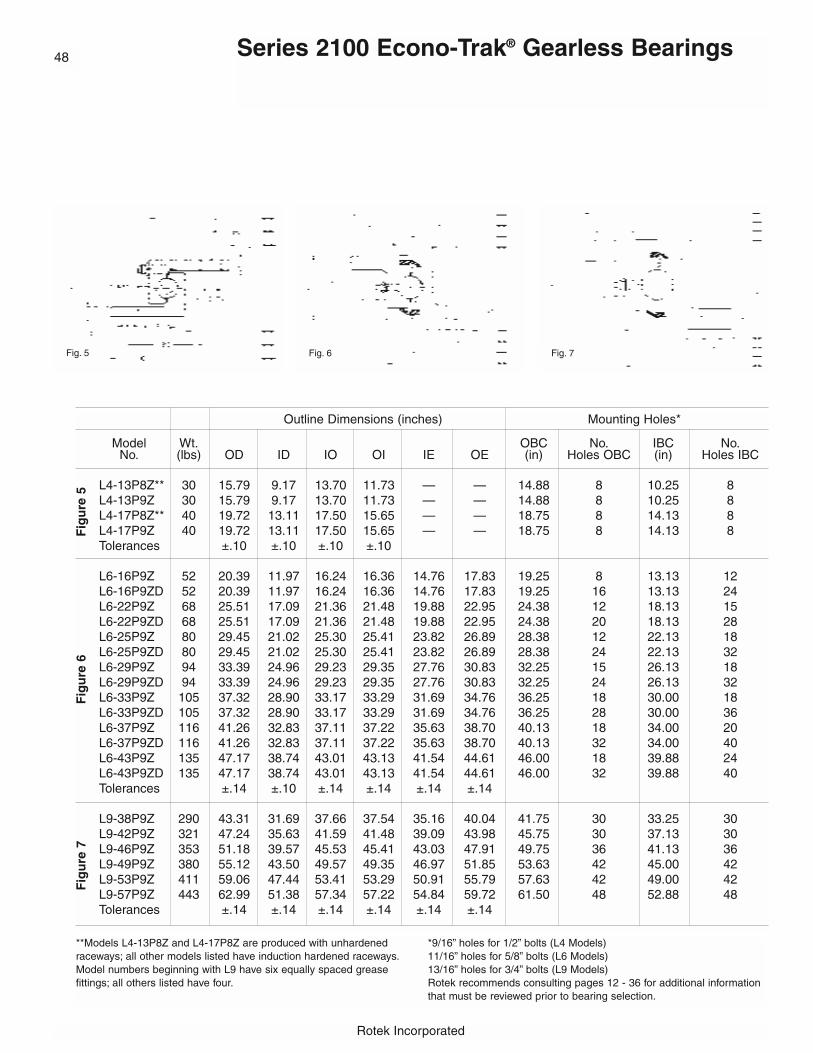
Rotek Incorporated
Series 2100 Econo-Trak® Gearless Bearings
Outline Dimensions (inches) Mounting Holes*
Model Wt. OBC No. IBC No.No. (lbs) OD ID IO OI IE OE (in) Holes OBC (in) Holes IBC
L4-13P8Z** 30 15.79 9.17 13.70 11.73 — — 14.88 8 10.25 8L4-13P9Z 30 15.79 9.17 13.70 11.73 — — 14.88 8 10.25 8L4-17P8Z** 40 19.72 13.11 17.50 15.65 — — 18.75 8 14.13 8L4-17P9Z 40 19.72 13.11 17.50 15.65 — — 18.75 8 14.13 8Tolerances ±.10 ±.10 ±.10 ±.10
L6-16P9Z 52 20.39 11.97 16.24 16.36 14.76 17.83 19.25 8 13.13 12L6-16P9ZD 52 20.39 11.97 16.24 16.36 14.76 17.83 19.25 16 13.13 24L6-22P9Z 68 25.51 17.09 21.36 21.48 19.88 22.95 24.38 12 18.13 15L6-22P9ZD 68 25.51 17.09 21.36 21.48 19.88 22.95 24.38 20 18.13 28L6-25P9Z 80 29.45 21.02 25.30 25.41 23.82 26.89 28.38 12 22.13 18L6-25P9ZD 80 29.45 21.02 25.30 25.41 23.82 26.89 28.38 24 22.13 32L6-29P9Z 94 33.39 24.96 29.23 29.35 27.76 30.83 32.25 15 26.13 18L6-29P9ZD 94 33.39 24.96 29.23 29.35 27.76 30.83 32.25 24 26.13 32L6-33P9Z 105 37.32 28.90 33.17 33.29 31.69 34.76 36.25 18 30.00 18L6-33P9ZD 105 37.32 28.90 33.17 33.29 31.69 34.76 36.25 28 30.00 36L6-37P9Z 116 41.26 32.83 37.11 37.22 35.63 38.70 40.13 18 34.00 20L6-37P9ZD 116 41.26 32.83 37.11 37.22 35.63 38.70 40.13 32 34.00 40L6-43P9Z 135 47.17 38.74 43.01 43.13 41.54 44.61 46.00 18 39.88 24L6-43P9ZD 135 47.17 38.74 43.01 43.13 41.54 44.61 46.00 32 39.88 40Tolerances ±.14 ±.10 ±.14 ±.14 ±.14 ±.14
L9-38P9Z 290 43.31 31.69 37.66 37.54 35.16 40.04 41.75 30 33.25 30L9-42P9Z 321 47.24 35.63 41.59 41.48 39.09 43.98 45.75 30 37.13 30L9-46P9Z 353 51.18 39.57 45.53 45.41 43.03 47.91 49.75 36 41.13 36L9-49P9Z 380 55.12 43.50 49.57 49.35 46.97 51.85 53.63 42 45.00 42L9-53P9Z 411 59.06 47.44 53.41 53.29 50.91 55.79 57.63 42 49.00 42L9-57P9Z 443 62.99 51.38 57.34 57.22 54.84 59.72 61.50 48 52.88 48Tolerances ±.14 ±.14 ±.14 ±.14 ±.14 ±.14
Fig
ure
7F
igu
re 6
Fig
ure
5
48
Fig. 5 Fig. 6 Fig. 7
**Models L4-13P8Z and L4-17P8Z are produced with unhardenedraceways; all other models listed have induction hardened raceways.Model numbers beginning with L9 have six equally spaced grease fittings; all others listed have four.
*9/16” holes for 1/2” bolts (L4 Models)11/16” holes for 5/8” bolts (L6 Models)13/16” holes for 3/4” bolts (L9 Models)Rotek recommends consulting pages 12 - 36 for additional informationthat must be reviewed prior to bearing selection.
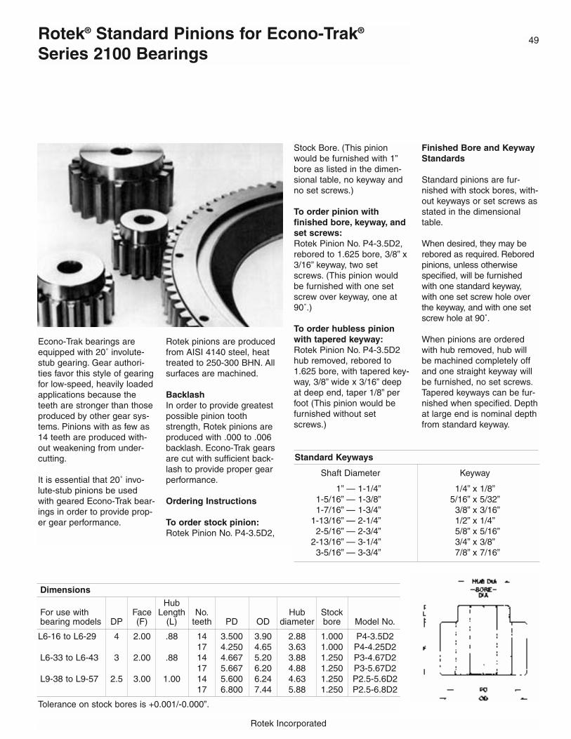
49
Rotek Incorporated
Econo-Trak bearings areequipped with 20˚ involute-stub gearing. Gear authori-ties favor this style of gearingfor low-speed, heavily loadedapplications because theteeth are stronger than thoseproduced by other gear sys-tems. Pinions with as few as14 teeth are produced with-out weakening from under-cutting.
It is essential that 20˚ invo-lute-stub pinions be usedwith geared Econo-Trak bear-ings in order to provide prop-er gear performance.
Rotek pinions are producedfrom AISI 4140 steel, heattreated to 250-300 BHN. Allsurfaces are machined.
BacklashIn order to provide greatestpossible pinion toothstrength, Rotek pinions areproduced with .000 to .006backlash. Econo-Trak gearsare cut with sufficient back-lash to provide proper gearperformance.
Ordering Instructions
To order stock pinion:Rotek Pinion No. P4-3.5D2,
Stock Bore. (This pinionwould be furnished with 1”bore as listed in the dimen-sional table, no keyway andno set screws.)
To order pinion with finished bore, keyway, andset screws:Rotek Pinion No. P4-3.5D2,rebored to 1.625 bore, 3/8” x3/16” keyway, two setscrews. (This pinion wouldbe furnished with one setscrew over keyway, one at90˚.)
To order hubless pinionwith tapered keyway:Rotek Pinion No. P4-3.5D2hub removed, rebored to1.625 bore, with tapered key-way, 3/8” wide x 3/16” deepat deep end, taper 1/8” perfoot (This pinion would befurnished without setscrews.)
Finished Bore and KeywayStandards
Standard pinions are fur-nished with stock bores, with-out keyways or set screws asstated in the dimensionaltable.
When desired, they may berebored as required. Reboredpinions, unless otherwisespecified, will be furnishedwith one standard keyway,with one set screw hole overthe keyway, and with one setscrew hole at 90˚.
When pinions are orderedwith hub removed, hub willbe machined completely offand one straight keyway willbe furnished, no set screws.Tapered keyways can be fur-nished when specified. Depthat large end is nominal depthfrom standard keyway.
DimensionsHub
For use with Face Length No. Hub Stockbearing models DP (F) (L) teeth PD OD diameter bore Model No.
L6-16 to L6-29 4 2.00 .88 14 3.500 3.90 2.88 1.000 P4-3.5D217 4.250 4.65 3.63 1.000 P4-4.25D2
L6-33 to L6-43 3 2.00 .88 14 4.667 5.20 3.88 1.250 P3-4.67D217 5.667 6.20 4.88 1.250 P3-5.67D2
L9-38 to L9-57 2.5 3.00 1.00 14 5.600 6.24 4.63 1.250 P2.5-5.6D217 6.800 7.44 5.88 1.250 P2.5-6.8D2
Tolerance on stock bores is +0.001/-0.000”.
Standard Keyways
Shaft Diameter Keyway
1” — 1-1/4” 1/4” x 1/8”1-5/16” — 1-3/8” 5/16” x 5/32”1-7/16” — 1-3/4” 3/8” x 3/16”
1-13/16” — 2-1/4” 1/2” x 1/4”2-5/16” — 2-3/4” 5/8” x 5/16”
2-13/16” — 3-1/4” 3/4” x 3/8”3-5/16” — 3-3/4” 7/8” x 7/16”
Rotek® Standard Pinions for Econo-Trak®
Series 2100 Bearings
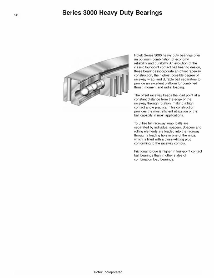
Rotek Incorporated
Series 3000 Heavy Duty Bearings
Rotek Series 3000 heavy duty bearings offeran optimum combination of economy, reliability and durability. An evolution of theclassic four-point contact ball bearing design,these bearings incorporate an offset racewayconstruction, the highest possible degree ofraceway wrap, and durable ball separators toprovide an excellent platform for combinedthrust, moment and radial loading.
The offset raceway keeps the load point at aconstant distance from the edge of the raceway through rotation, making a high contact angle practical. This construction provides the most efficient utilization of theball capacity in most applications.
To utilize full raceway wrap, balls are separated by individual spacers. Spacers androlling elements are loaded into the racewaythrough a loading hole in one of the rings,which is filled with a closely-fitting plug conforming to the raceway contour.
Frictional torque is higher in four-point contactball bearings than in other styles of combination load bearings.
50

51
Rotek Incorporated
Available in Many Models
Here is a summary of the range of specifica-tions that can be accommodated in Series3000 models:
Raceway Diameters:Standard models from 12” to 180”Special order bearings up to 360”
Maximum Raceway Velocity:700 feet per minute
Maximum Loads:(Standard models)
Thrust loads to 6,500,000 poundsMoment loads to 21,000,000 foot-poundsRadial loads to 1,200,000 pounds
� Contact Rotek for load information on special order models.
Operating Temperatures:Standard models to1750F Special models to 3750F
Tolerances:Available in standard or precision grades
Ideal for a Variety Of Heavy Duty Applications
Series 3000 bearings are ideal for a wide rangeof heavy duty bearing applications, including:• Stationary and mobile cranes• Excavators• Aerial Lifts• Industrial turntables• Turnstiles• Lift Truck Rotators• Mining equipment• Forestry equipment
Series 3000 Heavy Duty Bearings
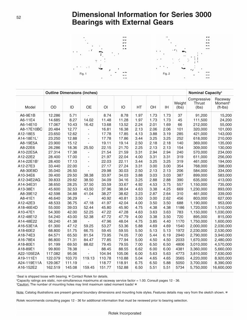
Rotek Incorporated
Dimensional Information for Series 3000Bearings with External Gears
52
Outline Dimensions (inches) Nominal Capacity2
Compressive RacewayWeight Thrust Moment3
Model OD ID OE OI IO HT OH IH (lbs) (lbs) (ft-lbs)
A6-9E1B 12.286 5.71 - 8.74 8.78 1.97 1.73 1.73 37 91,200 15,200A6-11E4 14.685 8.27 14.02 11.48 11.28 1.97 1.73 1.73 45 111,500 24,200A6-14E10 17.067 10.43 16.42 13.68 13.52 2.24 2.01 1.69 66 212,000 55,000A8-17E10BC 20.484 12.77 - 16.81 16.38 2.13 2.06 2.06 101 320,000 101,000
A12-18E5 23.650 12.62 - 17.78 17.85 4.13 3.88 3.19 285 421,000 143,000A14-18E1L1 23.250 12.88 - 17.78 17.86 3.44 3.25 3.25 252 618,000 210,000
A8-19E5A 23.900 15.12 - 19.11 19.14 2.50 2.18 2.18 140 369,000 135,000A8-22E6 26.286 18.36 25.50 22.15 21.70 2.25 2.13 2.13 154 309,000 130,000
A10-22E5A 27.314 17.38 - 21.54 21.59 3.31 2.94 2.94 240 570,000 234,000A12-22E2 28.400 17.00 - 21.97 22.04 4.00 3.31 3.31 319 611,000 256,000A14-22E1B1 28.400 17.13 - 22.03 22.11 3.44 3.25 3.25 319 461,000 194,000A12-27E3 33.440 22.00 - 27.17 27.24 3.31 3.00 3.00 354 768,000 398,000
A8-30E8D 35.040 26.50 - 29.98 30.03 2.50 2.13 2.13 206 584,000 334,000A10-34E6 39.400 29.50 38.38 33.97 34.03 3.88 3.03 3.03 387 899,000 583,000A12-34E2AG 39.833 29.62 38.50 34.09 34.16 3.25 2.88 2.88 390 635,000 413,000A14-34E31 38.650 28.25 37.50 33.59 33.67 4.92 4.53 3.75 557 1,150,000 735,000A13-38E1 45.600 32.53 43.50 37.96 38.04 4.63 3.38 4.25 669 1,230,000 893,000
A8-39E12 42.598 34.88 41.04 38.27 38.62 3.23 2.87 2.64 310 461,000 339,000A8-41E1 46.640 36.29 - 40.92 40.81 3.50 3.00 2.62 456 803,000 627,000
A12-42E3 48.533 36.75 47.18 41.97 42.04 4.00 3.50 3.50 688 1,190,000 953,000A18-46E4D 55.000 39.03 52.44 45.80 45.90 4.75 4.38 4.38 1186 1,720,000 1,510,000A10-47E1 54.300 42.00 52.25 47.22 47.28 4.63 3.63 3.63 783 1,150,000 1,030,000A12-48E12 54.240 43.00 52.38 47.72 47.79 4.00 3.38 3.50 720 895,000 815,000A14-48E22 56.240 41.38 - 47.96 48.04 4.75 3.85 4.40 1170 1,750,000 1,600,000A16-53E1A 61.300 47.12 59.25 53.27 53.36 5.88 4.69 4.69 1540 2,000,000 2,030,000A18-60E2 68.800 51.75 66.75 59.45 59.55 5.50 5.13 5.13 1972 2,230,000 2,530,000A18-74E3 84.571 65.50 81.54 73.95 74.05 7.00 5.44 6.19 2940 2,790,000 3,940,000A16-78E4 86.800 71.31 84.47 77.85 77.94 5.00 4.50 4.50 2033 1,670,000 2,480,000A18-80E1 91.199 69.50 88.62 79.45 79.55 7.00 6.50 6.50 4806 3,010,000 4,570,000A18-89E1 99.800 78.38 - 88.45 88.55 6.62 6.00 6.00 4381 3,360,000 5,660,000A22-105E2A 117.082 95.06 - 104.94 105.06 6.00 5.63 5.63 4773 3,810,000 7,630,000A19-111E1 122.079 103.70 119.13 110.78 110.88 5.04 4.65 4.65 3565 4,220,000 8,920,000A24-119E11A 129.067 111.19 - 118.77 118.91 6.75 6.50 5.88 5050 3,700,000 8,390,000A16-152E2 162.519 145.08 159.45 151.77 152.88 6.50 5.51 5.51 5734 5,750,000 16,600,000
1Seal is shipped loose with bearing. � Contact Rotek for details.2Capacity ratings are static, non-simultaneous maximums at raceway service factor = 1.00. Consult pages 12 - 36.3Caution: The number of mounting holes may limit maximum rated moment loads! �
Note: Catalog illustrations are present general boundary dimensions and mounting hole styles. Features details may vary from the sketch shown. �
Rotek recommends consulting pages 12 - 36 for additional information that must be reviewed prior to bearing selection.
Fig. 1 Fig. 2

53
Rotek Incorporated
Mounting Holes Gear Data
No. No. Tangentialof of Hole No. Gear
OBC IBC Figure of CapacityModel OBC OU Holes IBC IU Holes Style PD DP Teeth Tooth Form F (lbs)
A6-9E1B 10.630 5/8-11 16 6.890 5/8-11 16-1 2 12.000 5 60 20d, 5/7 Fellows 1.73 6200A6-11E4 13.189 5/8-11 16 9.449 5/8-11 20 2 14.400 5 72 20d, 5/7 Fellows 1.50 6000A6-14E10 15.354 5/8-11 18 11.614 5/8-11 24 2 16.800 5 84 20d, 5/7 Fellows 1.73 6800A8-17E10BC 18.874 5/8-11 20 14.374 5/8-11 20 2 20.200 5 101 20d, 5/7 Fellow 2.06 7700
A12-18E5 21.250 3/4-10 18 14.375 .94 24-1 4 23.250 4 93 20d, Stub 3.88 17100A14-18E1L 21.250 3/4-16 18 14.375 3/4-16 24-1 2 23.250 4 93 20d, Stub 3.25 14300A8-19E5A 21.500 3/4-101 20 16.625 .81 24-1 4 23.500 4 94 20d, Stub 2.18 10200A8-22E6 24.500 5/8-11 18 19.500 5/8-11 18 2 26.000 5 130 20d, 5/7 Fellows 2.00 7600
A10-22E5A 24.375 3/4-101 30 18.750 3/4-101 30-1 2 26.857 3.5 94 20d, Stub 2.94 148005
A12-22E2 25.378 7/8-91 24 18.618 .94 30-2 4 28.000 4 112 20d, 4/5 Fellow 3.31 14800A14-22E1B 25.380 .782 18 18.630 .782 24-1 1 28.000 4 112 20d, Stub 3.25 14500A12-27E3 30.250 3/4-10 28 23.875 .81 28 4 32.800 2.5 82 20d, Full Depth4 3.00 223005
A8-30E8D 32.250 .69 24 27.750 .69 28 1 34.400 2.5 86 20d, Stub 2.13 163005
A10-34E6 36.750 .81 36 31.250 .81 40-1 1 39.000 4 156 20d, 4/5 Fellows 2.75 12500A12-34E2AG 37.125 3/4-10 30 31.125 3/4-10 36 2 39.333 3 118 20d, 3/4 Fellows 2.50 15300A14-34E31 35.750 1-8 24 30.000 1.13 30-1 4 38.250 4 153 20d, 4/5 Fellow 3.27 15700A13-38E1 41.500 1.06 28 34.500 1.06 353 1 44.800 2.5 112 20d, Full Depth 2.88 18100
A8-39E12 39.961 M16x2 30 36.299 M16x21 30 2 41.260 3.175 131 20d, 8 Module4 2.87 144005
A8-41E1 43.500 .94 36 37.875 .94 36 1 46.000 2.5 115 20d, Stub 3.00 24000A12-42E3 45.250 1.00-8 36 38.750 1-8 42-1 2 48.000 3 144 20d, Stub 2.75 17600A18-46E4D 50.250 1.31 27 41.375 1.31 36-1 1 54.000 2 108 20d, Full Depth 4.00 31400A10-47E1 50.375 1.06 30 44.125 1.06 36 1 53.500 2 107 20d, Stub 3.00 26700A12-48E12 50.790 .94 36 44.690 .94 36 1 53.600 2.5 134 20d, Stub 3.25 23400A14-48E22 52.000 1.25-7 36 44.000 1.25-7 36 2 55.600 2.5 139 20d, Stub 3.85 27800A16-53E1A 57.375 1.06 40 49.250 1.06 45-1 1 60.500 2 121 20d, Stub 4.00 35800A18-60E2 64.250 1.25-7 54 54.500 1.25-7 54-1 2 68.000 2 136 20d, Stub 3.75 35800A18-74E3 78.625 1.38 60 68.750 1.38 523 1 83.429 1.75 146 25d, Full Depth 4.38 49100A16-78E4 82.125 1.31 48 73.688 1.31 48 1 86.000 2 172 20d, Stub 4.00 36500A18-80E1 85.500 1.50-6 48 73.000 1.50-6 52-1 2 90.286 1.75 158 20d, Stub 5.00 55000A18-89E1 94.250 1.50-61 60 82.500 1.50-61 60 2 99.000 2 198 20d, Stub 6.00 58300A22-105E2A 110.500 1.50-61 60 99.500 1.50-61 60-1 2 116.000 1.5 174 20d, Stub 5.63 72600A19-111E1 115.354 1.30 56 106.299 1.30 56 1 120.315 1.5875 191 20d, 16 Module4 4.53 462005
A24-119E11A 124.250 1.34 44 113.688 1.34 44 1 128.000 1.5 192 20d, Stub 6.50 84100A16-152E2 155.709 1.09 60 147.244 1.09 60 1 160.630 1.5875 255 20d, 16 Module4 4.53 46700
1Counter drilled for extra bolt stretch length � Contact Rotek for details.2Counter bored for socket head cap screws. � 3Mounting holes unequally spaced. � 4Corrected gear tooth profile. � 5Gear teeth induction hardened for wear resistance. �
Note: The catalog listing is only a small representationof the models available. Numerous larger, smaller andintermediate sized models are available that are not cataloged here. � Call your local Rotek Sales Engineer or the Rotek Application Engineering Department at800/221-8043 for information on non-cataloged models.
Fig. 3 Fig. 4
Dimensional Information for Series 3000Bearings with External Gears

Rotek Incorporated
Dimensional Information for Series 3000 Bearings with Internal Gears
54
Outline Dimensions (inches) Nominal Capacity2
Compressive RacewayWeight Thrust Moment3
Model OD ID IE OI IO HT OH IH (lbs) (lbs) (ft-lbs)
A8-17N4D 20.48 12.748 - 16.81 16.40 2.13 2.06 2.06 101 269,000 85,000A8-22N2A 25.75 16.850 - 22.03 22.06 2.75 2.38 2.38 184 309,000 130,000A8-25N21 28.75 21.350 22.38 24.99 25.02 3.50 2.88 3.38 228 350,000 167,000A9-25N3 28.75 19.543 20.75 24.72 24.78 3.38 2.63 3.00 242 529,000 250,000
A10-32N1A 36.75 26.400 - 31.97 32.03 3.86 3.00 3.50 405 775,000 473,000A14-33N1 38.59 24.960 26.50 32.46 32.38 4.38 3.50 4.00 557 1,170,000 723,000A10-35N1L 39.00 30.966 32.12 35.31 35.34 4.50 3.38 3.56 375 749,000 505,000A12-35N5 39.47 30.400 31.88 35.28 35.35 5.00 4.00 4.00 486 1,140,000 770,000
A7-38N1 41.75 33.110 34.59 37.87 37.91 2.17 1.89 1.89 232 490,000 354,000A10-43N28D 46.25 37.680 39.80 42.80 42.86 4.25 3.38 3.75 448 739,000 603,000A13-46N1A 51.13 39.760 - 45.81 45.88 4.19 3.62 3.81 722 1,480,000 1,300,000A12-47N3E 52.75 41.760 43.50 47.40 47.47 4.78 3.88 4.13 783 1,360,000 1,230,000A14-47N5A 52.00 41.280 42.97 46.71 46.79 5.06 3.62 4.69 770 1,680,000 1,500,000
A9-54N2 58.62 47.831 50.10 54.10 54.18 4.72 3.54 4.09 925 1,360,000 1,400,000A14-54N10C 60.00 46.700 48.62 54.22 54.30 5.50 4.50 4.50 1150 1,960,000 2,030,000A16-56N5 61.62 46.884 - 55.70 55.79 5.25 4.50 4.25 1295 2,100,000 2,230,000A16-59N2 66.22 49.700 52.27 59.21 59.30 4.25 3.88 3.88 1400 2,230,000 2,520,000A20-72N5A 79.94 61.600 64.25 71.95 72.06 5.12 4.75 4.75 2159 2,680,000 3,680,000A18-80N1 89.00 70.267 - 80.20 80.30 4.88 4.50 4.50 2425 3,040,000 4,660,000A16-95N6 100.25 88.960 - 95.27 95.36 5.00 4.50 4.50 1825 1,440,000 2,630,000A20-95N4 103.00 84.700 86.75 94.95 95.06 7.25 6.88 6.88 4400 3,540,000 6,410,000A24-107N1 117.00 93.600 96.13 106.43 106.57 6.00 5.62 5.62 5437 3,330,000 6,770,000A22-129N1 137.75 116.933 - 128.56 128.69 6.25 5.88 5.88 5601 6,510,000 16,000,000A22-166N1 176.38 153.600 157.00 166.14 165.86 9.50 9.00 9.00 13061 3,860,000 12,200,000
1Seal on one side only. � Contact Rotek for details.2Capacity ratings are static, non-simultaneous maximums at raceway service factor = 1.00. Consult pages 12 - 36.3Caution: The number of mounting holes may limit maximum rated moment loads! � Contact Rotek for details.
Note: Catalog illustrations represent general boundary dimensions and mounting hole styles. Features details may vary from the sketch shown.� Contact Rotek for details.
Rotek recommends consulting pages 12 - 36 for additional information that must be reviewed prior to bearing selection.
Fig. 1 Fig. 2
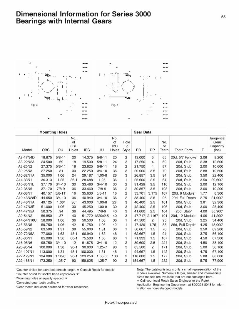
55
Rotek Incorporated
Mounting Holes Gear Data
No. No. Tangentialof of Hole No. Gear
OBC IBC Fig. of CapacityModel OBC OU Holes IBC IU Holes Style PD DP Teeth Tooth Form F (lbs)
A8-17N4D 18.875 5/8-11 20 14.375 5/8-11 20 2 13.000 5 65 20d, 5/7 Fellows 2.06 9,200A8-22N2A 24.500 .69 18 19.500 5/8-11 24 3 17.250 4 69 20d, Stub 2.38 12,600A8-25N2 27.375 5/8-11 18 23.625 5/8-11 18 2 21.750 4 87 20d, Stub 2.00 10,600A9-25N3 27.250 .81 30 22.250 3/4-10 36 3 20.000 3.5 70 20d, Stub 2.88 19,500
A10-32N1A 35.000 1.06 24 29.187 1.00-8 26 3 26.857 3.5 94 20d, Stub 3.50 22,400A14-33N1 36.313 1.25 36-1 28.688 1.25 36 1 25.600 2.5 64 20d, Stub 3.50 29,6005
A10-35N1L 37.170 3/4-10 30 33.460 3/4-10 30 2 31.429 3.5 110 20d, Stub 2.00 12,100A12-35N5 37.170 7/8-9 36 33.460 7/8-9 36 2 30.857 3.5 108 20d, Stub 3.00 19,200A7-38N1 40.157 5/8-111 16 35.630 5/8-111 16 2 33.701 3.175 107 20d, 8 Module4 1.77 8,300
A10-43N28D 44.650 3/4-10 36 40.940 3/4-10 36 2 38.400 2.5 96 20d, Full Depth 2.75 21,9005
A13-46N1A 49.125 1.062 303 43.000 1.00-8 223 3 40.400 2.5 101 20d, Stub 3.81 32,300A12-47N3E 51.000 1.06 30 45.250 1.00-8 30 3 42.400 2.5 106 20d, Stub 3.00 25,400A14-47N5A 50.375 .94 36 44.495 7/8-9 40 3 41.600 2.5 104 20d, Stub4 4.00 35,9005
A9-54N2 56.850 .87 40 51.772 M20x2.5 40 3 47.717 2.1167 101 20d, 12 Module4 4.06 41,2005
A14-54N10C 58.000 1.06 36 50.500 1.06 36 1 47.500 2 95 20d, Stub 3.25 34,400A16-56N5 59.750 1.06 42 51.750 1.06 42 1 47.429 1.75 83 25d, Full Depth4 4.25 48,0005
A16-59N2 63.500 1.31 38 55.000 1.31 36 1 50.667 1.5 76 20d, Stub 3.50 69,200A20-72N5A 77.060 1.63 48-1 66.940 1.63 48 1 62.667 1.5 94 20d, Stub 3.75 56,100A18-80N1 85.000 1.56 60-1 75.500 1.56 60 1 71.333 1.5 107 20d, Stub 4.50 67,300A16-95N6 98.750 3/4-10 12 91.875 3/4-10 12 2 89.600 2.5 224 20d, Stub 4.50 38,100A20-95N4 100.000 1.38 90-1 90.000 1.25-7 90 3 85.500 2 171 20d, Stub 5.00 56,100A24-107N1 113.000 1.31 48-1 100.000 1.31 48 1 94.667 1.5 142 20d, Stub 4.75 67,100A22-129N1 134.000 1.50-61 90-1 123.250 1.50-61 100 2 118.000 1.5 177 20d, Stub 5.88 88,000A22-166N1 173.250 1.25-7 90 159.625 1.25-7 90 2 154.667 1.5 232 20d, Stub 5.75 77,900
1Counter drilled for extra bolt stretch length. � Consult Rotek for details.2Counter bored for socket head capscrews. �3Mounting holes unequally spaced. �4Corrected gear tooth profile. �5Gear theeth induction hardened for wear resistance.
Note: The catalog listing is only a small representation of themodels available. Numerous larger, smaller and intermediatesized models are available that are not cataloged here.� Call your local Rotek Sales Engineer or the RotekApplication Engineering Department at 800/221-8043 for infor-mation on non-cataloged models.
Fig. 3 Fig. 4
Dimensional Information for Series 3000 Bearings with Internal Gears

Rotek Incorporated
Dimensional Information for Series 3000 Gearless Bearings
56
Outline Dimensions (inches) Nominal Capacity1
Compressive RacewayWeight Thrust Moment2
Model OD ID OI IO HT OH IH (lbs) (lbs) (ft-lbs)
A6-9P4 11.81 5.71 8.86 8.70 1.81 1.61 1.61 32 91,200 15,300A6-11P5 14.68 8.26 11.64 11.17 1.57 1.50 1.50 43 173,000 37,500A6-14P3D 16.54 10.43 13.46 13.50 1.97 1.73 1.73 56 80,000 20,600A8-17P1DU 20.48 12.74 16.81 16.38 2.13 2.06 2.06 101 320,000 101,000
A14-19P4 24.13 13.63 18.84 18.92 3.81 3.44 3.44 264 550,000 198,000A8-22P11 26.00 18.00 21.98 22.02 2.75 2.38 2.38 170 309,000 130,000
A13-22P4 27.50 16.63 21.96 22.04 3.50 3.13 3.13 275 697,000 292,000A4-23P2A 26.00 20.00 22.99 23.01 1.82 1.53 1.53 83 109,000 47,800A9-24P2 27.97 19.77 23.85 23.90 2.88 2.50 2.50 188 426,000 194,000
A14-24P1A 28.75 19.12 23.96 24.04 3.62 3.25 3.25 294 499,000 228,000A14-25P1 31.83 18.75 25.08 25.17 4.38 4.00 3.50 475 898,000 430,000A14-31P3 35.75 26.00 31.02 31.10 3.81 3.44 3.44 406 1,100,000 653,000A12-32P2 36.25 27.13 31.47 31.54 3.25 2.88 2.88 316 893,000 536,000A12-34P2B 39.80 29.65 34.09 34.16 3.25 2.88 2.88 426 635,000 413,000A10-35P1A 39.00 32.12 35.31 35.34 4.50 3.38 3.56 349 604,000 406,000A14-43P1 48.25 38.13 43.16 43.24 3.81 3.44 3.44 605 1,540,000 1,270,000A12-47P2 52.75 41.76 47.40 47.47 4.78 3.88 4.13 824 1,360,000 1,230,000A14-49P1A 53.62 43.38 48.46 48.54 4.19 3.81 3.81 703 1,010,000 935,000A14-56P1E 61.64 49.50 55.77 55.85 5.34 4.52 4.09 1005 1,160,000 1,240,000A18-60P1B 66.63 54.00 60.26 60.36 5.63 5.13 5.00 1593 1,360,000 1,570,000A16-67P2 73.88 60.25 66.96 67.05 4.50 4.00 4.00 1442 2,530,000 3,230,000A16-79P1A 84.75 72.75 78.71 78.79 4.25 3.88 3.88 1510 2,980,000 4,470,000A16-86P1 91.00 80.00 85.46 85.55 6.00 4.75 4.75 1822 1,500,000 2,430,000A14-89P1 49.62 84.50 89.21 90.04 4.63 4.25 3.62 1476 1,270,000 2,170,000A18-89P1 96.50 82.28 88.95 89.05 6.30 4.76 5.91 2623 2,030,000 3,440,000A22-98P1 105.75 90.17 97.98 98.11 5.76 5.38 5.38 3204 2,770,000 5,180,000A10-110P2D 114.25 105.75 109.97 110.03 3.00 2.62 2.62 981 1,910,000 4,000,000A12-125P1 129.92 119.33 124.73 124.77 5.50 4.00 4.50 2400 2,350,000 5,600,00A19-150P1 157.52 141.69 149.55 149.66 5.04 4.64 4.64 4295 5,720,000 16,300,000
1Capacity ratings are static, non-simultaneous maximums at raceway service factor = 1.00. Consult pages 12 - 36.2Caution: The number of mounting holes may limit maximum rated moment loads! � Contact Rotek for details.
Note: Catalog illustrations represent general boundary dimensions and mounting hole styles. Features details may vary from the sketch shown. �
Rotek recommends consulting pages 12 - 36 for additional information that must be reviewed prior to bearing selection.
Fig. 1 Fig. 2

57
Rotek Incorporated
Mounting Holes
No. of No. of HoleOBC IBC Fig.
Model OBC OU Holes IBC IU Holes Style
A6-9P4 10.630 .66 10 6.890 .66 10 1A6-11P5 13.189 1/2-13 16 9.449 1/2-13 20-1 2A6-14P3D 15.354 5/8-11 18 11.614 .66 24-1 4A8-17P1DU 18.875 5/8-11 20 14.375 5/8-11 20 2
A14-19P4 22.438 .97 24-1 15.312 7/8-91 24 3A8-22P11 24.500 .78 20 19.500 3/4-10 20 3
A13-22P4 25.375 1.06 24 18.625 1.06 24 1A4-23P2A 25.000 .53 12 21.000 1/2-13 12 2A9-24P2 26.625 3/4-11 30 21.125 3/4-11 30 2
A14-24P1A 27.375 .812 30 20.625 .812 30-1 1A14-25P1 29.000 1.31 27 21.250 1.312 23 1A14-31P3 34.125 3/4-10 30-1 27.625 .782 30 4A12-32P2 34.500 .81 40-1 28.500 3/4-10 40 3A12-34P2A 37.000 .692 24 30.750 5/8-11 24 3A10-35P1A 37.170 3/4-11 30 33.460 3/4-11 30 2A14-43P1 46.625 .81 36 39.750 .81 36 1A12-47P2 51.000 1.06 30 45.250 1.00-8 30 3A14-49P1A 52.000 .94 50-1 45.000 .94 60 1A14-56P1E 59.625 1.06 36 52.000 1.00-8 36 4A18-60P1B 64.625 1.06 40 56.000 1.06 40 1A16-67P2 71.250 1.31 60-1 62.750 1.25-7 60 3A16-79P1A 82.750 1.00-81 32 74.750 1.00-81 32 2A16-86P1 89.000 3/4-10 48 83.000 3/4-10 48 2A14-89P1 92.500 3/4-10 20 86.000 .81 20 4A18-89P1 93.504 1.30 48 84.449 1.30 48 1A22-98P1 103.000 1.44 60-1 92.913 1.44 60 1A10-110P2D 112.750 5/8-11 48 107.250 .721 48 4A12-125P1 128.125 .94 36 121.250 .94 36 1A19-150P1 154.488 1.50-6 72 144.750 1.63 72 4
1Counter drilled for extra bolt stretch length. � Contact Rotek for details.2Counter bored for socket head capscrews.
Note: The catalog listing is only a small representation of the models available. Numerous larger, smaller and intermediate sized models are available that are not cataloged here. � Call you local Rotek Sales Engineer or the Rotek Application Engineering Department at 800/221-8043 forinformation on non-cataloged models.
Fig. 3 Fig. 4
Dimensional Information for Series 3000 Gearless Bearings

Series 4000 Two Row Ball Bearings
Series 4000 two-row ball bearings aredesigned for applications where mount-ing structures need to be relatively lightin weight, for example, as in climbingcranes, tower cranes, and stackercranes.
Series 4000 bearings are built with twosets of raceways and ball bearings. Thisdesign provides greater internal clear-ance and lower frictional torque, fea-tures that can compensate for thereduced accuracy and rigidity that canaccompany a lighter mounting structure.
Available in Many Models
Here is a summary of the range ofspecifications that can be satisfied withRotek Series 4000 bearings:
Bearing diameters:Domestic models from 12” to 180” O.D.
Maximum Raceway Velocity:700 feet per minute
Maximum Loads:(Standard Models)
Thrust loads to 8,700,000 poundsMoment loads to 24,000,000foot-poundsRadial loads to 860,000 pounds
� Contact Rotek for load informationon special order models.
Tolerances:Available in standard grades
Gearing:Internal or external gearing;or gearless
Note: These bearings are not typicallyinventoried. Contact Rotek for currentlead times and requirement involvingimmediate availability.
Ideal for Less Accurate or RigidMounting Structures
Series 4000 bearings have been usedextensively in equipment that requirerelatively light mounting structures.Typical applications incude:
• Climbing cranes• Stackers/reclaimers• Large industrial turntables• Turnstiles• Mining equipment• Tower Cranes
58
Rotek Incorporated
Capacity Curves
The raceway capacity charts can beused to select a Series 4000 model forspecific application loads.
To use the charts, first calculate the netthrust and moment loads for the application. Next, multiple these figuresby the appropriate recommended minimum service factor, (see page 19).Then plot the corrected thrust andmoment loads on the appropriate chart.From the point where the plot linesintersect, select the bearing whosecapacity is at, above, or to the right ofthe intersection point.
Bolt capacities may limit the racewaymoment capacities shown.

59
Rotek Incorporated
Series 4000 Dimensions and Capabilities
Outline Dimensions (inches)
Model OD ID OE OI IO HT OH
H7-30E1 33.90 26.73 32.80 30.50 31.38 3.23 3.28H7-38E1 42.50 35.27 41.00 38.90 39.84 3.23 2.28H8-58E2 62.60 53.70 61.00 58.30 59.45 4.06 3.35
Outline Dimensions (inches)
Model OD ID IE OI IO HT OH
H7-35N1 38.30 31.00 32.3 33.62 34.60 3.23 3.07H7-43N1 45.80 37.70 39.8 41.10 42.10 3.54 3.07
H7-43N3A 45.80 37.80 — 41.10 42.10 3.84 3.07H8-54N1 57.60 46.56 48.40 51.57 53.00 4.02 3.78
Gear Data Mounting Holes Nominal Capacity
Tooth No. Gear Max. allow. No. of No. of CompressiveForm of Hardness tang. tooth Holes Holes Thrust Moment Wt. Fig.
Model IH K PD DP 20˚ F Teeth (BHN) load (lbs) OBC OU OBC IBC IU IBC (lbs) (ft-lbs) (lbs) no.
H7-35N1 2.28 .95 31.430 3.5 STUB 1.97 110 180-210 5250 37.17 5/8-11 30 33.46 5/8-11 30 338,000 230,000 270 2H7-43N1 2.59 .95 38.400 2.5 F.D. 2.17 96 180-210 7100 44.65 5/8-11 36 40.94 5/8-11 36 412,000 333,000 350 2H7-43N3A 2.60 .94 38.400 2.5 STUB 2.60 96 250-300 13000 44.65 .71 36 40.94 5/8-11 36 412,000 333,000 355 4H8-54N1 3.04 .98 47.20 2.5 STUB 2.76 118 180-210 10330 56.10 .91 40 50.00 .91 40 683,000 588,000 760 3
Gear Data Mounting Holes Nominal Capacity
Tooth No. Gear Max. allow. No. of No. of CompressiveForm of Hardness tang. tooth Holes Holes Thrust Moment Wt. Fig.
Model IH K PD DP 20˚ F Teeth (BHN) load (lbs) OBC OU OBC IBC IU IBC (lbs) (ft-lbs) (lbs) no.
H7-30E1 3.07 .95 33.50 4 STUB 1.97 134 180-210 4650 31.50 5/8-11 24 27.80 5/8-11 24 273,000 160,000 230 1H7-38E1 3.07 .95 42.00 3.5 STUB 1.97 147 180-210 5400 39.96 5/8-11 30 36.30 5/8-11 30 373,000 272,000 290 1H8-58E2 3.94 .71 62.00 2.5 STUB 2.36 155 180-210 9100 59.53 3/4-10 40 55.12 3/4-10 40 670,000 633,800 750 1
Nominal capacity ratings are non-simultaneous maximums at raceway service factor = 1.00. Referto the capacity curves for combined loading.Catalog illustrations are approximate. Seals, boltspacing and other details may vary. Contact theRotek Application Engineering Department for
current drawings prior to doing significant layoutand design.
Rotek recommends consulting pages 12 - 36 foradditional information that must be reviewed priorto bearing selection.
Numerous larger, smaller and intermediate sizedstandard models are available that are not cataloged here. � Call your local Rotek SalesEngineer or the Rotek Application EngineeringDepartment at 800/221-8043 for information onnon-cataloged models.
External Gears
Internal Gears
Fig. 1 Fig. 2 Fig. 3 Fig. 4

Rotek Incorporated
Series 5000 Cross Roller Heavy Duty Bearings
The Rotek Series 5000 bearing is designed tosustain radial, thrust and moment loads whichmay occur individually or in combination.
To accomplish this universal load carryingcapability, the Series 5000 bearing is manufactured with V-groove raceways thatprovide two roller paths in each ring. Therollers have a length slightly less than thediameter and are positioned between therings in such a manner that adjacent rollersare at right angles to each other and contactopposing sets of raceways. By alternatingrollers in this manner, one-half of the rollerstransmit load in one direction and the otherhalf transmit load in the other direction. Therolling elements are normally separated byindividual spacers which occupy a minimumamount of space, permitting the use of nearlya full compliment of rollers.
The static thrust and moment capacity of across roller bearing is generally less than thatof a comparable size four-point contact ballbearing, but has considerably higher radialload capacity. The Series 5000 cross rollerbearing, however, offers the advantages ofgreater stiffness and a lower spring rate compared to a four-point contact ball bearing.These advantages make the cross rollerbearing preferable in situations where deflection under load must be minimized, asin some machine tool applications. Thegreater resistance to deflection offered by thecross roller bearing requires that it be
mounted to a mating surface that is properlyengineered to accommodate its greater stiffness. When properly mounted, the crossroller bearing has a higher theoretical dynamic capacity per unit size than the single-row ball bearing.
Available in Many Models
Here is a summary of the range or specifications that can be accomodated inSeries 5000 models:
Bearing Diameters:Domestic models from 12” to 180” O.D.
Maximum Raceway Velocity:700 feet per minute
Maximum Loads:(Standard Models)
Thrust loads to 4,600,000 poundsMoment loads to 16,000,000 foot-poundsRadial loads to 2,200,000 pounds
Tolerances:Available in standard or precision grades
� Contact Rotek for load information on special order models.
These bearings are not typically inventoried.Contact Rotek for current lead times andrequirements involving immediate availability.
Ideal for Demanding Applications
Series 5000 bearings have demonstratedexcellent performance in a variety of applica-tions where transmission of heavy loads withminimal deflection of the bearing is required:
• Machine tools• Radar antennas• Mining equipment• Lift truck rotators• Tunnel boring machines
60

61
Rotek Incorporated
Series 5000 Load Capacities of Selected Models
Capacity Curves
The raceway capacity charts at right canbe used to select a Series 5000 model forspecific application loads.
To use the charts, first calculate the netthrust and moment loads for the applica-tion. Next, multiply these figures by theappropriate recommended minimum service factor, (see page 19.) Then plotthe corrected thrust and moment loads onthe appropriate chart. From the pointwhere the plot lines intersect, select thebearing whose capacity is at, above, or tothe the right of the intersection point.
For models not shown on the charts, consult the dimensional tables (page 63)for maximum nominal thrust and momentcapacities. These models may be addedto the charts below by simply drawing aline from the appropriate point on thethrust axis to the appropriate point on themoment axis, using the values listed inthe dimensional tables. Bolt capacitiesmay limit the raceway moment capacities shown.

Rotek Incorporated
Series 5000 Dimensional Information
Outline Dimensions (inches)
Model OD ID OI IO HT OH IH PD
R8-30E3 35.150 26.06 30.157 30.000 2.874 2.520 2.520 34.750R8-35E3 40.533 30.87 34.961 34.803 2.874 2.520 2.520 40.000R8-39E3 43.867 34.57 38.661 38.504 2.874 2.520 2.520 43.333R8-42E3 48.240 38.39 42.480 42.323 2.874 2.520 2.520 47.600R8-44E3 50.240 39.69 44.173 44.016 2.874 2.520 2.520 49.600R8-46E3 52.640 42.05 46.535 46.378 2.874 2.520 2.520 52.000R8-49E3 65.040 44.80 49.291 49.134 2.874 2.520 2.520 54.000R8-52E3 58.800 47.56 52.047 51.890 2.874 2.520 2.520 58.000R9-55E3 62.300 49.84 55.197 55.139 3.150 2795 2.795 61.500R9-59E3 66.300 53.78 59.134 58.976 3.150 2.795 2.795 65.500R9-63E3 70.629 57.72 63.071 62.913 3.150 2.795 2.795 69.714R9-67E3 75.200 61.65 67.008 66.850 3.150 2.795 2.795 74.286R11-71E3 80.342 64.13 70.945 70.787 3.858 3.504 3.504 79.429R11-75E3 83.771 68.07 74.882 74.724 3.858 3.504 3.504 82.857R11-79E3 87.771 72.00 78.819 78.661 3.858 3.504 3.504 86.857
External Gears
Outline Dimensions (inches)
Model OD ID OI IO HT OH IH PD
R8-30N3 34.09 25.100 30.157 30.000 2.874 2.520 2.520 25.500R8-35N3 38.90 29.467 34.961 34.803 2.874 2.520 2.520 30.000R8-39N3 42.60 33.313 38.661 38.504 2.874 2.520 2.520 33.667R8-42N3 46.72 36.560 42.480 42.323 2.874 2.520 2.520 37.200R8-44N3 45.50 38.160 44.173 44.016 2.874 2.520 2.520 38.800R8-46N3 50.87 40.160 46.535 46.378 2.874 2.520 2.520 40.800R8-49N3 53.62 43.360 49.291 49.134 2.874 2.520 2.520 44.000R8-52N3 56.38 45.200 52.047 51.890 2.874 2.520 2.520 46.000R9-55N3 60.39 47.700 55.197 55.039 3.150 2.795 2.795 48.500R9-59N3 64.33 51.700 59.134 58.976 3.150 2.795 2.795 52.500R9-63N3 68.27 55.086 63.071 62.913 3.150 2.795 2.795 56.000R9-67N3 72.20 59.086 67.008 66.850 3.150 2.795 2.795 60.000R11-71N3 77.60 61.371 70.945 70.787 3.858 3.504 3.504 62.286R11-75N3 81.54 65.371 74.882 74.724 3.858 3.504 3.504 66.266R11-79N3 85.47 69.943 78.819 78.661 3.858 3.504 3.504 70.857
Internal Gears
62

Nominal Capacity ratings are non-simultane-ous raceway maximums (RWSF=1.00 for anyone load).
Nominal Moment Capacity ratings may belimited by bolts.
Load Capacity charts are valid for combinedAxial and Moment loads only; they should notbe used when radial loads exceed 10% of theaxial load.
Load Capacity Chart moment capacities maybe limited by bolt load capacities.
Nominal capacity ratings are non-simultane-ous maximums at raceway service factor =1.00. Refer to the capacity curves for com-bined loading. Catalog illustrations are approx-imate. Seals, bolt spacing and other detailsmay vary.
� Contact the Rotek Application Engineering Department for current drawings prior to doingsignificant layout and design.
Rotek recommends consulting pages 12 - 36for additional information that must bereviewed prior to bearing selection.
Numerous larger, smaller and intermediatesized standard models are available that arenot cataloged here. Call your local RotekSales Engineer or the Rotek ApplicationEngineering Department at 800/221-8043 forinformation on non-cataloged models.
Note: Many Gears are modified. Requestdrawing from Rotek.
63
Rotek Incorporated
Gear Data Mounting Holes Nominal Capacity
Tooth Gear Max. Allow. No. of No. of CompressiveForm Hardness No. of Tang. Tooth Holes Holes Thrust Moment Wt.
DP (20˚) (BHN) F Teeth Load (lbs) OBC OU OBC IBC IU IBC (lbs) (ft-lbs) (lbs)
4 Stub 250-300 2.520 139 11,309 32.625 .69 24 27.500 .69 24 373.200 228,700 2803 Stub 250-300 2.520 120 14,900 37.500 .69 30 32.250 .69 30 431,700 309,800 3393 Stub 250-300 2.520 130 15,000 41.125 .69 30 36.000 .69 30 476,600 369,500 363
2.5 Stub 250-300 2.520 119 17,800 45.000 .69 36 39.875 .69 36 526,100 459,100 4212.5 Stub 250-300 2.520 124 17,900 46.750 .81 36 41.375 .81 36 553,000 501,600 4602.5 Stub 250-300 2.520 130 18,000 49.125 .81 36 43.750 .81 36 580,000 552,400 4872.5 Stub 250-300 2.520 136 18,100 51.875 .81 40 46.500 .81 40 618,300 617,400 5112 Stub 250-300 2.520 116 22,200 54.625 .81 42 49.250 .81 42 656,500 685,900 5842 Stub 250-300 2.795 123 24,800 58.375 1.06 36 51.875 1.06 36 741,900 829,800 7762 Stub 250-300 2.795 131 24,900 62.250 1.06 40 55.875 1.06 40 794,300 946,300 857
1.75 Stub 250-300 2.795 122 28.300 66.250 1.06 40 59.750 1.06 40 836,300 1,099,000 9031.75 Stub 250-300 2.795 130 28,500 70.125 1.06 44 63.750 1.06 44 894,800 1,217,000 10031.75 Stub 250-300 3.504 139 36,000 75.000 1.31 36 66.750 1.31 36 1,207,300 1,733,300 15801.75 Stub 250-300 3.504 145 36,200 79.000 1.31 36 70.625 1.31 36 1,290,400 1,954,600 16641.75 Stub 250-300 3.504 152 36,300 82.875 1.31 40 74.625 1.31 40 1,348,900 2,109,400 1732
Gear Data Mounting Holes Nominal Capacity
Tooth Gear Max. Allow. No. of No. of CompressiveForm Hardness No. of Tang. Tooth Holes Holes Thrust Moment Wt.
DP (20˚) (BHN) F Teeth Load (lbs) OBC OU OBC IBC IU IBC (lbs) (ft-lbs) (lbs)
4 Stub 250-300 2.520 102 12,600 32.625 .69 24 27.500 .69 24 373,200 228,700 2733 Stub 250-300 2.520 90 16,600 37.500 .69 30 32.250 .69 30 431,700 309,800 3243 Stub 250-300 2.520 101 16,800 41.125 .69 30 36.000 .69 30 476,600 369,500 361
2.5 Stub 250-300 2.520 93 20,100 45.000 .69 36 39.875 .69 36 526,100 459,100 4162.5 Stub 250-300 2.520 97 20,200 46.750 .81 36 41.375 .81 36 553,000 501,600 4512.5 Stub 250-300 2.520 102 20,200 49.125 .81 36 43.750 .81 36 580,000 552,400 4782.5 Stub 250-300 2.520 110 20,400 51.875 .81 40 46.500 .81 40 618,300 617,400 5072 Stub 250-300 2.520 92 25,100 54.625 .81 42 49.250 .81 42 656,500 685,900 5662 Stub 250-300 2.795 97 28,100 58.375 1.06 36 51.875 1.06 36 741,900 829,800 7692 Stub 250-300 2.795 105 28,000 62.250 1.06 40 55.875 1.06 40 794,300 946,300 802
1.75 Stub 250-300 2.795 96 31,900 66.250 1.06 40 59.750 1.06 40 836,300 1,099,000 9101.75 Stub 250-300 2.795 105 32,000 70.125 1.06 44 63.750 1.06 44 894,800 1,217,000 9301.75 Stub 250-300 3.504 109 40,400 75.000 1.31 36 66.750 1.31 36 1,207,300 1,733,300 15561.75 Stub 250-300 3.504 116 40,600 79.000 1.31 36 70.625 1.31 36 1,290,400 1,954,600 16601.75 Stub 250-300 3.504 124 40,700 82.875 1.31 40 74.625 1.31 40 1,348,900 2,109,400 1693
Series 5000 Dimensional Information
Model
R8-30E3R8-35E3R8-39E3R8-42E3R8-44E3R8-46E3R8-49E3R8-52E3R9-55E3R9-59E3R9-63E3R9-67E3R11-71E3R11-75E3R11-79E3
Model
R8-30N3R8-35N3R8-39N3R8-42N3R8-44N3R8-46N3R8-49N3R8-52N3R9-55N3R9-59N3R9-63N3R9-67N3R11-71N3R11-75N3R11-79N3

Rotek Incorporated
64 Series 6000 High-Speed Radial Ball Bearings
Rotek Series 6000 bearings are single row,high-speed ball bearings capable of racewayvelocities of up to 3,000 feet per minute withproper lubrication
These bearings feature exceptionally durableradial cages and are capable of sustainedhigh-speed operation. Series 6000 bearingsare often selected based on dynamic capacity limitations which impose moresevere limits on loads than static capacity.
Available In Many Models
Here is a summary of the range of specifications that can be accommodatedwith Rotek Series 6000 bearings:
Bearing Diamters:Domestic models from 12” to 180” O.D.
Maximum Raceway Velocity:up to 3,000 feet per minute(Oil lubrication recommended over 1,000 fpm)
Maximum Loads:(Standard Models)
Thrust loads to 1,000,000 poundsMoment loads to 2,5000,000 foot-poundsRadial loads to 244,000 pounds
� Contact Rotek for loadinformation on special order models.
Tolerances:Available in standard or precision grades
Gearing:Gearless models most common
Ideal For High-Speed Applications
Series 6000 bearings have been used exten-sively in equipment that requires high-speedrotation capabilities. Typical applicationsinclude:
• Log-debarking machines• Coil windows• Payoff reels• High-speed capstans
Capacity Curves
The raceway capacity charts at right can beused to select a Series 6000 model for spe-cific application loads.
To use the charts, first calculate the netthrust and moment loads for the application.Next, multiple these figures by the appropri-ate recommended minimum service factor,(see page 19). Then plot the corrected thrustand moment loads on the appropriate chart.From the point where the plot lines intersect, select the bearing whosecapacity is at, above, or to the right of theintersection point.
Bolt capacities may limit the racewaymoment capacities shown.
� Contact Rotek for dynamic capacities.

Outline Dimensions (inches) Mounting Holes
StaticNo. Of No. Of Radial
Model Holes Holes Capacity WeightNo. OD ID OI IO OH IH K PH OBC OU OBC IBC IU IBC (lbs) (lbs)
W13-24P1 31.890 21.654 27.09 26.46 3.55 2.77 .39 .59 30.510 5/8 -11 12 23.23 5/8 -11 12 53,570 368W13-35P1 40.555 29.525 35.36 34.72 3.74 2.96 .39 .59 38.785 5/8 -11 16 — — — 66,960 510W13-38P1 43.310 32.280 38.11 37.48 3.74 2.96 .39 .59 41.540 5/8 -11 16 34.25 5/8 -11 16 80,350 564W13-43P2 48.429 37.399 43.23 42.60 3.74 2.96 .39 .59 46.659 5/8 -11 16 — — — 88,380 629W13-49P1 55.120 43.310 49.53 48.90 3.94 3.16 .39 .59 52.950 5/8 -11 24 45.47 5/8 -11 24 96,420 807W13-51P1D 57.085 45.275 51.50 50.86 3.94 3.16 .39 .59 54.915 5/8 -11 24 — — — 104,450 860W14-60P1 66.530 53.150 60.24 59.45 4.33 3.55 .39 .59 63.980 5/8 -10 24 56.10 3/4 -10 24 127,750 1270W14-71P1 78.740 63.780 71.65 70.87 4.72 3.94 .39 .59 75.390 5/8 -10 24 67.32 3/4 -10 24 166,080 1911W16-84P1 91.340 75.590 84.25 83.45 5.11 4.33 .39 .59 88.580 1 - 8 30 79.53 1 - 8 30 204,420 2504W17-108P1 116.930 99.210 108.74 107.80 5.51 4.33 .59 .59 113.190 1 - 8 30 103.54 1 - 8 30 244,240 3740
Rotek Incorporated
65Series 6000 Dimensions and Capacities
Nominal capacity ratings are non-simultaneous maximums at raceway service factor = 1.00. Refer to thecapacity curves for combined loading. Catalog illustrationsare approximate. Seals, bolt spacing and other detailsmay vary. Contact the Rotek Application EngineeringDepartment for current drawings prior to doing significantlayout and design.
Rotek recommends consulting pages 12 - 36 for additional information that must be reviewed prior to bearing selection.
Numerous larger, smaller and intermediate sized standardmodels are available that are not cataloged here. Callyour local Rotek Sales Engineer or the Rotek ApplicationEngineering Department at 800/221-8043 for informationon non-cataloged models.

Rotek Incorporated
Series 7100 and 8000 Single Row VerticalThrust Bearings
Series 7100 and Series 8000 bearings aresingle row ball bearings designed for applica-tions where the center of force remains with-in the bearing diameter under normal operat-ing conditions. Thrust is transmitted at a 90˚contact angle, making the most efficient useof the bearing capacity.
Series 7100 bearings include lift-off protec-tion to hold the assembly together underoccasional uplifting loads.
Series 8000 bearings are furnished as rings,raceways, balls and separators only. Nomounting holes or gearing are available onthis style bearing. They offer the lowest costper unit diameter for heavy pure thrust loads.
Available In Many Models
Here is a summary of the range of specifica-tions that can be accommodated with RotekSeries 7100 and Series 8000 bearings:
Bearing Diameters:Domestic models from 12” to 180” O.D.
Maximum Raceway Velocity:700 feet per minute
Maximum Loads:Thrust loads to 1,290,000 pounds
Series 7100 and Series 8000 bearings arenot intended or recommended for moment orradial loading.
Tolerances:Available in standard grades only.
Gearing:Series 7100: Internal and external gearing,or gearless
Series 8000: Available in gearless modelsonly
Ideal For Heavy Pure Thrust Loads
Series 7100 and Series 8000 bearings havebeen used extensively in applications wherethe center of force remains within the bearingdiameter under normal operating conditions.Typical applications include:
• Large turntables• Sewage and water treatment equipment• Clarifiers• Thickeners• Rotary distributors
Series 7100
Series 8000
66

Rotek Incorporated
67Series 7100 Dimensions and Capacities
Outline Dimensions (inches)
ModelNo. OD ID OI IO HT OH IH
S8-50E1 54,867 46.50 49.56 50.44 2.88 2.62 2.25S8-56E1 60,867 52.50 55.56 56.44 2.88 2.62 2.25S10-63E1 67.867 58.38 61.95 63.05 3.19 2.88 2.56S12-70E1 76.240 65.38 69.34 70.66 3.44 3.12 2.81S14-80E1 86.640 74.62 79.11 80.64 4.38 4.00 3.38S14-90E1 96.640 84.62 89.11 90.64 4.38 4.00 3.38S16-100E1 107.800 94.00 99.12 100.88 4.62 4.25 3.62S16-112E1 119.800 106.00 111.12 112.88 4.62 4.25 3.62S20-125E1 134.057 117.88 123.90 126.10 5.44 5.00 4.44S22-140E1 149.733 132.75 138.79 141.21 5.75 5.25 4.75S24-158E1 168.480 149.50 156.48 158.82 6.00 5.50 5.00S24-178E1 189.280 168.00 176.18 178.82 6.00 5.50 5.00
Gear Data Mounting Holes
Tooth Gear No. Max. Allow. No. of No. of ThrustModel Form Hardness Of Tang. Tooth Holes Holes Wt. Capacity
No. PD DP (20˚) (BHN) Teeth Load (lbs) OBC OU OBC IBC IU IBC (lbs) (lbs)
S8-50E1 54.333 3 STUB 250-300 163 15,820 52,5000 .56 24 47.500 .56 24 417 235,000S8-56E1 60.333 3 STUB 250-300 181 15.960 58.500 .56 24 53.500 .56 24 469 262,000S10-63E1 67.333 3 STUB 250-300 202 17,640 65.500 .69 24 59.500 .69 24 629 321,000S12-70E1 75.600 2.5 STUB 250-300 189 22,820 73.250 .81 24 66.750 .81 24 906 387,000S14-80E1 86.000 2.5 STUB 250-300 215 29,400 83.500 .94 24 76.250 .94 24 1440 469,000S14-90E1 96.000 2.5 STUB 250-300 240 29,540 93.500 .94 24 86.250 .94 24 1624 529,000S16-100E1 107.000 2 STUB 250-300 214 39,060 104.000 1.06 24 96.000 1.06 24 2193 620,000S16-112E1 119.000 2 STUB 250-300 238 39,200 116.000 1.06 24 108.000 1.06 24 2444 693,000S20-125E1 133.143 1.75 STUB 250-300 233 52,780 129.500 1.19 24 120.000 1.19 24 3805 847,000S22-140E1 148.667 1.50 STUB 250-300 223 65,900 145.000 1.19 24 135.000 1.19 24 4769 989,000S24-158E1 167.200 1.25 STUB 250-300 209 80,780 163.000 1.19 24 152.000 1.19 24 6195 1,150,000S24-178E1 188.000 1.25 STUB 250-300 235 81,340 183.000 1.19 24 171.000 1.19 24 7894 1,290,000
Nominal capacity ratings are non-simultaneous maximumsat raceway service factor = 1.00. Refer to the capacitycurves for combined loading. Catalog illustrations areapproximate. Seals, bolt spacing and other details mayvary. Contact the Rotek Application EngineeringDepartment for current drawings prior to doing significantlayout and design.
Rotek recommends consulting pages 12 - 36 for additionalinformation that must be reviewed prior to bearing selection.
Numerous larger, smaller and intermediate sized standardmodels are available that are not cataloged here. Call yourlocal Rotek Sales Engineer or the Rotek ApplicationEngineering Department at 800/221-8043 for informationon non-cataloged models.

Rotek Incorporated
Series 10,000 Heavy Duty Bearings
Rotek Series 10,000 heavy duty bearingsoffer more load capacity per unit size thanany other Rotek design. Series 10,000 bear-ings are constructed with three independentrows of rollers. Rollers are separated byeither steel cages or plastic spacers, depend-ing on application requirements.
Since all loading is transmitted directly toraceway surfaces that are perpendicular tothe load direction, the capacity of each rollingelement is utilized in the most efficient man-ner possible.
The perpendicular arrangement of the rollingelements also minimizes the amount of axialdeflection that occurs between the bearingrings when under load, making the Series10,000 inherently the stiffest bearing avail-able from Rotek. In addition, frictional torqueis lower than other styles of Rotek bearingsunder most load conditions.
Because of their high-load carrying capability,Series 10,000 bearings must be mounted ona companion structure which is sufficientlyuniform in stiffness to properly distribute theloading around the bearing. (See page 29 forinformation on companion structure require-ments.) Special consideration must also be
given to the number of mounting holes andbolts that will be required to safely transmitthe maximum rated moment load. In somemodels, mounting holes in addition to stan-dard specifications may be required.
Available in Many Models
Here is a summary of the range of specifica-tions that can be accommodated in Series10,000 models:
Raceway Diameters:Standard models from 12” to 180”Special order bearings up to 360”
Maximum Raceway Velocity:700 feet per minute
Maximum Loads:(Standard models)
Thrust loads to 23,000,000 poundsMoment loads to 61,000,000 foot-poundsRadial loads to 2,500,000 pounds
� Contact Rotek for load information on special order models.
Tolerances:Available in standard or precision grades
Ideal for Demanding Applications
Series 10,000 bearings have demonstratedexcellent durability in a variety of applicationswhere extremely heavy loads are involved.Typical applications include:
• Heavy Duty Cranes, including off-shore, ship-board, dockside and crawler crane applications• Excavators• Stackers/Reclaimers• Tunnel-boring Machines• Precision radar antenna pedestals• Ladle Turrets• Mooring Buoys
68
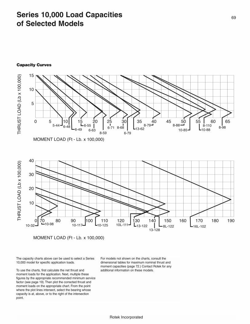
Rotek Incorporated
Series 10,000 Load Capacities of Selected Models
The capacity charts above can be used to select a Series10,000 model for specific application loads.
To use the charts, first calculate the net thrust andmoment loads for the application. Next, multiple these figures by the appropriate recommended minimum servicefactor (see page 19). Then plot the corrected thrust andmoment loads on the appropriate chart. From the pointwhere the plot lines intersect, select the bearing whosecapacity is at, above, or to the right of the intersectionpoint.
For models not shown on the charts, consult the dimensional tables for maximum nominal thrust andmoment capacities (page 72.) Contact Rotek for any additional information on these models.
Capacity Curves
69

Series 10,000 Dimensional Information
External Gears Outline Dimensions (inches) Gear Data
Tooth GearForm Hardness
Model Number HT OH K IH OD OI IO ID PD DP (20°) (BHN)
3R6-48E3B 5.00 4.50 .50 4.50 57.100 48.86 49.09 42.50 56.000 1.5 F.D. 250-3003R6-49E9 4.72 3.70 1.02 4.41 57.040 50.04 50.28 43.90 56.400 2.5 STUB 250-3003R6-55E9 4.72 3.70 1.02 4.41 63.300 55.94 56.18 49.80 62.500 2.0 STUB 250-3003R6-63E9 4.72 3.70 1.02 4.41 70.800 63.82 64.05 57.68 70.000 2.0 STUB 250-3003R6-71E9 4.72 3.70 1.02 4.41 79.200 71.69 71.93 65.55 78.286 1.75 STUB 250-3003R6-79E9 4.72 3.70 1.02 4.41 87.200 79.57 79.80 73.43 86.286 1.75 STUB 250-3003R8-79E9 5.79 4.49 1.30 5.43 88.343 79.76 80.04 72.05 87.429 1.75 STUB 250-3003R8-88E9 5.79 4.49 1.30 5.43 98.400 89.21 89.49 81.50 97.333 1.5 STUB 250-3003R8-98E9 5.79 4.49 1.30 5.43 108.400 99.45 99.72 91.73 107.333 1.5 STUB 250-3003R10-82E3C 9.12 7.62 1.50 7.75 94.742 83.46 84.57 72.25 94.000 2.0 STUB 250-3003R16-197E2 10.55 7.99 2.56 10.16 213.354 198.66 199.21 186.42 209.764 24 Module F.D. 250-3003R16-220E1 10.55 7.99 2.56 10.16 236.976 222.28 222.83 210.04 234.331 24 Module F.D. 250-3003R16-248E1 10.55 7.99 2.56 10.16 264.378 249.84 250.39 237.60 260.787 24 Module F.D. 250-3003R16-265E1 10.55 7.99 2.56 10.16 281.386 266.97 267.52 254.72 287.740 24 Module F.D. 250-300
Internal Gears3R6-49N9 4.72 4.41 1.02 3.70 54.53 48.15 48.39 41.760 42.400 2.5 STUB 250-3003R6-55N9 4.72 4.41 1.02 3.70 60.43 54.06 54.29 47.200 48.000 2.0 STUB 250-3003R6-63N9 4.72 4.41 1.02 3.70 68.31 61.93 62.17 54.700 55.500 2.0 STUB 250-3003R6-71N9 4.72 4.41 1.02 3.70 76.18 69.80 70.04 62.514 63.429 1.75 STUB 250-3003R6-79N9 4.72 4.41 1.02 3.70 84.05 77.68 77.91 70.514 71.429 1.75 STUB 250-3003R8-59N2C 5.75 5.08 1.00 4.75 66.50 58.07 58.39 50.700 51.500 2.0 STUB 250-3003R8-59N2E 5.75 5.06 1.00 4.75 66.50 58.07 58.39 50.700 51.500 2.0 STUB 250-3003R8-68N3B 5.62 5.43 .62 5.00 74.50 66.50 66.57 58.796 59.333 1.5 F.D. 250-3003R8-79N9 5.79 5.43 1.30 4.49 85.43 77.44 77.72 69.372 70.286 1.75 STUB 250-3003R8-88N9 5.79 5.43 1.30 4.49 94.88 86.89 87.17 78.267 79.333 1.5 STUB 250-3003R8-98N1 5.43 5.08 1.30 4.13 105.12 97.13 97.44 87.165 87.165 18 Module F.D. 250-3003R8-98N9 5.79 5.43 1.30 4.49 105.12 97.13 97.40 88.267 89.333 1.5 STUB 250-3003R8-110N1 5.50 5.12 1.25 4.25 117.25 108.94 109.25 99.600 100.667 1.5 STUB 250-3003R8-122N1A 7.75 7.38 .63 7.12 130.25 119.69 119.45 109.600 110.667 1.5 STUB 250-3003R10-85N2A 7.50 6.88 .44 7.06 92.75 83.62 84.06 72.164 73.000 1.0 F.D. 250-3003R10-88N2B 7.00 6.88 1.50 5.50 96.00 86.29 86.73 75.200 76.800 1.25 F.D. 270-3203R10-98N1B 8.88 8.50 1.32 7.56 107.00 97.50 96.68 87.165 87.874 18 Module F.D. 250-3003R10-111N2F 8.75 8.12 .63 8.12 119.50 104.00 109.61 98.400 100.000 1.25 F.D. 250-3003R10-117N3D 8.38 6.81 1.50 6.88 125.62 115.20 115.63 106.333 107.333 1.5 SPEC. 250-3003R13-62N1E 8.62 8.12 1.87 6.75 70.50 59.80 60.31 50.200 51.000 2.0 STUB 250-3003R13-122N1B 9.00 8.50 1.00 8.00 131.25 120.08 120.59 109.600 110.667 1.5 STUB 285-3213R13-128N1A 12.32 8.27 1.89 10.43 136.73 126.18 126.81 115.400 117.000 1.0 STUB 285-3213R16-197N1 10.55 10.18 2.56 7.99 207.28 194.49 195.04 180.472 181.417 24 Module F.D. 250-3003R16-220N1 10.55 10.18 2.56 7.99 230.91 218.11 218.66 204.094 205.039 24 Module F.D. 250-3003R16-245N1 10.55 10.16 2.56 7.99 258.46 245.67 246.220 231.496 232.441 24 Module F.D. 250-3003R16-265N3 10.55 10.16 2.56 7.99 279.59 262.80 263.346 248.504 249.449 24 Module F.D. 250-300
Gearless3R5-44P2A 4.00 3.25 .37 4.00 49.50 44.37 44.53 38.00 - - - -3R6-49P9 4.72 4.41 1.02 3.70 54.53 48.15 48.39 43.50 - - - -3R6-55P9 4.72 4.41 1.02 3.70 60.43 54.06 54.29 49.41 - - - -3R6-63P9 4.72 4.41 1.02 3.70 68.31 61.93 62.17 57.28 - - - -3R6-71P9 4.72 4.41 1.02 3.70 76.18 69.80 70.04 65.16 - - - -3R6-79P9 4.72 4.41 1.02 3.70 84.05 77.68 77.91 73.03 - - - -3R8-79P9 5.79 5.43 1.30 4.49 85.43 77.44 77.72 71.65 - - - -3R8-88P9 5.79 5.43 1.30 4.49 94.88 86.89 87.17 81.10 - - - -3R8-98P9 5.79 5.43 1.30 4.49 105.12 97.13 97.40 91.34 - - - -3R10-98P9 7.13 6.77 1./65 5.47 105.91 96.81 97.24 89.96 - - - -3R10-125P1B 7.24 5.59 .47 6.77 133.94 126.22 127.32 116.54 - - - -3R16-102P5 14.12 11.75 2.00 12.12 116.75 105.04 106.38 89.38 - - - -
70
Rotek Incorporated
Fig. 1 Fig. 2 Fig. 3
F.D.: Full Depth.Spec.: Special form.

Rotek Incorporated
No. Max. Allow No. Of No. Of CompresiveOf Tang. Tooth Holes Holes Curve Radial Thrust Moment Wt.
F Teeth Load (lbs) OBC OU OBC IBC IU IBC No. (lbs) (lbs) (ft-lbs) (lbs)
4.00 84 40,695 52.000 1.09 40 44.375 1.09 40 6-48 129,000 1,523,000 1,151,000 11293.39 141 24,423 53.346 1.02 36 45.472 1.02 36 6-49 172,000 1,563,000 1,218,000 9173.39 125 30,179 59.251 1.02 36 51.378 1.02 36 6-55 194,000 1,751,000 1,527,000 10913.39 140 30,293 67.126 1.02 40 59.252 1.02 40 6-63 222,000 2,002,000 1,994,000 12153.39 137 34,820 75.000 1.02 46 67.126 1.02 46 6-71 250,000 2,254,000 2,525,000 14263.39 151 35,166 82.874 1.02 54 75.000 1.02 54 6-79 279,000 2,505,000 3,118,000 15564.13 153 42,901 83.661 1.30 44 74.212 1.30 44 8-79 376,000 2,779,000 3,997,000 22844.13 146 49,764 93.110 1.30 48 83.661 1.30 48 8-88 422,000 3,112,000 5,018,000 26574.13 161 50,355 103.346 1.30 54 93.897 1.30 54 8-98 472,000 3,473,000 6,255,000 29145.50 188 48,741 89.750 1.62 60 75.250 1.62 70 10-82 449,000 5,581,000 6,776,000 52917.99 222 190,458 204.724 1.77 78 189.960 1.77 78 ** 1,440,000 13,100,000 44,400,000 18,2087.99 248 190,458 228.346 1.77 90 213.583 1.77 90 ** 1,620,000 14,800,000 58,800,000 20,8307.99 276 190,456 255.906 1.77 100 241.142 1.77 100 ** 1,848,000 16,750,000 72,200,000 23,2287.99 295 190,456 273.032 1.77 108 258.268 1.77 108 ** 1,950,000 17,980,000 82,600,000 24,692
Internal Gears3.39 106 27,172 52.953 1.02 36 45.079 1.02 36 6-49 182,000 1,563,000 1,218,000 8933.39 96 33,708 58.858 1.02 36 50.984 1.02 36 6-55 203,000 1,751,000 1,527,000 10323.39 111 34,116 66.732 1.02 40 58.858 1.02 40 6-63 231,000 2,002,000 1,994,000 12063.39 111 38,998 74.606 1.02 46 66.732 1.02 46 6-71 260,000 2,254,000 2,525,000 13913.39 125 39,416 82.480 1.02 54 74.606 1.02 54 6-79 288,000 2,505,000 3,118,000 15593.75 103 37,232 63.500 1.31 26* 55.000 1.31 40 8-59 917,000 2,084,000 2,290,000 17253.75 103 37,232 63.500 1.31 24* 55.000 1.31 40 8-59 917,000 2,084,000 2,290,000 17255.00 89 57,100 72.000 1.19 28 64.125 1.31 48 8-68 340,000 2,380,000 2,978,000 20704.13 123 47,940 83.268 1.30 48 73.819 1.30 44 8-79 396,000 2,779,000 3,997,000 22934.13 119 55,784 92.716 1.30 48 83.268 1.30 48 8-68 441,000 3,112,000 5,018,000 25974.13 124 50,200 102.953 1.31 66 93.504 1.31 66 8-98 383,000 3,470,000 6,304,000 29174.13 134 56,451 102.953 1.30 54 93.504 1.30 54 8-98 489,000 2,798,000 5,700,000 29284.25 151 58,764 114.750 1.31 72 105.312 1.31 72 8-110 437,000 3,470,000 6,304,000 33366.50 166 93,900 127.250 1.59 60 115.500 1.59 60 8L-122 708,000 5,858,000 14,485,000 68106.26 73 107,300 90.250 1.31 44 79.250 1.31 44 10-85 428,000 3,606,000 5,238,000 43105.00 96 73,800 93.125 1.59 48* 81.750 1.59 40 10-88 545,000 3,708,000 5,570,000 40147.56 124 91,900 102.953 1.62 66 93.504 1.62 66 10-98 489,000 4,153,000 6,896,000 56546.00 125 82,300 117.000 1.56 53 105.000 1.56 72 10L-111 444,000 7,568,000 12,861,000 68626.88 161 78,600 122.812 1.56 48 112.250 1-1/2-6 72 10-117 727,000 4,943,000 9,780,000 57825.00 102 50,300 67.625 1.56 25* 55.000 1.56 40 13-62 441,000 3,000,000 3,340,000 35956.50 166 102,000 128.250 1.56 60 115.500 1.56 60 13-122 727,000 5,926,000 12,848,000 878010.00 117 234,000 133.661 1.56 108 124.252 M42 90 13-128 678,000 6,211,000 14,177,000 90007.99 192 190,458 203.740 1.77 78 188.976 1.77 78 ** 1,440,000 13,100,000 44,400,000 18,0397.99 217 190,458 227.362 1.77 90 212.598 1.77 90 ** 1,620,000 14,800,000 58,800,000 20,5417.99 246 190,458 254.921 1.77 100 240.157 1.77 100 ** 1,848,000 16,750,000 72,200,000 23,2707.99 264 190,458 272.047 1.77 108 257.283 1.77 108 ** 1,950,000 17,980,000 82,600,000 24,979
Gearless- - - 47.500 1.09 16 40.000 1-8 24 5-44 151,000 1,019,000 901,000 776- - - 52.953 1.02 36 45.079 1.02 36 6-49 182,000 1,563,000 1,218,000 805- - - 58.858 1.02 36 50.984 1.02 36 6-55 203,000 1,751,000 1,527,000 908- - - 66.732 1.02 40 58.858 1.02 40 6-63 231,000 2,002,000 1,994,000 1036- - - 74.606 1.02 46 66.732 1.02 46 6-71 260,000 2,254,000 2,525,000 1036- - - 82.480 1.02 54 74.606 1.02 54 6-79 288,000 2,505,000 3,118,000 1290- - - 83.268 1.30 44 73.819 1.30 44 8-79 396,000 2,779,000 3,997,000 2006- - - 92.716 1.30 48 83.268 1.30 48 8-88 441,000 3,112,000 5,018,000 2249- - - 102.953 1.30 54 93.504 1.30 54 8-98 489,000 3,470,000 6,304,000 2509- - - 103.543 1.54 44 92.323 1.54 44 10-98 489,000 2,798,000 6,896,000 3629- - - 131.024 1.38 64 119.606 1.38 64 10-125 763,000 4,330,000 10,428,000 5480- - - 112.625 2.12 48 93.500 2.12 48 16L-102 2,492,000 10,365,000 16,451,000 13,500
71
Nominal capacity ratings are non-simultaneous maximums at raceway service factor = 1.00. Refer tothe capacity curves for combined loading. Catalogillustrations are approximate. Seals, bolt spacing andother details may vary. Contact the Rotek ApplicationEngineering Department for current drawings prior todoing significant layout and design.
Rotek recommends consulting pages 12 - 36 for additional information that must be reviewed prior tobearing selection.
Numerous larger, smaller and intermediate sized stan-dard models are available that are not cataloged here.Call your local Rotek Sales Engineer or the RotekApplication Engineering Department at 800/221-8043for information on non-cataloged models.
Series 10,000 Dimensional Information
Model Number
3R6-48E3B3R6-49E93R6-55E93R6-63E93R6-71E93R6-79E93R8-79E93R8-88E93R8-98E93R10-82E3C3R16-197E23R16-220E13R16-248E13R16-265E1
Internal Gears3R6-49N93R6-55N93R6-63N93R6-71N93R6-79N93R8-59N2C3R8-59N2E3R8-68N3B3R8-79N93R8-88N93R8-98N13R8-98N93R8-110N13R8-122N1A3R10-85N2A3R10-88N2B3R10-98N1B3R10-111N2F3R10-117N3D3R13-62N1E3R13-122N1B3R13-128N1A3R16-197N13R16-220N13R16-245N13R16-265N3
Gearless3R5-44P2A3R6-49P93R6-55P93R6-63P93R6-71P93R6-79P93R8-79P93R8-88P93R8-98P93R10-98P93R10-125P1B3R16-102P5
External Gears Mounting Holes Nominal Capacity
**Contact Rotek for load curve information on these models.* Mounting holes not equally spaced.
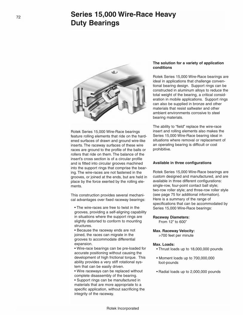
Rotek Incorporated
Rotek Series 15,000 Wire-Race bearingsfeature rolling elements that ride on the hard-ened surfaces of drawn and ground wire-likeinserts. The raceway surfaces of these wireraces are ground to the profile of the balls orrollers that ride on them. The balance of theinsert’s cross section is of a circular profileand is fitted into circular grooves machinedinto the support rings that comprise the bear-ing. The wire-races are not fastened in thegrooves, or joined at the ends, but are held inplace by the force exerted by the rolling ele-ments.
This construction provides several mechani-cal advantages over fixed raceway bearings:
• The wire-races are free to twist in thegrooves, providing a self-aligning capabilityin situations where the support rings areslightly distorted to conform to mountingstructures.• Because the raceway ends are notjoined, the races can migrate in thegrooves to accommodate differentialexpansion.• Wire-race bearings can be pre-loaded foraccurate positioning without causing thedevelopment of high frictional torque. Thisability provides a very stiff rotational sys-tem that can be easily driven.• Wire raceways can be replaced withoutcomplete disassembly of the bearing.• Support rings can be manufactured inmaterials that are more appropriate to aspecific application, without sacrificing theintegrity of the raceway.
The solution for a variety of applicationconditions
Rotek Series 15,000 Wire-Race bearings areideal in applications that challenge conven-tional bearing design. Support rings can beconstructed in aluminum alloys to reduce thetotal weight of the bearing, a critical consid-eration in mobile applications. Support ringscan also be supplied in bronze and othermaterials that resist saltwater and otherambient environments corrosive to steelbearing materials.
The ability to “field” replace the wire-raceinsert and rolling elements also makes theSeries 15,000 Wire-Race bearing ideal in situations where removal or replacement ofan operating bearing is difficult or cost prohibitive.
Available in three configurations
Rotek Series 15,000 Wire-Race bearings arecustom designed and manufactured, and areavailable in three different configurations:single-row, four-point contact ball style;two-row roller style; and three-row roller style(see page 75 for additional information).Here is a summary of the range of specifications that can be accommodated bySeries 15,000 Wire-Race bearings:
Raceway Diameters:From 12” to 600”
Max. Raceway Velocity:>700 feet per minute
Max. Loads:• Thrust loads up to 18,000,000 pounds
• Moment loads up to 700,000,000 foot-pounds
• Radial loads up to 2,000,000 pounds
Series 15,000 Wire-Race Heavy Duty Bearings
72
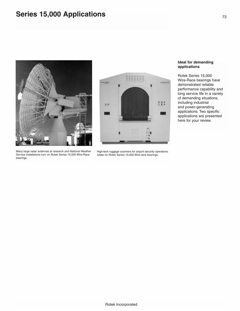
Rotek Incorporated
73Series 15,000 Applications
Ideal for demanding applications
Rotek Series 15,000 Wire-Race bearings have demonstrated reliable performance capability andlong service life in a varietyof demanding situations,including industrialand power-generating applications. Two specificapplications are presentedhere for your review.
High-tech luggage scanners for airport security operationsrotate on Rotek Series 15,000 Wire-race bearings.
Many large radar antennas at research and National WeatherService installations turn on Rotek Series 15,000 Wire-Racebearings.

Rotek Incorporated
Wire-Race Bearing Construction and Configurations
Typical Wire-Race bearing construction
Each configuration incorpo-rates common featuresdesigned to provide reliableperformance and maximizeservice life. Referring to theillustration above, thesedesign features include:
1. Steel raceway insertsWire-race inserts are manu-factured of hardened springsteel or hardened stainlesssteel (for maximum durabilityand resistance to corrosion.)
2. Support rings manufac-tured in materials appropri-ate for the applicationThe use of wire-race insertsallows supporting rings to bemanufactured in materialsthat may be more appropri-ate to a specific applicationthan the steel that machined
raceways require. Series15,000 Wire-Race bearingsare available with supportingrings of aluminum to reducebearing weight, bronze forsaltwater environments, anda variety of other materials.
3. Integral SealsIntegral seals are usuallyincorporated in the bearing toprevent bearing failurethrough abrasive contamina-tion and leaching away oflubricant.
4. Polymeric cages forrolling elementsRolling elements, eitherrollers or balls, are installedwith polymeric cages to avoidrolling element-to-rolling ele-ment contact and to assureproper spacing.
5. Rolling elements Rolling elements, ball orrollers, are often manufac-tured of hardened stainlesssteel to resist corrosion.
Integral gearing
Series 15,000 Wire-Racebearings can be suppliedwith integral external or inter-nal gearing, or gearless.
3
4
5 1 2
74

Rotek Incorporated
75
Available in various design configurations
Rotek Series 15,000 Wire-Race bearings are availablein many different configurations. Four-point ball typestyles are designed to use balls that roll within an x-shaped array of four wire-race inserts. Dual row configurations are also available.
Two-row roller style bearings have two rows of rollersthat are angled at 45˚ to the cross section’s verticalaxis, and roll between raceways formed by a triangulararray of wire-race inserts. This style of Wire-Racebearing offers greater radial stiffness than the balltype. Double row designs provide more uniform frictional characteristics under both normal (level) and tilting load conditions than a single-row four-pointball type.
Three-row roller style bearings incorporate three rowsof rollers, each traveling in its own set of wire-raceinserts. One row of rollers is axially (vertically) orient-ed to carry radial loads. The other two rows are radial-ly (horizontally) oriented to carry thrust and overturn-ing loads. This style of Wire-Race bearing is heavierand stiffer than, but not as resilient or accommodatingas, the two-row roller style and requires a more care-fully designed mounting structure.
Roller versus ball type bearings
Wire-Race bearings with rollers asrolling elements offer greater radial stiff-ness than bearings utilizing balls asrolling elements. This characteristic isimportant in situations where bearingsunder load are subject to sloping, suchas mobile applications. The greaterradial stiffness of roller bearings pro-vides more uniform torque characteris-tics under the localized loading associ-ated with slopes. The superior radialstiffness of the roller type bearing alsooffers higher resonant frequency char-acteristics. A high resonant frequencyis extremely important in applicationswhere servo control drive systems areused for stabilization or remote control.
We can supply you with completespecifications for any Wire-Racebearing
Rotek’s extensive design experienceand sophisticated CAD technology areavailable to assist you in the selectionof a Series 15,000 Wire-Race bearingthat is appropriate for your specificapplication. This service is availablewithout charge.
To start the design and selectionprocess, contact your local Rotek salesrepresentative or the Rotek applicationEngineering Department at 800/221-8043.
Wire-Race Bearing Construction and Configurations

Rotek Incorporated
Rotek Precision Bearings
Precision bearings are required for applications where critical tolerances exist for bearing fit, or when specific high performancefeatures and characteristics are required,such as:
- Precision positioning and repeatability
- Low tolerance axial or radial runouts
- Special stiffness or compliance characteristics
- Preload in the raceway system, coupled with a low torque requirement
- Gear precision > AGMA 10
Typical application where precision bearingsare either essential or desirable include:
- Precision rotary turntables for machine tools
- Index tables
- Robotics for precision positioning
- Medical diagnostic equipment
- Bottle filling equipment for beverage lines
- Radar and radio telescope antennas
- Test stands and testing equipment
The degree of precision in a bearing dependsprimarily on the accuracies attainable in themachining process. The need to machinebearing components to close tolerances ismost obvious in applications that require abearing with critical feature size or fit specifications.
Machining accuracy is also important to theperformance characteristics of equipment thatrequire positioning accuracy and repeatability.Rotek’s sophisticated machining capabilitiesproduce bearings with the concentricities, parallelism, flatness of surfaces and runoutsneeded to meet your most demanding precision positioning and repeatability requirements.
Here’s a summary of the capabilities and features of our line of large-diameterPrecision Bearings:
- Available in raceway diameters of 12” to 180”, with larger sizes available
- Available in three configurations• Single row, ball• Single row, roller with alternating axes
(cross-roller)• Three row, roller
- Minimum runout tolerances to within .0003” depending on raceway diameter and bearing configuration*
- Feature concentricities to within .0003”, depending on bearing diameter and configuration*
- Mounting surface flatness to within .0003”, depending on bearing diameter and configuration*
- Parellelism to within .0003”, depending on bearing diameter and configuration*
- Bolt hole positions to .010” diameter depending on bearing diameter and configuration.*
* Raceway diameter and configurations may affect capabilities. Check Rotek for details.
76
Rotek Incorporated
77Selecting a Rotek Precision Bearing
Although every applicationvaries to a degree, in general, your selection of aRotek Precision Bearingshould be based on five criteria:
- Accuracies
- Rotational speed
- Load capacity guidelines
- Bearing size limitations
- Life requirements
The ability of our PrecisionBearings to meet yourrequirements in these areasdepends primarily on thebearing’s cross section, raceway diameter, and type,size and number of rollingelements. The following is asummary of the differentseries we manufacture.
Series 3005P PrecisionBearings
Based on their overall capabilities, our Rotek Series3005P Precision Bearingsoffer the optimum combination of precision,economy, reliability and durability.
As an evolution of the classic, single row, four-pointcontact ball bearings design,our Series 3005P bearingsare practical for virtually anyheavy-duty application.Utilizing Rotek’s unique offsetraceway construction anddurable ball separators, theSeries 3005P provides thehighest degree of racewayconformity available.
The offset raceway keeps theload point at a constant distance from the edge of theraceway at both the front andrear of the application. Thisdistinctive design makes thehigh contact angle practical,resulting in the most efficientutilization of ball capacity.
Balls are separated by individual spacers or cages.Spacers and rolling elementsare loaded through loadingholes in one of the rings.These loading holes are, inmost cases, filled with closelyfitted plugs that conform tothe raceway contour.Conrad, or slot loaded styles,can also be supplied whenrequested.
Series 5005P PrecisionCross Roller Bearings
The Series 5005P CrossRoller Precision Bearings cansustain extreme radial, thrustand moment loads whetherapplied individually or incombination. The two rollerpaths in each ring, set in V-groove raceways, providefor this universal load carrying capability.
The rollers within the Series5005P have a length slightlyless than their diameter, andare positioned between therings so the adjacent rollerscontact a different raceway.Therefore, the axes of adjacent rollers are always atright angles to each other.By alternating rollers in thismanner, half of the rollerstransmit the load in onedirection and the other halftransmit the load in the opposite direction.
The advantage of this crossroller bearing construction isgreater stiffness - resulting ina lower spring rate. Thismakes the Series 5005Pideal in situations such asmachine tool applicationswhere deflection under loadmust be minimized.
The Rotek Cross RollerBearing Series can also havea higher theoretical dynamiccapacity per unit size than asingle row ball bearing.However, mounting structureconsiderations are criticalwhen utilizing Series 5005Pbearings because of the possibility of severe torquepenalties.
Series 10,005P PrecisionBearings
Equipped with three independent rows of rollers,separated by either steelcages or individual plasticspacers, the Series 10,005PPrecision Bearings offermore capacity per unit sizethan any other Rotek design.
Since all loadings are transmitted directly by raceway surfaces perpendicular to the loaddirection, the capacity ofeach rolling element andraceway surface within theSeries 10,005P is utilized inthe most efficient manner.
With this three roller design,there is no separating forceand minimal deflection, whichmakes the Series 10,005Pthe stiffest construction styleRotek has ever produced. Inaddition, the Series 10,005Poffers the lowest frictionaltorque of all our Rotek bearings, under most loadconditions.
Since the three row rollerbearing is capable of transmitting very high loadings, it is necessary for itto be mounted on a structuresufficiently uniform in stiffness. This ensures properly distributed loadingaround the bearing. Overall,the Series 10,005P PrecisionBearings provide the optimum combination of minimum runout, maximumstiffness, low friction, long lifeand high reliability.

Rotek Incorporated
Rotek Precision Bearing Selection Chart
This chart contains addition-al information to help youselect the right RotekPrecision Bearing for yourspecific applilcation
Note: For information onRotek Precision Bearingswith raceway diameters over60 inches, contact ourApplication EngineeringDepartment.
For assistance in determiningwhich Rotek PrecisionBearing should be specifiedfor your application, or for adetailed drawing of a specificbearing, contact ourApplication EngineeringDepartment at 800/221-8043.
Series
3005P
5005P
10,005P
TypicalCross Section
78

Rotek Incorporated
ConstructionConfiguration
Single row ball, four pointcontact with offset racewaysfor combined thrust,moment and radial loading.
Single row roller with alternating axes. Crossroller bearing providesgreatest theoretical dynamiccapacity per unit size.
Three row roller, heavy-dutybearing with greatestcapacity per unit size. Moststringent requirement formounting structure.
Typical Design
AvailableRaceway
Diameters
12” - 180”
12” - 180”
12” - 180”
Raceway
12”20”30”40”50”60”
12”20”30”40”50”60”
20”30”40”50”60”
Tolerance
.0003”
.0003”
.0003”
.0003”
.0004”
.0006”
.0003”
.0003”
.0003”
.0003”
.0003”
.0003”
.0003”
.0003”
.0003”
.0003”
.0003”
Minimum Runout Tolerance AtSelected Raceway Diameters
79Rotek Precision Bearing Selection Chart