
A three-dimensional numerical approach on water entry...
10
Contents lists available at ScienceDirect Ocean Engineering journal homepage: www.elsevier.com/locate/oceaneng A three-dimensional numerical approach on water entry of a horizontal circular cylinder using the volume of fluid technique A. Iranmanesh, M. Passandideh-Fard ⁎ Mechanical Engineering Department, Ferdowsi University of Mashhad, Mashhad, Iran ARTICLE INFO Keywords: Water entry Volume of fluid (VOF) Horizontal circular cylinder Free-surface flows ABSTRACT In this paper, complicated hydrodynamics of a horizontal circular cylinder entering water is investigated numerically for low Froude numbers. A numerical approach is used to model the solid-liquid interactions in presence of a free-surface. The governing equations for the 3D incompressible fluid flow are continuity and Navier-Stokes equations along with an equation for the free surface advection. To track the free-surface motion, the fast-fictitious-domain method is integrated into the volume-of-fluid (VOF) technique. The governing equations are solved everywhere in the computational domain including the horizontal cylinder. A rigid body motion is applied to the region occupied by the circular cylinder. The no-slip boundary condition on the solid- liquid interface is exerted implicitly via increasing the viscosity of the region occupied by the solid. To validate the numerical scheme, the results are compared with those of the experiments available in the literature. The effects of cylinder diameter, length, impact velocity, and cylinder-water density ratio on the non-dimensional depth are also investigated. 1. Introduction Water entry problems have been studied theoretically and experi- mentally by many researchers and scientists for more than a century due to their extensive applications in numerous industries especially ocean and coastal engineering. Some water entry applications are namely: hydrodynamic loading on ships, ship slamming, launching of torpedoes, see-landing of aerial vehicles, missile projectiles’ impact upon entering water, and even steel-making processes. However, cavity formation behind the solid object and capillary effects at the contact line between the surface of the solid and liquid complicates the understanding and analysis of this phenomenon. Worthington and Cole (1897) presented an initial image of water impact cavity and splash by using single-spark photography. Water entry of vertical spherical objects was studied systematically by Worthington (1908). The solid-liquid interaction knowledge was im- proved comprehensively by later studies. Watanabe (1934) performed a quantitative experimental work to measure the impact force on an object upon entering water. The effect of various surface conditions of a sphere on the cavity formed during its water entry was investigated by May (1951). He also conducted (May, 1952) many experiments to analyze the effect of various parameters on the cavity which formed behind the solid. The effect of atmospheric pressure, solid velocity, and surface tension on the entry of spheres into water was studied by Gilbarg and Andersok (1948). It was concluded that the closure of splash was mostly dependent on an increase in atmospheric density and solid velocity. They also found that the splash closure was influenced by surface tension only in cases where the solid radius, velocity, and the atmospheric density are small. Several experiments were performed by Abelson (1970) to investigate pressure drop behind a solid object moving inside a liquid. The initial force of the impact on a sphere striking a liquid surface was estimated experimentally by Moghisi and Squire (1981). They also improved the correlation for the drag coefficient of a sphere during its initial entry into a liquid. Greenhow and Lin (1983) presented typical images for the free surface deformation during the water entry of two-dimensional cylinders. They assumed the length of the cylinder to be nearly the same as that of the tank to create a two-dimensional cavity following the cylinder impact. A whole cavity evolution for a horizontal cylinder was not created in their experiments since the depth of water was supposed to be shallow. Hu and Koterayama (1996) experimentally and numerically investi- gated the hydrodynamic forces acting on a rectangular cylinder and a circular cylinder undergoing slow drift oscillation in regular waves. The viscous flow around a two-dimensional oscillating cylinder was mod- elled using a finite-difference method. Lee et al. (1997) considered the effect of Bernoulli pressure and surface tension on the splash closure. They found that both inertia and gravity effects are relevant to the deep closure for water entry with low Froude numbers. Thoroddsen et al. http://dx.doi.org/10.1016/j.oceaneng.2016.12.018 Received 14 December 2015; Received in revised form 1 October 2016; Accepted 18 December 2016 ⁎ Corresponding author. E-mail addresses: [email protected] (A. Iranmanesh), [email protected] (M. Passandideh-Fard). Ocean Engineering 130 (2017) 557–566 0029-8018/ © 2016 Elsevier Ltd. All rights reserved. MARK
Transcript of A three-dimensional numerical approach on water entry...
Contents lists available at ScienceDirect
Ocean Engineering
journal homepage: www.elsevier.com/locate/oceaneng
A three-dimensional numerical approach on water entry of a horizontalcircular cylinder using the volume of fluid technique
A. Iranmanesh, M. Passandideh-Fard⁎
Mechanical Engineering Department, Ferdowsi University of Mashhad, Mashhad, Iran
A R T I C L E I N F O
Keywords:Water entryVolume of fluid (VOF)Horizontal circular cylinderFree-surface flows
A B S T R A C T
In this paper, complicated hydrodynamics of a horizontal circular cylinder entering water is investigatednumerically for low Froude numbers. A numerical approach is used to model the solid-liquid interactions inpresence of a free-surface. The governing equations for the 3D incompressible fluid flow are continuity andNavier-Stokes equations along with an equation for the free surface advection. To track the free-surface motion,the fast-fictitious-domain method is integrated into the volume-of-fluid (VOF) technique. The governingequations are solved everywhere in the computational domain including the horizontal cylinder. A rigid bodymotion is applied to the region occupied by the circular cylinder. The no-slip boundary condition on the solid-liquid interface is exerted implicitly via increasing the viscosity of the region occupied by the solid. To validatethe numerical scheme, the results are compared with those of the experiments available in the literature. Theeffects of cylinder diameter, length, impact velocity, and cylinder-water density ratio on the non-dimensionaldepth are also investigated.
1. Introduction
Water entry problems have been studied theoretically and experi-mentally by many researchers and scientists for more than a centurydue to their extensive applications in numerous industries especiallyocean and coastal engineering. Some water entry applications arenamely: hydrodynamic loading on ships, ship slamming, launching oftorpedoes, see-landing of aerial vehicles, missile projectiles’ impactupon entering water, and even steel-making processes. However, cavityformation behind the solid object and capillary effects at the contactline between the surface of the solid and liquid complicates theunderstanding and analysis of this phenomenon.
Worthington and Cole (1897) presented an initial image of waterimpact cavity and splash by using single-spark photography. Waterentry of vertical spherical objects was studied systematically byWorthington (1908). The solid-liquid interaction knowledge was im-proved comprehensively by later studies. Watanabe (1934) performeda quantitative experimental work to measure the impact force on anobject upon entering water. The effect of various surface conditions of asphere on the cavity formed during its water entry was investigated byMay (1951). He also conducted (May, 1952) many experiments toanalyze the effect of various parameters on the cavity which formedbehind the solid. The effect of atmospheric pressure, solid velocity, andsurface tension on the entry of spheres into water was studied by
Gilbarg and Andersok (1948). It was concluded that the closure ofsplash was mostly dependent on an increase in atmospheric densityand solid velocity. They also found that the splash closure wasinfluenced by surface tension only in cases where the solid radius,velocity, and the atmospheric density are small. Several experimentswere performed by Abelson (1970) to investigate pressure drop behinda solid object moving inside a liquid. The initial force of the impact on asphere striking a liquid surface was estimated experimentally byMoghisi and Squire (1981). They also improved the correlation forthe drag coefficient of a sphere during its initial entry into a liquid.Greenhow and Lin (1983) presented typical images for the free surfacedeformation during the water entry of two-dimensional cylinders. Theyassumed the length of the cylinder to be nearly the same as that of thetank to create a two-dimensional cavity following the cylinder impact.A whole cavity evolution for a horizontal cylinder was not created intheir experiments since the depth of water was supposed to be shallow.Hu and Koterayama (1996) experimentally and numerically investi-gated the hydrodynamic forces acting on a rectangular cylinder and acircular cylinder undergoing slow drift oscillation in regular waves. Theviscous flow around a two-dimensional oscillating cylinder was mod-elled using a finite-difference method. Lee et al. (1997) considered theeffect of Bernoulli pressure and surface tension on the splash closure.They found that both inertia and gravity effects are relevant to the deepclosure for water entry with low Froude numbers. Thoroddsen et al.
http://dx.doi.org/10.1016/j.oceaneng.2016.12.018Received 14 December 2015; Received in revised form 1 October 2016; Accepted 18 December 2016
⁎ Corresponding author.E-mail addresses: [email protected] (A. Iranmanesh), [email protected] (M. Passandideh-Fard).
Ocean Engineering 130 (2017) 557–566
0029-8018/ © 2016 Elsevier Ltd. All rights reserved.
MARK

(2004) worked on the horizontal jetting ejected from the impact pointof a sphere with a high velocity at the initial stage. It was found that thisinitial axisymmetric jetting spreads radially outwards at a speed of upto 30 times of the sphere velocity. They also concluded that the initialjetting forms within mostly 100 µs from the first contact of the sphereon water. Experimental-theoretical studies for water entry of hydro-phobic spheres and vertical cylinders were presented by Aristoff andBush (2009) and Aristoff et al. (2010). A regime diagram for hydro-phobic spheres with the same wetting properties based on non-dimensional parameters affecting the cavity formation behind thesphere were also presented. A theoretical model for predicting keyparameters namely the depth and time of pinch-off, depth of sphere atthe pinch-off time and volume of cavity behind the sphere were alsodeveloped.
A new Lagrange-multiplier based on the fictitious-domain methodfor the direct numerical simulation of fluid-solid interaction wasproposed by Glowinski et al. (1999). They also utilized this multiplierfor fluidization, sedimentation, and many other applications(Glowinski et al., 1999, 2001; Glowinski, 2003). The fast computationscheme proposed by Patankar (2001) was used by Patankar andSharma (2005) to simulate rigid particulate flows. In this method,computation domain included both solid and liquid and the governingequations were solved everywhere. The solid velocity was calculated byintegrating in the solid zones since the total linear and angular momentin each individual solid zone was supposed to be conserved. Zhu et al.(2006) numerically analyzed the water entry and exit of a horizontalcircular cylinder with both forced and free vertical motions using theConstrained Interpolation Profile (CIP) method. The governing equa-tions were solved numerically on a non-uniform, staggered Cartesiangrid. The numerical results of the free-surface deformation, the verticalmotion of the cylinder as well as the water entry and exit forces werecompared with the experimental results. Hu and Sueyoshi (2010)introduced two numerical approaches namely the CIP-based Cartesiangrid method and the MPS method to simulate the strongly nonlinearwave-body interaction problems such as ship motions and green-waterimpact on deck. The numerical results were validated with experi-mental data for a dam break problem. An experimental investigation ofthe trajectories, forces, and cavity formation behind spinning hydro-phobic and hydrophilic spheres were presented by Techet and Truscott(2011). Several cases were presented for non-spinning spheres includ-ing half hydrophobic and half hydrophilic. They concluded that thespin induced less lateral forces compared to asymmetrical cavityformation. Mirzaii and Passandideh-Fard (2012) developed a 2Dnumerical algorithm for simulating the interactions between a liquidand a solid object in presence of a free-surface. The fast-fictitious-domain method was integrated into the volume of fluid (VOF)technique to track the free surface motion. The model was also usedto simulate the free fall of one and two circular particles inside a liquid.Two-dimensional numerical simulations of the water entry and exit ofhorizontal circular cylinders at a constant velocity were described byHafsia et al. (2009). The simulated results were compared with thenumerical results of Lin (2007). The free surface deformation aroundthe cylinder in the downward direction was accurately predicted. Aproposed experimental setup for characterizing the vertical motion of ahorizontal circular cylinder through a free surface was presented byGoharzadeh and Molki (2012). Their experimental results gave insighton hydrodynamic impact phenomena and surface waves. Yang and Qiu(2012a, 2012b) investigated 3D slamming problems for water entry ofsolid bodies with vertical and oblique velocities using the CIP method.A pressure-based algorithm was introduced for non-advection calcula-tions while the advection terms were modelled by the 3D CIP method.They also calculated hydrodynamic forces on a wedge, a cusped body,and a sphere and compared the numerical results with those of theexperiments. Yang and Qiu (2012a, 2012b) calculated slamming forceson 2D and 3D bodies using the CIP method. The advection terms werecalculated using a compact upwind scheme while the multiple phases
were simulated by a pressure-based algorithm. 2D wedges with dead-rise angles varying between 0 and 60◦ were considered to validate thenumerical scheme. Their 2D model was extended to 3D and wasapplied for simulating a cylinder and a catamaran entering calm water.Lue et al. (2012) studied experimentally and numerically the slammingload and response of complex steel wedge with a deadrise angle of 22◦.They measured impact acceleration, slamming pressure, and stressresponses and compared the results with those of the simulations. Theyfound that the numerical model well predicted the stress trends and itsmaximum. Ryzhakov et al. (2013) investigated the behavior of the sea-landing of an unmanned aerial vehicle using the Particle FiniteElement Method. They reported the maximum load exerted upon thefloats to vary between 4 and 6 kN depending on water accumulation inthe vehicle. Three assumptions of water accumulation (front, rear,lateral) were also considered. They found the vehicle to be stable andfloatable in all scenarios. Larsen (2013) studied the possibility of waterentry problems using the CD-adapco CFD-software STAR-CCM+ with afocus on circular cylinders. Two scenarios were considered, a cylinderwith a constant velocity and a free-falling cylinder. He also comparedthe numerical results of three-dimensional water impact of a cylinderwith 8° impact angle with those of experiments and a good agreementwas observed. Gu et al. (2014) simulated water entry of solid objectswith various shapes and configurations by applying the Navier-Stokesequations on a fixed Cartesian grid. The level set method was used tocapture the free surface deformation. Moving objects were modelledusing the partial cell method combined with a local relative velocityapproach. They modelled vertical and oblique water entry of wedgeswith different heel angles and compared the results with those of thesimulations available in the literature. Wang and Soares (2014) studiedthe water impact of three-dimensional buoys by an explicit finiteelement method with an Arbitrary-Lagrangian Eulerian solver. Thefluid-solid interface was modelled using the VOF method. The con-vergence studies were achieved for three dimensional hemisphere andcones with various deadrise angles. The numerical results were foundto be highly influenced by the domain mesh size. Abraham et al. (2014)numerically evaluated the forces and motions of a sphere falling on awater surface from an elevation above the free-surface. They concludedthat the drag force was highly dependent on the momentum transferfrom the sphere to the adjacent liquid. Three-dimensional effects onwater entry of the horizontal cylinders were investigated by Wei andHu (2014). They examined four length to diameter ratios, two cylinder-water density ratios, and two falling heights in their experiments. Theeffect of diameter on the cylinder depth, however, was not considered.They concluded that the measured jetting speeds for all studied caseswere approximately equal at the initial stage since the kinetic energy ofthe flow was nearly two-dimensional. A numerical study on thedynamic response of a generic rigid water-landing object during waterimpact was presented by Challa et al. (2014). They validated thenumerical results with those of the experiments. They investigated awide range of conditions considering variations in vertical velocity,entry angle, and object weight. The numerical results showed that thefirst coupled Fluid-Structure Interaction (FSI) model could capture thewater-impact response accurately for all range of drop tests considered.A detailed study on the local pressures acting on the surface of a quasi-rigid cylinder during vertical water entry into a flat water surface wasaccomplished by Nuffel et al. (2014). Their works encompassed theimpact pressure results of a large set of slamming drop experimentwith a cylindrical model. They found that for deadrise angles largerthan 4.25°, the Wagner theory (Wagner, 1932) was a good approxima-tion for impact pressures acting on a horizontal rigid cylinder duringvertical water entry. A series of experimental studies on water entry ofcircular cylinders with inclined angles was presented by Wei and Hu(2015). They focused on the effect of inclined angles as well as densityand length-to-diameter ratios. Both quantitative and qualitative ana-lyses were carried out based on the experimental results. They reportedthat the cylinder with a lower inclined angle experienced a larger drag
A. Iranmanesh, M. Passandideh-Fard Ocean Engineering 130 (2017) 557–566
558
force. Panciroli et al. (2015) performed several experiments on waterentry of curved rigid wedges with deadrise angles of 25° and 35° as wellas varying radius of curvature. They varied the drop height to study theeffects of the impact velocity on the pile-up evolution, the impactdynamics, and the energy transferred to the fluid. It was found thatbetween 60% and 80% of the impact energy was transferred to the risenwater which formed the pile-up and the spray jets. Erfanian et al.(2015) studied experimentally and numerically the water entry of aspherical-nose projectile. A Coupled Eulerian-Lagrangian method wasused to model the fluid-structure interaction. They compared the cavityshape and the projectile trajectory of the numerical results with thoseof the experiments where good agreement was observed. Wen and Qiu(2016) simulated two-dimensional water entry of a wedge, a shipsection, and a circular cylinder using the CIP method. They defineddensity functions to capture the interface between solid, water, and air.
In this paper, a three-dimensional numerical approach is developedto obtain the cavity formed behind a horizontal circular cylinderimpacting a free surface. The continuity and Navier-Stokes equationsare solved simultaneously along with the VOF method to track the free-surface. The solid body motion is generated by applying the conserva-tion of momentum within the solid to the region occupied by thecylinder. The numerical results are validated with experimental resultsboth quantitatively and qualitatively. Furthermore, the effects oflength, diameter, cylinder-water density ratio, and impact velocity onthe cylinder motion are also investigated.
2. Numerical method
2.1. Fluid flow
The continuity and Navier-Stokes equations in 3D, incompressible,Newtonian, and laminar flow are solved as the governing equations forfluid flow:
V∇. = 0⎯→⎯⎯
(1)
Vt
V Vρ
pρ
τρ
F∂∂
+ . ∇ = − 1 ∇ + 1 ∇. + 1b
⎯→⎯⎯⎯→⎯⎯ ⎯→⎯⎯ ←→ ⎯ →⎯⎯
(2)
τ μ V V= [(∇ ) + (∇ ) ]T←→ ⎯→⎯⎯ ⎯→⎯⎯(3)
where V⎯→⎯⎯
is the velocity vector, ρ the density, µ the dynamic viscosity, p
the pressure, τ←→
the stress tensor, and Fb⎯ →⎯⎯
stands for body forces per unitvolume acting on the fluid. It should be mentioned that for all casesconsidered in this study, the maximum Reynolds number for ahorizontal circular cylinder entering water is 3.09×10⁵; therefore, theflow can be assumed laminar.
A two-step projection method (Passandideh-Fard et al., 2002) isused to solve the continuity and momentum equations in two fractional
steps. In the first step, Vn⎯→⎯⎯ +1/2
is obtained by discretizing the convectiveand body force terms explicitly.
V VΔt
V Vρ
μ V Vρ
F− = −( . ∇ ) + 1 ∇. [(∇ ) + (∇ ) ] + 1n n
nn
n nT
n b
n⎯→⎯⎯ +1/2 ⎯→⎯⎯
⎯→⎯⎯ ⎯→⎯⎯ ⎯→⎯⎯ ⎯→⎯⎯ ⎯ →⎯⎯
(4)
In Eq. (4), superscript (n) specifies the quantity magnitude at theold time level and Δt is the time step size. By employing explicitdiscretization for viscous terms, a first temporary velocity is calculated.
Finally, the following equation must be solved to obtain velocity
vector at the new time level (Vn⎯→⎯⎯ +1
).
V VΔt ρ
p− = − 1 ∇n n
nn
⎯→⎯⎯ +1 ⎯→⎯⎯ +1/2
+1(5)
If divergence operator is applied to right and left sides of Eq. (5)
and the continuity equation is used, the pressure Poisson equation willbe obtained as following:
⎡⎣⎢
⎤⎦⎥ρ
p VΔt
∇. 1 ∇ = ∇n
n
n
+1
⎯→⎯⎯ +1/2
(6)
Incomplete Cholesky-Conjugate Gradient (ICCG) solver (Kershaw,1978) is selected to solve the resulting equation by which the pressureis obtained. This pressure is next used to calculate the final velocity atthe next time level (n+1) using Eq. (5).
To track the interface, the VOF method is used where a scalar field(f), the so-called liquid volume fraction, is defined:
⎧⎨⎪⎩⎪
f =0 in gas or solid0 < , < 1 at liquid interface1 inside liquid (7)
It should be noted that f is defined as the fraction of total volume ofa cell occupied by liquid. Therefore, f is the volume of liquid in a celldivided by the total volume of the cell (not divided by the combinedvolume of liquid and gas).
Once the new velocity field is computed, values of f are obtained bysolving an advection equation for volume fraction:
dfdt
ft
V f S= ∂∂
+ . ∇ =⎯→⎯⎯
(8)
where S represents the mass transfer term which is supposed to be zeroin this study. Eq. (8) is solved based on the Youngs PLIC algorithm totrack the interface (Youngs, 1984).
Landau and Lifschitz (1987) suggested the following boundarycondition at the moving liquid/gas interface:
p p σκ n τ τ n σx
( − − ) = ( − ) + ∂∂l g i l ik g ik k
i, ,
(9)
The pressures on the liquid and gas sides of the interface are
defined by pl and pg, respectively. A component of the unit normal n∧
directed into the interface is represented by ni; σ stands for the surfacetension; κ is the local total curvature; and τl ik, and τg ik, are shear stressesin liquid and gas, respectively. To simplify the above-mentionedequation, the surface tension is supposed to be constant while theshear stresses are assumed zero to satisfy the interface boundarycondition. Thus, Eq. (9) is reduced to Laplace equation as following:
p p σκ− =l g (10)
Instead of using Eq. (10) as a boundary condition for the pressure
field, the surface tension is reformulated as a body force ( FST⎯ →⎯⎯⎯⎯⎯⎯⎯
) basedon the Continuum Surface Force (CSF) model proposed by Brackbillet al. (1992). The following equation is suggested by Aleinov andPuckett (1995):
F σκ AV
n=ST⎯ →⎯⎯⎯⎯⎯⎯⎯ ∧
(11)
where V is the cell volume and A is the surface area of the fluid
contained within the cell. κ and n∧are calculated using the following
relations:
κ n= −∇.∧ (12)
n ff
= ∇∇
∧
(13)
The body force calculated from this methodology is substituted intoEq. (4) to consider the effect of surface tension.
2.2. Solid object
The fast-fictitious-domain method is used to model the solid object.To satisfy the no-slip boundary condition on the solid-liquid interface,
A. Iranmanesh, M. Passandideh-Fard Ocean Engineering 130 (2017) 557–566
559

a high viscosity is attributed to the solid zone. As the first step for thismethod, the governing equations are solved everywhere including thesolid object without any further considerations. As the second step, therigid body motion of the solid object can be imposed based on the factthat the total angular and linear momentum in the solid body must beconserved in each time step. To resolve an unrealistic slip condition inthe solid-liquid interface, a high viscosity is attributed to the solid zone.The computation procedure applied in this paper is organized asfollows:
(1) A scalar parameter (φs) is used to describe the solid object withinthe computational domain. (φs) is defined as the fraction of totalvolume of a cell occupied by solid. In other words, (φs) is thevolume of solid in a cell divided by the total volume of the cell (notdivided by the combined volume of liquid and gas)
⎧⎨⎪⎩⎪
φout of solidsolid boundarywithin solid
=00 < , < 11
s
(14)
(2) The governing equations are solved everywhere even within thesolid zone. The density and viscosity are calculated in each cell asfollows
ρ fρ f φ ρ φ ρ= + (1 − − ) +l s g s s (15)
μ fμ f φ μ φ μ= + (1 − − ) +l s g s s (16)
where liquid, gas and solid are represented by l, g, and srespectively. Based on Mirzaii and Passandideh-Fard (2012), using aviscosity two orders of magnitude lager than that of the fluid is largeenough to accurately model the solid-liquid interaction.(3) The following integrals are used to calculate the average rotational
and angular velocity based on the conservation of momentumwithin the solid
∫M V ρ V d= ∀s ssolid zone
⎯→⎯⎯ ⎯→⎯⎯
(17)
∫I ω r ρ V d= × ∀s ssolid zone
⎯ →⎯⎯ → ⎯→⎯⎯
(18)
where the solid mass, moment of inertia, translational velocity, and
angular velocity are indicated by Ms, Is, Vs⎯→⎯⎯, ωs
⎯ →⎯⎯respectively. ∀ and r
→are
the solid volume and position vector with respect to the solid center ofthe mass. The next velocity is calculated as follows:
V V ω r= + ×solid zone s⎯→⎯⎯ ⎯→⎯⎯ ⎯ →⎯⎯ →
(19)
To eliminate the need for applying an additional force term to the
solid zone, the viscosity of the solid zone is increased and so, Vn⎯→⎯⎯ +1
is
supposed to be equal with Vsolid zone⎯→⎯⎯
. A flowchart of the sequence of thecomputational cycle for velocity, and fluid-solid volume fractions isshown in Fig. 1.
3. Results and discussions
Three-dimensional numerical results for water entry of a horizontalcylinder are presented in this section. To show the three-dimensionaleffects more clearly, the results are displayed from both the front andside views. To validate the numerical model, the results are comparedwith those available in the literature. Furthermore, the effects ofvarious parameters namely solid density, initial impact velocity, lengthand diameter on the cylinder depth are studied. Numerical computa-tions were performed on an Intel(R) 3.5 GHz CPU XP desktop. Thecomputation times ranged from 5 to 8 days.
3.1. Water entry of a cylinder
In this section, the water entry of a horizontal cylinder is discussedboth numerically and experimentally. To simulate the water entry of acylinder, four non-dimensional parameters are required: Reynoldsnumber Re=U0d/ν, Weber number W ρU R σ= /0
20 , Bond number
B ρgR σ= /02 , and Froude number Fr U gd= /0 . Here, U0, d, ν stand
for the impact velocity, cylinder diameter, and fluid kinematic viscosity(ν≈10−6 m2/s) respectively. Fluid density and surface tension, andcylinder radius are represented by ρ≈1000 kg/m3, σ≈0.07 N/m, andR0. The density ratio of the solid to water is defined as D=ρsolid/ρwater.The experimental results used to validate the numerical model arethose reported by Wei and Hu (2014) with the following specifications:
1. Cylinder length (L): 200 mm.2. Cylinder diameter (d): 50 mm.3. Initial position of the cylinder center: 25 mm above the water
surface.4. Impact velocity (U0): 6.22 m/s.5. Solid density: 1370 kg/m3.
The cylinder is released from a height of 2 m in the experiment (Weiand Hu, 2014); when the cylinder touches the free-surface, its impactvelocity is 6.22 m/s. At this moment, the initial position of the cylindercenter is 25 mm above the free-surface (since the cylinder diameter is
Fig. 1. Flowchart of the sequence of the computational cycle for velocity, and fluid-solidvolume fractions.
A. Iranmanesh, M. Passandideh-Fard Ocean Engineering 130 (2017) 557–566
560
50 mm).The values of non-dimensional parameters used in the experiments
are displayed in Table 1.A schematic diagram of the computational domain for the water
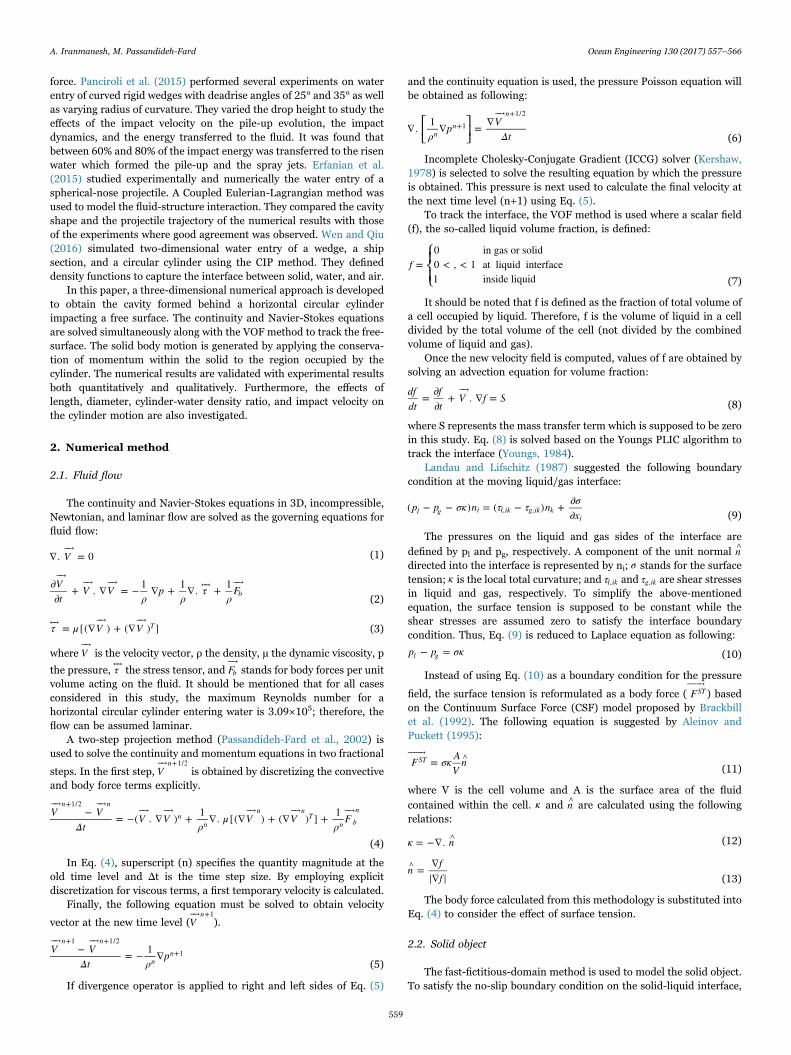
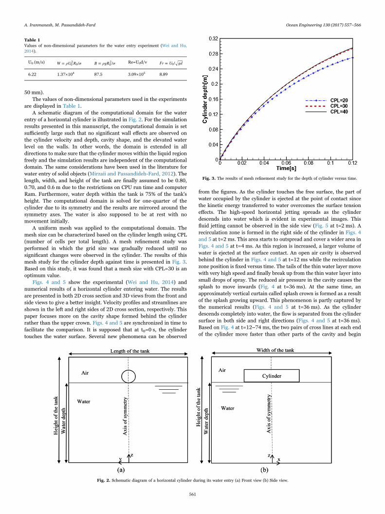
entry of a horizontal cylinder is illustrated in Fig. 2. For the simulationresults presented in this manuscript, the computational domain is setsufficiently large such that no significant wall effects are observed onthe cylinder velocity and depth, cavity shape, and the elevated waterlevel on the walls. In other words, the domain is extended in alldirections to make sure that the cylinder moves within the liquid regionfreely and the simulation results are independent of the computationaldomain. The same considerations have been used in the literature forwater entry of solid objects (Mirzaii and Passandideh-Fard, 2012). Thelength, width, and height of the tank are finally assumed to be 0.80,0.70, and 0.6 m due to the restrictions on CPU run time and computerRam. Furthermore, water depth within the tank is 75% of the tank'sheight. The computational domain is solved for one-quarter of thecylinder due to its symmetry and the results are mirrored around thesymmetry axes. The water is also supposed to be at rest with nomovement initially.
A uniform mesh was applied to the computational domain. Themesh size can be characterized based on the cylinder length using CPL(number of cells per total length). A mesh refinement study wasperformed in which the grid size was gradually reduced until nosignificant changes were observed in the cylinder. The results of thismesh study for the cylinder depth against time is presented in Fig. 3.Based on this study, it was found that a mesh size with CPL=30 is anoptimum value.
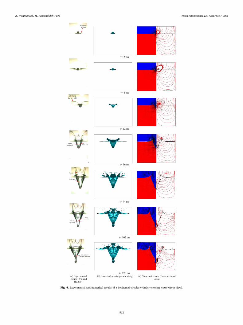
Figs. 4 and 5 show the experimental (Wei and Hu, 2014) andnumerical results of a horizontal cylinder entering water. The resultsare presented in both 2D cross section and 3D views from the front andside views to give a better insight. Velocity profiles and streamlines areshown in the left and right sides of 2D cross section, respectively. Thispaper focuses more on the cavity shape formed behind the cylinderrather than the upper crown. Figs. 4 and 5 are synchronized in time tofacilitate the comparison. It is supposed that at t0=0 s, the cylindertouches the water surface. Several new phenomena can be observed
from the figures. As the cylinder touches the free surface, the part ofwater occupied by the cylinder is ejected at the point of contact sincethe kinetic energy transferred to water overcomes the surface tensioneffects. The high-speed horizontal jetting spreads as the cylinderdescends into water which is evident in experimental images. Thisfluid jetting cannot be observed in the side view (Fig. 5 at t=2 ms). Arecirculation zone is formed in the right side of the cylinder in Figs. 4and 5 at t=2 ms. This area starts to outspread and cover a wider area inFigs. 4 and 5 at t=4 ms. As this region is increased, a larger volume ofwater is ejected at the surface contact. An open air cavity is observedbehind the cylinder in Figs. 4 and 5 at t=12 ms while the recirculationzone position is fixed versus time. The tails of the thin water layer movewith very high speed and finally break up from the thin water layer intosmall drops of spray. The reduced air pressure in the cavity causes thesplash to move inwards (Fig. 4 at t=36 ms). At the same time, anapproximately vertical curtain called splash crown is formed as a resultof the splash growing upward. This phenomenon is partly captured bythe numerical results (Figs. 4 and 5 at t=36 ms). As the cylinderdescends completely into water, the flow is separated from the cylindersurface in both side and right directions (Figs. 4 and 5 at t=36 ms).Based on Fig. 4 at t=12–74 ms, the two pairs of cross lines at each endof the cylinder move faster than other parts of the cavity and begin
Table 1Values of non-dimensional parameters for the water entry experiment (Wei and Hu,2014).
U0 (m/s) W ρU R σ= /02
0 B ρgR σ= /02 Re=U0d/ν Fr U gd= /0
6.22 1.37×10⁴ 87.5 3.09×10⁵ 8.89
Fig. 2. Schematic diagram of a horizontal cylinder during its water entry (a) Front view (b) Side view.
Fig. 3. The results of mesh refinement study for the depth of cylinder versus time.
A. Iranmanesh, M. Passandideh-Fard Ocean Engineering 130 (2017) 557–566
561
t= 2 ms
t= 4 ms
t= 12 ms
t= 36 ms
(c) Numerical results (Cross sectional area)
t= 74 ms
t= 102 ms
t= 120 ms(a) Experimental results (Wei and
Hu,2014)
(b) Numerical results (present study)
Fig. 4. Experimental and numerical results of a horizontal circular cylinder entering water (front view).
A. Iranmanesh, M. Passandideh-Fard Ocean Engineering 130 (2017) 557–566
562

t= 2 ms
t= 4 ms
t= 12 ms
t= 36 ms
t= 74 ms
t= 102 ms
t= 120 ms(a) Experimental results
(Wei and Hu,2014)(b) Numerical results (present study) (c) Numerical results (Cross sectional
area)
Fig. 5. Experimental and numerical results of a horizontal circular cylinder entering water (side view).
A. Iranmanesh, M. Passandideh-Fard Ocean Engineering 130 (2017) 557–566
563

approaching each other. In Figs. 4 and 5 at t=102 ms, furtherrecirculation zones are generated both inside and outside the cavityand also the direction of streamlines are entirely changed. Therecirculation zone formed in front of the cylinder causes the cavitywalls approaching each other (Fig. 4 at t=102 ms). After the two pairsof cross lines close, two new cross lines are generated (Fig. 4 att=102 ms). They also move along the axis direction faster than otherparts of the cavity (Figs. 4 and 5 at t=102–120 ms). In Fig. 4 att=120 ms, the directions of streamlines are completely reversed. Therecirculation zone covers the entire right side of the cylinder in Fig. 5 att=120 ms. As shown in Fig. 5, the side wall of the cavity from theexperiments is smooth while there are some elevated streaks on thecavity wall from simulations. The small discrepancy between thecalculated images and experimental photos related to the cavity wallmay be attributed to the small roughness of the cylinder surface alongwith its corresponding contact angle variations in the experiments.Furthermore, the cavity shape inversion behavior cannot be seen in thenumerical results. The cavity shape inversion line is attributed to thereattachment of thin liquid films separated from the two ends of thecavity. Modeling thin liquid films needs extensive mesh refinementswhich will considerably increase the computational time. The flowseparation from the cylinder surface may be attributed to the surfaceconditions (small roughness and contact angle variations) which wasnot the focus of this manuscript.
The experimental (Wei and Hu, 2014) and numerical results arewell compared qualitatively. To present a quantitative comparison, thecylinder depth versus time are plotted in Fig. 6. As observed, the resultsof simulation agree well with those of the experiment. For early times,the small differences between the experimental and numerical resultscan be attributed to the assumptions used in numerical simulations. Inthe developed model, the surface of the cylinder is assumed to besmooth and hydrophobic. This means that no specific treatment is usedfor the contact angle between the solid and liquid. The free surface insharp edges tends to form a curvature because of the surface tensioneffects. This effect completely mimics the cases in which a hydrophobicsolid enters a liquid free surface (Mirzaii and Passandideh-Fard, 2012).
It should also be noted that errors in the measurement of impactvelocity in experiments have been reported in the literature. Wei andHu (2014) reported that the initial jetting speed error is estimated to bewithin 10%. Quantitative comparison between the experimental (Weiand Hu, 2014) and numerical depths of a horizontal circular cylinderentering water is presented in Table 2. As seen in this table, the
absolute errors between the above-mentioned depths are increasedover time, while the relative errors vary between 3% and 7% for theselected times in Table 2.
Maximum length of the cavity formed in experimental and numer-ical results are measured and compared with each other in Figs. 7 and 8from both front and side views, respectively. Based on Figs. 7 and 8, thedifference between the cavity length in numerical and experimentalresults is small from front and side views until t=75 ms. This difference
Fig. 6. Comparison between the experimental and theoretical depth versus time forwater entry of a horizontal cylinder.
Table 2Comparison between the experimental (Wei and Hu, 2014) and numerical (presentstudy) depths of a horizontal cylinder entering water.
Time (ms) 20 40 60 80 100 120
Numerical depth (m) 0.0881 0.1499 0.1984 0.2378 0.2698 0.2956Experimental depth (m) 0.0910 0.1576 0.2121 0.2542 0.2895 0.3177Absolute error (m) 0.0029 0.0077 0.0137 0.0164 0.0197 0.0221Relative error (%) 3.1868 4.8858 6.4592 6.4516 6.8048 6.9562
Fig. 7. Comparison between maximum length of cavity (front view) formed in experi-mental and numerical results.
Fig. 8. Comparison between maximum length of cavity (side view) formed in experi-mental and numerical results.
A. Iranmanesh, M. Passandideh-Fard Ocean Engineering 130 (2017) 557–566
564
is increased after t=75 ms. Moreover, maximum lengths of the cavity inthe front and side views are more than those in the experiment for alltimes.
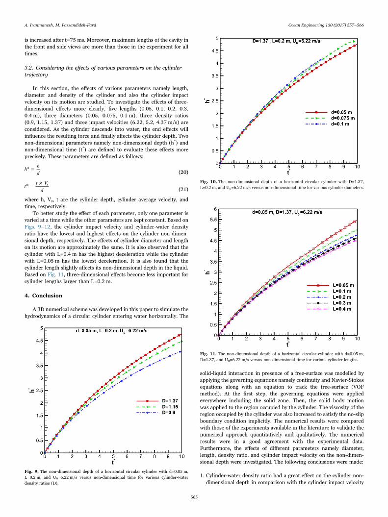
3.2. Considering the effects of various parameters on the cylindertrajectory
In this section, the effects of various parameters namely length,diameter and density of the cylinder and also the cylinder impactvelocity on its motion are studied. To investigate the effects of three-dimensional effects more clearly, five lengths (0.05, 0.1, 0.2, 0.3,0.4 m), three diameters (0.05, 0.075, 0.1 m), three density ratios(0.9, 1.15, 1.37) and three impact velocities (6.22, 5.2, 4.37 m/s) areconsidered. As the cylinder descends into water, the end effects willinfluence the resulting force and finally affects the cylinder depth. Twonon-dimensional parameters namely non-dimensional depth (h*) andnon-dimensional time (t*) are defined to evaluate these effects moreprecisely. These parameters are defined as follows:
h hd
* =(20)
t t Vd
* = × s(21)
where h, Vs, t are the cylinder depth, cylinder average velocity, andtime, respectively.
To better study the effect of each parameter, only one parameter isvaried at a time while the other parameters are kept constant. Based onFigs. 9–12, the cylinder impact velocity and cylinder-water densityratio have the lowest and highest effects on the cylinder non-dimen-sional depth, respectively. The effects of cylinder diameter and lengthon its motion are approximately the same. It is also observed that thecylinder with L=0.4 m has the highest deceleration while the cylinderwith L=0.05 m has the lowest deceleration. It is also found that thecylinder length slightly affects its non-dimensional depth in the liquid.Based on Fig. 11, three-dimensional effects become less important forcylinder lengths larger than L=0.2 m.
4. Conclusion
A 3D numerical scheme was developed in this paper to simulate thehydrodynamics of a circular cylinder entering water horizontally. The
solid-liquid interaction in presence of a free-surface was modelled byapplying the governing equations namely continuity and Navier-Stokesequations along with an equation to track the free-surface (VOFmethod). At the first step, the governing equations were appliedeverywhere including the solid zone. Then, the solid body motionwas applied to the region occupied by the cylinder. The viscosity of theregion occupied by the cylinder was also increased to satisfy the no-slipboundary condition implicitly. The numerical results were comparedwith those of the experiments available in the literature to validate thenumerical approach quantitatively and qualitatively. The numericalresults were in a good agreement with the experimental data.Furthermore, the effects of different parameters namely diameter,length, density ratio, and cylinder impact velocity on the non-dimen-sional depth were investigated. The following conclusions were made:
1. Cylinder-water density ratio had a great effect on the cylinder non-dimensional depth in comparison with the cylinder impact velocity
Fig. 9. The non-dimensional depth of a horizontal circular cylinder with d=0.05 m,L=0.2 m, and U0=6.22 m/s versus non-dimensional time for various cylinder-waterdensity ratios (D).
Fig. 10. The non-dimensional depth of a horizontal circular cylinder with D=1.37,L=0.2 m, and U0=6.22 m/s versus non-dimensional time for various cylinder diameters.
Fig. 11. The non-dimensional depth of a horizontal circular cylinder with d=0.05 m,D=1.37, and U0=6.22 m/s versus non-dimensional time for various cylinder lengths.
A. Iranmanesh, M. Passandideh-Fard Ocean Engineering 130 (2017) 557–566
565

for all times.2. The cylinder with the largest length experienced the highest
deceleration.3. The length effect was minor at the start time of the cylinder
submerge and as the time passed, this effect became more impor-tant.
4. Three-dimensional effects became less significant for cylinderlengths larger than 0.2 m.
5. Maximum lengths of the cavity in the front and side view were morethan those in the experiment for all times. Furthermore, thedifference between the cavity length in numerical and experimentalresults was small for front and side views until t=75 ms. Thisdifference increased after t=75 ms.
6. While the absolute difference between the measured and calculatedcylinder depths were increased in time, the relative errors variedbetween 3% and 7%.
Acknowledgements
The authors would like to acknowledge the high-performancecomputing (HPC) center of the Ferdowsi University of Mashhad.
References
Abelson, H.I., 1970. Pressure measurements in the water-entry cavity. J. Fluid Mech. 44,129–144.
Abraham, J., Gorman, J., Reseghetti, F., Sparrow, E., Stark, J., Shepard, T., 2014.Modeling and numerical simulation of the forces acting on a sphere during early-water entry. Ocean Eng. 76, 1–9.
Aleinov, I., Puckett, E.G., 1995. Computing surface tension with high-order kernels. In:Proceedings of the Sixth International Symposium on Computational Fluiddynamics, Lake Tahoe, NV, pp. 13–18.
Aristoff, J.M., Bush, J.W.M., 2009. Water entry of small hydrophobic spheres. J. FluidMech. 619, 45–78.
Aristoff, J.M., Truscott, T.T., Techet, A.H., Bush, J.W.M., 2010. The water entry ofdecelerating spheres. Phys. Fluids 22, 8.
Brackbill, J.U., Kothe, D.B., Zemach, C., 1992. A continuum method for modeling surfacetension. J. Comput. Phys. 100, 335–354.
Challa, R., Yim, S.C., Idichandy, V.G., Vendhan, C.P., 2014. Rigid-object water-entryimpact dynamics: Finite-element/smoothed particle hydrodynamics modeling andexperimental validation. J. Offshore Mech. Arct. Eng. 136, 031102–031112.
Erfanian, M.R., Anbarsooz, M., Rahimi, N., Zare, M., Moghiman, M., 2015. Numericaland experimental investigation of a three dimensional spherical-nose projectilewater entry problem. Ocean Eng. 104, 397–404.
Gilbarg, D., Andersok, R.A., 1948. Influence of atmospheric pressure on the phenomenaaccompanying the entry of spheres into water. J. Appl. Phys. 19, 127.
Glowinski, R., 2003. Numerical Methods for Fluids (Part 3). Elsevier Science B.V,
Amsterdam, The Netherlands.Glowinski, R., Pana, T.W., Hesla, T.I., Joseph, D.D., 1999. A distributed Lagrange
multiplier/fictitious domain method for particulate flows. Int. J. Multiphas. Flow. 25,755–794.
Glowinski, R., Pan, T.W., Hesla, T.I., Joseph, D.D., Periauxz, J., 2001. A fictitious domainapproach to the direct numerical simulation of incompressible viscous flow pastmoving rigid bodies: application to particulate flow. J. Comput. Phys. 169, 363–426.
Goharzadeh, A., Molki, A., 2012. Experimental study of water entry and exit of a circularcylinder at free surface, In: Proceedings of the ASME 2012 International MechanicalEngineering Congress and Exposition, IMECE2012, Texas, USA.
Greenhow, M., Lin, W.M. 1983. Nonlinear Free Surface Effects: Experiment and Theory.Rep. 83-19. Department of Ocean Engineering, MIT.
Gu, H.B., Qian, L., Causon, D.M., Mingham, C.G., Lin, P., 2014. Numerical simulation ofwater impact of solid bodies with vertical and oblique entries. Ocean Eng. 75,128–137.
Hafsia, Z., Mnasri, C., Mohamed, O., Maalel, K., 2009. Water entry and exit of horizontalcylinder in free surface flow. In: Proceedings of the International Symposium onConvective Heat and Mass Transfer in Sustainable Energy, Tunisia, April 26.
Hu, C., Koterayama, W., 1996. Slow drift damping force acting on a horizontal cylinder.J. Mar. Sci. Technol. 1, 105–113.
Hu, C., Sueyoshi, M., 2010. Numerical simulation and experiment on dam breakproblem. J. Mar. Sci. Appl. 9, 109–114.
Kershaw, D.S., 1978. The incomplete Cholesky–conjugate gradient method for theiterative solution of systems of linear equations. J. Comput. Phys. 26, 43–65.
Landau, L.D., Lifschitz, E.M., 1987. Fluid Mechanics second ed. Pergamon Press, Oxford.Larsen, E., 2013. Impact loads on circular cylinders. Inst. Mar. Tek..Lee, M., Longoria, R.G., Wilson, D.E., 1997. Cavity dynamics in high-speed water entry.
Phys. Fluids 9, 540.Lin, P., 2007. A fixed-grid model for simulation of a moving body in free surface flows.
Comput. Fluids 36, 549–561.Lue, H., Wang, H., Soares, C.G., 2012. Numerical and experimental study of
hydrodynamic impact and elastic response of one free-drop wedge with stiffenedpanels. Ocean Eng. 40, 1–14.
May, A., 1951. Effect of surface condition of a sphere on its water entry cavity. J. Appl.Phys. 22, 4.
May, A., 1952. Vertical entry of missiles into water. J. Appl. Phys. 23, 1362–1372.Mirzaii, I., Passandideh-Fard, M., 2012. Modeling free surface flows in presence of an
arbitrary moving object. Int. J. Multiphas. Flow. 39, 216–226.Moghisi, M., Squire, P.T., 1981. An experimental investigation of the initial force of
impact on a sphere striking a liquid surface. J. Fluid Mech. 108, 133–146.Nuffel, D.V., Vepa, K.S., Baere, I.D., Lava, P., Kersemans, M., Degrieck, J., Rouck, J.D.,
Paepegem, W.V., 2014. A comparison between the experimental and theoreticalimpact pressures acting on a horizontal quasi-rigid cylinder during vertical waterentry. Ocean Eng. 77, 42–54.
Panciroli, R., Shams, A., Porfiri, M., 2015. Experiments on the water entry of curvedwedges: high speed imaging and particle image velocimetry. Ocean Eng. 94,213–222.
Passandideh-Fard, M., Chandra, S., Mostaghimi, J., 2002. A three dimensional model ofdroplet impact and solidification. Int. J. Heat. Mass Transf. 45, 2229–2242.
Patankar, N.A., 2001. A formulation for fast computations of rigid particulate flows. Cent.Turbul. Res. Evanst., 12.
Patankar, N.A., Sharma, N., 2005. A fast projection scheme for the direct numericalsimulation of rigid particulate flows. Commun. Numer. Methods Eng. 21, 419–432.
Ryzhakov, P., Rossi, R., Vina, A., Onate, E., 2013. Modelling and simulation of the sea-landing of aerial vehicles using the Particle Finite Element Method. Ocean Eng. 66,92–100.
Techet, A.H., Truscott, T.T., 2011. Water entry of spinning hydrophobic and hydrophilicspheres. J. Fluids Struct. 27, 716–726.
Thoroddsen, S.T., Etoh, T.G., Takehara, K., Takano, Y., 2004. Impact jetting by a solidsphere. J. Fluid Mech. 499, 139–148.
Wagner, H., 1932. Über Stoß-und Gleitvorgänge an der Oberfläche vonFlüssigkeitenZAMM. J. Appl. Math. Mech./Z. Angew. Math. Mech. 12 (4), 193–215.
Wang, S., Soares, C.G., 2014. Numerical study on the water impact of 3D bodies by anexplicit finite element method. Ocean Eng. 78, 73–88.
Watanabe, S., 1934. Resistance of impact on water surface. Part V-sphere. Sci. Pap. Inst.Phys. Chem. Res. 484, 202–208.
Wei, Z., Hu, C., 2014. An experimental study on water entry of horizontal cylinders. J.Mar. Sci. Technol. 19, 338–350.
Wei, Z., Hu, C., 2015. Experimental study on water entry of circular cylinders withinclined angles. J. Mar. Sci. Technol. 20, 722–738.
Wen, P., Qiu, W., 2016. Solving 2D water entry problems with a CIP method and aparallel computing algorithm. Mar. Syst. Ocean Technol. 11, 1–9.
Worthington, A.M., 1908. A Study of Splashes. Longmans, Green, and Co., London.Worthington, A.M., Cole, R.S., 1897. Impact with a liquid studied by the aid of
instantaneous photography. Philos. Trans. R. Soc. A (Contain. Math. Phys.Character) 189, 137–1480.
Yang, Q., Qiu, W., 2012a. Numerical simulation of water impact for 2D and 3D bodies.Ocean Eng. 43, 82–89.
Yang, Q., Qiu, W., 2012b. Numerical solution of 3D water entry problems With aconstrained interpolation profile method. J. Offshore Mech. Arct. Eng., 134.
Youngs, D.L., 1984. An Interface Tracking Method for a 3D Eulerian HydrodynamicsCode. Technical Report 44/92/35, AWRE.
Zhu, X., Faltinsen, O.M., Hu, C., 2006. Water entry and exit of a horizontal circularcylinder. J. Offshore Mech. Arct. Eng. 129, 253–264.
Fig. 12. The non-dimensional depth of a horizontal circular cylinder with d=0.05 m,L=0.2 m, and D=1.37 versus non-dimensional time for various cylinder impact velocities.
A. Iranmanesh, M. Passandideh-Fard Ocean Engineering 130 (2017) 557–566
566