A three-dimensional investigation of the effects of ...
22
HAL Id: hal-00629942 https://hal.archives-ouvertes.fr/hal-00629942 Submitted on 7 Oct 2011 HAL is a multi-disciplinary open access archive for the deposit and dissemination of sci- entific research documents, whether they are pub- lished or not. The documents may come from teaching and research institutions in France or abroad, or from public or private research centers. L’archive ouverte pluridisciplinaire HAL, est destinée au dépôt et à la diffusion de documents scientifiques de niveau recherche, publiés ou non, émanant des établissements d’enseignement et de recherche français ou étrangers, des laboratoires publics ou privés. A three-dimensional investigation of the effects of excitation frequency and sheath gas mixing in an atmospheric-pressure inductively coupled plasma system V Colombo, E Ghedini, P Sanibondi To cite this version: V Colombo, E Ghedini, P Sanibondi. A three-dimensional investigation of the effects of excita- tion frequency and sheath gas mixing in an atmospheric-pressure inductively coupled plasma system. Journal of Physics D: Applied Physics, IOP Publishing, 2010, 43 (10), pp.105202. 10.1088/0022- 3727/43/10/105202. hal-00629942
Transcript of A three-dimensional investigation of the effects of ...
HAL Id: hal-00629942https://hal.archives-ouvertes.fr/hal-00629942
Submitted on 7 Oct 2011
HAL is a multi-disciplinary open accessarchive for the deposit and dissemination of sci-entific research documents, whether they are pub-lished or not. The documents may come fromteaching and research institutions in France orabroad, or from public or private research centers.
L’archive ouverte pluridisciplinaire HAL, estdestinée au dépôt et à la diffusion de documentsscientifiques de niveau recherche, publiés ou non,émanant des établissements d’enseignement et derecherche français ou étrangers, des laboratoirespublics ou privés.
A three-dimensional investigation of the effects ofexcitation frequency and sheath gas mixing in an
atmospheric-pressure inductively coupled plasma systemV Colombo, E Ghedini, P Sanibondi
To cite this version:V Colombo, E Ghedini, P Sanibondi. A three-dimensional investigation of the effects of excita-tion frequency and sheath gas mixing in an atmospheric-pressure inductively coupled plasma system.Journal of Physics D: Applied Physics, IOP Publishing, 2010, 43 (10), pp.105202. �10.1088/0022-3727/43/10/105202�. �hal-00629942�

A three-dimensional investigation of the effects of
excitation frequency and sheath gas mixing in an
atmospheric-pressure inductively-coupled plasma
system
V Colombo, E Ghedini, P Sanibondi
Dipartimento di Ingegneria delle Costruzioni Meccaniche, Nucleari, Aeronautiche e diMetallurgia (DIEM), Alma Mater Studiorum - Universita di Bologna, Via Saragozza8, 40123 Bologna, Italy
E-mail: [email protected]
Abstract. A three dimensional numerical model for the simulation of the behavior ofa commercial inductively coupled plasma (ICP) torch with non-axisymmetric reactionchamber has been developed, taking in account turbulence and gas mixing throughRNG k-ε theory and the combined diffusion approach of Murphy, respectively.
The effects of changing coil current frequency, the hydrogen mixing in an argonprimary gas and the flow patterns and temperature distributions which take place in areaction chamber with a lateral gas outlet system and two observation windows havebeen investigated, with the final aim of setting up a computational tool able to predictthe main features of plasma assisted treating and processing of injected raw materials.
Three-dimensional shapes of the temperature, velocity and mass fraction fieldshave been obtained and analyzed for an Ar-H2 mixture at atmospheric pressure.Computations have been performed with two different coil current frequencies, i.e. 3MHz and 13.56 MHz, showing that for the lower value the 3-D effects in the dischargeare enhanced.
Accurate mixing and demixing mechanisms have been investigated in both cases,including considerations on the relative importance of different thermal diffusioncontributions due to mole fraction and temperature gradients.
Temperature distributions in the reaction chamber for different cases have beencorrelated to different flow patterns and recirculation flows which take place as aconsequence of the non-axisymmetry of the reaction chamber.
PACS numbers: 52.75.Hn Plasma torches - 52.65.-y Plasma simulation - 52.80.Pi High-frequency and RF discharges
Submitted to: J. Phys. D: Appl. Phys.
1. Introduction
Inductively coupled plasma torches are widely used as high-temperature, high-purity
sources in numerous applications such as powder spheroidization, synthesis of nano-
Confidential: not for distribution. Submitted to IOP Publishing for peer review 7 December 2009
A three-dimensional investigation in an atmospheric-pressure ICP torch 2
powders and deposition of protective coatings. The success of a given process depends
directly on the plasma temperature and velocity fields in the discharge, which in turn
depend on the geometric and operating parameters of the system; for example mass flow
rate of different gases, Joule power coupled to the plasma, coil current frequency, gas
composition, pressure; thus, characterization of the plasma thermo-fluid-dynamic fields
and knowledge of the influence of such parameters on plasma properties is of primary
importance [1].
Since relevant progress has recently been made in computer capability which allows
for the implementation of more and more sophisticated approaches [2, 3, 4, 5, 6],
numerical modeling represents a valid and powerful tool to predict the characteristic
behavior of plasma sources.
Increasing attention is given to three-dimensional effects in temperature and
velocity fields which arise taking into account realistic three-dimensional geometries:
e.g. the effects of the real coil shape [3, 7, 8, 9, 10], the detailed inlet gas region of
the torch [11] and the transverse injection of cold jets [12, 13, 14] have already been
studied. Moreover, the effect of changing fluid-dynamic and electromagnetic operating
conditions in 3D geometries has been reported in [15].
The scope of this study is to investigate by means of a fully three-dimensional
code the influence of different coil current frequencies on thermo-fluid-dynamic fields,
the hydrogen mixing in an argon primary gas and the flow patterns and temperature
distributions which take place in a reaction chamber with a lateral gas outlet system
and two observation windows suitable for diagnostics.
The induction torch chosen for this study is one of the most common commercial
models: a Tekna Plasma Systems Inc. model PL-35.
A previous work by some of the authors [16] has shown that torch configurations
with high-frequency and high turn coil density can result in almost axisymmetric plasma
discharges inside the torch. Thus, the first goal of this paper is to give deeper insights
about the influence of frequency alone on the three-dimensional shape of temperature,
velocity and composition fields inside the torch.
This study is in line with the fact that the same torch can be operated with different
coil current frequencies, depending on the configuration of the RF generator connected
thereto, and that typical values for this parameter in a Tekna PL-35 torch are 3 MHz
and 13.56 MHz. We concentrated on these values for coil current frequency since they
are commonly used in many systems for both research and production purposes and
they are dedicated by law to industrial applications in many countries.
The second goal and third goals of this work arise from the fact that different gas
mixtures (inert, oxidant, reducing) can be injected in the torch [17, 18] and that in
powder processing applications the induction torch is usually used in connection with a
reaction chamber in order to obtain conditions for pressure and gas composition suitable
for the purpose of treating and processing injected raw materials.
In powder spheroidization, waste treatment and nano-powder production an argon-
hydrogen mixture is usually used [19, 20] since the higher specific heat and the higher

A three-dimensional investigation in an atmospheric-pressure ICP torch 3
thermal conductivity of hydrogen results in a higher plasma enthalpy and in a higher
heat flux to the particles. Argon-hydrogen is usually injected as sheath gas and hydrogen
has small mole fractions (less than 10%) to preserve the quartz tube from overheating.
The second goal is thus to accurately investigate the diffusion of hydrogen from the
sheath gas, since powder treatment processes are very sensitive to hydrogen content in
the core of the discharge.
The diffusion of gases in induction torches has been studied in many papers with
different approaches, including combined diffusion [5] and chemical non-equilibrium [21].
Some works by Tanaka [22, 23], Watanabe et al [24, 25, 26] and other authors [4, 27]
implemented the second approach, obtaining accurate prediction of species distribution
in the torch: as a drawback, in those papers, demixing due to mole fraction and
temperature gradients has not been investigated. On the contrary, a combined diffusion
approach has been used by Chen [28], but the effects of demixing have not been discussed
in detail, although results for the mass fraction of hydrogen shows that it occurs in the
near-wall region.
In this paper we considered diffusion of hydrogen from the secondary gas with a
combined diffusion approach in a three-dimensional framework, including investigation
of different relevant demixing mechanisms (mole fraction and temperature gradients).
The third goal of this paper is to predict flow patterns inside a non-axisymmetric
reaction chamber with a lateral outlet gas system and investigate the influence of
advection on temperature distribution in the tail of the plasma discharge. This type of
investigation is of interest for nano-powder synthesis applications, where main processes
(particle nucleation and growth) take place in the low temperature (over-saturated) zone
located in the downstream region of the torch [18, 29].
Inductively coulpled plasma torches have been investigated also using thermal non-
equilibrium approaches [30, 25, 23]: these studies have shown that for pressure higher
that 0.5 bar NLTE conditions exists only in the discharge fringes (near cold gas injection
regions and torch walls) where high temperature gradients exist. Moreover, for argon-
hydrogen mixtures Ye et al [31] showed that NLTE effects are much less pronounced
that in the case of pure argon, as a result of higher electron-heavy particle cross section
for hydrogen species than for argon species. Consequently, in this paper, since an
atmospheric pressure argon-hydrogen plasma has been considered, a LTE approach has
been chosen.
2. Modeling approach
The following hypothesis are assumed in the present calculations:
(i) Plasma is in local thermodynamic equilibrium (LTE);
(ii) Combined diffusion approach of Murphy is used to model the diffusion in a mixture
of two non-reactive gases;
(iii) Turbulent effects are taken in account through RNG k − ε model;
A three-dimensional investigation in an atmospheric-pressure ICP torch 4
(iv) Plasma is optically thin and radiative losses are taken in account considering only
the presence of argon in the mixture;
(v) Composition is computed taking in account six species: Ar, Ar+, H2, H, H+ and
electrons;
(vi) Viscous dissipation term in the energy equation is neglected;
(vii) Displacement currents are neglected.
2.1. Governing equations
The physical behavior of the plasma has been modeled removing any axisymmetric
assumption and a fully 3D model has been implemented in the FLUENT c© environment.
The governing equations can be written as
∇ · (ρv) = 0 (1)
∇ · (ρvv) = −∇p + ∇ · τ + ρg + FL (2)
∇· (ρvh) = −∇ ·(
keff
cp∇h
)+∇ ·
(∑
i
hi
(Ji +
k
cp∇Y i
))+ PJ −Qr(3)
where ρ is the plasma density, v is the velocity, p is the pressure, τ is the stress tensor, g is
the gravitational force, h is the total enthalpy, keff is the effective thermal conductivity,
cp is the specific heat at constant pressure and Qr is the volumetric radiative loss; Y i
and Ji are the mass fraction and the diffusion current of the i-th gas. The Lorentz
forces FL and Joule dissipation PJ can be written as
FL =1
2< (J × B∗) (4)
PJ =1
2< (J · E∗) (5)
where J is the complex phasor for the current density induced in the plasma, B
is the magnetic induction complex phasor, E is the electric field complex phasor.
The superscript ”*” indicates the complex conjugate. Using the commercial software
FLUENT c© to solve fluid equations, the Lorentz forces, ohmic heating, radiative loss
terms and energy sources due to diffusion must be taken into account by using suitable
User-Defined Functions written in C language.
Diffusion of gases can be described using the combined approach of Murphy [5, 6],
assuming local chemical equilibrium. This method allows to treat diffusion of gases
containing a large number of species (six species in our case) solving only (N-1)
equations, where N is the number of gases in the mixture (N=2 in our simulations),
leading to a great reduction in computational time. Moreover, this method can be
considered as accurate as a fully multi-component diffusion approach provided that local
chemical equilibrium has been reached; as shown by Rini et al [32] for air plasmas, this

A three-dimensional investigation in an atmospheric-pressure ICP torch 5
conditions is verified in ICP torches for pressure greater that 0.3 bar. The FLUENT c©
software provides modules for the solution of diffusion equations with the following form:
∇ ·(ρvY i
)+ ∇ · Ji = 0 (6)
where diffusion currents Ji can be written as
Ji = −( µt
Sc+ ρDY
i
)∇Y i − DT
i ∇ ln T (7)
where Y i, DYi and DT
i are mass fraction, the mass fraction diffusion coefficient and
the temperature diffusion coefficient for the i-th gas, respectively; µt is the turbulent
viscosity and Sc is the Schmidt number taken equal to 0.7.
Using the same symbols introduced by Murphy [6] and taking ∇xi =(∂xi/∂Y i
)∇Y i + (∂xi/∂T )∇T , the combined diffusion equations given by Murphy
for a binary mixture composed by the gases i and j can be solved in the FLUENT c©
environment setting
DYi =
n2
ρ2mimjD
xij
∂xi
∂Y i
(8)
DTi = DT
ij +n2
ρmimjDx
ijT∂xi
∂T(9)
where Dxij and DT
ij are the combined diffusion coefficients due to mole fraction gradients
and due to temperature gradients, respectively. It should be noted that temperature
diffusion coefficient DTi includes some of the effects of diffusion due to mole fraction
gradients (the second term in equation 9) and those of diffusion due to temperature
gradients (DTij). Diffusion due to pressure gradients and electric fields have been
reasonably neglected.
Turbulent effects in the downstream region of the discharge have been included in
the flow calculations using the RNG k − ε model:
∇ · (ρkv) = ∇ · (αkµeff∇k) + Gk + Gb − ρε (10)
∇ · (ρεv) = ∇ · (αεµeff∇ε) + C1εε
k(Gk + C3εGb) − C2ερ
ε2
k− Rε (11)
where Gk and Gb represents the generation of turbulence kinetic energy due to the mean
velocity gradients and buoyancy, respectively; the quantities αk and αε are the inverse
effective Prandtl numbers for k and ε, respectively; C1ε, C2ε and C3ε are constants with
values 1.42, 1.68 and 0.09, respectively. The turbulent viscosity, the inverse effective
Prandtl numbers, the turbulent thermal conductivity, the turbulent diffusion coefficients
and the source term Rε are computed from the RNG theory as described in [33].
Turbulent wall function has been chosen according to mesh size near the chamber
and torch walls: since in this region the grid is sufficiently fine (cell characteristic length
less than 0.2 mm), the viscosity-affected near-wall sub-layer could be fully resolved and
the transition to turbulent regions could be modeled using an enhanced wall treatment,
which include the traditional two-layer zonal model [33].
A three-dimensional investigation in an atmospheric-pressure ICP torch 6
The electromagnetic field generated by the current flowing in the coil (Jcoil) and by
the induced currents in the plasma (J) can be described by means of Maxwells equations
written in their vector potential formulation:
∇2A − iωµ0σA + µ0Jcoil = 0 (12)
where µ0 is the magnetic permeability of the free space (4π10−7H/m), σ is the plasma
electrical conductivity, and ω = 2πf , f being the frequency of the electromagnetic
field. The electric field complex phasor E and the magnetic field complex phasor B are
obtained from the vector potential complex phasor A with the following expressions:
E = −iωA, B = ∇×A. In this work, we have used the simplified Ohm’s law J = σE.
2.2. Computational domain and boundary conditions
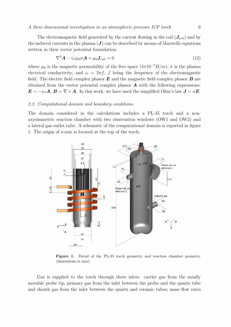
The domain considered in the calculations includes a PL-35 torch and a non-
axysimmetric reaction chamber with two observation windows (OW1 and OW2) and
a lateral gas outlet tube. A schematic of the computational domain is reported in figure
1. The origin of z-axis is located at the top of the torch.
Figure 1. Detail of the PL-35 torch geometry and reaction chamber geometry(dimensions in mm).
Gas is supplied to the torch through three inlets: carrier gas from the axially
movable probe tip, primary gas from the inlet between the probe and the quartz tube
and sheath gas from the inlet between the quartz and ceramic tubes; mass flow rates
A three-dimensional investigation in an atmospheric-pressure ICP torch 7
are 2.5 slpm of Ar, 15 slpm of Ar and 60 slpm of Ar + 4.5 slpm of H2 for carrier gas,
central gas and sheath gas, respectively. A no-slip boundary condition is assumed on
internal walls.
In order to reduce the total number of cells in the computation grid, the inlet
regions of the primary and secondary gas (8 separate injection points for the tangential
injection of the primary gas and 18 points for the axial injection of the secondary gas)
have been idealized with two annular inlets with uniform gas injection, since it has been
shown that results are only slightly sensible to this simplification [11].
The equation of energy has been solved including in the domain the solid regions
inside the quartz and ceramic tubes, whereas the EM field has been computed using
the extended field approach [34], thus solving the EM equations in a cylindrical domain
around the torch (150 mm diameter, 113 mm height) with vanishing vector potential on
its surface. A fixed temperature (300 K) has been imposed at the internal walls of the
chamber and at the external walls of the torch. The torch and the reaction chamber
operate at atmospheric pressure.
2.3. Plasma properties
Plasma thermodynamic and transport properties have been computed using 4th order
Chapman-Enskog method, including Ar, Ar+, H2, H, H+ and electrons in the
computation of composition [35]. Combined diffusion coefficients have been computed
following Murphy [6]. In order to carry out the computation of equilibrium composition,
data for partition function calculations have been obtained from JANAF tables [36] and
NIST database [37]. Each iteration, plasma properties have been updated on the basis
of the local temperature and local mass fraction of hydrogen in the mixture.
Radiation losses have been taken in account using data reported by Beulens et al
[38] for atmospheric pressure plasmas. Radiation losses due to the presence of hydrogen
have been neglected because, to the knowledge of the authors, no reliable radiation
power data are available for argon-hydrogen mixtures and radiative emission due to
hydrogen is substantially lower than that of argon [39]; moreover, in these simulations,
hydrogen contribution to radiation can be reasonably neglected owing to small mass
fraction of this gas (maximum YH = 0.0045).
3. Results and discussion
Computations have been carried out for a plasma source operating at 3 MHz (case C1)
and for the same system with coil current frequency set to 13.56 MHz (case C2). In both
cases, the current intensity has been adjusted to make the total Joule power dissipated
in the plasma discharge equal to 15 kW: in case C1 the current is 210 A whereas in case
C2, as a result of the higher frequency, its value must be set at 117 A.

A three-dimensional investigation in an atmospheric-pressure ICP torch 8
3.1. Three-dimensional effects on temperature and velocity fields inside the torch
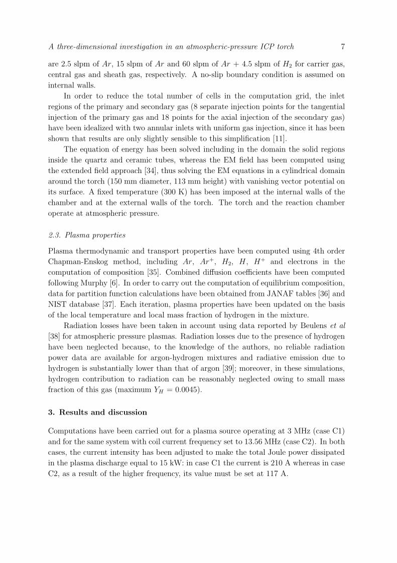
In figure 2 the temperature field on two orthogonal planes passing through the axis
of the torch for case C1 and C2 is reported. The maximum temperature for case C1
(11713 K) is located approximately at the same axial position of the probe tip (z = 60
mm), whereas for case C2 the maximum temperature (11606 K) is reached at z = 49
mm; in both cases, owing to the shielding effect of the induced currents, the maximum
temperature is located at an off-axis position (r = 9 mm and r = 10 mm for case C1
and C2, respectively). As shown in the x-y cross sections reported in figures 2-c and 2-f,
at the torch outlet the distribution of temperature is strongly deviated in the positive
y-direction for the case at 3 MHz, whereas it is almost axisymmetric for the case with
13.56 MHz. As can be seen from temperature distributions reported on the cross sections
at 58 mm and 85 mm, the non-axisymmentry for the case C1 is lower in the mid-coil
region of the torch than at the outlet, whereas for case C2 it is more pronounced at z
= 58 mm.
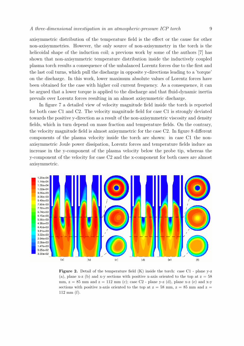
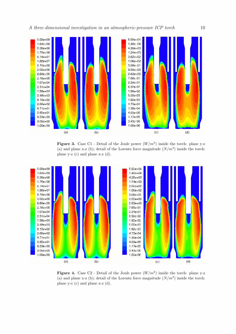
Logarithmic contours of Joule dissipation and Lorentz forces for case C1 and C2 are
reported in figures 3 and 4, respectively; according to previous works on simulation of
ICP torches with various frequencies imposed to the coil current [15, 40, 41], the Joule
dissipation inside the torch for case C1 is concentrated in a larger region than for case
C2, as a result of a bigger skin depth. A similar distribution is obtained for Lorentz
forces (figures 3-c, 3-d, 4-c and 4-d), because both Joule dissipation and Lorentz forces
arise in the regions characterized by higher plasma conductivity.
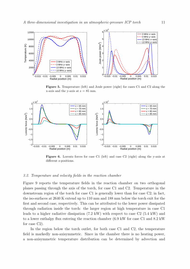
Temperature and Joule power distributions along the x and y axis for case C1
and C2 at z = 85 mm are reported in figure 5. A non-axisymmetry is present for
the temperature distribution along the y-axis for the case at 3 MHz (C1), whereas
for the case C2 the temperature profiles along x-axis and y-axis are similar and almost
axisymmetric. For the case at 3 MHz the Joule power has a peak at r = 0.01 m and high
values (order of magnitude = 108 W/m3) are present also inside the hot region of the
discharge, whereas for the case at 13.56 MHz the peaks are located at r = 0.013 m but
with a strong decrease of Joule power in the central portion of the torch and negligible
values for r < 0.005 m. A strong non-axisymmetry in Joule power distribution is present
for both cases along the y-axis; for case C2 it is located at radial coordinate greater than
0.01 m, whereas for the case at 3 MHz the non-axisymmetry is pronounced also inside
the discharge.
Since non-axisymmetries in temperature and Joule distributions are mainly located
along the y-axis direction, in figure 6 a detail of the Lorentz force field along y-axis at
different z-axis position for case C1 and C2 are reported: the higher value of the skin
depth in case C1 leads to a larger region with high values (order of magnitude = 104
N/m3) of Lorentz forces (0.005 < r < 0.015 m for case C1, 0.009 < r < 0.015 for case
C2).
Since Joule power distribution, Lorentz forces and temperature field are coupled
by means of the electrical conductivity field, it is difficult to state whether the non-
A three-dimensional investigation in an atmospheric-pressure ICP torch 9
axisymmetric distribution of the temperature field is the effect or the cause for other
non-axisymmetries. However, the only source of non-axisymmetry in the torch is the
helicoidal shape of the induction coil; a previous work by some of the authors [7] has
shown that non-axisymmetric temperature distribution inside the inductively coupled
plasma torch results a consequence of the unbalanced Lorentz forces due to the first and
the last coil turns, which pull the discharge in opposite y-directions leading to a ’torque’
on the discharge. In this work, lower maximum absolute values of Lorentz forces have
been obtained for the case with higher coil current frequency. As a consequence, it can
be argued that a lower torque is applied to the discharge and that fluid-dynamic inertia
prevails over Lorentz forces resulting in an almost axisymmetric discharge.
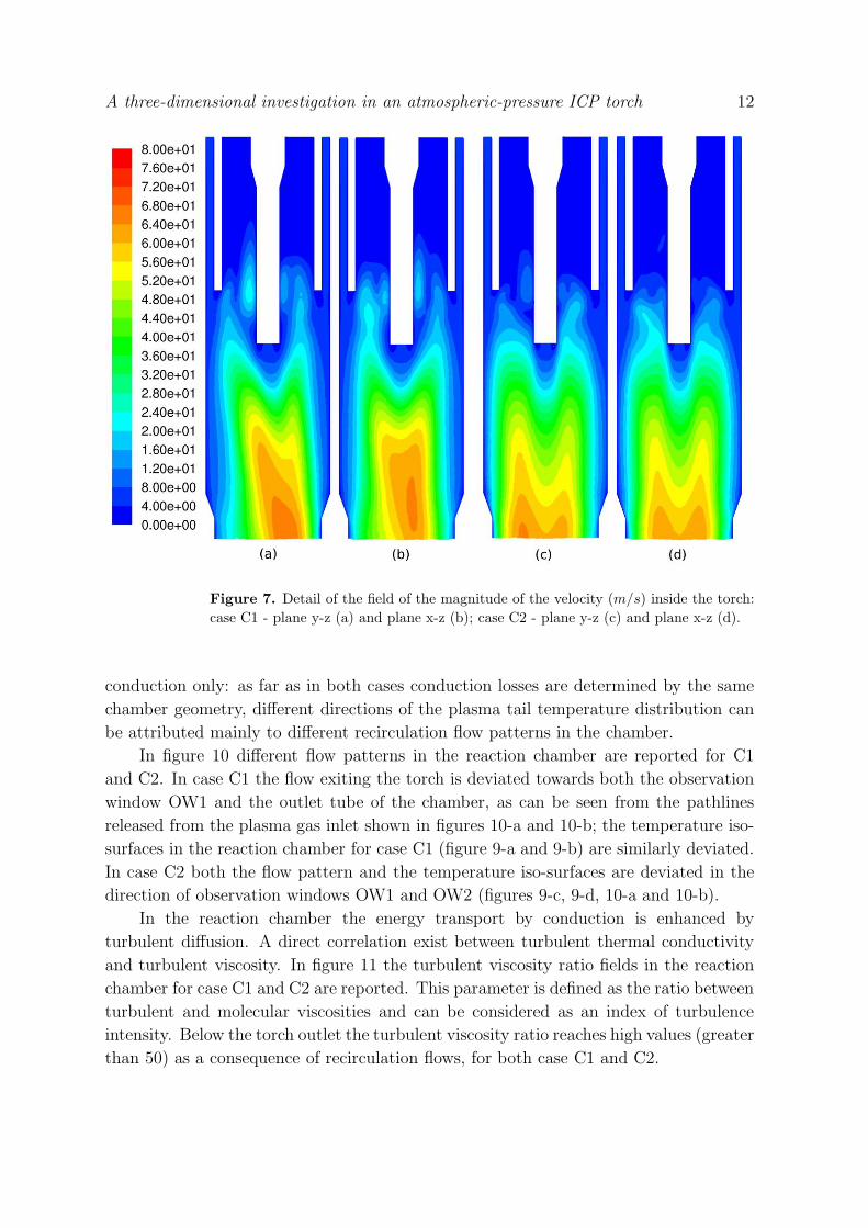
In figure 7 a detailed view of velocity magnitude field inside the torch is reported
for both case C1 and C2. The velocity magnitude field for case C1 is strongly deviated
towards the positive y-direction as a result of the non-axisymmetric viscosity and density
fields, which in turn depend on mass fraction and temperature fields. On the contrary,
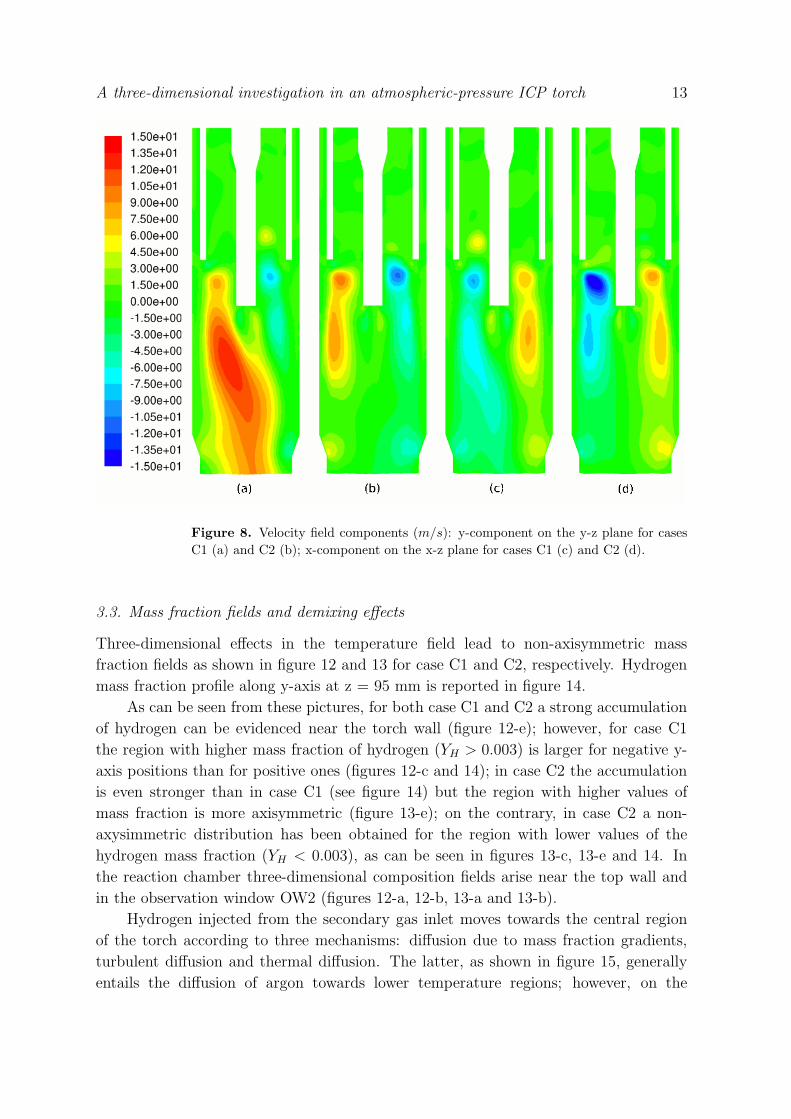
the velocity magnitude field is almost axisymmetric for the case C2. In figure 8 different
components of the plasma velocity inside the torch are shown: in case C1 the non-
axisymmetric Joule power dissipation, Lorentz forces and temperature fields induce an
increase in the y-component of the plasma velocity below the probe tip, whereas the
y-component of the velocity for case C2 and the x-component for both cases are almost
axisymmetric.
Figure 2. Detail of the temperature field (K) inside the torch: case C1 - plane y-z(a), plane x-z (b) and x-y sections with positive x-axis oriented to the top at z = 58mm, z = 85 mm and z = 112 mm (c); case C2 - plane y-z (d), plane x-z (e) and x-ysections with positive x-axis oriented to the top at z = 58 mm, z = 85 mm and z =112 mm (f).
A three-dimensional investigation in an atmospheric-pressure ICP torch 10
Figure 3. Case C1 - Detail of the Joule power (W/m3) inside the torch: plane y-z(a) and plane x-z (b); detail of the Lorentz force magnitude (N/m3) inside the torch:plane y-z (c) and plane x-z (d).
Figure 4. Case C2 - Detail of the Joule power (W/m3) inside the torch: plane y-z(a) and plane x-z (b); detail of the Lorentz force magnitude (N/m3) inside the torch:plane y-z (c) and plane x-z (d).
A three-dimensional investigation in an atmospheric-pressure ICP torch 11
−0.015 −0.01 −0.005 0 0.005 0.01 0.0150
2000
4000
6000
8000
10000
12000
Radial position (m)
Tem
pera
ture
(K)
3 MHz x−axis3 MHz y−axis13 MHz x−axis13 MHz y−axis
−0.015 −0.01 −0.005 0 0.005 0.01 0.0150
1
2
3
4
5
6x 10
8
Radial position (m)
Joul
epo
wer
(W/m
3 )
3 MHz x−axis3 MHz y−axis13 MHz x−axis13 MHz y−axis
Figure 5. Temperature (left) and Joule power (right) for cases C1 and C2 along thex-axis and the y-axis at z = 85 mm.
−0.015 −0.01 −0.005 0 0.005 0.01 0.015−2
−1.5
−1
−0.5
0
0.5
1
1.5
2x 10
4
Radial position (m)
Lore
ntz
forc
e(N
/m3 )
z = 65 mmz = 70 mmz = 80 mmz = 85 mm
−0.015 −0.01 −0.005 0 0.005 0.01 0.015−2
−1.5
−1
−0.5
0
0.5
1
1.5
2x 10
4
Radial position (m)
Lore
ntz
forc
e(N
/m3 )
z = 65 mmz = 70 mmz = 80 mmz = 85 mm
Figure 6. Lorentz forces for case C1 (left) and case C2 (right) along the y-axis atdifferent z-positions.
3.2. Temperature and velocity fields in the reaction chamber
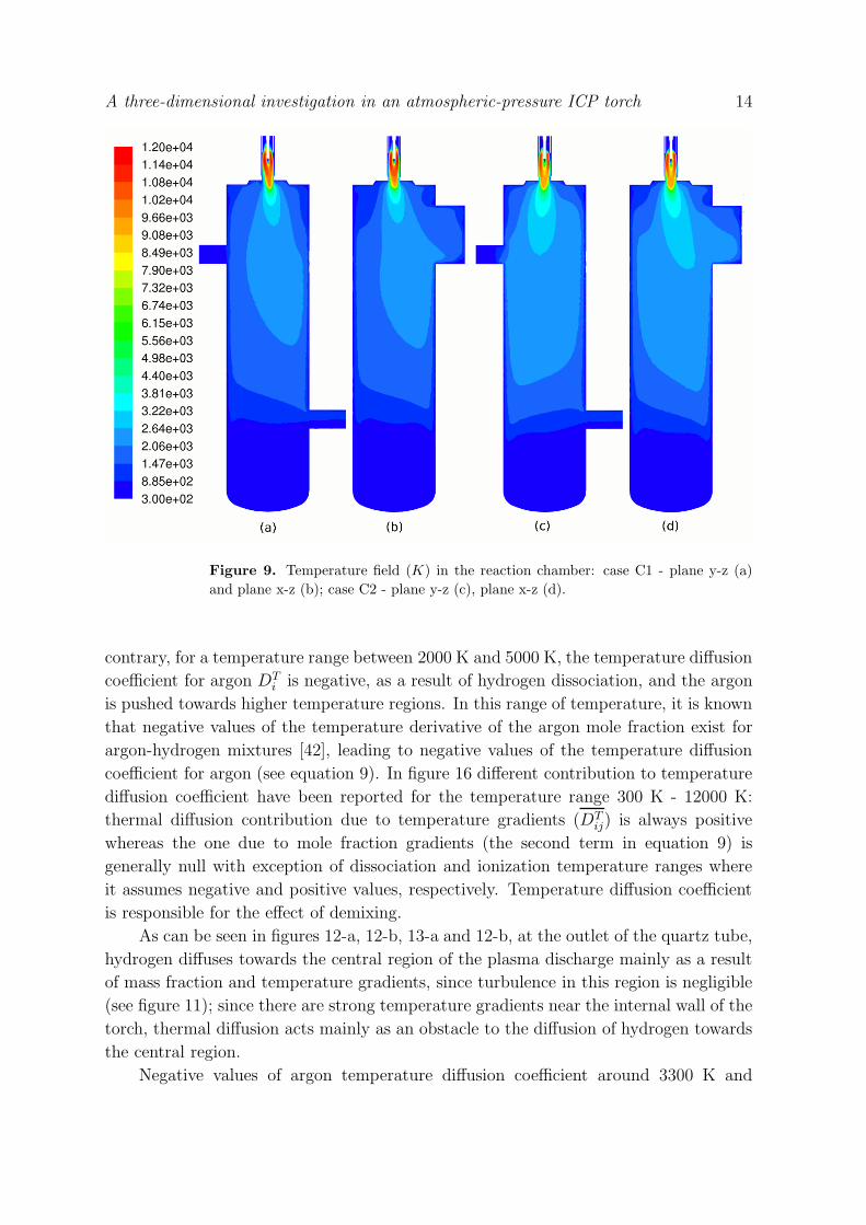
Figure 9 reports the temperature fields in the reaction chamber on two orthogonal
planes passing through the axis of the torch, for case C1 and C2. Temperature in the
downstream region of the torch for case C1 is generally lower than for case C2; in fact,
the iso-surfaces at 2640 K extend up to 110 mm and 188 mm below the torch exit for the
first and second case, respectively. This can be attributed to the lower power dissipated
through radiation inside the torch: the larger region at high temperature in case C1
leads to a higher radiative dissipation (7.2 kW) with respect to case C2 (5.4 kW) and
to a lower enthalpy flux entering the reaction chamber (6.9 kW for case C1 and 8.2 kW
for case C2).
In the region below the torch outlet, for both case C1 and C2, the temperature
field is markedly non-axisymmetric. Since in the chamber there is no heating power,
a non-axisymmetric temperature distribution can be determined by advection and
A three-dimensional investigation in an atmospheric-pressure ICP torch 12
Figure 7. Detail of the field of the magnitude of the velocity (m/s) inside the torch:case C1 - plane y-z (a) and plane x-z (b); case C2 - plane y-z (c) and plane x-z (d).
conduction only: as far as in both cases conduction losses are determined by the same
chamber geometry, different directions of the plasma tail temperature distribution can
be attributed mainly to different recirculation flow patterns in the chamber.
In figure 10 different flow patterns in the reaction chamber are reported for C1
and C2. In case C1 the flow exiting the torch is deviated towards both the observation
window OW1 and the outlet tube of the chamber, as can be seen from the pathlines
released from the plasma gas inlet shown in figures 10-a and 10-b; the temperature iso-
surfaces in the reaction chamber for case C1 (figure 9-a and 9-b) are similarly deviated.
In case C2 both the flow pattern and the temperature iso-surfaces are deviated in the
direction of observation windows OW1 and OW2 (figures 9-c, 9-d, 10-a and 10-b).
In the reaction chamber the energy transport by conduction is enhanced by
turbulent diffusion. A direct correlation exist between turbulent thermal conductivity
and turbulent viscosity. In figure 11 the turbulent viscosity ratio fields in the reaction
chamber for case C1 and C2 are reported. This parameter is defined as the ratio between
turbulent and molecular viscosities and can be considered as an index of turbulence
intensity. Below the torch outlet the turbulent viscosity ratio reaches high values (greater
than 50) as a consequence of recirculation flows, for both case C1 and C2.
A three-dimensional investigation in an atmospheric-pressure ICP torch 13
Figure 8. Velocity field components (m/s): y-component on the y-z plane for casesC1 (a) and C2 (b); x-component on the x-z plane for cases C1 (c) and C2 (d).
3.3. Mass fraction fields and demixing effects
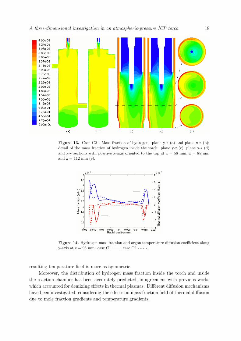
Three-dimensional effects in the temperature field lead to non-axisymmetric mass
fraction fields as shown in figure 12 and 13 for case C1 and C2, respectively. Hydrogen
mass fraction profile along y-axis at z = 95 mm is reported in figure 14.
As can be seen from these pictures, for both case C1 and C2 a strong accumulation
of hydrogen can be evidenced near the torch wall (figure 12-e); however, for case C1
the region with higher mass fraction of hydrogen (YH > 0.003) is larger for negative y-
axis positions than for positive ones (figures 12-c and 14); in case C2 the accumulation
is even stronger than in case C1 (see figure 14) but the region with higher values of
mass fraction is more axisymmetric (figure 13-e); on the contrary, in case C2 a non-
axysimmetric distribution has been obtained for the region with lower values of the
hydrogen mass fraction (YH < 0.003), as can be seen in figures 13-c, 13-e and 14. In
the reaction chamber three-dimensional composition fields arise near the top wall and
in the observation window OW2 (figures 12-a, 12-b, 13-a and 13-b).
Hydrogen injected from the secondary gas inlet moves towards the central region
of the torch according to three mechanisms: diffusion due to mass fraction gradients,
turbulent diffusion and thermal diffusion. The latter, as shown in figure 15, generally
entails the diffusion of argon towards lower temperature regions; however, on the
A three-dimensional investigation in an atmospheric-pressure ICP torch 14
Figure 9. Temperature field (K) in the reaction chamber: case C1 - plane y-z (a)and plane x-z (b); case C2 - plane y-z (c), plane x-z (d).
contrary, for a temperature range between 2000 K and 5000 K, the temperature diffusion
coefficient for argon DTi is negative, as a result of hydrogen dissociation, and the argon
is pushed towards higher temperature regions. In this range of temperature, it is known
that negative values of the temperature derivative of the argon mole fraction exist for
argon-hydrogen mixtures [42], leading to negative values of the temperature diffusion
coefficient for argon (see equation 9). In figure 16 different contribution to temperature
diffusion coefficient have been reported for the temperature range 300 K - 12000 K:
thermal diffusion contribution due to temperature gradients (DTij) is always positive
whereas the one due to mole fraction gradients (the second term in equation 9) is
generally null with exception of dissociation and ionization temperature ranges where
it assumes negative and positive values, respectively. Temperature diffusion coefficient
is responsible for the effect of demixing.
As can be seen in figures 12-a, 12-b, 13-a and 12-b, at the outlet of the quartz tube,
hydrogen diffuses towards the central region of the plasma discharge mainly as a result
of mass fraction and temperature gradients, since turbulence in this region is negligible
(see figure 11); since there are strong temperature gradients near the internal wall of the
torch, thermal diffusion acts mainly as an obstacle to the diffusion of hydrogen towards
the central region.
Negative values of argon temperature diffusion coefficient around 3300 K and

A three-dimensional investigation in an atmospheric-pressure ICP torch 15
Figure 10. Pathlines released from plasma gas inlet: case C1 - y-z view (a), x-z view(b); case C2 - y-z view (c), x-z view (d).
positive values for lower temperature result in an accumulation of hydrogen in the
temperature region where the coefficient is null (T = 2000 K). In fact, hydrogen mass
fraction has its maximum value (YH = 0.0045) in the fringes of the discharge and this is
greater than the mass fraction of hydrogen in the inlet sheath gas (YH at inlet = 0.00374).
In figure 14 hydrogen mass fraction and argon temperature diffusion coefficient along
the y-axis at z = 85 mm have been reported: peaks in hydrogen mass fraction are
strongly correlated with negative peaks in argon temperature diffusion coefficients and
they are located where temperature is about 2000 K, i.e. the just below the dissociation
temperature range.
As can be seen in figure 15, for temperature higher than 4500 K the argon
temperature diffusion coefficient is positive. The point of transition between negative
and positive values is a dispersion point for hydrogen: in presence of a temperature
gradient, hydrogen at temperature lower than the transition temperature is pushed
towards lower temperature zones whereas hydrogen at temperature higher than the
transition temperature is pushed towards higher temperature ones; this results in a
hydrogen dispersion towards lower or higher temperatures. This is clear from figure 14
where mass fraction of hydrogen has been plotted: for case C1 a local minima which
correspond to dispersion points are found at y = -0.011 m and y = 0.013 m whereas for
case C2 they are located at y = -0.015 m and y = 0.012 m.
Similar results have been obtained also by Chen for a different ICP torch

A three-dimensional investigation in an atmospheric-pressure ICP torch 16
Figure 11. Turbulent viscosity ratio: case C1 - plane y-z (a) and plane x-z (b); caseC2 - plane y-z (c) and plane x-z (d).
configuration [28] and the accumulation of hydrogen in the cold boundary layer of
a thermal spray torch was simulated by Ghorui et al [43] using a two-temperature
combined diffusion approach. These results are in agreement also with previous
investigations by Murphy [42] in which a peak of hydrogen mass fraction has been
predicted in the low-temperature fringes of a free burning arc.
In the reaction chamber, hydrogen diffusion is dominated by turbulence: the
viscosity ratio reaches values of the order of 50 where the gas expands in the reaction
chamber, as shown in figure 11, and the hydrogen is almost completely mixed (figures
12-a, 12-b, 13-a and 13-b). In the fringes of the plasma plume in the reaction chamber,
where temperature is below the dissociation range, thermal diffusion pushes hydrogen
(almost completely in its molecular form) towards higher temperature regions.
In figure 17 the mass fraction of hydrogen is reported for a fictitious case where
thermal diffusion due to temperature gradients has been neglected. The temperature
coefficient used has been plotted in figure 16 for YH = 0.002. For both cases C1
and C2, the mass fraction in the chamber is almost constant, as a result of null
temperature diffusion coefficient below the dissociation temperature range. In the torch,
the accumulation of hydrogen in the fringes of the discharge is enhanced, since the
positive contribution to the temperature coefficient due to temperature gradients has
been neglected. Thus, according to previous investigations by Murphy on free-burning
arcs [42], the accumulation of hydrogen in the fringes of the discharge can be attributed

A three-dimensional investigation in an atmospheric-pressure ICP torch 17
mainly to diffusion due to mole fraction gradients.
Figure 12. Case C1 - Mass fraction of hydrogen: plane y-z (a) and plane x-z (b);detail of the mass fraction of hydrogen inside the torch: plane y-z (c), plane x-z (d)and x-y sections with positive x-axis oriented to the top at z = 58 mm, z = 85 mmand z = 112 mm (e).
4. Conclusions
A fully three-dimensional model of a commercial ICP torch with laboratory scale
reaction chamber has been developed using a commercial CFD software (FLUENT c©).
Numerical results, which completely characterize the electromagnetic and thermo-fluid-
dynamic behavior of the system, are presented for an atmospheric pressure argon-
hydrogen mixture using the RNG k-ε turbulence model and the combined diffusion
approach of Murphy. Two different cases have been considered with different coil current
frequency (3 MHz and 13.56 MHz), the other operating conditions being fixed (mass ow
rates, total Joule power dissipated, inlet gas composition).
This approach has allowed a deeper insight in the three-dimensional effects of the
coil current frequency: non-axisimmetrical velocity, temperature, Joule dissipation and
Lorentz force fields have been found for current frequency equal to 3 MHz, whereas
for the case at higher frequency the discharge in the torch is almost axisymmetric. At
higher frequency, the lower absolute value of Lorentz forces and the smaller volume
of the discharge where they are applied, induces a lower unbalance between the force
exerted on the discharge by the first and the last coil turn; thus, it is argued that fluid-
dynamic inertia prevails over the torque applied to the discharge by the coil and the
A three-dimensional investigation in an atmospheric-pressure ICP torch 18
Figure 13. Case C2 - Mass fraction of hydrogen: plane y-z (a) and plane x-z (b);detail of the mass fraction of hydrogen inside the torch: plane y-z (c), plane x-z (d)and x-y sections with positive x-axis oriented to the top at z = 58 mm, z = 85 mmand z = 112 mm (e).
Figure 14. Hydrogen mass fraction and argon temperature diffusion coefficient alongy-axis at z = 95 mm: case C1 ——, case C2 - - - -.
resulting temperature field is more axisymmetric.
Moreover, the distribution of hydrogen mass fraction inside the torch and inside
the reaction chamber has been accurately predicted, in agreement with previous works
which accounted for demixing effects in thermal plasmas. Different diffusion mechanisms
have been investigated, considering the effects on mass fraction field of thermal diffusion
due to mole fraction gradients and temperature gradients.

A three-dimensional investigation in an atmospheric-pressure ICP torch 19
0 2000 4000 6000 8000 10000 12000−1.5
−1
−0.5
0
0.5
1
1.5
2
2.5
3x 10
−5
Temperature (K)
Tem
pera
ture
diffu
sion
coef
ficie
nt(k
g/m
s)
YH
= 0
YH
= 0.002
YH
= 0.004
YH
= 0.006
YH
= 0.008
YH
= 0.01
Figure 15. Argon temperature diffusion coefficients (DTAr) as a function of
temperature for argon-hydrogen mixtures, for constant mass fractions of hydrogen.
0 2000 4000 6000 8000 10000 12000−4
−2
0
2
4
6
8
10x 10
−6
Temperature (K)
Tem
pera
ture
diffu
sion
coef
ficie
nt(k
g/m
s)
Total thermal diffusionThermal diffusion due to mole fraction gradientsThermal diffusion due to temperature gradients
Figure 16. Different contributions to argon temperature diffusion coefficient (DTAr)
as a function of temperature for argon-hydrogen mixtures, for constant mass fractionof hydrogen (YH = 0.002).
Finally, the temperature field in the reaction chamber has been simulated: its three-
dimensional shape has been correlated to different types of recirculation flow arising
when a non-axisymmetric reaction chamber, which include a lateral outlet tube, is used.
Accurate modeling of devices characterized by inherently non-axisymmetric
geometries such as inductively coupled plasma torches, requires the implementation
of three-dimensional codes to analyze the magnitude of non-axisymmetric effects on
plasma properties arising under different operating conditions. This is true in particular
for the modeling of powder treatment processes such as powder spheroidization and
nano-particles production, since the behavior of injected raw materials and of nucleated
aerosols in the reaction chamber depends strongly on temperature and velocity fields.

A three-dimensional investigation in an atmospheric-pressure ICP torch 20
Figure 17. Mass fraction of hydrogen on plane y-z neglecting thermal diffusion dueto temperature gradients: case C1 - chamber view (a) and torch view (b); case C2 -chamber view (c) and torch view (d).
References
[1] Boulos M I 1997 High Temp. Mater. Process. 1 17-39[2] Murphy A B, Boulos M I, Colombo V, Fauchais P, Ghedini E, Gleizes A, Mostaghimi J, Proulx P
and Schram D C 2008 High Temperature Material Processes 12 255-336[3] Colombo V, Ghedini E and Mostaghimi J 2008 IEEE Trans. Plasma Sci. 36 1040-1[4] Ye R, Ishigaki T, Taguchi H, Ito S, Murphy A B and Lange H 2006 J. Appl. Phys. 100 103303[5] Murphy A B 1993 Phys. Rev. E 48 3594[6] Murphy A B 2001 J. Phys. D: Appl. Phys. 34 R151[7] Bernardi D, Colombo V, Ghedini E and Mentrelli A 2003 Eur. J. Phys. D 22 119-25[8] Bernardi D, Colombo V, Ghedini E and Mentrelli A 2003 Eur. J. Phys. D 25 279-85[9] Bernardi D, Colombo V, Ghedini E, Mentrelli A and Trombetti T 2004 Eur. J. Phys. D 28 423-33
[10] Bernardi D, Colombo V, Ghedini E, Mentrelli A and Trombetti T 2005 IEEE Trans. Plasma Sci.33 424-5
[11] Colombo V and Ghedini E 2007 High Temperature Material Processes 11 283-96[12] Njah Z, Mostaghimi J and Boulos M I 1993 Int. J. Heat Mass Transfer 36 3909-19[13] Njah Z, Mostaghimi J, Faghri M and Boulos M I 1993 Int. J. Heat Mass Transfer 36 3897-907[14] Siegmann St, Leparoux M, Schreuders C, Shin J W and Rohr L 2005 Proceedings of 17th
International Symposium on Plasma Chemistry (ISPC 17) Toronto, Ontario, Canada[15] Bernardi D, Colombo V, Ghedini E and Mentrelli A 2003 Eur. J. Phys. D 25 271-7[16] Bernardi D, Colombo V, Ghedini E and Mentrelli A 2005 Pure Appl. Chem. 77 359-72[17] Karoly Z and Szepvolgyi J 2003 Powder Technology 132 211-15[18] Shin J W, Miyazoe H, Leparoux M, Siegmann St, Dorier J L and Hollenstein Ch 2006 Plasma
Sources Sci. Technol. 15 441-9

A three-dimensional investigation in an atmospheric-pressure ICP torch 21
[19] Fan X, Gitzhofer E and Boulos M I 1998 J. Therm. Spray Technol. 7 247-53[20] Ye R, Ishigaki T, Jurewicz J, Proulx P and Boulos M I 2004 Plasma Chem. Plasma Process. 24
555-71[21] Ramshaw J D and Chang C H 1996 Phys. Rev E 53 6382-8[22] Tanaka Y 2002 J. Phys. D: Appl. Phys. 35 468-76[23] Tanaka Y 2004 J. Phys. D: Appl. Phys. 37 1190-205[24] Watanabe T and Sugimoto N 2004 Thin Solid Films 457 201-8[25] Atsuchi N, Shigeta M and Watanabe T 2006 Int. J. Heat Mass Transfer 49 1073-82[26] Watanabe T, Shigeta M and Atsuchi N 2006 Int. J. Heat Mass Transfer 49 4867-76[27] Xue S, Proulx P, Murphy A B and Boulos M I 2005 Proc. 17th International Symposium on Plasma
Chemistry, Toronto, Canada[28] Chen X, Sugasawa M and Kikukawa N 1998 J. Phys. D: Appl. Phys. 31 1187-96[29] Siegmann S, Girshick S L, Szepvolgyi J, Leparoux M, Shin J W, Schreuders C, Rohr L, Ishigaki
T, Jurewicz J W, Habib M, Baroud G, Gitzhofer F, Kambara M, Diaz J M A, Yoshida T 2008High Temperature Material Processes 12 205-54
[30] Xue S, Proulx P and Boulos M I 2003 Proc. 16th International Symposium on Plasma Chemistry,Taormina, Italy
[31] Ye R, Murphy A B and Ishigaki T 2007 Plasma Chem. Plasma Process. 27 189-204[32] Rini P, Vanden Abeele D and Degrez G 2006, J. Thermophys. Heat Trans. 20 31-40[33] FLUENT 6.3 User’s Guide 2006, Fluent Inc. Centerra Resource Park 10 Cavendish Court, Lebanon,
NH 03766[34] Bernardi D, Colombo V, Ghedini E and Mentrelli A 2003 Eur. J. Phys. D 27 55-72[35] Colombo V, Ghedini E and Sanibondi P 2009 J. Phys. D: Appl. Phys. 42 055213 (12pp)[36] Chase M W, Davies C A, Downey J R, Frurip D J, McDonald R A and Syverud A N 1985 JANAF
Thermochemical Tables 3rd ed. J. Phys. Chem. Ref. Data 14[37] Ralchenko Y, Kramida A E, Reader J and NIST ASD Team 2008 NIST Atomic Spectra Database
(version 3.1.5), [Online]. Available: http://physics.nist.gov/PhysRefData/ASD/index.html.National Institute of Standards and Technology, Gaithersburg, MD.
[38] Beulens J J, Milojevic D, Schram D C and Vallinga P M 1991 Phys. Fluids B 3 254857[39] Essoltani A, Proulx P, Boulos M I and Gleizes A 1995 Plasma Chem. Plasma Process. 14 301-15[40] Shigeta M, Sato T and Nishiyama H 2004 Int. J. Heat Mass Transfer 47 70716[41] Bolot R, Coddet C, Schreuders C, Leparoux M and Siegmann S 2007 Journal of Thermal Spray
Technology 16 690-7[42] Murphy A B 1997 Phys. Rev. E 55 7473-94[43] Ghorui S, Vysohlid M, Heberlein J V R and Pfender E 2007 Phys. Rev. E 76 016404