A Testbed for research and development of SDN applications ... · A Testbed for research and...
63
A Testbed for research and development of SDN applications using OpenFlow Nádia Pires Gonçalves Thesis to obtain the Master of Science Degree in Telecommunications and Informatics Engineering Supervisor: Prof. Fernando Henrique Côrte-Real Mira da Silva Examination Committee Chairperson: Prof. Paulo Jorge Pires Ferreira Supervisor: Prof. Fernando Henrique Côrte-Real Mira da Silva Member of the Committee: Prof. Rui Jorge Morais Tomaz Valadas June 2014
Transcript of A Testbed for research and development of SDN applications ... · A Testbed for research and...

A Testbed for research and development of SDN applicationsusing OpenFlow
Nádia Pires Gonçalves
Thesis to obtain the Master of Science Degree in
Telecommunications and Informatics Engineering
Supervisor: Prof. Fernando Henrique Côrte-Real Mira da Silva
Examination Committee
Chairperson: Prof. Paulo Jorge Pires FerreiraSupervisor: Prof. Fernando Henrique Côrte-Real Mira da Silva
Member of the Committee: Prof. Rui Jorge Morais Tomaz Valadas
June 2014

ii

Acknowledgments
A vida pos no meu caminho a possibilidade de terminar uma das grandes fases da minha vida, o
Mestrado em Engenharia de Telecomunicacoes e Informatica.
Em primeiro lugar quero agradecer ao IST por me pemitir fazer o Mestrado, numa que e das maiores
Universidades de Portugal. Agradeco ao meu orientador, Fernando Mira da Silva, pelo o apoio e a
compreensao que teve comigo, quero agradecer ao juri pela sua disponibilidade.
Em segundo lugar, quero agradecer a minha famılia por todos os sacrıficios que passaram para me
dar a educacao que tenho hoje. Em particular, quero agradecer ao meu pai pelo o HOMEM que e, pelo
o apoio que me deu e por aceitar principalmente as minhas decisoes; a minha mae por ser uma grande
MULHER, pelo o apoio incondicional e por acreditar em mim mesmo quando eu nao acreditava; ao meu
irmao pelas diversas picardias que tinhamos e por estar sempre presente e por ultimo a minha afilhada
que foi uma fonte motivadora.
Nao posso me esquecer de agradecer aos meus ”segundos pais”, a Sra Etelvina Pereira e ao Sr.
Gabriel Pereira, por me apoiarem, por me acolherem, por disponibilizarem tempo para me ajudar e por
me levantarem a moral quando estava em baixo. Agradeco mesmo a dedicacao que tiveram por mim.
Nao posso deixar de agradecer a duas pessoas que sao muito especiais para mim. Agradeco ao
Luıs Goncalves, pela motivacao que tinha quando eu falava da minha tese, pela ajuda em rever comigo
o conteudo da tese e pelo amigo que e. E proibido nao agradecer ao Goncalo Pereira, pelo o esforco
que fez, pelo o optimo saco de box, pelo o apoio, pela paciencia, por tudo mesmo. Ao Goncalo eu
devo-lhe tudo e o agradecimento nao e suficiente. Obrigada Goncalo, por me tornares uma melhor
pessoa e por seres meu amigo.
Por ultimo mas nao menos importante, ao meus amigos de faculdade; Vitor Mansur, Jerome Figueiredo,
Dinamene Barreira, Andre Camoes, Carlos Simoes, Joao Rosa, Andreia Soares e Joao Gomes, pelo
o supote e por me terem acompanhado. As minhas amigas de apartamento, Luısa Neves, Rita Gar-
cia Marques e Silvia Centeio pela motivacao, pelas horas de seca por estar a falar sobre a tese, pela
diversao e pelo o acompanhamento e por fim a Graciela Torres, a Helena Ferreira e ao Duarte Martins
por me acompanharem e apoiarem neste percurso de vida.
iii

Abstract
Network technologies have been dominated by traditional paradigms resulting from the Transmission
Control Protocol (TCP)/Internet Protocol (IP) model and local networks, centered on traditional switching
and routing concepts. The current network complexity at the data center, local and operator levels
present new management challenges and flexibility requirements. The Software-Defined Networking
(SDN) paradigm emerged to tackle these challenges. The main goal of SDN is to separate the control
plane from the data plane, which are usually tied together in conventional network devices, in such way
that these can be managed, controlled and monitored by custom applications, enabling increased net-
work flexibility independently of proprietary solutions. OpenFlow is a communication protocol based on
the SDN paradigm, which defines a communication between the data plane and the control plane. This
project aims to create a testbed in order to facilitate the comprehension about Programmable Network.
Keywords: Software-Defined Networking, OpenFlow, POX
iv

Resumo
Tecnologias de redes tem sido denominadas pelo paradigma tradicional resultando no modelo TCP/IP
e na rede local, centradas num tradicional switching e conceitos de routing. A rede local e complexa
a nıvel dos centros de dados, a nıvel local e a nıvel de operadores presentes na gestao do desafio e
da flexibilidade de requisitos. O paradigma de SDN emerge para enfrentar esse desafio. O principal
objetivo do SDN e separar o plano de controlo do plano de dados, que sao usualmente amarrados pelos
os dispositivos de rede convencional, numa certa forma que estes podem ser geridos, controlados
e monitorizados pela aplicacao, garantindo aumentar a flexibilidade da rede independentemente de
solucoes proprietarias. OpenFlow e um protocolo de comunicacao baseado no paradigma de SDN, no
qual define uma comunicacao entre o plano de dados e o plano de controlo. Este projeto tem como
objetivo criar uma testbed em ordem a facilitar a compreensao acerca das redes programaveis.
Palavras-chave: Software-Defined Networking, OpenFlow, POX
v

Contents
Acknowledgments iii
Abstract iv
Resumo v
List of Figures viii
List of Tables ix
Acronyms ix
1 Introduction 2
1.1 Objectives and Contributions . . . . . . . . . . . . . . . . . . . . . . . . . . . . . . . . . . 3
1.2 Dissertation Structure . . . . . . . . . . . . . . . . . . . . . . . . . . . . . . . . . . . . . . 3
2 State-of-the-Art 5
2.1 Limitations of conventional networking technologies . . . . . . . . . . . . . . . . . . . . . 5
2.2 Architecture of Software-Defined Networking . . . . . . . . . . . . . . . . . . . . . . . . . 6
2.3 OpenFlow Protocol . . . . . . . . . . . . . . . . . . . . . . . . . . . . . . . . . . . . . . . . 7
2.3.1 OpenFlow Architecture . . . . . . . . . . . . . . . . . . . . . . . . . . . . . . . . . 8
2.3.2 Simulators . . . . . . . . . . . . . . . . . . . . . . . . . . . . . . . . . . . . . . . . 16
2.3.3 Features and Limitations of OpenFlow . . . . . . . . . . . . . . . . . . . . . . . . . 16
2.4 Graphical Interface for Controllers . . . . . . . . . . . . . . . . . . . . . . . . . . . . . . . 17
2.5 Applications of SDN . . . . . . . . . . . . . . . . . . . . . . . . . . . . . . . . . . . . . . . 18
3 Software-Defined Network with OpenFlow Protocol Architecture 21
3.1 Overview Architecture . . . . . . . . . . . . . . . . . . . . . . . . . . . . . . . . . . . . . . 21
3.2 Exchanged Message between Controller to Switch . . . . . . . . . . . . . . . . . . . . . . 22
3.2.1 Proactive and Reactive Mode . . . . . . . . . . . . . . . . . . . . . . . . . . . . . . 26
4 Implementation 28
4.1 Implementation Strategies . . . . . . . . . . . . . . . . . . . . . . . . . . . . . . . . . . . . 28
4.2 OpenFlow Controller Selection . . . . . . . . . . . . . . . . . . . . . . . . . . . . . . . . . 28
vi
4.3 Devices Selection . . . . . . . . . . . . . . . . . . . . . . . . . . . . . . . . . . . . . . . . 29
4.4 Emulator Selection . . . . . . . . . . . . . . . . . . . . . . . . . . . . . . . . . . . . . . . . 29
4.5 OpenFlow Protocol . . . . . . . . . . . . . . . . . . . . . . . . . . . . . . . . . . . . . . . . 30
4.6 Use Cases . . . . . . . . . . . . . . . . . . . . . . . . . . . . . . . . . . . . . . . . . . . . 30
4.6.1 Controller and Switch configuration . . . . . . . . . . . . . . . . . . . . . . . . . . . 31
4.6.2 POX Modules . . . . . . . . . . . . . . . . . . . . . . . . . . . . . . . . . . . . . . . 31
4.6.3 Hub and Learning Switch Use Case . . . . . . . . . . . . . . . . . . . . . . . . . . 33
4.6.4 Static Routing with Port Match Use Case . . . . . . . . . . . . . . . . . . . . . . . 35
4.6.5 Static Routing with IP Addresses Match Use Case . . . . . . . . . . . . . . . . . . 36
4.6.6 Modifying Actions in a Flow . . . . . . . . . . . . . . . . . . . . . . . . . . . . . . . 37
4.6.7 VLAN Use Case . . . . . . . . . . . . . . . . . . . . . . . . . . . . . . . . . . . . . 38
4.7 Summary . . . . . . . . . . . . . . . . . . . . . . . . . . . . . . . . . . . . . . . . . . . . . 39
5 Evaluation 40
5.1 Tests Objectives . . . . . . . . . . . . . . . . . . . . . . . . . . . . . . . . . . . . . . . . . 40
5.1.1 Metrics . . . . . . . . . . . . . . . . . . . . . . . . . . . . . . . . . . . . . . . . . . 40
5.2 SDN Network Vs Traditional Network . . . . . . . . . . . . . . . . . . . . . . . . . . . . . . 40
5.2.1 Latency . . . . . . . . . . . . . . . . . . . . . . . . . . . . . . . . . . . . . . . . . . 41
5.2.2 Throughput . . . . . . . . . . . . . . . . . . . . . . . . . . . . . . . . . . . . . . . . 41
5.3 SDN behavior Evaluation . . . . . . . . . . . . . . . . . . . . . . . . . . . . . . . . . . . . 42
5.3.1 Proactive Versus Reactive Mode . . . . . . . . . . . . . . . . . . . . . . . . . . . . 42
5.3.2 Packets Capture . . . . . . . . . . . . . . . . . . . . . . . . . . . . . . . . . . . . . 43
5.4 Summary . . . . . . . . . . . . . . . . . . . . . . . . . . . . . . . . . . . . . . . . . . . . . 44
6 Conclusions 45
6.1 Summary . . . . . . . . . . . . . . . . . . . . . . . . . . . . . . . . . . . . . . . . . . . . . 45
6.2 Learnings and Challenges . . . . . . . . . . . . . . . . . . . . . . . . . . . . . . . . . . . . 46
6.3 Future Work . . . . . . . . . . . . . . . . . . . . . . . . . . . . . . . . . . . . . . . . . . . . 47
A Appendix 48
A.1 Packets Capture . . . . . . . . . . . . . . . . . . . . . . . . . . . . . . . . . . . . . . . . . 48
Bibliography 53
vii
List of Figures
2.1 Architecture of the device network. . . . . . . . . . . . . . . . . . . . . . . . . . . . . . . . 5
2.2 Software-Defined Network Architecture (reproduced from [39]) . . . . . . . . . . . . . . . 7
2.3 The OpenFlow architecture (reproduced from [34]) . . . . . . . . . . . . . . . . . . . . . . 8
2.4 Flow table entry and example. . . . . . . . . . . . . . . . . . . . . . . . . . . . . . . . . . . 9
2.5 The OpenFlow Switch . . . . . . . . . . . . . . . . . . . . . . . . . . . . . . . . . . . . . . 10
2.6 Flow table processing (reproduced from [24]) . . . . . . . . . . . . . . . . . . . . . . . . . 11
2.7 OpenFlow Solutions. . . . . . . . . . . . . . . . . . . . . . . . . . . . . . . . . . . . . . . . 12
2.8 Authorization process of Kinoshita’s system [28] . . . . . . . . . . . . . . . . . . . . . . . 20
3.1 OpenFlow Testbed . . . . . . . . . . . . . . . . . . . . . . . . . . . . . . . . . . . . . . . . 22
3.2 Connection Establishment between OpenFlow Controller and OpenFlow switch . . . . . . 23
3.3 Event Handling between OpenFlow Switch and OpenFlow Controller . . . . . . . . . . . . 24
3.4 Attributes Match . . . . . . . . . . . . . . . . . . . . . . . . . . . . . . . . . . . . . . . . . 26
4.2 Topology Discovery . . . . . . . . . . . . . . . . . . . . . . . . . . . . . . . . . . . . . . . 32
4.3 IP address with dhcpd . . . . . . . . . . . . . . . . . . . . . . . . . . . . . . . . . . . . . . 32
4.4 Hub Configuration in proactive and reactive mode . . . . . . . . . . . . . . . . . . . . . . 33
4.5 Flow entry configuration . . . . . . . . . . . . . . . . . . . . . . . . . . . . . . . . . . . . . 34
4.6 OpenFlow Switch flow entry . . . . . . . . . . . . . . . . . . . . . . . . . . . . . . . . . . 34
4.7 Communication between hosts . . . . . . . . . . . . . . . . . . . . . . . . . . . . . . . . . 35
4.8 Modify a specific flow entry . . . . . . . . . . . . . . . . . . . . . . . . . . . . . . . . . . . 37
5.1 Performance Comparison between SDN and Traditional Network . . . . . . . . . . . . . . 41
5.2 Throughput Comparison between SDN and Traditional Network . . . . . . . . . . . . . . . 42
5.3 Latency in Proactive Mode Network . . . . . . . . . . . . . . . . . . . . . . . . . . . . . . 43
5.4 Latency in Reactive Mode Network . . . . . . . . . . . . . . . . . . . . . . . . . . . . . . . 43
5.5 Latency in Reactive Mode Network . . . . . . . . . . . . . . . . . . . . . . . . . . . . . . . 44
A.1 Features reply message packet capture . . . . . . . . . . . . . . . . . . . . . . . . . . . . 48
A.2 Packet IN message packet capture . . . . . . . . . . . . . . . . . . . . . . . . . . . . . . . 49
A.3 Packet OUT message packet capture . . . . . . . . . . . . . . . . . . . . . . . . . . . . . 49
A.4 Flow mod message packet capture . . . . . . . . . . . . . . . . . . . . . . . . . . . . . . . 50
viii

List of Tables
2.1 Components of a flow entry in a flow table [24]. . . . . . . . . . . . . . . . . . . . . . . . . 9
2.2 Components of a group entry in the group table [24]. . . . . . . . . . . . . . . . . . . . . . 10
2.3 Software OpenFlow Controller features. . . . . . . . . . . . . . . . . . . . . . . . . . . . . 15
2.4 A comparison of Mininet, ns-3, and EstiNet. . . . . . . . . . . . . . . . . . . . . . . . . . . 17
2.5 A comparison of ENVI, Avior, NOX-Gui and PoxDesk. . . . . . . . . . . . . . . . . . . . . 18
4.1 OpenFlow Switch flow entry . . . . . . . . . . . . . . . . . . . . . . . . . . . . . . . . . . . 36
4.2 OpenFlow Switch flow entry . . . . . . . . . . . . . . . . . . . . . . . . . . . . . . . . . . . 37
5.1 Round Trip Time (RTT) comparison between SDN and Traditional Network . . . . . . . . 41
ix

List of Acronyms
ACL Access Control List
AP Access Point
API Application Programming Interface
ARP Address Resolution Protocol
CLI Command-line interface
DHCP Dynamic Host Configuration Protocol
dpid Datapath ID
GID Group ID
GID-DB Group ID-Database
GUI Graphical User Interface
IdP Id Provider
IEEE Institute of Electrical and Electronics Engineers
IP Internet Protocol
IPv4 Internet Protocol Version 4
IT Information Technology
LAN Local Area Network
LCD Liquid-crystal-display
LLDP Link Layer Discovery Protocol
MAC Media Access Control
MIPS Microprocessor without Interlocked Pipeline Stages
ONF Open Networking Foundation
OS Operating System
QoS Quality of Service
RAM Random-access memory
RTT Round Trip Time
SDN Software-Defined Networking
x

SFP Small Form-factor Pluggable
SMTP Simple Mail Transfer Protocol
SP Service Provider
SSL Secure Sockets Layer
TCP Transmission Control Protocol
TLS Transport Layer Security
UDP User Datagram Protocol
UI User Interface
VLAN Virtual Local Area Network
VM Virtual Machine
VoIP Voice over Internet Protocol
WLAN Wireless Local Area Network
1

Chapter 1
Introduction
Since 1970 there have not been many changes in traditional networking technologies, thus increasing
network ossification [45]. The IP protocol based Internet has had huge success, being primarily centered
on the traditional concepts of routing and switching. Though, the current network complexity is facing
significant networking issues, such as Quality of Service (QoS), security, mobility and management.
The current state of networking technology introduces unnecessary cost and complexity. This is a
universal issue, since network architectures are increasingly complex and have low scalability [12]. Many
solutions have been proposed to replace current network technology, but have never been implemented
for being extremely difficult to test.
The fact that the current network technology and devices are installed at a large scale, with numerous
devices and protocols, and that they are mostly based on enclosed proprietary network devices, meaning
that only equipment vendors can configure and create protocols, does not help the implementation
of new ideas that may arise by the network research community or by new requirements of network
operators. In fact, most current network devices have an integrated control and data plane, forcing
service providers to use a repetitive process to configure each device or group of devices of the same
brand in an independent way [23].
In the last few years, the concept of SDN emerged as a proposal to overcome these limitations [24].
SDN triggered a great interest on researchers and network operators. SDN, have the goal of separating
the data plane from the control plane, allowing the restructuring of the network management so that it is
possible for programmers to control the network data plane directly [27].
The OpenFlow [34] interface is an open protocol proposal that defines a communication Application
Programming Interface (API) between the data plane and the control plane. Openflow was the first SDN
protocol widely accepted by both the research community and vendors, providing high performance and
granular network traffic control through network devices.
The basic idea behind OpenFlow is to create a system that guarantees researchers and network
operators the largest possible control over packet flows on network devices. For this control to happen,
the decisions for packet treatment are based on a subset of information that different devices extract
from the packet during processing. OpenFlow allows the storage of tuples with this data on the network
2

device’s flow-tables, associating an action with these entries flows [46].
Even though OpenFlow is recent and the number of real world applications is still limited, there
are already several large scale companies interested in using OpenFlow, such as, Google[36], Verizon
[19] and Yahoo [25], among others. These players have shown particular interest in standardizing the
OpenFlow protocol, thus forming the Open Open Networking Foundation (ONF) [14].
The projects already available are GENI[1] in the United States, JGN2plus [2] in Japan and OFELIA[7]
in Europe.
SDN applications are still something being developed; the concepts are still theoretical, even though
there are implementations on big corporations or on the Universities that founded OpenFlow. There are
still many questions, about OpenFlow.
Many issues on SDN and OpenFlow suffered several developments during the period of this disserta-
tion which proves that this is a new and exciting research field, with plenty of development opportunities.
As time goes by, an increasing number of companies or Universities are implementing programmable
networks with the OpenFlow interface.
1.1 Objectives and Contributions
This dissertation aims to develop a testbed for SDN applications, with the purpose of academic analysis
and research, as well as potential application in the internal data network at Tecnico Lisboa. With this
study it is known that it will be easier to understand how to implement the programmable networks in a
real network.
To achieve the necessary acknowledgment about SDN with Openflow for the future application in
Tecnico Lisboa, it is imperative that the final goal must fulfill the following requirements and specifica-
tions:
• Implementation of a network with OpenFlow support;
• Configure and monitor the network;
• Identify use cases;
• Implement use cases in a test scenario;
• Analyze the network, extracting results regarding network performance;
1.2 Dissertation Structure
This dissertation is composed of 6 chapters which are arranged as follow. Chapter 2 presents the state
of the art which describes who is the SDN and how it works. Chapter 3 describes the architecture of the
dissertation. Chapter 4 describes the implementation strategies, the equipment and software chosen
and how implements the several use cases. Chapter 5 presents the evaluation of the several use cases
3

in order to understand the SDN applications. Finally, chapter 6 summarizes the work developed, the
problems identified the future work.
4

Chapter 2
State-of-the-Art
The SDN concept was born in Stanford University and has grown up on several research work. As
stated before, SDN decouples the network control and forwarding functions, enabling network control to
be directly programmed, and the underlying infrastructure to be abstracted for applications and network
services [29]. This new paradigm, SDN, has a huge potential in all network domains, from the data
center, to the network service provider and local area networks.
2.1 Limitations of conventional networking technologies
Conventional network devices have a pre-installed software that controls what happens in the network.
These devices deal not only with packet forwarding (data plane), but also with the packet forwarding
control (control plane), using a standard protocol, as shown in figure 2.1. This means that traditional
network devices operate as functional islands with different characteristics, capabilities, management
interfaces and policies definition. As a consequence, network configuration is strictly manual and each
device has to be configured separately [18]. Even though proprietary solutions exist to facilitate complex
network management, these only work in homogeneous networks and according to traditional network-
ing paradigms.
Figure 2.1: Architecture of the device network.
Every year there is an evolution of technology, in regard to telecommunications, software and hard-
ware. The evolution is visible, but the only area of technology that is visibly stagnated is networking.
The reason for such stagnation, is the fact that it is a closed system, this is, only vendors of the network
devices have access to device configuration, preventing the change of device characteristics. Presently,
5

it is very difficult to attend market needs. Network operators and large service providers are required to
follow complex maintenance procedures to achieve market and application needs [37].
The traditional network design has the following limitations:
• Complexity: The network is composed by a large number of devices and protocols. These pro-
tocols are created by device vendors in an isolated manner, with the goal of creating a solution
for their network, making the difference as a brand. Traditional networks are quite complex, due
to the fact of having to program or configure each device separately. When a company, for ex-
ample, creates a new Virtual Local Area Network (VLAN), it has to create that VLAN switch by
switch, although there are proprietary technologies that help to do this in homogeneous networks.
In other words, when an Information Technology (IT) company is adding or removing a device in
the network, updating Access Control List (ACL)’s or creating a new VLAN, it has to update the
ACL’s, VLAN’s, management protocols, among others, in every network device. Also, the operator,
has to account for device software and version, because this device configuration may have to be
different from other devices. Due to it is static nature, the network cannot dynamically adapt to the
new traffic, application and user demands.
• Host virtualization and physical reallocation in data centers: Increased host virtualization in
data centers require flexible procedures for physical reallocation of virtual machines. This real-
location process often implies complex reconfiguration and parametrization of network topology,
parametrization and VLANs. These are often costly and lengthy procedures.
• Closed Systems: Innovation is limited by device vendors. This limitation creates a huge barrier
for new ideas that may arise. With a closed system it is very difficult to have cooperation between
network operators and device vendors. Operators have to know what properties and protocols
have been implemented in this device, thus creating stagnation in the research of new network
protocols. Companies are trying to implement new rapid-response services to the new business
or user needs. However, this response capability is prevented by device vendors.
• Inconsistent Policies: Present network complexity makes it difficult to apply a set of policies,
regarding new network parameters, such as at the mobile level. This makes the IT Company,
for example, vulnerable to security failures, due to the non-existence of conformity with present
regulations.
2.2 Architecture of Software-Defined Networking
As mentioned before, the centralization of the control plane allows the use of a single control unit in the
network that allows the creation of a network logic map for services or implemented application control.
The possibility of the administrator introducing a new service or a network behavior that manipulates the
network’s logic map is very real with programmable networks.
The SDN architecture, as seen in figure 2.2, is divided in to two interfaces: the Northbound Interface,
describing the communication between the Controller with the applications or control programs of the
6

above layer, and the Southbound Interface, describing the communication between the Controller with
the network devices.
Figure 2.2: Software-Defined Network Architecture (reproduced from [39])
In other words, the control plane is removed from the hardware and is implemented as a software
application. The communication between the two planes is done by applying an interface allowing
communication between them. This architecture allows a centralized network where the control plane
communicates with the different network devices, giving them instructions.
2.3 OpenFlow Protocol
OpenFlow is the first open standard communication interface defined between the control plane and the
data plane in order to enable the implementation of a flexible SDN architecture.
OpenFlow provides direct access and manipulation of the data plane of virtual or physical network
devices, such as switches and routers. This means that OpenFlow is a communication protocol which
gives access to the forwarding plane of a network switch or router through the network. This allows
network packet forwarding to be defined by software. OpenFlow began to be developed in 2007, being
a collaboration between the commercial and academic worlds. Initially developed by Stanford University
and California University in Berkley, the standardization is being conducted by the ONF 1.
ONF is an organization dedicated to the promotion and adoption of SDN through open standards
development.
OpenFlow is a follow up on previous projects on programmable networks, namely Ethane [16] and
GENI [1].
OpenFlow is backward compatible [18], meaning that an OpenFlow switch is able to work with
traditional networking protocols, allowing the OpenFlow switch to communicate with other traditional
switches. The OpenFlow Protocol is being increasingly adopted by infrastructure vendors.
1ONF - https://www.opennetworking.org
7

2.3.1 OpenFlow Architecture
As stated before, OpenFlow is based on the separation between the data plane and the control plane
and executes a flow-based control. This flow is defined by the information contained in the packet, from
layer 1 to layer 4.
OpenFlow defines the messaging protocol and also the semantics for changing switch states. Open-
Flow networks consist of an OpenFlow Controller, OpenFlow switches (devices) and the OpenFlow
Protocol, as shown in figure 2.3.
Figure 2.3: The OpenFlow architecture (reproduced from [34])
The OpenFlow Controller defines the rules used by the control plane. While the OpenFlow switch
has the function of forwarding traffic in the network.
Communication between the switch and the Controller is done through a secure, Transport Layer
Security (TLS)/ Secure Sockets Layer (SSL) based, channel. Both the Controller and the switch interface
implement the OpenFlow Protocol [34].
Packet forwarding is executed in the OpenFlow switch based on the flow table entries, where for-
warding and routing decisions are defined the Controller. When a switch receives a packet that does not
have a matching flow table entry, it sends the packet to the Controller. The Controller can then dispose
of the packet or add the packet to an entry in the switch flow table [15].
As seen in figure 2.4, each entry in the flow table of an OpenFlow switch is divided in three parts:
Rule, Action and Statistics. Rule defines the match condition for a specific flow. Action defines the action
to be applied to that flow and Statistics are used to count the number of occurrences. This last field has
the purpose of management and monitoring.
Openflow Channel
The OpenFlow Channel is the interface connecting each real device to the Controller. Through this
interface the Controller configures and manages the devices and receives and sends events to the
devices. Between the datapath and the OpenFlow Channel, the interface has to be formatted according
to the OpenFlow Protocol.
The OpenFlow Protocol is the key to SDN. These networks allow the direct manipulation of the
forwarding plane of network devices [37].
8

Figure 2.4: Flow table entry and example.
OpenFlow Controller
OpenFlow Controller an independent software application running in a dedicated server which is re-
sponsible for managing OpenFlow switches. In other words, this Controller is responsible for everything
happening in the network. The Controller can add, remove or update the flow table entries statically
or dynamically, using the OpenFlow Protocol. Flow tables are a database that stores all flow entries
associated with an action, so the switch can apply that action to a certain flow [22].
Every functions of the control plane and management are executed by the Controller. The Controller
configures every device, maintains topology information and monitors the state of the whole network.
The OpenFlow Controller can have a reactive behavior or a proactive one.
Openflow Switch
The Openflow switch is basically an Ethernet switch that supports the OpenFlow Protocol.
OpenFlow is based on switching devices with one or more flow tables, a group table and an OpenFlow
Channel to an external Controller, that is, a standard interface to add or remove flow entries, as can be
seen in figure 2.5.
Each device maintains a flow table that contains a set of flow entries. Each flow entry consists of
match fields, counters and a set of instructions to apply on the matching packets.
Match Fields Priority Counters Instructions Timeouts Cookie
Table 2.1: Components of a flow entry in a flow table [24].
As can be seen in table 2.1, each flow entry contains:
• match fields: to match against packets. These consist of the ingress port and packet headers,
9

Figure 2.5: The OpenFlow Switch
and optionally metadata specified by a previous table.
• priority: matching precedence of the flow entry.
• counters: updated when packets are matched.
• instructions: to modify the action set or pipeline processing.
• timeouts: maximum amount of time or idle time before flow is expired by the switch.
• cookie: opaque data value chosen by the Controller. May be used by the Controller to filter flow
statistics, flow modification and flow deletion. Not used when processing packets.
The flow table entry is identified by the Match Field and Data Priority, these two fields identify a single
flow entry in the flow table.
The group table consists of group entries. The ability of a flow entry to point to a group allows the
representation of additional forwarding methods. As can be seen by table 2.2, each entry group is
identified by four fields.
Group Identifier Group Type Counters Action Buckets
Table 2.2: Components of a group entry in the group table [24].
Each group entry consists of:
• Group Identifier: a 32 bit unsigned integer uniquely identifying the group.
• Group Type: to determine group semantics, meaning that a switch does not need to support every
group type, it only needs to support those marked as ”Required” the other group types the switch
may support are ”Optional”.
”Required” groups have two types:
– all: this executes all buckets in a group, with this group being used for broadcast or multicast
forwarding, in other words, the packet is cloned for each bucket, then processed by each
bucket in the group.
10

– indirect: executes a bucket defined in a determined group. This group only supports one
bucket.
”Optional” groups also have two types:
– select:Executes a bucket in a group. The packets are processed by a single bucket in the
group, based on switch-computed selection algorithm.
– fast failover: executes the first bucket in real-time. Each bucket action is associated to a
specific port and/or to a group that controls this liveness.
• Counters: updated when packets are processed by a group.
• Action Buckets: an ordered list of action buckets, where each action bucket contains a set of
actions to execute and associated parameters.
The OpenFlow Pipeline process defines how the packet interacts with flow tables (figure 2.6). For
this procedure, the device has to have at least one flow table.
Figure 2.6: Flow table processing (reproduced from [24])
Flow tables are sequentially numbered, starting at 0. Processing is always initiated at flow table 0.
When a switch receives a packet, the packet’s match field is compared with the flow entry match field.
The packet may match more than one entry of a flow table. In this case, the chosen flow entry is the one
with the highest priority.
When the packet matches a flow entry, the flow table executes the instructions stored in the corre-
sponding flow entry, these instructions may be to send the packet directly to another flow table (Goto
instruction), the packet’s header, metadata, packet/ match set fields and action set are updated and it is
then sent to the flow table indicated by the Goto instruction and the process repeats successively. If the
flow entry does not have a Goto instruction, then the pipeline processing terminates and the packet is
processed according to the associated actions [40].
11

When the packet has no match with any flow entry of the flow table, the packet is then disposed if the
flow table has no table-miss flow entry. If not the flow table has a table-miss flow entry, then the packet is
processed according to the table-miss configurations, it can be disposed using Clear-Actions and sent
to the Controller (via packet-in message) using the Controller reserved port. The table-miss processes
the non existing tables, meaning that it specifies how the packet is processed when it has no match with
the flow entries. The flow entries are removed if specified by the Controller, or by the switch flow expiry
mechanism. This mechanism is based on the state and configuration of the flow entry.
To remove a flow entry from the flow table the Controller sends a delete flow entry message for the
corresponding flow table (OFPFC DELETE or OFPFC DELETE STRICT).
To remove a flow entry by the flow expiry mechanism, each flow entry contains an idle-timeout and
a hard-timeout. If the idle-timeout is greater than zero, it means that the switch registers the arrival time
of the last match packet, and if in the time specified by the idle-timeout no packet is associated to this
flow entry, it is removed. If the hard-timeout is greater than zero, the switch registers the arrival time
of the flow entry and removes it after the specified time, regardless if the flow entry has a lot of packet
matching to it [24].
OpenFlow Solutions
OpenFlow consists of several solutions. The OpenFlow solutions can be divided in: OpenFlow switches,
slicing software, Controller, demonstrations and monitoring/debugging tools (figure 2.7).
Figure 2.7: OpenFlow Solutions.
OpenFlow Switches
There are different ways to implement OpenFlow. OpenFlow switches are divided in two categories,
Commercial switches and Software switches.
Commercial switches are physical switches that come with hardware that supports OpenFlow. Sev-
eral vendors offer commercial switches that support OpenFlow, such as HP [9], Pica8 [5] and NEC
[47].
12

Software switches are software that supports OpenFlow and can be installed in general purpose
hardware. There are also several software switches available, such as OpenWRT [48] and OpenVSwitch
[38].
Slicing Software
A Slicing Software creates resource ”slices” in the network and each slice can be controlled by a different
Controller, meaning that a switch can be controlled by more than one Controller, without the knowledge
of this Controller. A network slice is then a collection of sliced switches/routers, each slice ”thinking” it
has it’s own datapath. As a slicing software, Flowvisor [42], has the goals of a transparent virtualization,
strong isolation between network slices and that the definition of policies in these slices should be rich
and vast [42].
Flowvisor is based on the Java programming language and was created in 2010 on Stanford Univer-
sity. It allows network virtualization, having the goal of acting as a transparent proxy between OpenFlow
switches and the OpenFlow Controller [43].
It is an efficient tool and can limit the functionality of an OpenFlow switch because it depends on the
OpenFlow protocol version, having to always be updated to the compatible version.
The disadvantage is that it cannot deal with various versions of OpenFlow protocols at the same
time. Since it maps the flow in slices, it can be said that Flowvisor is a tool for the virtualization of the
Controllers. However, it’s advantage is that it adapts to the devices it is connected to, meaning that
neither the Controller or the switch software need to be changed to interact with Flowvisor.
It is important to note that Flowvisor is constructed independently from the chosen Controller.
Controller
In order to control a programmable network it is necessary to have a software that allows the elaboration
of instructions to be sent to the network devices. This software is implemented in the Controller. The
Controller is the network’s ”brain”, able to execute multiple tasks.
The OpenFlow Controller sends instructions to the network devices, such as add, change and re-
move flow-entries from the flow tables [34]. A sophisticated Controller may support several searches,
each one with different permissions and accounts. There are different types of OpenFlow Controller
software, each one has it’s own identity. Besides software performance, the programming language that
each software implements is different. For example, NOX is based on C++, but POX is based on Python,
Floodlight and Beacon are based on Java and finally Trema is based on C and Ruby [35].
NOX [32] - is an open-source development platform for application control in SDN networks based in
C++. It provides an OpenFlow 1.0 API and a fast and asynchronous IO. NOX’s primary targets
are Linux distributions, it supports multithreading and the platform includes examples, such as
Topology discovery, learning switch and network-wide switch.
POX [33] - consists in a NOX implementation written in Python, allowing rapid development and proto-
typing of network control software components. POX has as characteristics, the reuse of compo-
13

nent samples from a selected path, topology discovery, runs in any operating system and supports
the same visualization tools as NOX.
It can be said that POX is a good platform for people starting out in programmable networks, it is
also a good platform for research, academic applications and network prototyping. While NOX is
good for configuring big system networks, or for when Controller performance has to be fast [17].
A disadvantage of POX is it does not support multithreading, it is used to explore and distribute
prototypes, to run SDN, for virtualizing the network, designing Controllers and programming mod-
els.
Beacon [21] - was developed in 2010, by David Erickson in Stanford University. It is cross-platform,
written in Java and capable of running in a multitude of platforms, from high end multi-core servers
to Android phones.
Besides being cross-platform, Beacon is fast, modular, and supports based-events and threaded
operation. In other words, Beacon has been used for research projects. Code packets can be
treated at run-time without interrupting other packets independent from these. Beacon is easy to
run and supports multithreading.
Floodlight [11] - is enterprise-class and apache-licensed, based in Java, but for people who do not like
writing in Java, these people have the option of programming in Jython. Floodlight derived from
Beacon, originally developed by David Erickson, it is now supported by the programmer team,
including engineers, of Big Switch Networks. It supports multithreading, was developed to work
with an increasing number of network devices that support OpenFlow and deals with a mix of
OpenFlow and non-OpenFlow networks - able to manage multiple islands of OpenFlow hardware
switches.
Trema [44] - is a framework that includes everything necessary to create an OpenFlow Controller, it
was developed by NEC and is based on the Ruby platform or C. This platform was only tested in a
Unix environment, only supporting GNU/Linux and version 1.0 of OpenFlow, plus the latest Ruby
version still does not support the OpenFlow Controller library. The Trema framework can emulate
an OpenFlow based network and end-hosts and provides tests for the Controller. Contains a plugin
for Wireshark, allowing it to monitor data-flows through functional modules.
Evaluation of the Software Controllers - According to the study made by Martial Fernandez [22],
the best options regarding performance and programming language for OpenFlow Controller software
were determined.
The NOX Controller is the most performant comparing to all other software Controllers, POX, Beacon,
Floodlight and Trema, the only issue in these Controllers, is the scalability. Meaning that, if the number
of switches increases, the performance of the Controllers decreases. Taking this into account, the
observed average throughput is biggest in NOX, comparing against Beacon, thus response time is less
than that of Beacon Controllers.
14

Table 2.3 summarizes the different properties of the different studied OpenFlow Controller softwares.
It can be seen that NOX and Trema do not run on every operating system, preventing a network pro-
grammer with a Mac OS X, from programming the network.
NOX POX Beacon Floodlight TremaProgrammingLanguage
C++ Python Java Java C or Ruby
Compatibility Linux distribu-tions
Linux, MacOS and Win-dows
All Platforms,from high endmulti-coreLinux serversto Androidphones
Linux, MacOS and Win-dows
Linux distribu-tions
Documentation Good Good Good fair PoorLicense OpenFlow
v1.0 licenseOpenFlowv1.0 license
GPL v2 li-cense andFOSS Li-cense Excep-tion v1.0
Apache-licensed
GPL v2 li-cense, thelast versionof the Rubydon’t supportthe OpenFlowlibraries
Open Source Yes Yes Yes Yes, Yes,Multithread Yes No Yes Yes YesGraphical Inter-face
NOX-GUI formonitoring
PoxDesk formonitoring
Web UI Avior, for con-figuring
No
Table 2.3: Software OpenFlow Controller features.
Through table analysis, it can be verified that the best OpenFlow Controller software is NOX, however
it has the disadvantage of only being compatible with Linux and being more difficult to implement, due
to the complexity of the programming language. Second best is Beacon or Floodlight, the differences
between them are few, these have a good network performance and provide a Web User Interface (UI)
and have the advantage of being compatible with every operating system.
POX and Trema have the weakest performance, but POX is the easiest to prototype in.
POX does not support multithreading, but is good for academic and introductory research, and is
compatible with every operating system and tutorials are easily found on the Internet.
Although Trema supports multithreading, it is only compatible with GNU/ Linux, there are few re-
sources to be found on the Internet about the workings of Trema and its latest version.
Demonstrations
There are several OpenFlow demonstrations, as examples. The main demonstrations provided by Stan-
ford University are the following: ENVI [8], a GUI framework designed as an extensible platform which
can provide the foundation of many interesting OpenFlow-related networking visualizations and the user
interface is capable of displaying both the network topology as well as custom controls; LAVI [3], an appli-
cation used for network visualization, developed synchronously with ENVI; n-Casting, that demonstrates
the development of mobile services in OpenFlow wireless networks and Aggregation, an application that
demonstrates how flow can aggregate in a granular and dynamic way, traffic can be aggregated based
on a combination of 11 headers from layers 1 to 4.
15

Monitoring tools
With the advent of OpenFlow, monitoring or debugging tools became necessary, the most prominent be-
ing: Oflops [41], a tool allowing rapid development of use-case tests for hardware and software, allowing
the addition and running of implementation-agnostic tests to quantify switch performance; oftrace, an
OpenFlow dump analyzer/tracing library and openseer, a data graphing tool used for plotting the moni-
toring data collected in the deployment made.
These tools are implemented in the applications created for traffic monitoring.
2.3.2 Simulators
Stanford University created a virtual machine, with the operating system Ubuntu, that ran a simulator
supporting OpenFlow. Mininet was the first network simulator that supported OpenFlow.
There are two other network simulators that support OpenFlow, ns-3 and Estinet.
Mininet [13]: creates a virtual network that copies (emulates) the hosts and uses OpenvSwitch to cre-
ate OpenFlow software switches in a physical server. It is useful for development, research and
learning [30]. Mininet creates a scalable SDN in a single computer, using Linux processes in
network namespaces. It allows the creation and interaction with the Controller and sharing and
personalizing the network prototype.
Ns-3 [4]: is probably the most used network simulator for Internet systems, its main target is educational
and research use [26]. It’s a free-software, licensed under GNU GPLv2 License. Ns-3 contains
the OpenFlow module.
Estinet 8.0 [6]: is an OpenFlow network simulator and emulator, it simulates interactions between the
NOX, POX or Floodlight Controller and the applications.
Table 2.4 presents a comparison between the network simulators.
As can be verified by analyzing table 2.4, Mininet already supports the latest version of OpenFlow,
while Estinet only supports versions 1.1.0 and 1.0.0 and ns-3 has the main disadvantage of only support-
ing version 0.8.9. It is important to note that both Mininet and Estinet support a real OpenFlow Controller,
allowing a greater approximation to a real network, while ns-3 does not have the same behavior.
All of them possess a graphical interface, although Mininet’s and ns-3’s GUI is only for observation,
Estinet’s Graphical User Interface (GUI) allows not only the observation but also the configuration of the
simulation.
Mininet has the limitation of performance fidelity and is less scalable than ns-3 and Estinet.
2.3.3 Features and Limitations of OpenFlow
The OpenFlow architecture provides several benefits:
16

Mininet ns-3 EstiNetCompatibility with real-world Controllers
Yes No Yes (NOX, POX andFloodlight)
OpenFlow Specification all versions 0.8.9 V. 1.1.0 and 1.0.0(supports for V. 1.2.0and 1.3.0 are under-way)
Mode Emulation Simulation Emulation and Simu-lation
Scalability Middle (by Multi-ple Processes)
High (by singleprocess)
High (by single pro-cess)
Performance and ResultCorrectness
No Performancefidelity
No STP Yes
Documentation Yes Poor FairGUI Support Yes, Observation
onlyYes, Observa-tion Only
Yes, Observation andConfiguration
Table 2.4: A comparison of Mininet, ns-3, and EstiNet.
• OpenFlow centralized Controllers can manage all flow decisions reducing switch complexity;
• A central Controller can see all networks and flows, giving global and optimal management of
network provisioning;
• OpenFlow switches are relatively simple and reliable, since forwarding decisions are defined by a
Controller, rather than by a switch firmware;
• SDN makes it possible for IT to define high-level configuration and policy statements, which are
then translated down to the infrastructure via OpenFlow.
The limitations of OpenFlow architectures are:
• Limited table sizes;
• With the increase in network size OpenFlow Controller performance is lower, thus creating scala-
bility problems;
• New failure modes to understand, e.g. how does the switch react when there is a communication
failure between the switch and the Controller.
2.4 Graphical Interface for Controllers
The user interface is capable of showing the network topology, operation and configuration, as well as
allowing a network programmer to configure the network. There are many graphical interfaces already
available, each for its own respective platform. The graphical interfaces available are the following:
• ENVI [8] was the first GUI created for the OpenFlow Controller. It was designed as an extensi-
ble platform, which can provide the foundation of many interesting OpenFlow-related networking
visualizations and the user interface is capable of displaying both the network topology as well
as custom controls. Topology and network-related information can be queried and received from
17

an OpenFlow Controller. Implementations are available as a simple Python library or as an easy
add-on to existing NOX Controllers.
• Avior [31] is an open-source Floodlight GUI, created at Marist College in cooperation with the
research team studying OpenFlow. The application runs independently from the Controller and
communicates with it using the restAPI by default. This application shows the network’s basic
information, but the most important feature is that it is a complete flow manager.
• NOX GUI [10] provides network virtualization and monitoring, and serves as a communication
interface between the user and NOX classic. This interface can be extended for visualization of
personalized characteristics for the purpose of research or demonstrations. This interface consists
of three basic elements, Log view and Topology view, and also the Console widget. The Log view
shows the log messages generated by NOX, almost like a NOX console output, the difference
being filters can be applied, just like in Wireshark. The Topology view is iterative, meaning that
the user can select which items to show. Another tool this interface has is the Console widget
that allows the user to configure what he wants in the network. This interface is a script written in
Python.
• PoxDesk is written in a modular and multi-modal way, it makes it easy for people to add on fea-
tures specific to their own needs and POX-side applications. The PoxDesk contains the start of
a decent JavaScript client side implementation of the AJAX messenger and the Web UI contains
a LogViewer, using the log messenger service, a TopologyViewer (using the openflow.discovery)
and a terminal.
ENVI Avior NOX GUI PoxDeskSoftware Controllers NOX Floodlight NOX POXFunction Monitoring Configuration Monitoring MonitoringType of Interface GUI GUI GUI Web UI
Table 2.5: A comparison of ENVI, Avior, NOX-Gui and PoxDesk.
As can be seen in table 2.5, there are several graphical interfaces available, but all of them have flaws.
Avior is the only interface that contains the ideal characteristics for a programmer, but as a limitation it
has not got many tools or network monitoring options. While the other three graphical interfaces only
have monitoring tools, preventing a network administrator from configuring the network through the GUI.
However, NOX GUI is the best graphical interface for network monitoring.
2.5 Applications of SDN
SDN started out as a conceptual extension of data center virtualization. Presently, SDN use cases
are being revealed on the web and in public forums, becoming clearer what SDN is, how it will be
implemented and who will benefit or be hurt by its adoption.
18

A great use case is large data centers, including those of industry giants such as Google[36]. These
large-scale data centers imply extremely difficult management challenges. SDN simplifies the problem
by allowing communication between Virtual Machine (VM)s without them being aware of the underlying
network. This significantly increases the ease with which VMs can be deployed and moved within the
data center, lowering cost by improving asset usage and reducing operational expenses.
SDN also has other applications beyond the data center. Another use case is improving traffic engi-
neering for network operators dealing with large amounts of video traffic. Network operators can use an
SDN Controller in the network operations center that redirects and distributes traffic based on business
policies.
Enterasys [20] uses SDN to provide a virtualized network, and automated configuration across the
whole network. It also provides Location Services and provisioning in converged networks, through
automated location services for Voice over Internet Protocol (VoIP) phones.
The Virtual Patch Panel is another use case of SDN. This use case allows the creation of a virtual
patch panel across multiple switches and to enable network monitoring without needing to purchase a
special monitoring switch.
Campus access networks can be strengthened by applying an SDN Controller across wired and
wireless Local Area Network (LAN)s. Wireless Local Area Network (WLAN) Controllers provide the
precedent for this use case.
An interesting application of SDN to a campus network is presented in figure 2.8, where SDN is
applied to the management of the Eduroam Wireless networking.
As can be seen in figure 2.8, the authentication process is done in two parts: (a) When the OpenFlow
Controller receives a flow inquiry from an OpenFlow Switch, the OpenFlow Controller retrieves Group
ID (GID)s of the source and destination node of the flow from the Group ID-Database (GID-DB). If a
common GID exists, then the OpenFlow Controller tells the OpenFlow Switches to forward the flow,
otherwise, to drop the flow. This corresponds to checking the user’s privilege and (b) when a user
connects to the network, an Access-Request packet is forwarded to the Id Provider (IdP) Radius with
the user ID. The IdP Radius authenticates the user looking at the role information and IdP’s access
policy of the user.
The role information indicates the user category, this is stored in the role-DB with the IdP correspond-
ing to the username. The access policy is defined based on the institution information, these policies are
stored in the policy-DB. After verification it sends an access-accept packet to the Access Radius. Then
the Access Radius inquires for the Service Provider (SP)’s access policy for the user’s realm and Role
from Map-DB. The Access Radius compares SP’s access policy and IdP’s policy, and extracts common
GID’s. That is, the server groups that both SP and IdP accept. The Access Radius registers the common
GID’s and user’s Media Access Control (MAC) to GID-DB. After that, the OpenFlow Controller executes
the access control referring to GID-DB.
19

Figure 2.8: Authorization process of Kinoshita’s system [28]
20

Chapter 3
Software-Defined Network with
OpenFlow Protocol Architecture
This dissertation aims to create a SDN testbed that takes advantage of the needs of network administra-
tors to control the network and the development of a testbed for OpenFlow at Tecnico de Lisboa, in order
to provide an experimental and research setup of SDN at IST and to envisage possible applications of
SDN in the operational Tecnico de Lisboa’s network. This chapter describes the architecture that was
implemented to support several use cases.
In Section 3.1 is presented the global architecture, explaining the networks components and how they
inter-connect with each other, the OpenFlow Switch architecture and why this architecture. In Section
3.2 is the definition of the communications between controller and switch.
3.1 Overview Architecture
The testbed consists of three switches, computers and a laptop running POX as the controller.
In order for the testbed to work, network configuration is necessary, using network cables for the
connections. Some switch ports are designated as OpenFlow ports, thus the controller may used them
to send its flow. The controller’s IP address is also specified along with relevant information such as
mode and datapath ID.
As shown in figure 3.1 the network topology is composed of 3 OpenFlow switches and 1 Controller.
The Controller is linked to all OpenFlow switches by a Institute of Electrical and Electronics Engineers
(IEEE) 802.3 wired connection, and the switches are connected between each others. The controller
controls all the Ethernet interface ports of switches, as well as WLAN interface.
The names that identify OpenFlow switches are composed by two letters ”SW” followed by a number.
The goal of this identification is to easily identify the switch one is working with.
The OpenFlow switches support the instructions made by the Controller, and these instructions are
put in the data plane of the switch. This flow table contains several flow entries that are matched with
packet. This means that the controller is the central piece of the network architecture, this controller
21

Figure 3.1: OpenFlow Testbed
manages the network, maps out the network’s status, takes given configurations and renders them into
OpenFlow entries and sends these entries to OpenFlow Switches.
The OpenFlow switches architecture is quite different than that of a normal switch. A package is
installed on the OpenFlow switch, that makes essentially a ”dumb” device that forwards packets between
ports.
The architecture of the OpenFlow Switches is composed by 4 components Management, Data plane,
Device Firmware and OpenFlow client. The data plane contains the flow entries given by the controller,
this flow entry is added in the switch flow table.
3.2 Exchanged Message between Controller to Switch
OpenFlow is a communication protocol that provides a secure communication between controller and
Switches.
It is important to denote that this protocol is not responsible for the flow table definition, but is re-
sponsible for the flow table forwarding to the switches. This means that when OpenFlow switches com-
municate with the controller, different types of messages are exchanged. This protocol supports three
message types:
Controller-to-switch messages: are initiated by the Controller and are used to manage or directly
inspect the switch state. These messages are, commonly, the first used when the OpenFlow
Channel is established.
Asynchronous messages: are initiated by the switch. They are used to update the Controller on
events occurring on the network and are also used to change the switch state. These messages
are sent independently of Controller request. Switches send this type of message to the Controller
22

to indicate the arrival of a packet, switch state change or in case of an error.
Symmetric messages: are sent without any solicitation in either direction and are used upon con-
nection start up or for request/reply messaging or even other messaging purposes. This type of
message can be initiated by both sides, either by the switch or by the Controller [24].
The communication between Controller and OpenFlow switch it is make in two phases, the initial
communication and the event handling.
The initial communication is divided in two sub-phases, the first phase’s goal is the communication
establishment while the second phase, the connectivity check phase, has the intention of verifying the
status of all switches, sending keep alive messages.
There are two situations in which a switch can establish a communication with the controller. The
first situation is described in the initial phase. The second situation is when either a ConnectionUp event
is launched, or when the switch does not know how to handle a specific packet sending a PacketIn
message to the controller.
Connection Establishment
When an OpenFlow Switch joins the programmable network, a TLS session establishment is initiated,
after this session is established, several messages are exchanged to establish the connection.
Figure 3.2: Connection Establishment between OpenFlow Controller and OpenFlow switch
As show the figure 3.2 hello messages are sent out, this message type is exchanged between the
switch and controller upon connection start up. These messages are exchanged so that the Controller
knows who is in the network.
23

After the hello messages, the OpenFlow controller and the OpenFlow switch start the features ad-
vertise. This type of message is initiated by the controller; this means that the messages are controller-
to-switch type message. The OpenFlow controller and the OpenFlow switch sends its features requests
and features reply messages between each other.
The feature request message is sent by the controller to the switch, while the switch replies to the
Controller with a features reply message.
A features Request consists of a message without body that the controller sends to the switch and
the switch answers with a features reply message.
A features Reply consists of a message in which the body contains the switch characteristics, such
as datapath identifier, the buffer length, the number of tables that the datapath supports, the switch
capabilities, the actions that the switch supports and a list of ports and the respective speeds, as shown
the figure in the annex A.1.
An echo Request consists of an OpenFlow header together with a random length data field. This
data field might be a message timestamp to check latency, or zero-size to verify liveness between the
switch and controller.
An echo Reply message consists of an OpenFlow header together with an unmodified data field.
Event Handling
After all the connections are established the packet handling is initiated. The controller is waiting for the
events that come from the switch and the switch is waiting for responses from Controller part.
Figure 3.3: Event Handling between OpenFlow Switch and OpenFlow Controller
When the switch does not know what to do with a specified packet and if the switch does not have a
kind of drop instruction, the switch sends a packet to the controller. As shown in figure 3.3, the PacketIn
message is a way for the switch to send a message to the controller.
24

The Packet-In header is composed by the buffer id, total size, in port, the reason that he packet is
sent and its own data. The buffer-id is a value used by the datapath to identify a buffered packet. When
a packet is buffered, a set of numbers of bytes of the message is included in the data of the message.
When the packet is sent because it has the instruction to send to the controller,msg.actions.append(
of.ofp action output(port = of.OFPP CONTROLLER)), the maximum number of bytes, for that instruc-
tion, is sent. The ingress port is where the packet is sent. There are only two reason for a packet to be
sent. The first is when the packet does not match, the last one is when the instruction is intended to be
sent to the controller. Overall, this type of messages are very important, because the controller can then
send the packet forwarding rules to the OpenFlow switch.
When this type of message happens an event handler is launched, allowing that controller to process
the Packet-In, and generate one or more flow-mod type message and send them to one or more switches
or send a Packet-Out to one or more switches depending on functionality.
After the controller processing the packet it is send out to all of devices with actions that the devices
have to handler. The controller can sends a Packet-Out or flow-mod message replying to the switch.
Controller sends Packet-Out message to one or more switches depending on functionality. A Packet-
In has the same packet payload as a Packet-Out. If the controller does not send a Packet-Out to the
datapath, then the client sending the original dataflow packet would have to resend the packet found in
the Packet-In.
Another type of message is the flow-mod, this type of messages goal is to instruct a switch to add,
modify or delete a particular flow entry in the flow table.
The flow-mod message permits to instruct a switch to add a particular flow entry in the flow table.
This type of message can happen when the connection starts or when an event is fired to the controller,
while the Packet-Out only sends when the switch send a Packet-In message.
This flow-mod message begins with a default OpenFlow header, then by the match and the command
that specify the type of flow table modification. In other words, to send a flow-mod message it is important
to define the following parameters:
• match structure – this structure represents the initial information of the flow entry (header files).
The match structure have the next attributes:
The attributes in figure 3.4 are the parameters used to match the packets with the flow entries.
• command – this parameter goal is to create, modify or remove an entry from the flow entry. The
OFPFC ADD command is used by default and allows to add a rule in the datapath. When a
modification is made the command OFPFC MODIFY is used. Finally to remove an entry in the
datapath, the command OFPFC DELETE is applied.
• idle timeout – this value defines the amount of time a rule stays in the flow entry without being
used.
• hard timeout – this value define the maximum time a flow entry stays in flow table.
• priority – defines the priority of the flow entry.
25

Figure 3.4: Attributes Match
• actions – the list of actions to be processed after a match. This operations are executed in the
stored order. The available actions are:
– ofp action output – sends the packet from the defined port. When sending a packet from a
specific port, the command OFPP IN PORT is used. Another action is to flood the messages
named, OFPP IN FLOOD.
– ofp action vlan vid – this action allows to set the VLAN id.
– ofp action dl addr – this action allows to set the destination MAC address.
– ofp action nw addr – this action allows to set the destination IP address.
After the flow-mod message is fully constructed, it is sent through the command event.connection.
send(message)
3.2.1 Proactive and Reactive Mode
The communication between the OpenFlow controller and the OpenFlow switch, can be made reactively,
proactively or a combination between them, in an hybrid mode.
The reactive mode, the controller only sends messages to the switch when this sends a packet to
Controller. In other words, the switch do not record any entries in the flow table because the switch is
constantly sending packets to Controller.
The proactive mode, when the communication between Controller and the switch is made, the first
sends the instructions to the switches. If the switch do not match the packet in the flow entry, it discards
the packet.
26

The hybrid mode, merges the best of the two previous modes. This means that Controller sends the
instructions to the switch when the connection is established between them. When a packet arrives to
the switch and it does not have any match to the packet, it sends out to Controller. Finally the Controller
responds with the respective instructions.
27

Chapter 4
Implementation
This chapter describes what was the technology used for complete the propose of the several use cases
made and how to implements this use cases. The chapter is organized as follows. Section 4.1 describes
the two main implementation strategies and which are adopted showing the reasons. In Section 4.2 will
be indicated which of the software controller was chosen and the reason for it’s choice. In Sections 4.3
will be present the hardware chosen for implementation and then in Section 4.4 will be describes the
emulator and in the Section 4.5 will be explain the version of the OpenFlow protocol and the reason in
this version. In Section 4.6 will be described how will be implemented several use cases. Finally, in
section 4.7, a brief summary of this chapter will be presented.
4.1 Implementation Strategies
In order to understand programmable networks and to accomplish the proposed architecture it is essen-
tial to have an environment for the several experiments.
The main goal of these experiments is to understand the behavior of programmable networks. To
accomplish this goal, emulation and demonstration in a real network is used.
The differences between emulation and a real network are; while in real networks the cost and space
for the equipment is limited, in the emulated environment there is no such problem, but in this envi-
ronment problems can emerge, if the device that runs the emulation does not have enough processing
power it could harm the intended results.
In this dissertation the network emulation environment is used to verify if the network configuration
works well. After confirming the network configuration, it is then applied in the real network environment.
4.2 OpenFlow Controller Selection
The Controller is the machine responsible for all implementation and behavior that the network can have.
It is important to have a good machine for the faster processing of all requests made by the switch.
28

This machine is determinant for a good behavior of the network. Therefore, because of the possi-
bilities that we have, the machine is a 13-inch MacBook Pro with a 2.26 gigahertz Intel Core 2 Duo, 4
gigabytes 1333 megahertz DDR3 of memory and 160 gigabytes of storage.
For conducting several experiments, it is imperative to choose a software that allows control of the
devices. This software is the most significant part of the project, due to its features Pox was the choice
made.
As mentioned in chapter 2, POX is a programming language easy to understand and easy to imple-
ment.
In an initial phase, the main goal is to understand how programmable networks works and if this
innovation is the best solution for the future of computer networks. Although, if the goal of network
investigators is to create a new protocol network, there are better solutions for the controller software,
such as Floodlight.
POX is software developed by the community, it is in a growth phase and only supports OpenFlow
Protocol version 1.1. It is a platform for the rapid development and prototyping of network control soft-
ware using Python.
4.3 Devices Selection
The hardware that allows the instructions sent by the OpenFlow Controller to be processed is a RB2011
UAS -2HnD-IN wireless router from Mikrotik. These wireless routers were elected since they have the
necessary characteristics to be present on the SDN testbed, and have low cost multiple port device
series.
These wireless routers are powered by the new Atheros 600 Megahertz 74K Microprocessor without
Interlocked Pipeline Stages (MIPS) network processor, has 128 megabytes Random-access memory
(RAM), five Gigabit LAN ports, five Fast Ethernet LAN ports and Small Form-factor Pluggable (SFP)
cage, figure 4.1a and 4.1b. Also, it features a powerful 1000 megawatts dual chain 2.4 gigahertz (2192-
2732 Megahertz depending on country regulations) 802.11bgn wireless Access Point (AP), RJ-45 serial
port, microUSB port and RouterOS L5 license, as well as desktop case with power supply, two 4dBi
Omni antennas and a Liquid-crystal-display (LCD) panel.
RouterOS, the Operating System (OS), was updated to version 6.9. This version, allows the installa-
tion of the Openflow protocol version 1.0 package and allows identification of the controller, configuration
of the ports that we have to control with a controller, and see the created flow entries by the controller.
4.4 Emulator Selection
Mininet was created thinking in SDN, this is a network emulator designed to create a network of virtual
hosts, switches, controllers and links.
This network emulator uses process-virtualization to run many switches and hosts on a singles OS
kernel.
29

(a) Wireless routerfrom Mikrotik
(b) Arteros block diagram
Mininet hosts run standard Linux network software and supports researcher, development, learning
and debugging that could benefit from having a complete experimental network on computer.
This provides a network testbed for developing OpenFlow applications, includes a Command-line
interface (CLI) that is topology-aware and OpenFlow-aware for debugging, provides a Python API for
network creation and experimentation. It is very useful for researchers without possessions to construct
a real network that supports OpenFlow protocol.
4.5 OpenFlow Protocol
The OpenFlow controller version must be compatible with the switch and the software controller. This
way it is guaranteed that the packets are processed correctly.
The version used in this Thesis, was OpenFlow version 1.0 based on the next reasons; the software
controller only supports version 1.0 and 1.1, but the OpenFlow switch hardware only supports version
1.0.
4.6 Use Cases
In this section, it will be presented several use cases. For each case it will be detailed the implementation
process, such as:
• Network configuration
• Flow table installation in the OpenFlow Switch
• Packet forwarding
In the next subsection it will be explain some initialization steps before implementing the actual use
cases. In subsection 4.6.2, it is specified modules that permits the network configuration. The rest of
the subsections are the implemented use cases.
30

4.6.1 Controller and Switch configuration
A chief of a restaurant needs cooks to help him in the kitchen and the employees needs the manage-
ment, control and the instructions given by the chief.
This chief needs to choose the employees pretended to work, but first the possible employees and
the chief needs to have a initial conversation in order to know if it is a match for the necessary demands.
Base on this exchanged information and if it is accept, the chief shapes the employee to his kitchen and
help him feel adapt to the environment.
As can be seen, the kitchen scenario, is an analogy to understand, in general view, how the SDN
works. Conceptually, the OpenFlow Protocol is essential for the communication between the controller
and the devices. This protocol defines the type and format of message to exchange between them.
In order to implement a SDN use cases, it is imperative to realize some operations:
• Installation of the software controller, in this case POX (more details in section 4.2).
This operation is very simple to execute. Basically, POX is hosted on a git repository 1. It is
necessary to make a clone of the repository to pc. To execute the POX, the user only needs to
invoke the process.
$ git clone http://github.com/noxrepo/pox
$ cd pox
/pox$ git checkout dart
/pox$./pox.py
• Installation of the OpenFlow v.1.0 package in the network device.
This operation is very easy to configure the devices. First of all it is essential to download Open-
Flow package 2. After downloading, the user needs to upload the package to the switch device
and after uploading, the user need to reboot the system.
When the installation is complete, a new phase starts. This new phase objective is to start the
communication between controller and network devices.
It is important that network devices knows who is making the decisions. One of the switch ports is
reserved for communication with controller and the remaining ports are controlled by the controller. This
configuration is relative straightforward to implements, it only needs to put the controller IP address on
the switch. Thus, the switch knows where to send the unknown packets. As to the incoming packet from
the controller interface, they are the instructions to be applied for future network packets.
4.6.2 POX Modules
As referred in this chapter, for the magic to happen it is necessary to import a few modules. There are
at least two modules that are mandatory to configure the network.
1https://github.com/noxrepo/pox2http://download.mikrotikindonesia.com/index.php?dir=Firmware/V6/routeros-6.9/all packages mipsbe/
31
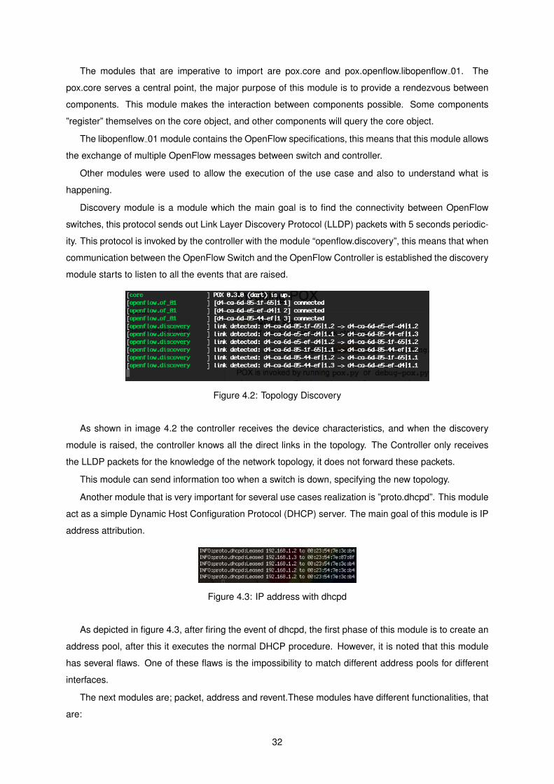
The modules that are imperative to import are pox.core and pox.openflow.libopenflow 01. The
pox.core serves a central point, the major purpose of this module is to provide a rendezvous between
components. This module makes the interaction between components possible. Some components
”register” themselves on the core object, and other components will query the core object.
The libopenflow 01 module contains the OpenFlow specifications, this means that this module allows
the exchange of multiple OpenFlow messages between switch and controller.
Other modules were used to allow the execution of the use case and also to understand what is
happening.
Discovery module is a module which the main goal is to find the connectivity between OpenFlow
switches, this protocol sends out Link Layer Discovery Protocol (LLDP) packets with 5 seconds periodic-
ity. This protocol is invoked by the controller with the module “openflow.discovery”, this means that when
communication between the OpenFlow Switch and the OpenFlow Controller is established the discovery
module starts to listen to all the events that are raised.
Figure 4.2: Topology Discovery
As shown in image 4.2 the controller receives the device characteristics, and when the discovery
module is raised, the controller knows all the direct links in the topology. The Controller only receives
the LLDP packets for the knowledge of the network topology, it does not forward these packets.
This module can send information too when a switch is down, specifying the new topology.
Another module that is very important for several use cases realization is ”proto.dhcpd”. This module
act as a simple Dynamic Host Configuration Protocol (DHCP) server. The main goal of this module is IP
address attribution.
Figure 4.3: IP address with dhcpd
As depicted in figure 4.3, after firing the event of dhcpd, the first phase of this module is to create an
address pool, after this it executes the normal DHCP procedure. However, it is noted that this module
has several flaws. One of these flaws is the impossibility to match different address pools for different
interfaces.
The next modules are; packet, address and revent.These modules have different functionalities, that
are:
32

• The packet module contains the format header for the different types of packets, such as IPv4,
IPv6, Ethernet, Address Resolution Protocol (ARP) VLANs, among others. This module permits
read the parameters inside the packet, it is mean when the packet came in the controller under-
stand the parameters and can make a match because this module.
• The address module distinguish the types of address, such as Ethernet address, IP address and
IPv6 address. This module formats the network addresses and parses the network information.
• The revent module works like the publish/ subscribe paradigm.
4.6.3 Hub and Learning Switch Use Case
Hub Use Case
The hub is a simple use case that allows the understanding of how SDN with OpenFlow works and how
the information is sent. This scenario can be done in proactive and reactive mode.
Figure 4.4: Hub Configuration in proactive and reactive mode
As can be verified in figures 4.4, the forwarding in hub mode does not differ much if mode is reactive
or proactive. The only differences between these two modes is while in reactive mode the message type
is a packet-out, because the packet is sent through a message of type packet-in. This mode represents
the situation in which a packet is sent to the controller, and the controller responds with a packet-out
with the action flood the network. The proactive mode is a bit different because the message type is
flow mod and the configuration is made in event handle ConnectionUp.
In order to execute this configuration it is important to listen for raised events from the network. In this
case, for example, the function core.openflow.addListenerByName (’PacketIn’, handle PacketIn)
should be used, this function listens to the events of the type PacketIn.
33

Learning Switch Use Case
The Learning Switch, as its name implies, is the ”brain” of the OpenFlow Switch.
This algorithm behaves in the following way; when a packet arrives to the switch a table that contains
the source port and mac address of the source is created.
1. If the Ethertype of the packet is LLDP or if the packet’s destination address is a Bridge Filtered
address
(a) Then drop packet.
2. If the destination is multicast
(a) Then flood the packet
3. Else checks if the destination MAC address is on the table
(a) If not in the table, then flood the packet
(b) Else gets the port corresponding to the MAC address from the table and verifies if the desti-
nation port is the same port of the source port packet:
i. Then drop packet
(c) Else insert a flow entry in the flow table of the OpenFlow switch. This flow statement is to
send a Packet-Out by the respective port.
Figure 4.5: Flow entry configuration
The figure 4.5 shows the configuration of an ofp flow mod type message in the learning switch. This
type of message, as stated in chapter 3, allows to modify the message type, in this use case, it is made a
match with the parameters that are in packet, using the of.ofp match.from packet(packet, event.port).
Figure 4.6: OpenFlow Switch flow entry
The flow entry ofp flow mod is added in the flow table. When packet is match, as demonstrated in
figure 4.6, this flow entry has the action send all Packet-Out by the output port 1. This action is taken by
the command msg.actions.append(of.ofp action output(port = port)).
34

4.6.4 Static Routing with Port Match Use Case
This use case allows the creation of statistic routes for the different types of packet. Before explaining the
procedure of this use case it is important to note that the hosts IP addresses were statically configured,
that is the IP address was configured directly in the host.
Figure 4.7: Communication between hosts
The network topology can be seen in figure 4.7, where two hosts are connected to two different
network devices. Host 1 has the IP address 192.168.20.2/24 and is connected to switch 1. Host 2 has
the IP address 192.168.20.3/24 and is connected to switch 3.
When host 1 wants to communicate with host 2, it sends a packet to the switch (1), since the switch
cannot match the packet to any entry in its flow table, it sends the packet to the controller through
a Packet-In (2). The controller receives the packet and sends a flow mod message(3) that has the
predefined matches by the controller and their respective functions.
Since switch 1 now knows how to handle the packet, it sends it to the output port that matches (4)
after installing the flow tables on the switch. Switch 3 does not know how the handle the packet and has
to repeat the steps taken by switch 2.
In this use case the messages are different for the various switches, allowing several switches to
have different flow tables, as can be seen in table 4.1 . This table comprises two flow entries, being an
example of how to apply the flow entries in the switch flow table.
To create this flow table in the network devices it was essential to differentiate where to send, there-
fore the function core.openflow.sendToDPID(dpid, msg) is used. This means that with this function it
is possible to send distinct flow entries to the different devices. As can be verified, it sends the message
to a specific switch.
35

Flow Match Actions
ingress port = 2 output=1
ingress port = 1 output=2
Table 4.1: OpenFlow Switch flow entry
4.6.5 Static Routing with IP Addresses Match Use Case
Another tested use case was the layer 3 static routes implementation. This use case is similar to the
previous subsection, although the level of configuration is more complex.
In the Static Routing with IP Addresses Match use case it is necessary to take into account the ARP
protocol because most of the sent packets to the Controller are from this type. As referenced in the
implementation section, the packet header, which the switch sends to the Controller, is composed by the
source MAC address, the destination MAC address and the type of packet.
It is important to mention that the Controller discard some packets from certain addresses, but also
allows to add flow entries to the switch. When a packet is sent to the Controller (a Packet In message)
it checks the type and the content of the packet, but also the next layer header. As an example, if
the header of the pack is Ethernet type, the Controller knows that the next header is Internet Protocol
Version 4 (IPv4) type and if the packet header is IPv4 type, the Controller knows that the next header is
TCP or User Datagram Protocol (UDP) type.
Next it is described in detail how the Controller handles the packets:
• The controller verifies if the switch’s Datapath ID (dpid) is in the ARPtable. If not, it adds the dpid
in the ARPtable.
• If the packet is IPv4 type, the Controller performs the following operations:
First verifies if the source address is in the ARPtable of the correspondent dpid. If found, the
Controller verifies if the source address or the destination address is unintended. In this case,
it verifies if the destination address is in the ARPtable. If the destination is in the ARPtable the
Controller gets the correspondent MAC address and the port where the packet was sent. If this
port is equal to the input port of the packet, then the packet is discarded, but if not discarded, a flow
entry is created and afterwards sent to the switch through the dpid. The flow entry is composed by
the match of the packet (to make a match it is used the command ofp match.from packet(packet,
event.port) and the instructions sent to the switch, the actions. This actions sends the packets
through the respective output port and assigns the destination MAC address to the packet.
If the destination is not in the ARPtable, the Controller sends a message with PacketOut type with
an output action to flood the network in an attempt to find the host’s destination address. If this
address is unintended, the packet is dropped and consequently the Controller adds a flow entry
without action. If the source address is not in the ARPtable, the Controller adds in the ARPtable
the source IP address, the input port and the MAC address associated with the correspondent
dpid.
36

• If the packet is ARP type, the Controller performs the following operations:
First it verifies if the type of the protocol is equal to the IPv4 in the ARP packet. If equal, the Con-
troller verifies if the type of protocol is equal to the ARP packet. If there is a match, the Controller
adds the source address, the input port and the source MAC address to the correspondent dpid in
the ARPtable.
Next, it verifies if the source address or the destination address is an unintended. If not, the
Controller verifies if the ARP operations is a request and if so, it sends the flow entry to the switch
through to the same port where the packet was received.
If the destination is not in the ARPtable, the Controller sends a packet out with the action flood,
which allows to know the MAC address corresponding to the destination IP address.
4.6.6 Modifying Actions in a Flow
This use case has been developed to explore and verify more about the software flows, this means
that when the controller establishes the connection with an OpenFlow Switch, it sends the rules or
instructions already created by the controller.
When a new host is added to the OpenFlow switch, the IP address will be different, so when the
switch receives a packet with the new address, it sends a PacketIn to the controller where it adds an
action to the switch so that it modifies the destination IP address.
This instruction can be done in two ways, either a new flow entry is created with the new destination
IP address, or the respective flow entry is modified, adding the command OFPFC MODIFY and the new
action.
Figure 4.8: Modify a specific flow entry
Figure 4.8 shows how a flow entry can be modified, it suffices to use the OFPFC MODIFY command,
this command modifies the flow entry that matches, in this case we want to add a new action, this action
allows the modification of the destination address through the set dst command.
Flow Match Actions
dl type = 0x806; nw dst = 192.168.20.2 output=3
dl type = 0x806; nw dst = 192.168.20.3 output = 2; set dst = 192.168.20.14
Table 4.2: OpenFlow Switch flow entry
37

As can be seen from table 4.2, the switch receives an instruction given by the controller that modifies
the destination address, in this case it was modified to ”192.168.20.14”
4.6.7 VLAN Use Case
Unfortunately one of the huge ideas about SDN is the configuration of VLANs with the OpenFlow pro-
tocol, but with the OpenFlow version used this was not possible, so the VLANs configuration was made
directly in the switch, and afterwards the OpenFlow protocol was used to create the flow entries.
In more detail, the simplest SDN setup is to create two VLANs; one to allow for control communica-
tions between the OpenFlow Controller and switch, and the other one for regular traffic.
In order to create VLANs, first the pc was connected to the equipment and the configuration was set
up, using the following steps:
• create the VLAN interface, and associate the port of OpenFlow switched
• add ports to the respective VLAN, aggregation mode
• in OpenFlow switch, associate the VLAN port to controller
After configuring the switch, OpenFlow recognizes those interfaces as new network ports. To modify
a VLAN port, a set vlan vid type action is used, this adds and defines the VLAN’s ID, in case there is not
a VLAN interface associated.
It is important to note that VLANs do not communicate between themselves due to the firewall rules
implemented.
VLAN construction and attribution to the different ports was done in the following way:
• a set of variables was created that will be of use to the code procedure, the most important of them
is the VLAN table, this dictionary contains the information about which IP address type the VLAN
belongs to and in which port did it emerge.
• After creating the variables, the controller starts listening.
• When the connection between the network device and the controller is established the Connec-
tionUp event is raised, triggering the controller to execute the VLANs handling/treatment.
• When the VLANs treatment is initialized, it is possible to verify that this operation is done through
distinct devices and ports. The technique used was to associate the odd ports of the OpenFlow
switch to vlan id 1 and the even ports to vlan id 2.
• After determining the VLANs, the information is added to the VLAN table dictionary. When a packet
comes in the controller configures it in such a way that it matches the vlan id, having the effect of
adding or modifying the VLAN id and flooding the network with that VLAN.
Unfortunately it was not possible to add different network addresses to different VLANs, due to dhcp
module not working as expected, it gives IP addresses from the same network to all devices that are
connected to the controller, and thus isn’t a good solution.
38

4.7 Summary
In summary, these experiments opened an array of possibilities, the most exciting one is the easy con-
figuration mode. It is very simple to create a network and as soon as an event is raised the controllers
immediately send the information to the switch. It is important to note the packet composition and type.
This is due to the fact that initially the packet only has layer 2 of the TCP/IP model, and what distin-
guishes it is the packet type. It is through the packet type that the treatment of the configuration can be
started.
39

Chapter 5
Evaluation
This chapter reproduces the results that allow a short evaluation of the SDN behavior comparing with
traditional networks and of how SDN networks perform in reactive versus proactive mode. In section 5.1
the evaluation goals are shown. In section 5.1.1 the metrics that will be used to testing the SDN are
presented. In section 5.2 there is a comparison between the traditional network and the SDN network.
In section 5.3 it is analyzed the SDN behavior considering the reactive and proactive mode and the
captured packets. Finally in section 5.4 a brief summary is made about this chapter.
5.1 Tests Objectives
The main goal of this dissertation is to prove the concept of the SDN with OpenFlow protocol, to accom-
plish this goal it is necessary to realize several tests, with packet captures from Wireshark.
These scenarios will allow the measurement of the packet transmission time, the switch flow table
installation cost and the time it takes for a switch to establish a match with a packet.
5.1.1 Metrics
This section presents a brief explanation of the evaluation metrics used to test the project. The evaluation
metrics used are flexibility and performance evaluation.
Flexibility: this metric verifies device functionality after successive configuration changes with Open-
Flow, due to the creation of several test scenarios;
Performance: this metric evaluates the performance of an OpenFlow network and is composed of
latency and throughput measurements.
5.2 SDN Network Vs Traditional Network
This section evaluate the behavior of the SDN and the traditional network.
The two test that permits to make this comparison is latency and throughput.
40

5.2.1 Latency
The main goal of this metric is to prove that SDN networks basically have better or equal latency com-
pared to traditional networks.
To achieve this goal a ping that measures the latency was necessary. These pings are made in SDN
hybrid mode.
Figure 5.1: Performance Comparison between SDN and Traditional Network
As shown in figure 5.1, the latency of the packets is better than the latency of the packets in tradi-
tional networks, though when the first packet is received by the destination the latency in SDN is higher
(118 ms) than in traditional networks, but was not shown in the figure because it would make the data
impossible to read.
This behavior happens because in a first phase the packet is sent to the controller and the flow tables
entries are installed and only after this procedure are the other packets sent to the destination.
Network Type Minimum Average MaximumTraditional Network 0.774 ms 0.803 ms 0.886 ms
Programmable Network 0.560 ms 12.336 ms 118.336 ms
Table 5.1: RTT comparison between SDN and Traditional Network
As shown in the table 5.1, the average latency is worse, because of the first packet that went to the
Controller.
5.2.2 Throughput
Throughput is the rate of successful message delivery over a communication channel. This data may
be delivered over a physical or logical link, or pass through a certain network node. The throughput is
usually measured in bits per second.
41
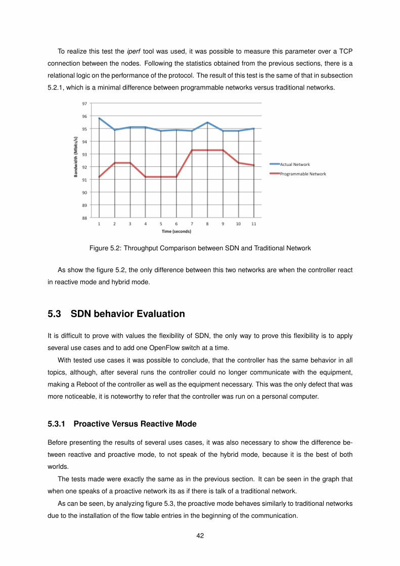
To realize this test the iperf tool was used, it was possible to measure this parameter over a TCP
connection between the nodes. Following the statistics obtained from the previous sections, there is a
relational logic on the performance of the protocol. The result of this test is the same of that in subsection
5.2.1, which is a minimal difference between programmable networks versus traditional networks.
Figure 5.2: Throughput Comparison between SDN and Traditional Network
As show the figure 5.2, the only difference between this two networks are when the controller react
in reactive mode and hybrid mode.
5.3 SDN behavior Evaluation
It is difficult to prove with values the flexibility of SDN, the only way to prove this flexibility is to apply
several use cases and to add one OpenFlow switch at a time.
With tested use cases it was possible to conclude, that the controller has the same behavior in all
topics, although, after several runs the controller could no longer communicate with the equipment,
making a Reboot of the controller as well as the equipment necessary. This was the only defect that was
more noticeable, it is noteworthy to refer that the controller was run on a personal computer.
5.3.1 Proactive Versus Reactive Mode
Before presenting the results of several uses cases, it was also necessary to show the difference be-
tween reactive and proactive mode, to not speak of the hybrid mode, because it is the best of both
worlds.
The tests made were exactly the same as in the previous section. It can be seen in the graph that
when one speaks of a proactive network its as if there is talk of a traditional network.
As can be seen, by analyzing figure 5.3, the proactive mode behaves similarly to traditional networks
due to the installation of the flow table entries in the beginning of the communication.
42

Figure 5.3: Latency in Proactive Mode Network
Figure 5.4: Latency in Reactive Mode Network
As show the figure 5.4, in reactive mode the latency is much higher because every packet has to be
processed by the controller as there is no flow table entry installation in the switches, bringing about the
bottleneck problem.
5.3.2 Packets Capture
In order to better understand how SDNs with OpenFlow works, the capture of some packets was neces-
sary, in order to understand what are the messages exchanged.
The exchange of messages and their capture was performed in several use-cases, some of them
were the Static Routing use case, Learning Switch use case and the VLANs use case.
When the network is in reactive mode flow-mod type messages are ignored, using instead Packet-
Out type messages.
As can be verified in annex A.2, the Packet-In and Packet-Out have the same packet format, however
the only difference is that Packet-Out has an instruction sent from the controller. Unfortunately this action
is not visible in Wireshark.
43

However, as mentioned in the previous paragraph, since the Packet-Out is used in reactive mode,
everything that passes through the network, goes to the Controller. Through the Packet-Out it is never
added to the dpid switch any flow entry as it can be seen in figure in the annex A.3. Unlike the Packet-
Out, the flow-mod has a different message body. As shown in figure in the annex A.4, the message body
has every match packet and presents the configuration made from the Controller.
Wireshark does no allow to see what actions are implemented in these two types of messages.
Comparing both, it is possible to conclude that when the Packet-Out is used, the switch’s flow table does
not have anything, while the flow-mod the flow entries are added.
Figure 5.5: Latency in Reactive Mode Network
As referenced in the previous section, the VLANs configurations were not expected, due to some
limitations in the OpenFlow protocol and in the software POX.
An alternative solution to these problems made it possible to create flow entries the assigned VLANs.
In the first scenario when the communication is only done with one switch, the VLANs worked as
expected. In the presented capture in figure 5.5 it is possible to see that OpenFlow sends an instruction
to the switch with VLAN id equals to 3. The instruction is intended to match the VLAN packets. This
means that a host connected to port 3 belongs to VLAN 3. When the packet matches with the flow entry,
it will be sent to the respective output port.
Unfortunately the VLAN results did not correspond to the expected because the resources were
limited.
5.4 Summary
In summary, the hosts do not know what is going on behind the network or how the network is being
managed, the results obtained show that there are no high latency values in programmable networks.
44

Chapter 6
Conclusions
6.1 Summary
Programmable networks (SDN) with the OpenFlow interface have distinguished themselves in the past
few years as a potential substitute for current networks. In order to understand the behavior of this new
paradigm the creation of a realistic environment that implements OpenFlow is necessary.
In order to make SDN more perceptible, a testbed was created implementing several use cases in
a way that this new paradigm could be understood. To make this testbed the purchase of OpenFlow
supporting devices was necessary.
This project introduces SDN as a test platform with the main goal of serving the academic and
research community of Tecnico Lisboa - Taguspark. This Thesis aims to create the testbed that will
allow some insight into OpenFlow, such as scalability, mobility and versatility possibilities.
We analyzed the architecture to create the testbed. This architecture will always have a controller that
allows transmission of instructions, management of the network, among others. This type of architecture
is centralized, bringing with it bottleneck problems.
The implementation of this architecture involved the choice of equipment and software, and justifying
the choices made. We also explain why we chose to implement these use-cases, how we did it and what
was learned from implementing them. It is in the implementation chapter that problems start to arise
and things do not turn out as expected.
Finally, to prove SDN is a valuable asset, several tests were necessary. These tests consist of net-
work analysis, how the performance compared against current networks, and if the solution is scalable
or not comparing to current networks.
After doing the network analysis, we found that SDNs are a valuable asset to the new networking
paradigm, because besides being easily configured, a significant reduction in configuration time was
observed as well reduced frustration comparing to traditional networks, which have to be configured
device by device. Beyond these advantages the results were surprising, they showed that, performance-
wise, SDNs are better than a traditional network, even though the first packet always has high latency
values, because it has to be processed by the controller, the remaining packets have lower latency
45

comparing to a traditional network.
To close the conclusion, according to demand, the created applications, the implementation of this
type of networks in big enterprises, the network’s performance level and reduction of CAPEX and OPEX,
among others, allow us to state that the networking paradigm will change in 10 years time.
6.2 Learnings and Challenges
With this Thesis we learned that what is expected, a lot of times does not happen. This investigation
required a lot of research, working to understand the theory and trying to apply the knowledge at an
applicational level, which did not happen due to obstacles that will be referenced next. It is important to
note that this dissertation should serve as a teaching to whoever chooses to study SDN. We encountered
several obstacles such as:
• The existence of little information about OpenFlow, all of it being of a more theoretical nature than
usual.
• Pox is an accessible and easily usable software, though being made by the community and non-
commercial it has many flaws, such as:
– Up until the latest version, launched in April 2014, this software did not allow instructions to
be sent to specific network devices.
– Incomplete network protocols, the biggest example being the DHCP module.
The problem with this module is that there is no way to distinguish between the interfaces,
becoming a problem to the creation of VLANs. In this case the solution adopted was to
divide IP ranges throughout the VLANs and then create a firewall rule, forbidding them to
communicate with each other.
– Another problem was encountered creating VLANs, caused by the software itself which did
not allow the creation of VLANs. The solution adopted was to create the VLANs on the switch
using them as interfaces and configuring them from the controller.
• The utilization of the oldest version of OpenFlow was another problem, making it difficult to config-
ure the network and analyzing if it could become a valuable asset.
• When the equipment arrived there were no OpenFlow packages installed, it took considerable
time to find the OpenFlow package, at the time we were seriously considering the installation of
OpenWrt.
• After searching for solutions due to POX problems, a new software controller emerged and is very
popular named OpenDaylight 1. This controller is a good alternative to POX due to the fact that it
can be a core component inside any SDN architecture. The main difference between this software
and POX, although OpenDaylight is a developed software for the community, is that it is maintained
1OpenDaylight: http://www.opendaylight.org/
46

by the Linux Foundation. This software comes with a graphical interface allowing easier network
control and programming.
It is important to mention that in the beginning of the dissertation, there was few information about
this subject and most of it was theoretical. So an implementation of SDN to understand how
it works was necessary. In October more information about this subject started to emerge and
companies began to invest in it.
Despite all these obstacles, we were able to overcome them. We learned that even though with many
research on theory the investigation of a theme less known is very complex.
We realized that in 2013 there were already developments on SDNs with OpenFlow, most of it was
theoretical, though many different software controllers were developed by equipment vendors The impact
was huge and there are an increasing number of implementation contests for use-cases on this theme.
It is also noteworthy that equipment vendors are coming up with their own solutions for SDNs, because
they do not want to lose complete control over their equipment, making researchers dependent on using
their solutions.
6.3 Future Work
For who enjoys programming in the networks area, they can improving the software Controller, POX .
This software Controller was created by the community, allowing any developer to improve the software .
Almost all modules of POX are incomplete, one of the most prominent examples is the dhcpd module. In
this case dhcpd module does not assign ranges of addresses to different interfaces, which is a serious
aspect to be improved.
Other areas that can be expanded is the implementation of a real case in the data center Tecnico
Lisboa . For this implementation it is necessary to update the OpenFlow protocol to the equipment and
the use of open source software but controlled by companies such as OpenDaylight and Floodlight.
Importantly, there are several uses case that allows them to be implemented for testing, such as
creating VLANs , load balance , among other options. There are several contests made to make the
OpenFlow a standard. So there are many use cases to be studied and implemented.
It is noteworthy that in 10 years the programmable networks will be implemented in all companies,
so future work on this subject is mainly implementing use cases or creating new network protocols.
47

Appendix A
Appendix
A.1 Packets Capture
Figure A.1: Features reply message packet capture
48

Figure A.2: Packet IN message packet capture
Figure A.3: Packet OUT message packet capture
49

Figure A.4: Flow mod message packet capture
50

Bibliography
[1] Exploring networks of the future (2013), http://www.geni.net/
[2] Jgn2plus, http://www.jgn.nict.go.jp
[3] Lavi, http://www.openflow.org/wk/index.php/LAVI
[4] Openflow switch device openflow switch device ns 3: Openflow switch device, http://www.nsnam.
org/doxygen/group__openflow.html
[5] Pica8 (2009), http://www.pica8.com/open-switching/open-switching-overview.php
[6] EstiNet 8.0 OpenFlow Network Simulator and Emulator (2010), http://www.estinet.com/
products.php
[7] Ofelia (2010), http://www.fp7-ofelia.eu/
[8] Envi (2011), http://www.openflow.org//wp/gui/
[9] Hp 3800 switch series (2011), http://h17007.www1.hp.com/us/en/networking/products/
switches
[10] NOX GUI (2012), https://github.com/noxrepo/nox-classic/wiki/NOX-GUI
[11] Floodlight Is an Open SDN Controller (2013), http://www.projectfloodlight.org
[12] Liberating network architectures with the open SDN. Big switch networks (February 2013)
[13] Mininet (2013), http://mininet.org/
[14] Open networking foundation (2013), https://www.opennetworking.org
[15] Bianco, A., Birke, R., Giraudo, L., Palacin, M.: Openflow switching: Data plane performance. In:
Communications (ICC), 2010 IEEE International Conference on. pp. 1–5 (May 2010)
[16] Casado, M., Freedman, M.J., Pettit, J., Luo, J., McKeown, N., Shenker, S.: Ethane: taking control
of the enterprise. SIGCOMM Comput. Commun. Rev. 37(4), 1–12 (Aug 2007)
[17] Chua, R.: Nox, pox and controllers galore – murphy mccauley interview (September 2012), http:
//www.sdncentral.com
51

[18] Das, S., Parulkar, G., McKeown, N.: Unifying packet and circuit switched networks. In: GLOBE-
COM Workshops, 2009 IEEE. pp. 1–6. Department of Electrical Engineering, Stanford University
(December 2009)
[19] Elby, S.: How openflow can revolutionize the carrier business (September 2012), http://www.
advancedtcasummit.com/English/Collaterals/Proceedings/2012
[20] Enterasys: Software defined networking (sdn) in the enterprise (2013), http://www.enterasys.
com/company/literature/sdn_tsbrief.pdf, secure Networks
[21] Erickson, D.: What is beacon? (February 2013), https://openflow.stanford.edu/display/
Beacon/Home
[22] Fernandez, M.: Evaluating openflow controller paradigms. In: ICN 2013, The Twelfth International
Conference on Networks. pp. 151–157 (January 2013)
[23] Foster, N., Guha, A., Reitblatt, M., Story, A., Freedman, M., Katta, N., Monsanto, C., Reich, J.,
Rexford, J., Schlesinger, C., Walker, D., Harrison, R.: Languages for software-defined networks.
Communications Magazine, IEEE 51(2), 128–134 (2013)
[24] Foundation, O.N.: Openflow switch specification version 1.3.1. Tech. rep., Open Networking Foun-
dation (September 2012)
[25] Gashinsky, I.: Sdn in warehouse scale datacenters sdn in warehouse scale datacenters v2.0 (April
2012), http://www.opennetsummit.org/archives/apr12/
[26] Henderson, T.R., Lacage, M., Riley, G.F., Dowell, C., Kopena, J.: Network simulations with the ns-3
simulator. SIGCOMM demonstration (2008)
[27] Kim, N., Kim, J.: Building netopen networking services over openflow-based programmable net-
works. In: Information Networking (ICOIN), 2011 International Conference on. pp. 525–529 (Jan-
uary 2011)
[28] Kinoshita, S., Watanabe, T., Yamato, J., Goto, H., Sone, H.: Implementation and evaluation of an
openflow-based access control system for wireless lan roaming. In: Computer Software and Appli-
cations Conference Workshops (COMPSACW), 2012 IEEE 36th Annual. pp. 82–87 (July 2012)
[29] Kobayashi, M., Seetharaman, S., Parulkar, G., Appenzeller, G., Little, J., van Reijendam, J., Weiss-
mann, P., McKeown, N.: Maturing of openflow and software defined networking through deploy-
ments (August 2012)
[30] Lantz, B., Heller, B., McKeown, N.: A network in a laptop: rapid prototyping for software-defined
networks. In: Proceedings of the 9th ACM SIGCOMM Workshop on Hot Topics in Networks. p. 19.
ACM (2010)
[31] Marist, C.: What is Avior? (2012), http://openflow.marist.edu/avior.html
52
[32] McCauley, M.: About NOX (2012), http://www.noxrepo.org/nox/about-nox/
[33] McCauley, M.: About POX (2012), http://www.noxrepo.org/pox/about-pox/
[34] McKeown, N., Anderson, T., Balakrishnan, H., Parulkar, G., Peterson, L., Rexford, J., Shenker, S.,
Turner, J.: Openflow: enabling innovation in campus networks. SIGCOMM Comput. Commun. Rev.
38(2), 69–74 (Mar 2008)
[35] Muntaner, G.: Evaluation of OpenFlow Controllers. Master’s thesis (October 2012)
[36] ONF: The google sdn wan (2012), http://www.opennetsummit.org/archives/apr12
[37] ONF: Software-defined networking: The new norm for networks (April 2012)
[38] Open vSwitch: Production quality, multilayer open virtual switch (2013), http://openvswitch.org/
features/
[39] Parulkar, G., Bernal, R., Gencel, A.: Why sdn? (2012), http://www.opennetsummit.org/
why-sdn.html
[40] Proch, D.: Controlling network flow with the openflow protocol. Tech. rep., Netronome (2012)
[41] Rotsos, C., Sarrar, N., Uhlig, S., Sherwood, R., Moore, A.W.: Oflops: An open framework for
openflow switch evaluation. In: Passive and Active Measurement. pp. 85–95. Springer (2012)
[42] Sherwood, R., Gibb, G., Yap, K.K., Appenzeller, G., Casado, M., McKeown, N., Parulkar, G.: Flowvi-
sor: A network virtualization layer. Tech. rep., Deutsche Telekom Inc., Stanford University, Nicira
Networks (October 2009)
[43] Sherwood, R., Gibb, G., Yap, K.K., Appenzeller, G., Casado, M., McKeown, N., Parulkar, G.: Can
the production network be the testbed. In: Proceedings of the 9th USENIX conference on Operating
systems design and implementation. pp. 1–6. USENIX Association (2010)
[44] Shimonishi, H.: Trema : Full-stack openflow framework in ruby and c (May 2009), http://trema.
github.io/trema/
[45] Shin, M.K., Nam, K.H., Kim, H.J.: Software-defined networking (sdn): A reference architecture and
open apis. In: ICT Convergence (ICTC), 2012 International Conference on. pp. 360–361 (October
2012)
[46] Shin, S., Kim, N., Kim, N., Kim, J.: Flow-based performance enhancements of sage visualcast-
ing using openflow programmable networking. In: Advanced Communication Technology (ICACT),
2011 13th International Conference on. pp. 1270–1274 (February 2011)
[47] Watanabe, H.: Nec programmableflow - univerge pf5820. Tech. rep., NEC (2012)
[48] Yiakoumis, Y.: Pantou : Openflow 1.0 for openwrt (2011), http://www.openflow.org/wk/index.
php/OpenFlow_1.0_for_OpenWRT
53