A Televised Berth
19
A Televised Berth by Scott St. Clair I had been a live aboard for years and not really missed having a TV on my Stevens 47, Jammin. There were a few reasons: I don’t watch much broadcast TV, and I had a laptop that allowed me to watch the occasional movie. I’m also an A/V snob: if I’m going to watch TV or a movie, I want high def video and surround sound. There are also space and power is- sues to contend with. In short, having a TV aboard seemed more trouble than it was worth. About a year ago, however, I decided that I wanted to watch the Super Bowl, so I went out and bought a 32-inch LCD-LED flat-screen TV, but where to put it? There was no free bulkhead space on which to mount it, and the thing certainly needed to be bolted down. I was also wanting some additional cabinet space. The Stevens was originally built for the bareboat charter trade, and it was long on berths and short on storage. Jammin had a pilot berth in the saloon on the starboard side above the settee. As on many boats, it mostly collected random stuff. So I decided to build cabinets in place of the pilot berth that mirrored the cabinets on the port side, with the flat screen into built into a door in between the smaller cabinets on the left and right. Seeing that the TV is only an inch and a half thick, that would leave a large space behind the TV, big enough, I figured, to install a tool chest. The Pilot Berth I’ve done a bit of finish carpentry in my time, but there were a couple of challenges I had not faced on previous projects. First, the cabinet doors on the port side are arch topped, just like most of the other doors on this Stevens. To execute the arch top, the shipwrights who built Jammin laminated thin strips of teak around what I imagined was some kind of form. It looked difficult. A second bit of carpentry I had never tried was installing cane inserts in, Scott St. Clair 1
-
Upload
scott-st-clair -
Category
Documents
-
view
239 -
download
1
description
The travails of converting an un-used pilot berth into storage cabinets and an entertainment system
Transcript of A Televised Berth
A Televised Berth
by Scott St. Clair
I had been a live aboard for years and not really missed having a TV on my Stevens 47, Jammin. There were a few reasons: I don’t watch much broadcast TV, and I had a laptop that allowed me to watch the occasional movie. I’m also an A/V snob: if I’m going to watch TV or a movie, I want high def video and surround sound. There are also space and power is-sues to contend with. In short, having a TV aboard seemed more trouble than it was worth.
About a year ago, however, I decided that I wanted to watch the Super Bowl, so I went out and bought a 32-inch LCD-LED flat-screen TV, but where to put it? There was no free bulkhead space on which to mount it, and the thing certainly needed to be bolted down. I was also wanting some additional cabinet space. The Stevens was originally built for the bareboat charter trade, and it was long on berths and short on storage.
Jammin had a pilot berth in the saloon on the starboard side above the settee. As on many boats, it mostly collected random stuff. So I decided to build cabinets in place of the pilot berth that mirrored the cabinets on the port side, with the flat screen into built into a door in between the smaller cabinets on the left and right. Seeing that the TV is only an inch and a half thick, that would leave a large space behind the TV, big enough, I figured, to install a tool chest.
The Pilot Berth
I’ve done a bit of finish carpentry in my time, but there were a couple of challenges I had not faced on previous projects. First, the cabinet doors on the port side are arch topped, just like most of the other doors on this Stevens. To execute the arch top, the shipwrights who built Jammin laminated thin strips of teak around what I imagined was some kind of form. It looked difficult. A second bit of carpentry I had never tried was installing cane inserts in,
Scott St. Clair 1
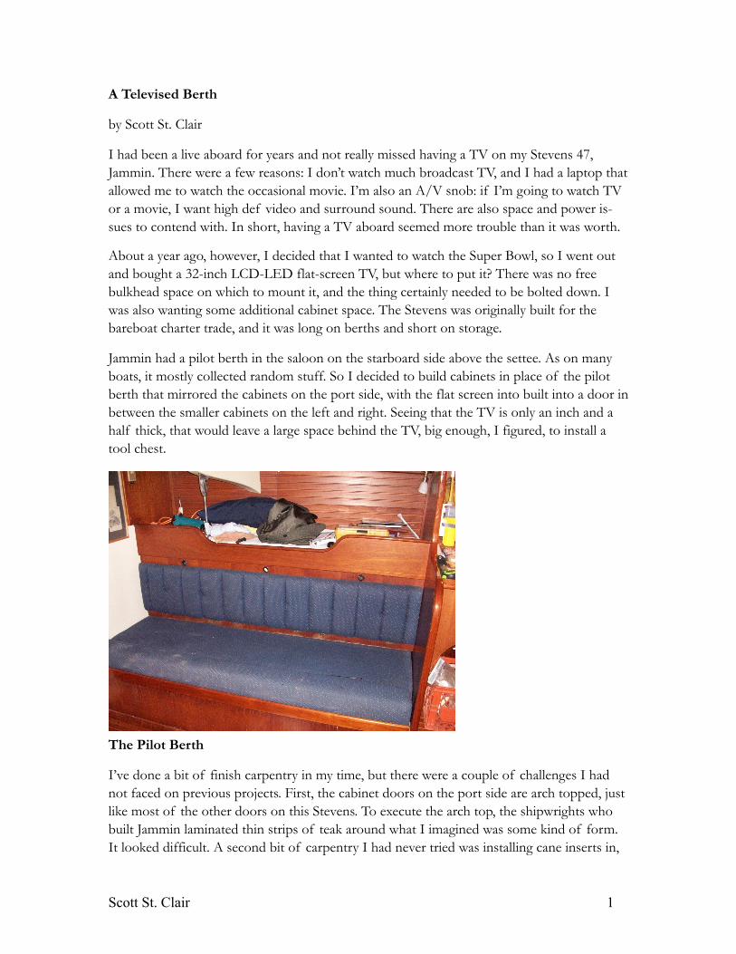
well, anything, but these doors had cane inserts. Oh well, how hard could it be? There’s al-ways the Internet.
Port Side Cabinets
Every Cabinet’s Gotta Have Guts
I started by ripping out the leeboard that formed the inside of the pilot berth. To attach the cabinet face frame to the existing bulkheads and underside of the deck, I screwed 1x2 birch furring strips around the perimeter of the opening. As on the port side, I wanted to divide the area into three portions, two cabinets with a single, fiddled shelf on either side of a larger area.
For the right most cabinet, this was straightforward. I installed a vertical partition at right angles to the cabinet face frame and the bottom of the cabinet. To secure the partition to the underside of the deck, I cut a half-inch rabbet in a 1x2 furring strip, which I screwed and epoxied to the underside of the deck. After shaping the partition and laminating Formica on either side, I simply slathered some thickened epoxy on top of the partition and slid it into place. To secure the bottom of the partition, I screwed into it through the base of the cabi-net (I know, I know. You should never screw into plywood edge on, but I didn’t want furring strips on either side and rabbeting the cabinet base wasn’t possible, at least not in my life-time).
Scott St. Clair 2
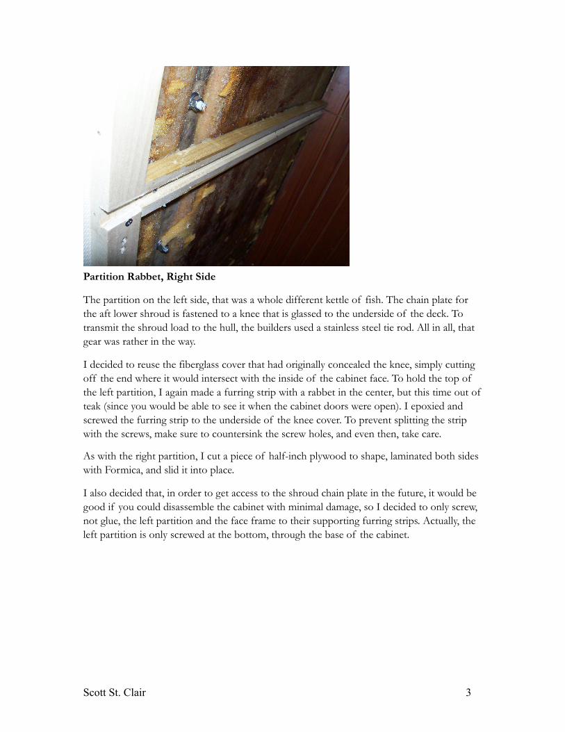
Partition Rabbet, Right Side
The partition on the left side, that was a whole different kettle of fish. The chain plate for the aft lower shroud is fastened to a knee that is glassed to the underside of the deck. To transmit the shroud load to the hull, the builders used a stainless steel tie rod. All in all, that gear was rather in the way.
I decided to reuse the fiberglass cover that had originally concealed the knee, simply cutting off the end where it would intersect with the inside of the cabinet face. To hold the top of the left partition, I again made a furring strip with a rabbet in the center, but this time out of teak (since you would be able to see it when the cabinet doors were open). I epoxied and screwed the furring strip to the underside of the knee cover. To prevent splitting the strip with the screws, make sure to countersink the screw holes, and even then, take care.
As with the right partition, I cut a piece of half-inch plywood to shape, laminated both sides with Formica, and slid it into place.
I also decided that, in order to get access to the shroud chain plate in the future, it would be good if you could disassemble the cabinet with minimal damage, so I decided to only screw, not glue, the left partition and the face frame to their supporting furring strips. Actually, the left partition is only screwed at the bottom, through the base of the cabinet.
Scott St. Clair 3
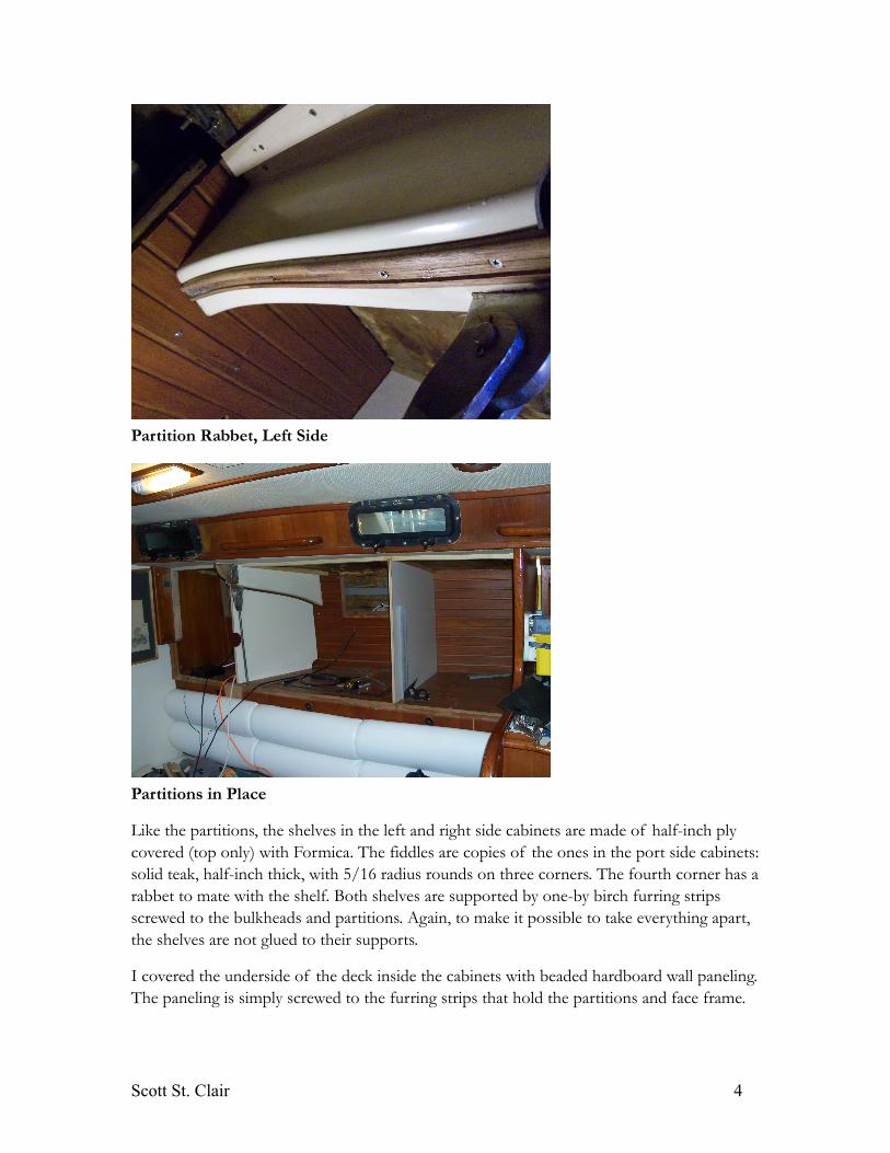
Partition Rabbet, Left Side
Partitions in Place
Like the partitions, the shelves in the left and right side cabinets are made of half-inch ply covered (top only) with Formica. The fiddles are copies of the ones in the port side cabinets: solid teak, half-inch thick, with 5/16 radius rounds on three corners. The fourth corner has a rabbet to mate with the shelf. Both shelves are supported by one-by birch furring strips screwed to the bulkheads and partitions. Again, to make it possible to take everything apart, the shelves are not glued to their supports.
I covered the underside of the deck inside the cabinets with beaded hardboard wall paneling. The paneling is simply screwed to the furring strips that hold the partitions and face frame.
Scott St. Clair 4
The paneling is attractive and cheap, though I do worry about its resistance to water. Jammin is a dry boat, but a little seepage from the genoa car track above is certainly possible.
I went the whole nine yards and installed recessed light fixtures in the paneling. The fixtures turn on automatically when you open the cabinet doors thanks to a normally closed push button switch mounted to a bracket on the face frame.
Face Frame Follies
Once the guts of the cabinets were done, I moved on to the face frame. I cut the face out of a single 8x4-sheet of half-inch ply. Because I needed the wood grain to be vertical and the grain on teak veneered ply runs parallel to the long edge (meaning it was too narrow for this application), I was forced to use plain ply for the face frame and apply a teak veneer to it (more on this later). I initially thought of this as a problem, but it turned out to be a good thing.
There were two challenges to building the face frame. The first was cutting the outside of the frame. The left and right sides were square with the bottom. The top, however, had to fit the sloping underside of the deck, which was not straight, but subtly curved. To approximate the curve of the deck, I measured every six inches from the bottom of the cabinet and added two inches for the overlap of the face with the cabinet below the new one. After cut-ting the face frame to approximate shape, I fit and trimmed it repeatedly until it fit the un-derside of the deck closely. The biggest difficultly was cutting around the shroud chain plate and tie rod where it pierced the face frame. To do so, I used one of my favorite tools, an an-gle grinder with an 8-inch sanding disk. I use this tool to shape just about everything. It’s perfect for the freeform beveling of edges, cutting of grooves and general shaping. I also used it to bevel the top of the frame to account for the camber of the deck.
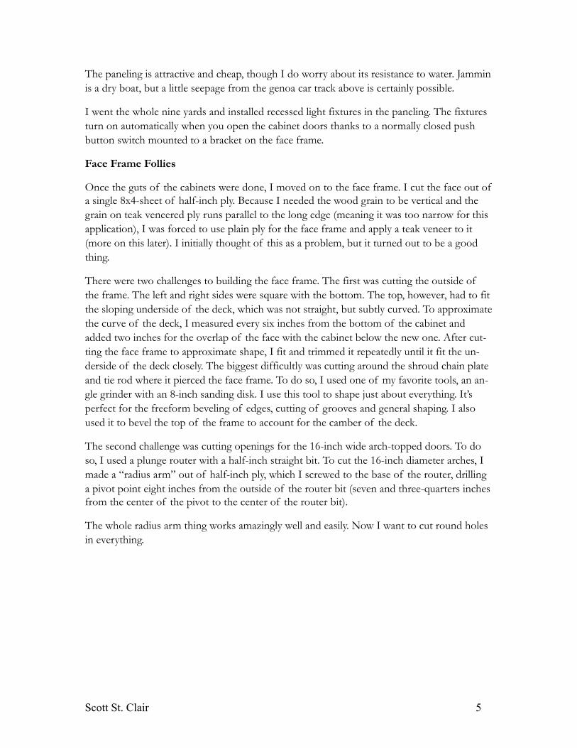
The second challenge was cutting openings for the 16-inch wide arch-topped doors. To do so, I used a plunge router with a half-inch straight bit. To cut the 16-inch diameter arches, I made a “radius arm” out of half-inch ply, which I screwed to the base of the router, drilling a pivot point eight inches from the outside of the router bit (seven and three-quarters inches from the center of the pivot to the center of the router bit).
The whole radius arm thing works amazingly well and easily. Now I want to cut round holes in everything.
Scott St. Clair 5
Cutting a Radius with the Plunge Router on a Radius Arm
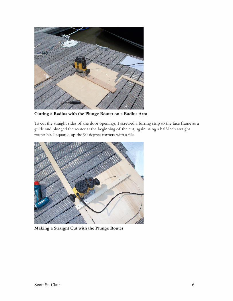
To cut the straight sides of the door openings, I screwed a furring strip to the face frame as a guide and plunged the router at the beginning of the cut, again using a half-inch straight router bit. I squared up the 90-degree corners with a file.
Making a Straight Cut with the Plunge Router
Scott St. Clair 6
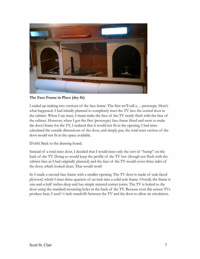
The Face Frame in Place (dry fit)
I ended up making two versions of the face frame. The first we’ll call a… prototype. Here’s what happened. I had initially planned to completely inset the TV into the central door in the cabinet. When I say inset, I mean make the face of the TV nearly flush with the face of the cabinet. However, when I got the first (prototype) face frame fitted and went to make the door/frame for the TV, I realized that it would not fit in the opening. I had miss-calculated the outside dimensions of the door, and simply put, the total inset version of the door would not fit in the space available.
D’ohh! Back to the drawing board.
Instead of a total inset door, I decided that I would inset only the sort of “hump” on the back of the TV. Doing so would keep the profile of the TV low (though not flush with the cabinet face as I had originally planned) and the face of the TV would cover three sides of the door, which looked clean. That would work!
So I made a second face frame with a smaller opening. The TV door is made of teak-faced plywood, which I inset three-quarters of an inch into a solid teak frame. Overall, the frame is one-and-a-half inches deep and has simple mitered corner joints. The TV is bolted to the door using the standard mounting holes in the back of the TV. Because even flat-screen TVs produce heat, I used ¼ inch standoffs between the TV and the door to allow air circulation.
Scott St. Clair 7
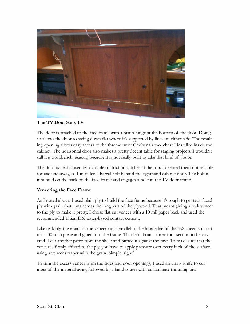
The TV Door Sans TV
The door is attached to the face frame with a piano hinge at the bottom of the door. Doing so allows the door to swing down flat where it’s supported by lines on either side. The result-ing opening allows easy access to the three-drawer Craftsman tool chest I installed inside the cabinet. The horizontal door also makes a pretty decent table for staging projects. I wouldn’t call it a workbench, exactly, because it is not really built to take that kind of abuse.
The door is held closed by a couple of friction catches at the top. I deemed them not reliable for use underway, so I installed a barrel bolt behind the righthand cabinet door. The bolt is mounted on the back of the face frame and engages a hole in the TV door frame.
Veneering the Face Frame
As I noted above, I used plain ply to build the face frame because it’s tough to get teak faced ply with grain that runs across the long axis of the plywood. That meant gluing a teak veneer to the ply to make it pretty. I chose flat cut veneer with a 10 mil paper back and used the recommended Titian DX water-based contact cement.
Like teak ply, the grain on the veneer runs parallel to the long edge of the 4x8 sheet, so I cut off a 30-inch piece and glued it to the frame. That left about a three foot section to be cov-ered. I cut another piece from the sheet and butted it against the first. To make sure that the veneer is firmly affixed to the ply, you have to apply pressure over every inch of the surface using a veneer scraper with the grain. Simple, right?
To trim the excess veneer from the sides and door openings, I used an utility knife to cut most of the material away, followed by a hand router with an laminate trimming bit.
Scott St. Clair 8
To finish the edges of the door openings, I glued a 1/8-inch strip of teak around the edges. Be really careful when sanding the trim flush with the veneer because it’s very thin, just 1/64th of an inch.
So, done, right? Not so fast.
The next morning, I came back to find that the veneer had shrunk, leaving a 1/8-inch gap where I had butted the two pieces. There where other gaps at the edges and around the openings. WTF!
I called Joe the Woodworker (the veneer guy) who said “Yep, that’s what happens with that water-based contact cement that I recommended to you”. OK...
So I made the decision to put another layer of veneer on top of the first. This time, I or-dered two-ply wood-on-wood veneer because it’s more stable, and I bought regular solvent based contact cement at good old Lowes. Both worked great: no shrinking!
I was forced to overlap the teak edging that covered the ply edges in the door openings. You can see the edge of the veneer, but after varnishing, it made no appreciable difference.
Building the Arch-Top Doors
Queen Long Marine, the yard that built the Stevens line of yachts, obviously wasn’t too wor-ried about the number of man-hours that went into their boats. The laminated arches that frame practically every door on the boat are ample evidence of that. I wanted to match the arch-top doors on the port side cabinets to make sure that it fit in with the rest of the join-ery on the boat.
The doors are 16 inches wide and 22 inches tall with cane inserts for ventilation. Each door frame is an inch and a half wide and one inch thick. The inside of the frames have a half-inch square rabbet that partially insets the door into the face frame. The outside edge has a 3/8-inch radius.
The frames were made by laminating eighth-inch strips of teak around a form. To build the form, I cut two “U” shaped sections out of half-inch ply (two were needed to get the 1 inch depth required) and screwed them to a ¾ inch ply base. I cut the outer and inner arches of the “U” using my router with the handy-dandy radius arm. The outer radius was seven and1/4 inches (14½ inches diameter) and the inner radius was six inches (12 inches in di-ameter).
To prevent the laminate from sticking to the form I covered the base and the “U” sections with plastic, which I stapled to the ply. Note that I covered the base and the “U” sections separately. It was easier that way and ensured a sharp seam between the “U” and the base.
Scott St. Clair 9
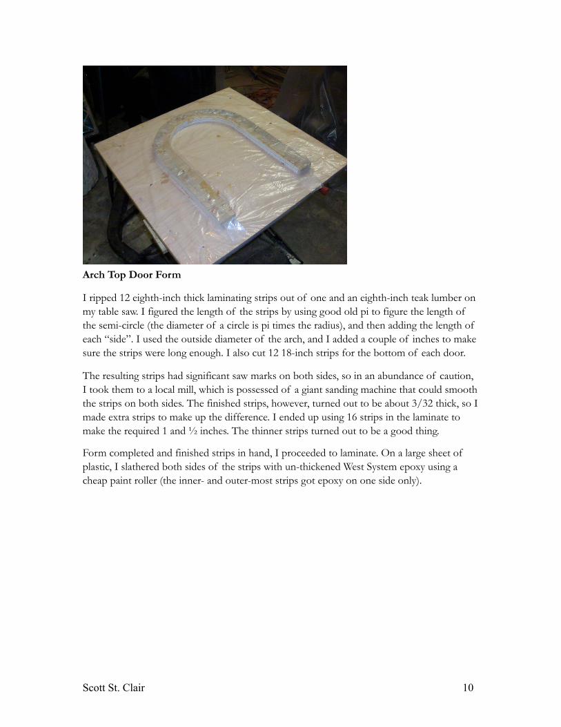
Arch Top Door Form
I ripped 12 eighth-inch thick laminating strips out of one and an eighth-inch teak lumber on my table saw. I figured the length of the strips by using good old pi to figure the length of the semi-circle (the diameter of a circle is pi times the radius), and then adding the length of each “side”. I used the outside diameter of the arch, and I added a couple of inches to make sure the strips were long enough. I also cut 12 18-inch strips for the bottom of each door.
The resulting strips had significant saw marks on both sides, so in an abundance of caution, I took them to a local mill, which is possessed of a giant sanding machine that could smooth the strips on both sides. The finished strips, however, turned out to be about 3/32 thick, so I made extra strips to make up the difference. I ended up using 16 strips in the laminate to make the required 1 and ½ inches. The thinner strips turned out to be a good thing.
Form completed and finished strips in hand, I proceeded to laminate. On a large sheet of plastic, I slathered both sides of the strips with un-thickened West System epoxy using a cheap paint roller (the inner- and outer-most strips got epoxy on one side only).
Scott St. Clair 10
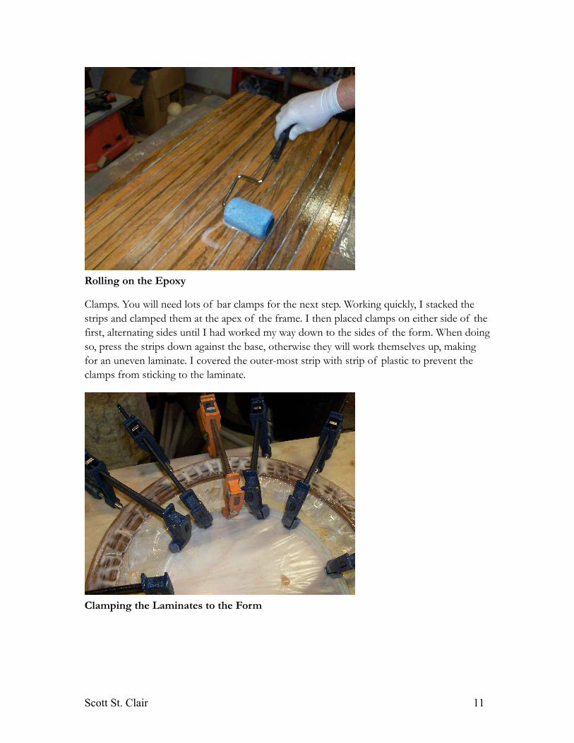
Rolling on the Epoxy
Clamps. You will need lots of bar clamps for the next step. Working quickly, I stacked the strips and clamped them at the apex of the frame. I then placed clamps on either side of the first, alternating sides until I had worked my way down to the sides of the form. When doing so, press the strips down against the base, otherwise they will work themselves up, making for an uneven laminate. I covered the outer-most strip with strip of plastic to prevent the clamps from sticking to the laminate.
Clamping the Laminates to the Form
Scott St. Clair 11
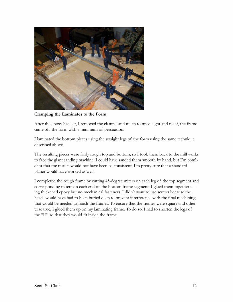
Clamping the Laminates to the Form
After the epoxy had set, I removed the clamps, and much to my delight and relief, the frame came off the form with a minimum of persuasion.
I laminated the bottom pieces using the straight legs of the form using the same technique described above.
The resulting pieces were fairly rough top and bottom, so I took them back to the mill works to face the giant sanding machine. I could have sanded them smooth by hand, but I’m confi-dent that the results would not have been so consistent. I’m pretty sure that a standard planer would have worked as well.
I completed the rough frame by cutting 45-degree miters on each leg of the top segment and corresponding miters on each end of the bottom frame segment. I glued them together us-ing thickened epoxy but no mechanical fasteners. I didn’t want to use screws because the heads would have had to been buried deep to prevent interference with the final machining that would be needed to finish the frames. To ensure that the frames were square and other-wise true, I glued them up on my laminating frame. To do so, I had to shorten the legs of the “U” so that they would fit inside the frame.
Scott St. Clair 12
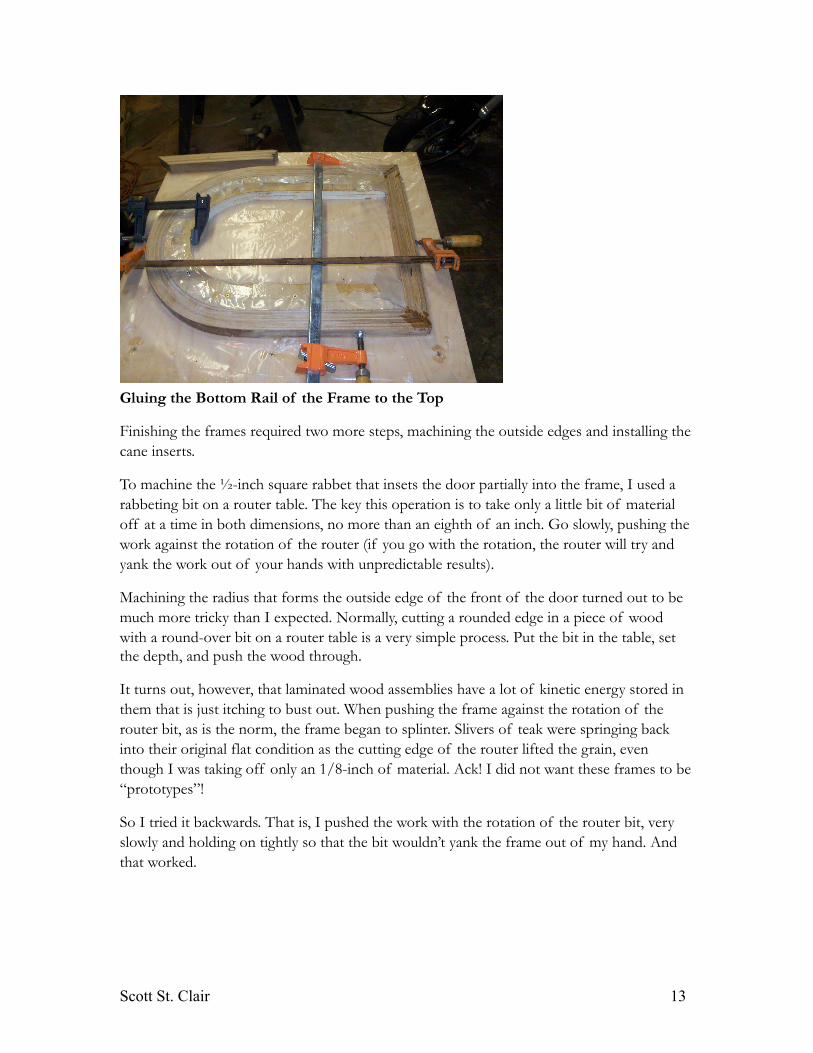
Gluing the Bottom Rail of the Frame to the Top
Finishing the frames required two more steps, machining the outside edges and installing the cane inserts.
To machine the ½-inch square rabbet that insets the door partially into the frame, I used a rabbeting bit on a router table. The key this operation is to take only a little bit of material off at a time in both dimensions, no more than an eighth of an inch. Go slowly, pushing the work against the rotation of the router (if you go with the rotation, the router will try and yank the work out of your hands with unpredictable results).
Machining the radius that forms the outside edge of the front of the door turned out to be much more tricky than I expected. Normally, cutting a rounded edge in a piece of wood with a round-over bit on a router table is a very simple process. Put the bit in the table, set the depth, and push the wood through.
It turns out, however, that laminated wood assemblies have a lot of kinetic energy stored in them that is just itching to bust out. When pushing the frame against the rotation of the router bit, as is the norm, the frame began to splinter. Slivers of teak were springing back into their original flat condition as the cutting edge of the router lifted the grain, even though I was taking off only an 1/8-inch of material. Ack! I did not want these frames to be “prototypes”!
So I tried it backwards. That is, I pushed the work with the rotation of the router bit, very slowly and holding on tightly so that the bit wouldn’t yank the frame out of my hand. And that worked.
Scott St. Clair 13
Coming Hinged
With the edges of the frames machined, the next step was to install the hinges and latch. I installed the hardware before caning the doors because it was easier, especially for the latches, since I could see and adjust the catches by just reaching though the doorframe.
The hinges were a problem: the doors I was copying had half-inch rabbets and so used semi-concealed cabinet hinges with a half-inch inset, which was a common back in the 50s and 60s. Lately? Not so much. The only partially concealed hinges available in stainless have a 3/8-inch inset, which wouldn’t work. I eventually found a chrome-plated version that did, but I had to cut off the end so that they did not over hang the edge of the frame.
The latches were easier. I used Sea Dog elbow catches very similar to the ones used by the builders. The only issue was that they were, like the hinges, too wide for the frame. Cutting them down wasn’t possible, so I added a bit of wood to the frame to make it wide enough for the latch.
The catch for the latch mounts on the underside of the cabinet shelf. With the doors mounted on the face frame, it was simple to install and align the latch and the catch.
Before moving on to caning, I put five coats of semi-gloss varnish on the frames, with the hardware removed, of course.
Can’ting
There are two meanings for the verb “cane”: one has to do with corporal punishment and the other, well, just plain punishment.
For some reason, this was the part of the project that I dreaded the most, most likely be-cause I had never done anything remotely like it.
The cane is attached to the doorframe by a reed spline embedded in a 3/16-inch groove that runs around the periphery of the frame. Cutting the groove required building a router tem-plate that could be clamped to the frame. I built the template out of half-inch ply using my trusty router and radius arm to cut the arched portion, straight furring strips to cut the sides and bottom, and a hole saw to cut the radiused lower corners.
Scott St. Clair 14
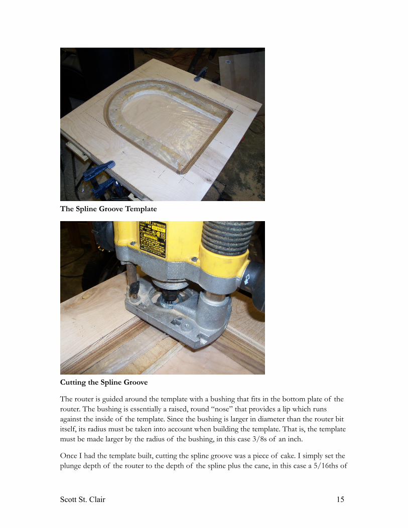
The Spline Groove Template
Cutting the Spline Groove
The router is guided around the template with a bushing that fits in the bottom plate of the router. The bushing is essentially a raised, round “nose” that provides a lip which runs against the inside of the template. Since the bushing is larger in diameter than the router bit itself, its radius must be taken into account when building the template. That is, the template must be made larger by the radius of the bushing, in this case 3/8s of an inch.
Once I had the template built, cutting the spline groove was a piece of cake. I simply set the plunge depth of the router to the depth of the spline plus the cane, in this case a 5/16ths of
Scott St. Clair 15
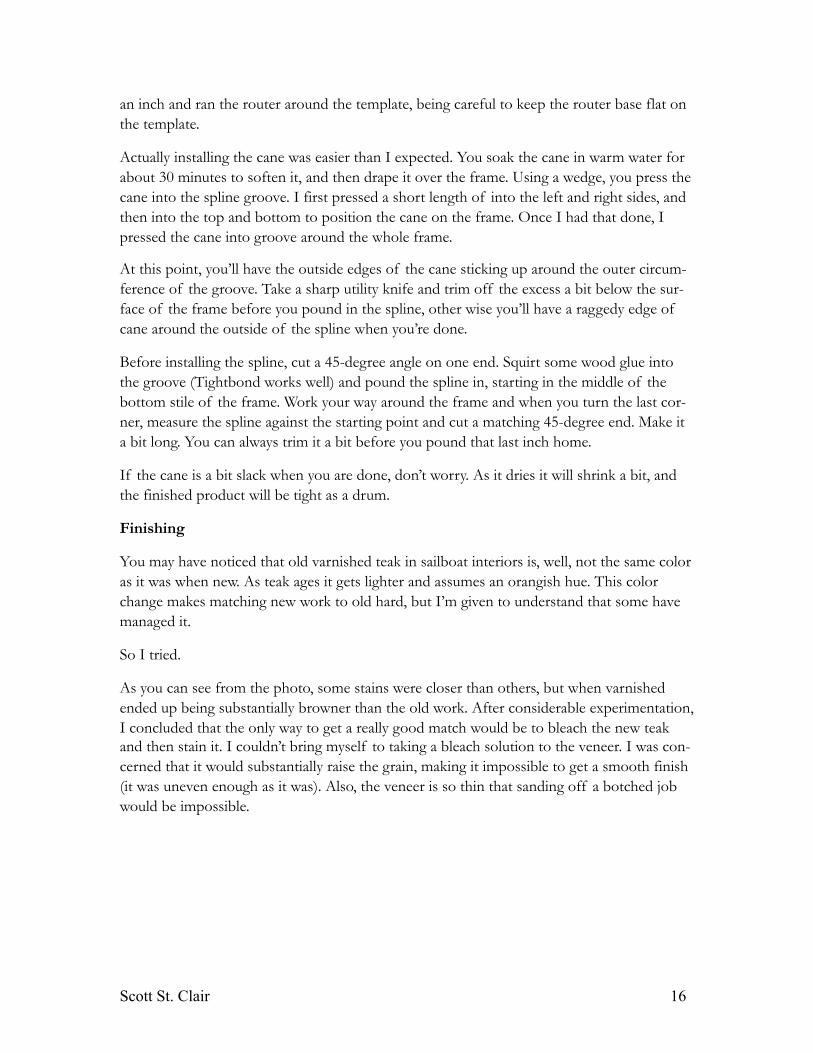
an inch and ran the router around the template, being careful to keep the router base flat on the template.
Actually installing the cane was easier than I expected. You soak the cane in warm water for about 30 minutes to soften it, and then drape it over the frame. Using a wedge, you press the cane into the spline groove. I first pressed a short length of into the left and right sides, and then into the top and bottom to position the cane on the frame. Once I had that done, I pressed the cane into groove around the whole frame.
At this point, you’ll have the outside edges of the cane sticking up around the outer circum-ference of the groove. Take a sharp utility knife and trim off the excess a bit below the sur-face of the frame before you pound in the spline, other wise you’ll have a raggedy edge of cane around the outside of the spline when you’re done.
Before installing the spline, cut a 45-degree angle on one end. Squirt some wood glue into the groove (Tightbond works well) and pound the spline in, starting in the middle of the bottom stile of the frame. Work your way around the frame and when you turn the last cor-ner, measure the spline against the starting point and cut a matching 45-degree end. Make it a bit long. You can always trim it a bit before you pound that last inch home.
If the cane is a bit slack when you are done, don’t worry. As it dries it will shrink a bit, and the finished product will be tight as a drum.
Finishing
You may have noticed that old varnished teak in sailboat interiors is, well, not the same color as it was when new. As teak ages it gets lighter and assumes an orangish hue. This color change makes matching new work to old hard, but I’m given to understand that some have managed it.
So I tried.
As you can see from the photo, some stains were closer than others, but when varnished ended up being substantially browner than the old work. After considerable experimentation, I concluded that the only way to get a really good match would be to bleach the new teak and then stain it. I couldn’t bring myself to taking a bleach solution to the veneer. I was con-cerned that it would substantially raise the grain, making it impossible to get a smooth finish (it was uneven enough as it was). Also, the veneer is so thin that sanding off a botched job would be impossible.
Scott St. Clair 16
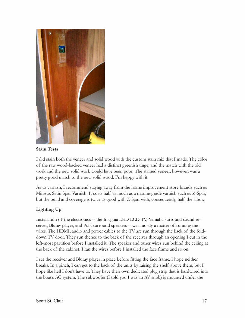
Stain Tests
I did stain both the veneer and solid wood with the custom stain mix that I made. The color of the raw wood-backed veneer had a distinct greenish tinge, and the match with the old work and the new solid work would have been poor. The stained veneer, however, was a pretty good match to the new solid wood. I’m happy with it.
As to varnish, I recommend staying away from the home improvement store brands such as Minwax Satin Spar Varnish. It costs half as much as a marine-grade varnish such as Z-Spar, but the build and coverage is twice as good with Z-Spar with, consequently, half the labor.
Lighting Up
Installation of the electronics -- the Insignia LED LCD TV, Yamaha surround sound re-ceiver, Bluray player, and Polk surround speakers -- was mostly a matter of running the wires. The HDMI, audio and power cables to the TV are run through the back of the fold-down TV door. They run thence to the back of the receiver through an opening I cut in the left-most partition before I installed it. The speaker and other wires run behind the ceiling at the back of the cabinet. I ran the wires before I installed the face frame and so on.
I set the receiver and Bluray player in place before fitting the face frame. I hope neither breaks. In a pinch, I can get to the back of the units by raising the shelf above them, but I hope like hell I don’t have to. They have their own dedicated plug strip that is hardwired into the boat’s AC system. The subwoofer (I told you I was an AV snob) is mounted under the
Scott St. Clair 17
desk in the nav station. I screwed it to the bulkhead so that it’s up off the sole. You’d never know if was there if you couldn’t, you know, feel it.
May I Have the Envelope, Please?
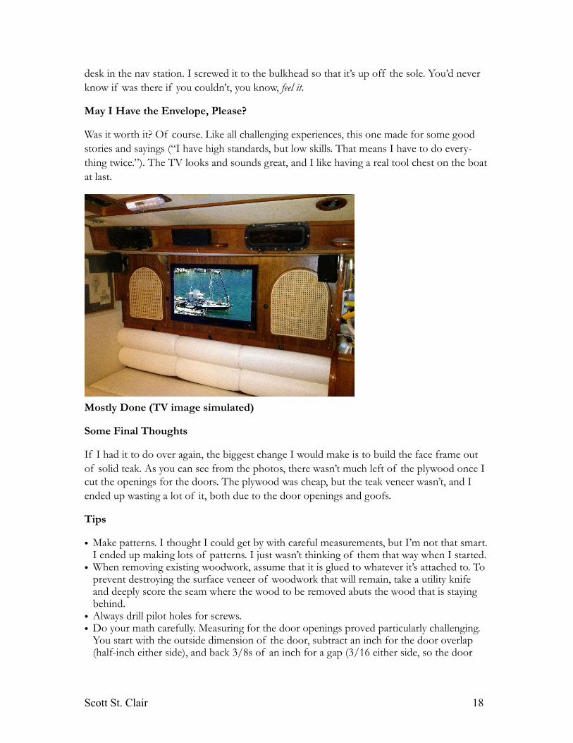
Was it worth it? Of course. Like all challenging experiences, this one made for some good stories and sayings (“I have high standards, but low skills. That means I have to do every-thing twice.”). The TV looks and sounds great, and I like having a real tool chest on the boat at last.
Mostly Done (TV image simulated)
Some Final Thoughts
If I had it to do over again, the biggest change I would make is to build the face frame out of solid teak. As you can see from the photos, there wasn’t much left of the plywood once I cut the openings for the doors. The plywood was cheap, but the teak veneer wasn’t, and I ended up wasting a lot of it, both due to the door openings and goofs.
Tips
• Make patterns. I thought I could get by with careful measurements, but I’m not that smart. I ended up making lots of patterns. I just wasn’t thinking of them that way when I started.
• When removing existing woodwork, assume that it is glued to whatever it’s attached to. To prevent destroying the surface veneer of woodwork that will remain, take a utility knife and deeply score the seam where the wood to be removed abuts the wood that is staying behind.
• Always drill pilot holes for screws.• Do your math carefully. Measuring for the door openings proved particularly challenging.
You start with the outside dimension of the door, subtract an inch for the door overlap (half-inch either side), and back 3/8s of an inch for a gap (3/16 either side, so the door
Scott St. Clair 18
will open and close) and another quarter inch to leave room for the 1/8-inch teak strip that covers the edge of the ply on the face frame. Got that?
• And then you have to lay it all out on the face frame, making sure that the openings are evenly distributed AND do not intersect the cabinet partitions. Whew. Yes, I ended up making two face frames.
• Do everything you can before you button up something like the face frame. I spent much more time installing the barrel bolt that holds the TV door closed than I needed to, but I left it until after I installed the face frame (it’s behind the frame, you idiot).
Tools Required
• Table saw• Plunge router• Router table• Various router bits, including a rabbet bit• Right-angle grinder with 8-inch sanding disc• Drill motor• Countersink bits• Veneer scraper• Many, many bar clamps
Materials Required
• Wood backed teak veneer, 4x8 sheet• Plywood, half-inch, 4x8, two sheets• Teak stock, eight board feet• Birch furring strips, 1x2, a lot• Formica, 4x8 sheet• Contact cement• Epoxy
Suppliers
• Defender (hardware and light fixtures) www.defender.com• Hardware Source (hinges) www.hardwaresource.com• Veneer Supplies (teak veneer) www.veneersupplies.com• Exotic Lumber (rough teak) www.exocticlumber.com• Lowes (miscellaneous supplies, lumber) www.lowes.com
Scott St. Clair 19