
A Technical Guide for Floor & Roof Framing Construction - Boise UK... · 4 Boise Cascade Engineered...
56
1 A Technical Guide for Floor & Roof Framing Construction June 2012
-
Upload
trankhuong -
Category
Documents
-
view
213 -
download
0
Transcript of A Technical Guide for Floor & Roof Framing Construction - Boise UK... · 4 Boise Cascade Engineered...

1
A Technical Guide for Floor & Roof Framing
Construction
June 2012
2
Boise Cascade Engineered Wood Products • Technical Guide • 06/19/2012
The SIMPLE FRAMING SYSTEM®
TABLE OF CONTENTSThe SIMPLE FRAMING SYSTEM® . . . . . . . . . . . . . . . 2Boise Cascade and the Building Regulations . . . . . 3Boise Cascade and the Environment . . . . . . . . . . . . 4Features and Beneits . . . . . . . . . . . . . . . . . . . . . . . . 5Lifetime Guarantee . . . . . . . . . . . . . . . . . . . . . . . . . . . 5Product Proiles . . . . . . . . . . . . . . . . . . . . . . . . . . . 6 - 7Design Support: BC CALC® , BC FRAMER® . . . . . . 8BCI® Joist Speciications . . . . . . . . . . . . . . . . . . . . . . 9BCI® Joists — Design Properties . . . . . . . . . . . 10 - 11 BCI® Joists Used as Joists / Beams . . . . . . . . . . . . 10 BCI® Joists Used as Rim Joists / Bearers . . . . . . . . 11 BCI® Joists Used as Columns / Studs . . . . . . . . . . . 11 BCI® Joists Used as Ties . . . . . . . . . . . . . . . . . . . . . 11 Allowable Nail Spacings . . . . . . . . . . . . . . . . . . . . . 11BCI® Joists — Floor Applications . . . . . . . . . . 12 - 35 About Floor Performance . . . . . . . . . . . . . . . . . . . . 12 Floor Design Criteria . . . . . . . . . . . . . . . . . . . . . . . . 13 Residential Floor Span Tables . . . . . . . . . . . . . . . . 14 Floor Framing Details Overview . . . . . . . . . . . . . . . 15 Floor Details . . . . . . . . . . . . . . . . . . . . . . . . . . 16 - 24 Framing Around Stair Openings . . . . . . . . . . . 25 - 26 Load Bearing External Cantilever Details . . . . . . . . 26 Temporary Construction Bracing . . . . . . . . . . . . . . 27 Hole Location and Sizing . . . . . . . . . . . . . . . . . . . . 28 Ground Floor Construction . . . . . . . . . . . . . . . . . . . 29 Fire, Sound and Air Leakage Solutions . . . . . . 30 - 35BCI® Joists — Roof Applications . . . . . . . . . . 36 - 43 Roof Design Criteria . . . . . . . . . . . . . . . . . . . . . . . . 36 Roof Rafter Span Tables – 400mm centres . . . . . 37 Roof Rafter Span Tables – 600mm centres . . . . . 38 Roof Framing Details Overview . . . . . . . . . . . . . . . 39 Roof Details . . . . . . . . . . . . . . . . . . . . . . . . . . 40 - 43VERSA-LAM® Products . . . . . . . . . . . . . . . . . . . 44 - 51 Introduction to VERSA-LAM® Products . . . . . . . . . 44 VERSA-LAM® Beam Speciications . . . . . . . . . . . . 44 VERSA-LAM® Design Properties . . . . . . . . . . . . . . 45 VERSA-LAM® Holes and Notches . . . . . . . . . . . . . 45 Allowable Nail Spacings . . . . . . . . . . . . . . . . . . . . . 46 VERSA-LAM® Used as Beams . . . . . . . . . . . . . . . . 46 Allowable Loads on VERSA-LAM® Beams . . . . . . . 47 VERSA-LAM® Used as Columns . . . . . . . . . . . . . . 48 Common Framing Details . . . . . . . . . . . . . . . . . . . . 48 Multiple Member Connectors . . . . . . . . . . . . . . . . . 49 VERSA-LAM® Products . . . . . . . . . . . . . . . . . . . . . 50 Used as Rim Material. . . . . . . . . . . . . . . . . . . . . . 50 Used as Rim Joists / Bearers . . . . . . . . . . . . . . . 50 Concentrated Load Capacities of Boise Cascade Rim Products . . . . . . . . . . . . . . . 51BCI® Joists Used as Wall Studs . . . . . . . . . . . . . . . . . 52Metalwork Connectors . . . . . . . . . . . . . . . . . . . . . . . . . 53Glossary . . . . . . . . . . . . . . . . . . . . . . . . . . . . . . . . . . 54Helpful Hints . . . . . . . . . . . . . . . . . . . . . . . . . . . . . . . 55Contact Information . . . . . . . . . . . . . . . . . Back Cover
WELCOME AND INTRODUCTION
Thank you for your interest in our company and products.
This document is the UK Technical Guide for the SIMPLE FRAMING SYSTEM® range of engineered wood products.
This version, updated as of the date listed on the cover, contains information applicable for the use of our products when designed in accordance with BS5268 Part 2 2002.
A version will be released during 2012 that will provide similar information for the use of our products when designed in accordance with EC5.
Please ensure reference to the correct information during this transition stage in the UK building codes.
ABOUT BOISE CASCADE
Boise Cascade, L.L.C. is one of the world’s largest producers of engineered wood products and a leading wholesale distributor of building materials in the United States. We are privately owned with headquarters in Boise, Idaho. Please visit www.bc.com for more information.
Boise Cascade founded its UK ofice in 1972 and has remained active in the market ever since.
In 1999 the company introduced its SIMPLE FRAMING SYSTEM® range of engineered wood products to the UK and today a network of Authorised Distributors throughout the UK and Ireland use this class-leading system to provide a wide variety of speciiers, builders and developers with competitive loor and roof solutions for use in domestic and commercial applications.
With support ofices in Chirk, Wrexham and Alton, Hampshire; the SIMPLE FRAMING SYSTEM® is a complete package providing:
Assured product provision and supply chain logistics
Environmental procurement
Regulatory authority product compliance
CAD software
Training
Design & technical support
3
06/19/2012 • Technical Guide • Boise Cascade Engineered Wood Products
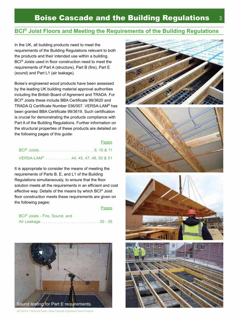
Boise Cascade and the Building Regulations
BCI® Joist Floors and Meeting the Requirements of the Building Regulations
In the UK, all building products need to meet the requirements of the Building Regulations relevant to both the products and their intended use within a building. BCI® Joists used in loor construction need to meet the requirements of Part A (structure), Part B (ire), Part E (sound) and Part L1 (air leakage).
Boise’s engineered wood products have been assessed by the leading UK building material approval authorities including the British Board of Agrement and TRADA. For BCI® Joists these include BBA Certiicate 99/3620 and TRADA Q Certiicate Number 036/007. VERSA-LAM® has been granted BBA Certiicate 99/3619. Such certiication is crucial for demonstrating the products compliance with Part A of the Building Regulations. Further information on the structural properties of these products are detailed on the following pages of this guide:
Pages
BCI® Joists . . . . . . . . . . . . . . . . . . . . . . . . .9, 10 & 11
VERSA-LAM® . . . . . . . . . . . .44, 45, 47, 48, 50 & 51
It is appropriate to consider the means of meeting the requirements of Parts B, E, and L1 of the Building Regulations simultaneously, to ensure that the loor solution meets all the requirements in an eficient and cost effective way. Details of the means by which BCI® Joist loor construction meets these requirements are given on the following pages:
Pages
BCI® Joists - Fire, Sound, and Air Leakage . . . . . . . . . . . . . . . . . . . . . . . . . . 30 - 35
Sound testing for Part E requirements.

4
Boise Cascade Engineered Wood Products • Technical Guide • 06/19/2012
Boise Cascade and the EnvironmentBoise Cascade relies on natural resources - air, water, energy, and trees – to make and distribute the wood products people use every day. We operate in ways that sustain these natural resources and protect the environment today and for generations to come. We believe good business and good environmental practices go hand-in-hand. Boise Cascade has a solid record of responsible environmental commitment and performance, including:• protecting air and water quality near our manufacturing sites
• responsibly using energy and wood resources
• reducing, reusing, and recycling manufacturing and inished product waste materials
• collaborating with others by listening to and acting on constructive ideas to demonstrate our commitment
Our performance gives substance to our commitments.Protecting air and water qualityMaking the wood products our society needs and wants requires processes that affect air and water near our manufacturing sites. Boise Cascade’s dedicated employees have established a strong track record of protecting air quality near our production sites and rigorously cleaning the water (efluent) used in manufacturing whenever it is returned to nearby rivers. Our manufacturing operations consistently meet or exceed tough standards set by multiple and complex state and federal environmental regulations.
For example: Our wood products manufacturing facilities have reduced smog-producing volatile organic compound emissions from green wood-drying operations by about 81% since 2000.
Responsibly using energy and wood resources Our manufacturing operations require substantial energy and wood resources. In addition to helping protect the environment, wisely using these resources is in our company’s best economic interest. Eficiently and responsibly using energy and wood resources keeps our operating costs lower and ensures that we sustain the natural resources essential to our business. This underlying economic link makes our commitment to environmental health and sustainability a natural priority for us. For example:
• Boise Cascade operations have reduced greenhouse gas emissions by about 5% since 2000. We joined the Environmental Protection Agency’s voluntary Climate Leaders initiative in 2005; as a result we are committed to further greenhouse gas reductions.
• Boise Cascade is committed to sustainable forestry practices. Although we don’t own timberlands, we carry independent third-party certiications as a procurer of wood ibre, as a producer of forest products, and as a purchaser of wood building materials. We don’t purchase wood from old-growth forests. Our wood procurement practices are audited and certiied annually under the Sustainable Forestry Initiative®, or SFI®; and the Programme for Endorsement of Forest Certiication, or PEFC.
• Our engineered wood products are made using about half the wood iber contained in traditional dimension lumber, resulting in superior products that more eficiently use natural raw materials.
• We track our wood iber sources to ensure that the raw material and inished products we purchase meet our rigorous environmental standards.
Reducing, reusing, and recycling Effectively reducing and reusing waste in manufacturing processes and recycling material reduces the need for “virgin” (i.e., never-before-used) raw materials, a goal that often makes both environmental and economic sense. The challenge is to eliminate as much waste as possible while productively reusing the waste that cannot be eliminated, thereby reducing our costs and the amount of material sent to landills. Processes can be changed to more eficiently use raw materials, thereby reducing the byproducts left over as waste. Products can be engineered to use manufacturing waste and waste from inished products – wood, paper, plastics, etc. For example:
• Boise Cascade’s wood products plants are designed to use almost all the wood purchased as raw material. Wood that is not manufactured into I-Joists or laminated beams typically ends up in plywood or chipped and shipped to paper mills as raw material for their products. Sawdust and plytrim is either used in particleboard or burned for fuel. Bark is either burned on-site in boilers or veneer drying system, sold for fuel at other mills or sold for landscape materials. Most of the ash generated from burning of wood fuels ends up as an agricultural soil amendment. Very little of the original raw material ends up in a landill.
• Boise Cascade works with our customers to reduce waste. Our engineered wood products are sold through Authorised Distrbutors trained in design and material management to ensure optimum yield from the stock lengths. Our BC Framer software provides eficient designs and our BC Tracker provides fast optimising to ensure minimum waste. Large users combining these software packages with our SawTek™ cutting systems can see waste down to below 1%.
Collaborating At Boise Cascade, we reach out to stakeholders to get opinions and feedback on our environmental practices. We listen to and act upon constructive ideas to demonstrate our commitment and improve our environmental performance. We believe it’s important for us to listen to and collaborate with others. For example:
• Boise Cascade has joined the Climate Leader Partnership, a voluntary effort with the Environmental Protection Agency to reduce greenhouse gas emissions by setting aggressive reduction goals and reporting our results.

5
06/19/2012 • Technical Guide • Boise Cascade Engineered Wood Products
BCI® Joists and VERSA-LAM® Products are approved for use by the BBA.
Feature BeneitLaminated Veneer Lumber (LVL)
Stable, strong and reliable engineered wood product that will not shrink, twist, cup, or bow like solid timber.
Tight manufacturing tolerancesAccurate product sizes for installation into service class 1 & 2 environments. No shrinkage - no squeaks.
Wide range of products Competitive and compatible solutions.
Clean appearanceInspires product conidence for the builder, inspector, and home buyer.
Stiff and strongQuiet, lat loors – even ceilings. No herringbone strutting / blocking required at the mid span.
Light in weight Easy to handle.
Eased edges Reduces potential splinter injuries.
Pre-stamped knock out holes Easy access for wiring and plumbing.
High performance OSB webAccommodates holes for larger services if necessary in accordance with guidelines detailed in this technical guide.
BC CALC® and BC FRAMER® Computer-aided design. Full supporting calculations and layout drawings.
Full layout drawings Easy-to-read, job-speciic joist layout plans.
Precise component packages Easy to install, no waste.
Installation guide Easy-to-read installation instructions.
Technical guide Comprehensive technical details.
Technical support team Expert help is on hand.
Site trimming Easy to cut on site using basic hand tools.
Materially eficientWise use of natural resources. The peeling process in the manufacture of LVL is a very eficient use of round log raw materials. The BCI® Joist is a very eficient structural shape.
Quality assured – BBA approved Clean, consistent, reliable products.
Lifetime guarantee Instills conidence in the products and the construction.
Lifetime GuaranteedQuality and Performance
Boise Cascade warrants its BCI® Joist, VERSA-LAM®, and ALLJOIST® products to comply with our specifications, to be free
from defects in material and workmanship, and to meet or exceed our performance
specifications for the normal and expected life of the structure when correctly
stored, installed and used according to our Installation Guide.
Gpikpggtgf"YqqfRtqfwevu
Egtvkhkecvg"Pwodgt"2581229
The SIMPLE FRAMING SYSTEM®

6
Boise Cascade Engineered Wood Products • Technical Guide • 06/19/2012
The SIMPLE FRAMING SYSTEM®
BCI® JoistsA world leader in high quality engineered wood products, Boise Cascade Engineered Wood Products offers a wide range of BCI® Joists.
BCI® Joists are manufactured to precise speciications using VERSA-LAM® laminated veneer lumber langes bonded to an orientated strand board (OSB) web.
The use of VERSA-LAM® as the lange material avoids the inherent problems that plague solid timber such as shrinking, twisting, cupping, and bowing, all of which contribute to squeaking loors.
Light in weight, yet immensely strong, the long-length BCI® Joists are quick and easy to install. Delivered to site in precise precut component packages, the SIMPLE FRAMING SYSTEM® dramatically reduces installation times and the potential for error.
Straight and true, BCI® Joists create lat loors and even ceilings. Pre-stamped holes in the OSB web allows speedy installation of wiring and plumbing. Other holes can be made in the web to accommodate larger services.
VERSA-LAM®
VERSA-LAM® provides the foundation for the SIMPLE FRAMING SYSTEM®.
Manufactured by bonding high-speciication rotary-peeled timber veneers to create huge billets of engineered wood, VERSA-LAM® is one of the strongest and most reliable engineered wood products available in the UK today.
Available in a wide range of sizes, VERSA-LAM® is an excellent partner for BCI® Joists in the SIMPLE FRAMING SYSTEM® and can also be used for a variety of purposes including loor and roof beams, lintels, purlins, columns, studs, door stock, and more.
VERSA-LAM® is popular amongst timber frame designers and manufacturers with a range of sizes suitable for timber frame as well as masonry construction.
Boise Cascade strives to lead the world in new veneer technology. Our Product Development Team continuously researches new veneer species and bonding techniques to further push the boundaries of engineered wood products.

7
06/19/2012 • Technical Guide • Boise Cascade Engineered Wood Products
VERSA-LAM® as RimVERSA-LAM® is available in a 38mm width for use as a high grade rim board in timber frame applications. It can also be used as a stairwell closure and in certain beam applications.
VERSA-LAM® has been specially developed to with-stand high compressive stresses perpendicular to the grain. This makes it ideal as a rimboard in timber frame construction to transmit the vertical loads from load-bearing walls through the loor construction to the load-bearing walls below.
The use of VERSA-LAM® can reduce the need for squash blocks in high load applications.
VERSA-LAM® is available in a range of depths to suit the other components in the SIMPLE FRAMING SYSTEM®.
VERSA-STRAND® as RimVERSA-STRAND® rim board is available in 32mm and 38mm widths for use as a high grade rim board in timber frame applications.
VERSA-STRAND® has been specially developed with one of the world’s leading OSB manufacturers to a proprietary code evaluated formula. The alternating orientation of the strands provides both vertical load and horizontal shear capacity making it ideal as a rim board in timber frame construction to transmit the vertical loads from load-bearing walls through the loor construction to the load-bearing walls below whilst providing racking resistance to the loor joist structure.
VERSA-STRAND® is a highly cost effective alternative to LSL / LVL in rim applications.
The SIMPLE FRAMING SYSTEM®

8
Boise Cascade Engineered Wood Products • Technical Guide • 06/19/2012
Design Support
BC CALC® SoftwareBC CALC® performs engineering analysis to help our customers size beams and I-joists for their building projects. It is simple to use, yet flexible enough to analyze most joist and beam applications. The user enters span, load, and hole information, and the program analyzes which of Boise Cascade’s engineered wood products are necessary for a project.
After the analysis has been run, the user may print an easy-to-read design report that clearly shows span and load information as well as analysis results. The program includes a comprehensive Help menu.
BC FRAMER® SoftwareBC FRAMER® helps our Authorised Distributors create floor and roof framing layouts quickly. This easy-to-use computer-aided 3D drafting program frames layouts and creates piece and price reports. It also draws framing drawings that use Boise Cascade’s engineered wood products and develops schedules. BC FRAMER’s editing and drawing tools allow flexibility when modifying framing layouts. The software also allows the user to customise the layout drawing with framing details, notes, symbols, and accessories.
For more information, call Boise Cascade EWP Engineering on 01420 590078.
TECHNICAL SPECSThis program is designed to work on stand-alone computers.• Current Pentium Processor• 4GB RAM (min.)• Microsoft® Intellimouse• 1024x768 or higher display• Microsoft® Windows 7 or XP ProfessionalImprovements in capacity or speed of these components will yield better performance.
BC CALC® is available for download to designers, architects, and engineers free of charge.
Please visit http://www.bc.com/wood/ewp/software/bccalc.html
9
06/19/2012 • Technical Guide • Boise Cascade Engineered Wood Products
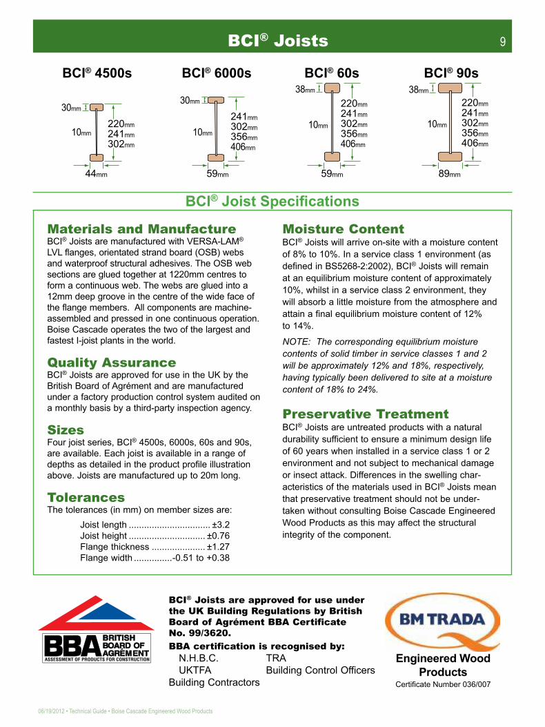
Materials and ManufactureBCI® Joists are manufactured with VERSA-LAM® LVL flanges, orientated strand board (OSB) webs and waterproof structural adhesives. The OSB web sections are glued together at 1220mm centres to form a con tinuous web. The webs are glued into a 12mm deep groove in the centre of the wide face of the flange members. All components are machine-assembled and pressed in one continuous operation. Boise Cascade operates the two of the largest and fastest I-joist plants in the world.
Quality AssuranceBCI® Joists are approved for use in the UK by the British Board of Agrément and are manufactured under a factory production control system audited on a monthly basis by a third-party inspection agency.
SizesFour joist series, BCI® 4500s, 6000s, 60s and 90s, are available. Each joist is avail able in a range of depths as detailed in the product profile illustration above. Joists are manufactured up to 20m long.
TolerancesThe tolerances (in mm) on member sizes are:
Joist length ................................ ±3.2Joist height .............................. ±0.76Flange thickness ..................... ±1.27Flange width ...............-0.51 to +0.38
Moisture ContentBCI® Joists will arrive on-site with a moisture content of 8% to 10%. In a service class 1 environment (as defined in BS5268-2:2002), BCI® Joists will remain at an equilibrium moisture content of approximately 10%, whilst in a service class 2 environment, they will absorb a little moisture from the atmosphere and attain a final equilibrium moisture content of 12% to 14%.
NOTE: The corresponding equilibrium moisture contents of solid timber in service classes 1 and 2 will be approximately 12% and 18%, respectively, having typically been delivered to site at a moisture content of 18% to 24%.
Preservative TreatmentBCI® Joists are untreated products with a natural durability sufficient to ensure a minimum design life of 60 years when installed in a service class 1 or 2 environment and not subject to mechanical damage or insect attack. Differences in the swelling char-acter istics of the materials used in BCI® Joists mean that preservative treatment should not be under-taken without consulting Boise Cascade Engineered Wood Products as this may affect the structural integrity of the component.
BCI® 4500s
10mm
30mm
220mm
241mm
302mm
44mm
BCI® 6000s
241mm
302mm
356mm
406mm
BCI® 60s BCI® 90s
30mm
38mm 38mm
10mm
220mm
241mm
302mm
356mm
406mm
220mm
241mm
302mm
356mm
406mm
10mm 10mm
59mm 59mm 89mm
BCI® Joist Speciications
BCI® Joists are approved for use under the UK Building Regulations by British Board of Agrément BBA Certificate No. 99/3620.BBA certification is recognised by: N.H.B.C. TRA UKTFA Building Control OfficersBuilding Contractors
Gpikpggtgf"YqqfRtqfwevu
Egtvkhkecvg"Pwodgt"2581229
BCI® Joists
10
Boise Cascade Engineered Wood Products • Technical Guide • 06/19/2012
BCI® Joists — Design PropertiesBCI® Joists are intended for use as structural members such as floor or roof joists, beams, rafters, wall studs or ceiling ties, in service class 1 or 2 environments as defined in BS5268-2:2002. Design properties for BCI® Joists in these internal conditions are given in the table below for long-term loading. Design prop-erties for shorter load durations may be determined by applying the appropriate value of the k3 modification factor given in BS5268-2:2002.
Notes/1 The properties given above are applicable to
long-term load duration. Permissible strength values for other load durations may be obtained by multiplying by 1.25 for medium-term loading or 1.5 for short-term loading as detailed in BS5268-2:2002.
/2 The properties given above presuppose adequate lateral restraint is provided to the compression flange via continuous boarding or discrete restraints applied at maximum centres of 400mm.
/3 For web stiffener specifications and fixing details, see page 18.
/4 The maximum deflection of a uniformly loaded joist can be calculated from the following equation :
d = (5wL4/384EI) + (wL2/8GA) where :w is the uniform load (kN/m)L is the span (m)EI is the flexural rigidity obtained from the tableGA is the shear rigidity obtained from the table
BCI® Joists Used as Joists / BeamsLong-Term Design Properties of BCI® Joists in Bending (k3 = 1.0)/1, /2
Service Class 1 Conditions — (20oC / 65% rh)Joist
Depth
JoistType
Bending Moment Capacity (kNm) Flexural
Rigidity (El)
(Nmm2 x 109)
Shear Resistance
(kN)Shear
Rigidity (GA)
(Nx106)
End Reaction (kN) Intermediate Reaction (kN)45mm Bearing 89mm Bearing 89mm Bearing 133mm BearingWeb Stiffeners Web Stiffeners Web Stiffeners Web Stiffeners
Service Class 1
Load Sharing
Non-Load
SharingLoad
SharingNon-Load
Sharing
No Yes No Yes No Yes No Yes No Yes No Yes No Yes No YesLoad Sharing Non-Load
Sharing Load Sharing Non-Load Sharing Load Sharing Non-Load
Sharing Load Sharing Non-Load Sharing
2204500s 2.0
60s 2.090s 2.0
241
4500s 2.06000s 1.8
60s 2.090s 2.0
302
4500s 2.06000s 1.8
60s 2.090s 2.0
3566000s 1.8
60s 2.090s 2.0
4066000s 1.8
60s 2.090s 2.0
Long-Term Design Properties of BCI® Joists in Bending (k3 = 1.0)/1, /2 Service Class 2 Conditions — (20oC / 85% rh)Joist
Depth
JoistType
Bending Moment Capacity (kNm)
Flexural Rigidity
(El) (Nmm2 x
109)
Shear Resistance
(kN) Shear Rigidity
(GA) (Nx106)
End Reaction (kN) Intermediate Reaction (kN)45mm Bearing 89mm Bearing 89mm Bearing 133mm BearingWeb Stiffeners Web Stiffeners Web Stiffeners Web Stiffeners
Service Class 2
Load Sharing
Non-Load
SharingLoad
SharingNon-Load
Sharing
No Yes No Yes No Yes No Yes No Yes No Yes No Yes No YesLoad Sharing Non-Load
Sharing Load Sharing Non-Load Sharing Load Sharing Non-Load
Sharing Load Sharing Non-Load Sharing
2204500s 2.0
60s 2.090s 2.0
241
4500s 2.06000s 1.8
60s 2.090s 2.0
302
4500s 2.06000s 1.8
60s 2.090s 2.0
3566000s 1.8
60s 2.090s 2.0
4066000s 1.8
60s 2.090s 2.0
Joist Depth
Joist Weight (kg/m)4500s
2.06000s
1.860s 2.0
90s 2.0
220 2.97 - 4.08 5.69
241 3.12 3.69 4.23 5.83
302 3.55 4.12 4.66 6.26
356 - 4.50 5.04 6.64
406 - 4.85 5.39 7.00
3.18 3.06 348 4.61 4.43 1.68 3.73 4.47 3.59 4.30 5.20 5.96 5.00 5.73 8.93 8.93 8.59 8.59 8.93 8.93 8.59 8.595.12 4.92 536 4.75 4.57 1.88 4.34 5.10 4.17 4.90 5.81 6.56 5.59 6.31 11.63 11.73 11.18 11.28 11.63 11.73 11.18 11.287.86 7.56 820 4.75 4.57 1.95 4.34 5.10 4.17 4.90 5.81 6.56 5.59 6.31 11.63 12.38 11.18 11.90 11.63 12.38 11.18 11.903.52 3.38 429 4.99 4.80 1.81 3.73 4.47 3.59 4.30 5.20 5.96 5.00 5.73 8.93 8.93 8.59 8.59 8.93 8.93 8.59 8.594.11 3.95 498 6.01 5.78 1.82 4.59 5.04 4.41 4.85 5.25 5.56 5.05 5.35 10.06 10.52 9.67 10.12 10.06 10.52 9.67 10.125.70 5.48 645 5.39 5.39 1.75 4.15 4.86 4.15 4.86 5.12 5.39 5.12 5.39 9.19 10.17 9.19 10.17 10.80 10.95 10.80 10.958.74 8.40 1010 5.96 5.73 1.82 5.89 5.89 5.66 5.66 5.92 5.96 5.69 5.73 12.05 12.17 11.59 11.70 12.05 12.17 11.59 11.704.51 4.34 718 6.12 5.88 2.22 3.73 4.47 3.59 4.30 5.20 6.33 5.00 6.09 8.93 8.93 8.59 8.59 8.93 8.93 8.59 8.595.26 5.06 832 7.05 6.78 2.25 4.76 5.55 4.58 5.34 5.54 6.52 5.33 6.27 10.02 10.70 9.63 10.29 10.02 10.70 9.63 10.297.44 7.15 1100 6.55 6.55 2.34 4.21 4.95 4.21 4.95 5.55 6.55 5.55 6.55 9.29 11.94 9.29 11.94 11.25 12.31 11.25 12.31
11.39 10.95 1710 7.36 7.08 2.28 6.66 7.14 6.40 6.87 7.11 7.36 6.84 7.08 12.83 14.74 12.34 14.17 12.83 14.74 12.34 14.176.25 6.01 1200 7.91 7.61 2.69 4.92 6.02 4.73 5.79 5.80 7.32 5.58 7.03 11.03 12.43 10.60 11.95 11.03 12.43 10.60 11.958.93 8.59 1610 6.85 6.85 2.86 4.67 5.28 4.67 5.28 5.85 6.85 5.85 6.85 9.29 13.41 9.29 13.41 11.42 15.03 11.42 15.03
13.70 13.17 2490 8.61 8.28 2.69 7.27 8.27 6.99 7.95 8.16 8.61 7.85 8.28 13.52 17.01 13.00 16.36 13.52 17.01 13.00 16.367.16 6.88 1610 8.70 8.37 3.06 5.20 6.43 5.00 6.18 6.13 8.06 5.89 7.75 12.40 12.97 11.92 12.47 12.40 12.97 11.92 12.479.27 8.91 1997 8.34 8.34 3.34 5.17 6.24 5.17 6.24 6.48 8.34 6.48 8.34 9.38 15.10 9.38 15.10 12.62 16.42 12.62 16.42
15.79 15.18 3340 8.24 7.92 3.06 7.08 8.13 6.81 7.82 8.24 8.24 7.92 7.92 13.08 17.59 12.58 16.91 13.08 17.59 12.58 16.91
3.18 3.06 322 3.62 3.48 1.37 2.93 3.52 2.82 3.38 4.09 4.68 3.93 4.50 7.02 7.02 6.75 6.75 7.02 7.02 6.75 6.755.12 4.92 496 3.73 3.59 1.54 3.41 4.00 3.28 3.85 4.57 5.16 4.39 4.96 9.14 9.21 8.79 8.86 9.14 9.21 8.79 8.867.86 7.56 759 3.73 3.59 1.60 3.41 4.00 3.28 3.85 4.57 5.16 4.39 4.96 9.14 9.72 8.79 9.35 9.14 9.72 8.79 9.353.52 3.38 397 3.92 3.77 1.48 2.92 3.52 2.82 3.38 4.09 4.68 3.93 4.50 7.02 7.02 6.75 6.75 7.02 7.02 6.75 6.753.70 3.56 461 5.23 5.03 1.49 3.67 4.04 3.53 3.88 4.20 4.45 4.04 4.28 8.05 8.41 7.74 8.09 8.05 8.41 7.74 8.095.14 4.94 591 5.39 5.39 1.45 4.15 4.86 4.15 4.86 5.12 5.39 5.12 5.39 9.19 10.17 9.19 10.17 10.80 10.95 10.80 10.957.86 7.56 936 4.77 4.59 1.49 4.71 4.71 4.53 4.53 4.73 4.77 4.55 4.59 9.64 9.73 9.27 9.36 9.64 9.73 9.27 9.364.51 4.34 664 3.92 3.77 1.82 2.93 3.52 2.82 3.38 4.09 4.97 3.93 4.78 7.02 7.02 6.75 6.75 7.02 7.02 6.75 6.754.73 4.55 770 6.13 5.89 1.87 3.82 4.45 3.67 4.28 4.43 5.21 4.26 5.01 8.01 8.56 7.70 8.23 8.01 8.56 7.70 8.236.68 6.43 1010 6.55 6.55 1.94 4.21 4.95 4.21 4.95 5.55 6.55 5.55 6.55 9.29 11.94 9.29 11.94 11.25 12.31 11.25 12.31
10.25 9.86 1580 5.90 5.67 1.87 5.32 5.72 5.12 5.50 5.69 5.90 5.47 5.67 10.26 11.79 9.87 11.34 10.26 11.79 9.87 11.345.63 5.41 1110 6.87 6.61 2.20 3.94 4.82 3.79 4.63 4.64 5.86 4.46 5.63 8.82 9.94 8.48 9.56 8.82 9.94 8.48 9.568.04 7.73 1480 6.85 6.85 2.37 4.67 5.28 4.67 5.28 5.85 6.85 5.85 6.85 9.29 13.41 9.29 13.41 11.42 15.03 11.42 15.03
12.32 11.85 2300 6.88 6.62 2.20 5.81 6.61 5.59 6.36 6.53 6.88 6.28 6.62 10.82 13.61 10.40 13.09 10.82 13.61 10.40 13.096.44 6.19 1490 7.57 7.28 2.51 4.16 5.15 4.00 4.95 4.90 6.45 4.71 6.20 9.92 10.37 9.54 9.97 9.92 10.37 9.54 9.979.27 8.91 2000 8.34 8.34 2.77 5.17 6.24 5.17 6.24 6.48 8.34 6.48 8.34 9.38 15.10 9.38 15.10 12.62 16.42 12.62 16.42
14.21 13.66 3090 6.58 6.33 2.51 5.67 6.20 5.45 6.25 6.58 6.58 6.33 6.33 10.46 14.07 10.06 13.53 10.46 14.07 10.06 13.53

11
06/19/2012 • Technical Guide • Boise Cascade Engineered Wood Products
Maximum Long-Term Load on BCI® Joists Subject to Uniform Compression
Perpendicular to the Joist Direction (Service Classes 1 and 2)
BCI® Joists Used as Columns / StudsThe maximum axial compression capacity of BCI® Joists used as struts should be based upon the capacity of the flange cross-section only:
Pc = jc,adm x Af x k12 x k3
Where: Pc = maximum axial compression load (N) σc,adm = 19.5 N/mm2 for Service Class 1 = 17.5 N/mm2 for Service Class 2 Af = Total cross-sectional area of the flanges (mm2) k12 = Slenderness modification factor from BS5268–2:2002 k3 = Load duration modification factor from BS5268–2:2002
BCI® Joists Used as TiesThe maximum axial tensile capacity of BCI® Joists used as struts, where both flanges are equally loaded, should be based upon the capacity of the flange cross-section only:
Pt = jt,adm x Af x k3 x (2440) 0.125
L Where: Pt = maximum axial tension load (N) σt,adm = 15.0 N/mm2 for Service Class 1 = 13.5 N/mm2 for Service Class 2 Af = Total cross-sectional area of the flanges (mm2) k3 = Load duration modification factor from BS5268–2:2002 L = Member length (mm) [min. value = 2440 mm]
Allowable Nail SpacingsNailed joints in VERSA-LAM® flanges of BCI® Joists should be designed using the permissible nail values given in BS 5268-2: 2002 for C27 timber. Nails should be spaced in accordance with the following table:
BCI® Joists Used as Rim Joists / Bearers
JoistDepth
Maximum Load per Metre Run (kN/m)
220 43.8241 42.3302 38.0356 34.2406 32.0
Nailing in Wide Face (Perpendicular to Glue Lines)Nail Diameter
(mm)End Distance
(mm)Edge Distance
(mm)Along Face -
Parallel to Grain (mm)Across Face -
Perpendicular to Grain (mm) 3.0 48 15 48 24
3.35 54 17 54 27
3.75 60 19 60 30
Nailing in Narrow Face (Parallel to Glue Lines)Nail Diameter
(mm)End Distance
(mm)Edge Distance
(mm)Along Face -
Parallel to Grain (mm)Across Face -
Perpendicular to Grain (mm) 3.0 60 15 60 15
3.35 67 17 67 17
3.75 75 19 75 19
Nailing perpendicular to Glue Lines (Wide Face)
Nailing parallel to Glue Lines (Narrow Face)
BCI® Joists — Design Properties

12
Boise Cascade Engineered Wood Products • Technical Guide • 06/19/2012
BCI® Joists — Floor Applications
About Floor PerformanceIncreasing the stiffness of a floor system will improve its performance and “feel”. The most efficient way of increasing the stiffness of the floor is to deepen the joists — this is simple engineering fact - a 25% increase in joist depth will have the same effect as doubling the joist width or halving the joist centres. A clear justifica tion for the “deeper is cheaper” statement that echoes around the engineered wood product industry. Our designers can easily design the floor to performance levels above the minimum code requirements if so desired.
The performance of a floor is matter of opinion. The “feel” that satisfies one individual may not satisfy another. Many factors affect the perceived performance of a floor. These include:
The depth of the joistThe stiffness of a floor can be markedly improved by increasing joist depth. For example, a 25% increase in joist depth will double the floor stiffness.
The spacing of the joist systemThe stiffness of a floor increases in proportion to reductions in joist spacing.
Continuous or simple spansAllowing joists to span over internal load-bearing walls instead of breaking them at these points can increase floor stiffness by up to 240%.
The decking / flooring materialThicker decking slightly improves floor performance — 22mm chipboard increases floor stiffness by 2%* compared to 18mm chipboard and means less 'local' deflection under foot.
The fixing of the decking material to the joistGluing the floor deck to the joists significantly improves floor stiffness, by as much as 70%.*
The ceiling material below the joistDirectly applied ceiling boards can improve floor performance by up to 3%.*
Level bearingsUnlevel bearings can mean joists feel "spongy" under foot near bearing positions.
The location of walls and furnitureThe position and size of dead loads on floors can either dampen or exaggerate the dynamic response of floors under foot.
*Figures established from independent laboratory research carried out on behalf of the UK Govern ment.

13
06/19/2012 • Technical Guide • Boise Cascade Engineered Wood Products
The minimum stiffness permitted for floors in BS5268-2:2002 is defined by the deflection being limited to 0.3% of the span or 14mm, whichever is the lesser. Boise Cascade recom mends that BCI® Joists are designed to higher stiff-ness criteria in order to provide superior floor performance. NHBC technical standards require that the maximum deflection is limited to 12mm. Floor performance can be enhanced consistently in practice if the decking is glued to the joist platform, as high lighted by the factors affecting floor performance. This step is also recom mended as a basis for ensuring superior floor performance in practice.
BCI® Joists are designed for floor applications using the principles of BS5268–2:2002 and the joist properties contained in BBA Certificate 99/3620. In general, it can be assumed that floors in modern centrally heated buildings will achieve a Service Class 1 moisture condition. Uniformly distributed dead and imposed loads will be assumed across the whole floor unless otherwise directed. Imposed loads are to be taken from BS6399:Part1:1996. Examples are shown below. Dead loads can be taken from the schedule of material weights tabulated below. All loads should be confirmed by the Building Designer.
BS6399:Part 1 recommends that the loads for all permanent partitions are applied in the given locations as dead loads. In practice, a standard dead load of 0.75kN/m2 is generally assumed which makes allowance for a stan dard floor construction (22mm chipboard decking + 15mm plasterboard ceiling), supporting internal non load-bearing partitions above. Exceptionally, this may be reduced to 0.5kN/m2 where no partition walls are known to exist, or increased to a higher value where a heavier form of construction is used.
Rncuvgtdqctf"
Ejkrdqctf"Hnqqtkpi"
Dqkug"Ecuecfg"Tko"Dqctf
DEK̶"Lqkuv"
Vkodgt"Uvwf"
Rctvkvkqp"
Schedule of Material Dead WeightsFloor Decking kN/m2 Ceiling Finishes kN/m2
18mm Chipboard22mm Chipboard18mm T&G Boarding22mm T&G Boarding15mm OSB18mm OSB15mm Plywood19mm Plywood18mm Particleboard/1
22mm Particleboard/1
16mm S.W. Boarding19mm S.W. Boarding12.5mm Sound Resistant P/board19mm Gypsum Plank
0.130.160.100.120.110.130.100.120.220.270.080.090.110.14
5mm Plaster Skim
15mm Plasterboard
12.5mm Plasterboard
12.5mm Firecheck P/board
0.05
0.11
0.09
0.11
Partition Loads kN/m2
12.5mm Plasterboard on timber studwork
0.29
Insulation kN/m2
Rock Wool (25mm)
Glass Fibre (50mm)
0.01
0.01
/1Particleboard refers to cement bonded particleboard Type T1 Flooring.
Standard Imposed Load AllowancesIntended Room Usage kN/m2
Domestic FloorsOffice FloorsComputer RoomsStorage RoomsGymnasiumStationery StoresBalconies
Billiard RoomsAreas with Fixed SeatingConcert HallsBedrooms in Hotels/MotelsDining Rooms/ Lounges Cafes
1.52.53.5
2.4/m height of storage5.0
4.0/m height of storageSame as rooms to which
they give access (min 1.5 for domestic use, 4.0
for public / office use)2.04.0
5.02.0
2.0
/1Taken from BS6399:Part1:1996
BCI® Joists — Floor Applications
Floor Design Criteria
14
Boise Cascade Engineered Wood Products • Technical Guide • 06/19/2012
BCI® Joists — Floor Applications
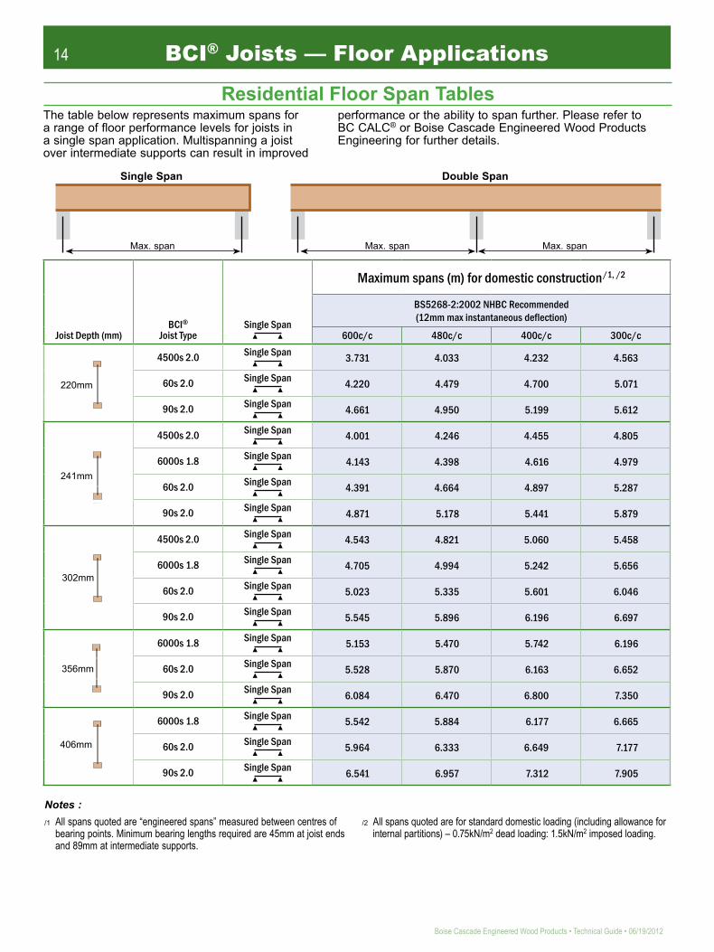
Notes :/1 All spans quoted are “engineered spans” measured between centres of
bearing points. Minimum bearing lengths required are 45mm at joist ends and 89mm at intermediate supports.
/2 All spans quoted are for standard domestic loading (including allowance for internal partitions) – 0.75kN/m2 dead loading: 1.5kN/m2 imposed loading.
Max. span Max. span Max. span
Single Span Double Span
Residential Floor Span Tables
Joist Depth (mm)BCI®
Joist TypeSingle Span
Maximum spans (m) for domestic construction/1, /2
BS5268-2:2002 NHBC Recommended (12mm max instantaneous deflection)
600c/c 480c/c 400c/c 300c/c
4500s 2.0 Single Span
60s 2.0 Single Span
90s 2.0 Single Span
4500s 2.0 Single Span
6000s 1.8 Single Span
60s 2.0 Single Span
90s 2.0 Single Span
4500s 2.0 Single Span
6000s 1.8 Single Span
60s 2.0 Single Span
90s 2.0 Single Span
6000s 1.8 Single Span
60s 2.0 Single Span
90s 2.0 Single Span
6000s 1.8 Single Span
60s 2.0 Single Span
90s 2.0 Single Span
The table below represents maximum spans for a range of floor performance levels for joists in a single span application. Multispanning a joist over intermediate supports can result in improved
performance or the ability to span further. Please refer to BC CALC® or Boise Cascade Engineered Wood Products Engineering for further details.
3.731 4.033 4.232 4.563
4.220 4.479 4.700 5.071
4.661 4.950 5.199 5.612
4.001 4.246 4.455 4.805
4.143 4.398 4.616 4.979
4.391 4.664 4.897 5.287
4.871 5.178 5.441 5.879
4.543 4.821 5.060 5.458
4.705 4.994 5.242 5.656
5.023 5.335 5.601 6.046
5.545 5.896 6.196 6.697
5.153 5.470 5.742 6.196
5.528 5.870 6.163 6.652
6.084 6.470 6.800 7.350
5.542 5.884 6.177 6.665
5.964 6.333 6.649 7.177
6.541 6.957 7.312 7.905
BCI 40s
241mm
BCI 40s
220mm
302mm
356mm
406mm

15
06/19/2012 • Technical Guide • Boise Cascade Engineered Wood Products
Hqt"vkodgt"htcog"tko"fgvcknu."ugg"H3"vq"H70"
Hqt"ownvkrng"ogodgt"eqppgevkqpu."ugg"H34"fgvcknu0"
Hqt"uvcktygnn"htcokpi"fgvcknu."ugg"rcigu"47"cpf"480"
Hqt"ocuqpt{"tko"fgvcknu."ugg"H38"vq"H3;"cpf"H430"
Hqt"hkzkpiu"vq"uvggn"dgcou."ugg"H370"Hqt"uvwf"ycnn"uwrrqtv"fgvcknu."
ugg"H5c"cpf"H9"vq"H;0"
Hqt"ecpvkngxgt"fgvcknu."ugg"H360"
Hqt"jqng"nqecvkqp"cpf"uk¦kpi"ejctv."ugg"rcig"4:0"
Uqnkf"dnqemkpi"qt"jgttkpi/dqpg"uvtwvvkpi"ku"PQV"tgswktgf"qp"vjg"UKORNG"HTCOKPI"U[UVGO̶0"Hqt"kpuvcnncvkqp"uvcdknkv{."ugg"Vgorqtct{"Eqpuvtwevkqp"Dtcekpi"fgvcknu"qp"rcig"490Vjg"hqnnqykpi"rcigu"fkurnc{"v{rkecn"hnqqt"fgvcknu0""Qvjgtu"ctg"cxckncdng"d{"tgswguv0
Hqt"ocuqpt{"ycnn"tguvtckpv"fgvcknu."
ugg"H3:0"
Floor Framing Details

16
Boise Cascade Engineered Wood Products • Technical Guide • 06/19/2012
BCI® Joists - Floor ApplicationsF1 Fixing at end bearing. F1a Party wall end bearing.
F2 BCI® Rim blocking. F3a Non load-bearing stud wall (perpendicular to joist).
F4 VERSA-LAM® or VERSA-STRAND® Rim (perpendicular to joist - external wall).
F4a VERSA-LAM® or VERSA-STRAND® Rim (perpendicular to joist - party wall).
Dqkug"EcuecfgTkodqctf0
DEK̶"Lqkuv0"
Pqvg<"Vq"cxqkf"urnkvvkpi"hncpig."uvctv"nqecvqt"pckn"cv"ngcuv"5:oo"htqo"gpf0"Pcknu"yknn"pggf"vq"dg"ftkxgp"cv"cp"cping"vq"rtgxgpv"urnkvvkpi"qh"dgctkpi"rncvg0
3/Pq"5057z87oo"nqecvqt"pckn0"
67oo"okpkowo"dgctkpi"ngpivj0"
Pqvg<"Vq"cxqkf"urnkvvkpi"hncpig."uvctv"nqecvqt"pckn"cvngcuv"5:oo"htqo"gpf0"Pcknu"yknn"pggf"vq"dg"ftkxgp
67oo"okpkowodgctkpi"ngpivj0
cv"cp"cping"vq"rtgxgpv"urnkvvkpi"qh"dgctkpi"rncvg0
Dqkug"Ecuecfg"tko0
DEK̶ "Lqkuv0
67oo"XGTUC/NCO̶
Gpf"dnqemkpi"qp"dqvjukfgu"qh"DEK̶ "Lqkuv0
DEK̶"tko"dnqemkpi0
Pqvg<"Pckn"DEK̶"tko"dnqemkpi"vq"ycnnrncvg"wukpi"5057z87oo"pcknu"gcej"ukfg"cv"522oo"egpvtgu0""Umgy"pckn"vqr"qh"dnqemkpi"vq"lqkuv0
Uqng"rncvg"vq"dg"hkzgf"vq"DEK̶"Lqkuv0
Rgtrgpfkewnct"pqp"nqcf/dgctkpi"uvwf"ycnn0
For alternative detail, see F4a
5:oo"E38"vkodgt"dnqem"hkvvgfdgvyggp"ygdu"qh"DEK̶"Lqkuv0DEK̶"dnqemkpi0
67oo"okpkowo"dgctkpi"ngpivj"hqt"DEK̶"Lqkuv0
:;oo"uvwf0
Dqkug"Ecuecfg"Tkodqctf0DEK̶"Lqkuv0
Pqvg<"Pckn"Dqkug"Ecuecfg"tko"dqctf"vq"DEK̶"Lqkuvuykvj"4"/"5057z87oo"pcknu."qpg"cv"vjg"vqr"cpf"qpg"cv"vjg"dqvvqo"*ugg"fgvckn"H3+0""
Pqvg<"Umgy"pckn"Dqkug"Ecuecfg"tkodqctf"vq"ycnnrncvgwukpi"5057z87oo"pcknu"cv"522oo"egpvtgu0"

17
06/19/2012 • Technical Guide • Boise Cascade Engineered Wood Products
F4d VERSA-BLOC™.
XGTUC/NCO̶""qh"cfgswcvg"ykfvj"vq"uwrrqtv"hnqqt"fgemkpi"cpf"rncuvgtdqctf0
Umgy"pckn"Dqkug"Ecuecfg"tkodqctf"vq"rncvg"wukpi"5057z87oo"pcknu"cv"522oo"egpvtgu0
Y4
Y4
Y
F5 VERSA-LAM® or VERSA-STRAND® Rim (parallel to joist - external wall).
F5a VERSA-LAM® or VERSA-STRAND® Rim (parallel to joist - party wall).
F6 Joist spliced on load-bearing wall. F7 Non load-bearing stud wall (parallel to joist).
Uqng"rncvg"vq"dg"hkzgf"vq"pqiikpi0"
Pqp"nqcf/dgctkpi"rctvkvkqp"ycnn0"
57z94oo"pqiikpiu"cv"822oo"egpvtgu"ykvj"¥/enkru"cv"dqvj"gpfu0"Cvvcej"ykvj"6/Pq"5097z52oo"uswctg"vykuv"pcknu0"
Hnqqt"fgem0"
DEK̶""Lqkuv"dnqemkpi"tgswktgf"yjgtg"ycnnu"ctg"pqv"dwknv"wr"vq"wpfgtukfg"qh"hnqqt"fgem0"
37z522oo"QUD"qt"rn{yqqf"urnkeg"dnqem"vq"qpg"ukfg"qpn{0"Hkz"wukpi"8/Pq"5057z87oo"pcknu."engpejgf0"
Okp0"7oo"icr"cv"vqr0"
Umgy"pckn"Dqkug"Ecuecfg"tkodqctf"vq"rncvg"wukpi"5057z87oo"pcknu"cv"522oo"egpvtgu0
DEK̶"Lqkuv"qh"cevkpi"cu"fgemkpi1"egnkpi"pqiikpi0 Y
4Y4
Y
BCI® Joists - Floor Applications
822oo"ocz0
XGTUC/DNQEª
XGTUC/NCO̶1XGTUC/UVTCPF̶
Tkodqctf0RgtrgfkewnctDEK̶"Lqkuvu0
524"ocz0
Rctcnngnvq"ycnnDEK̶"Lqkuv0
XGTUC/NCO̶1XGTUC/UVTCPF̶
Tkodqctf0
XGTUC/DNQEª
Hqt"Eqpfkvkqpu"qh"Wug"cpf"Hkzkpi"Urgekhkecvkqpu"hqt"XGTUC/DNQEª.rngcug"tghgt"vq"Dqkug"Ecuecfg"GYR"Vgejpkecn"Dwnngvkp"Pq"3/320"
P0V0U0Xgtuc/dnqeH6f
Rctv{"Ycnn0 Rctv{"Ycnn0

18
Boise Cascade Engineered Wood Products • Technical Guide • 06/19/2012
BCI® Joists - Floor ApplicationsF8 Wall to wall load transfer (BCI® Joist blocking).
F8a Wall to wall load transfer (squash blocks).
F9 Concentrated load transfer (squash blocks). F11 Backer block (face mount hanger).
F10 Web stiffeners (ixing and speciication).
Hceg"oqwpv"lqkuv"jcpigt0
Dcemgt"dnqem"tgswktgf"qp"dqvj"ukfgu"qh"ygd0
Pqvg<"Hkz"dcemgt"dnqem"wukpi":/Pq"5057z87oo"pcknu"engpejgf"*ugg"H33d+0"Wug"322oo"pcknu"hqt";2u"ugtkgu"lqkuv0
Jkij"xgtvkecn"nqcf0"
Rtqxkfg"uswcuj"dnqemu"yjgtg"xgtvkecn"nqcf"gzeggfu"tko"ecrcekv{"*ugg"rcig"73"qh"vjg"vgejpkecn"iwkfg+0"
82oo"okp0
Uocnn"icr<"5oo"okp0"72oo"ocz0
QUD"qt"Rn{yqqf"ygd"uvkhhgpgt<
72oo"okp0
72oo"okp0
Lqkuv"Fgrvj
463 4/Pq"5057z87oo442 4/Pq"5057z87oo
524 5/Pq"5057z87oo578 7/Pq"5057z87oo628 8/Pq"5057z87oo
"6722u"Ugtkgu"""""38z82oo"okp0"8222u"Ugtkgu"""""44z82oo"okp0
Hkzkpiu
";2u"Ugtkgu"""""""""5:z82oo"okp0"
Pqvg<"Wug"5057"z";2oo"pcknu"hqt";2u"Ugtkgu"Lqkuvu0
Kpvgtogfkcvg"
Vkijv"Hkv0 Vkijv"Hkv0
Vkijv"Hkv0 Vkijv"Hkv0
Gpf"Dgctkpiu0
Rctvkcn"Fgrvj"Jcpigtu*pqv"uwrrqtvkpi"vqr"hncpig+0 Eqpegpvtcvgf"Nqcfu0
Dgctkpiu0
4"pcknu0
442o
o463o
o
82oo"okp0
??
?
5"pcknu0
524o
o
82oo"okp0
??
??
7"pcknu0
578o
o
??
??
8"pcknu0
628o
o
??
??
47oo"okp0
82oo"okp0
47oo"okp0 47oo"okp0
Ygd"uvkhhgpgtu"oc{"dg"wugf"vq"kpetgcug"cnnqycdng"tgcevkqp"xcnwgu"kp"vjg"crrnkecvkqpu"dgnqy0
Pqvg<"Ygd"uvkhhgpgtu"ctg"pqv"tgswktgf"hqt"DEK̶"Lqkuvu"wpnguu"wugf"kp"jcpigtu"vjcv"fq"pqv"gzvgpf"wr"vq"tguvtckp"vjg"vqr"hncpig"qh"vjg"DEK̶"Lqkuv"qt"cu"tgswktgf"d{"fgukip0"
Cnn"Pcknu"vq"dg"5057"z"87oo"ftkxgp"vjtqwij"cpf"engpejgf"qxgt"qp"hct"ukfg0
"82u"Ugtkgu"""""""""44z82oo"okp0"
Uswcuj"dnqemu"*5:z:;oo"okp0+"
Nqcf/dgctkpi"ycnn"cdqxg"*cnkipgf"qxgt"ycnn"dgnqy+0"
:;oo"okp0"4oo"
Wug"67oo"XGTUC/NCO̶"dnqemkpi"kp"ctgcu"yjgtg"5"qt"oqtg"ownvkrng"uvwfu"ctg"wugf0
Nqcf/dgctkpi"kpvgtpcn"ycnn"rgtrgpfkewnct"vq"lqkuv"fktgevkqp"cpf"cnkipgf"ykvj"ycnn"dgnqy0
Wug"DEK̶"Lqkuv"dnqemkpi"yjgtg"nguu"vjcp"5"ownvkrng"uvwfu"ctg"wugf0
Pqvg<"Pckn"dnqemkpi"vq"ycnnrncvg"wukpi"5057z87oo"okp0"pcknu"cv"522oo"egpvtgu0
DEK̶"Lqkuv"dnqemkpi0

19
06/19/2012 • Technical Guide • Boise Cascade Engineered Wood Products
97 97 97522
Ugtkgu"""""""Dcemgt"Dnqem"Vjkempguu"6722u"""""3:oo"yqqf"rcpgn"8222u"""""47oo"yqqf"rcpgn"82u"""""""""47oo"yqqf"rcpgnu";2u""""""""3:oo"-"44oo"yqqf"rcpgnu
"Fgrvj Dcemgt"Dnqem"Fgrvju
"463oo"""""""""""""369oo"442oo"""""""""""""344oo
"524oo"""""""""""""43;oo"578oo"""""""""""""48;oo"628oo"""""""""""""53;oo
? ?5057z97oo"pcknu"engpejgf*;2oo"pcknu"hqt"
;2u"Ugtkgu"Lqkuvu+0"Yjgtg"pcknu"ctg"engpejgf."cnn"pcknu"ecp"dg"ftkxgp"htqo"pgct"ukfg0"
F11a Backer block (top hung hanger). F11b Backer block (ixing and speciication).
F11c No backer block required (Cullen U hanger).
F11d No backer block required (Simpson Strong-Tie ITB hanger).
F12 Filler block (ixing and speciication). F12a 2-ply BCI® iller block.
Vqr"hncpig"lqkuv"jcpigt0
Vkijv"hkv0
Ykvj"vqr"hncpig"jcpigtu."dcemgt"dnqem"owuv"dg"kpuvcnngf"vkijv"vq"vjg"wpfgtukfg"qh"vqr"hncpig0""Dcemgt"dnqem"tgswktgf"qp"dqvj"ukfgu"qh"ygd0
Pqvg<"Hkz"dcemgt"dnqem"wukpi":/Pq"5057z87oo"pcknu"engpejgf"*ugg"H33d+0"Wug"322oo"pcknu"hqt";2u"ugtkgu"lqkuv0
W"Jcpigt"hkzgf"wukpi"5097z52oo"uswctg"vykuv"pcknu"vjtqwij"cnn"jqngu
Vqr"rncvg"qh"jcpigt"dgpv"qpukvg"vq"hkv"
vkijv"qxgt"DEK̶vqr"hncpig0
DEK̶"Lqkuvu"fq"pqv"tgswktg"Dcemgt"Dnqemu"yjgp"W"jcpigtu"ctg"wugf"cu"fgvckngf0
DEK̶ "Lqkuvu"*82u"(;2u"tcpig"qpn{+0
Uchg"Yqtmkpi"Nqcf"hqt"hwnn{pckngf"jcpigt"cu"fgvckngf"cdqxg"ku"6085mP"*nqpi"vgto+0
Jcpigtu"vq"dg"wugf"hwnn{"kp"ceeqtfcpeg"ykvj"Ewnngp"Dwknfkpi"Rtqfwevu"urgekhkecvkqpu0
Hkz"4/rn{"DEK̶"Lqkuvu"vqigvjgt"wukpi"hknngt"dnqemu"cv"cnn"dgctkpi"rqkpvu."cv"kpeqokpi"nqcf"rqukvkqpu."cpf"cv"ocz"508o"egpvtgu"*ugg"H34d+0"
Ugg"H34"hqt"hkzkpi"fgvcknu0"
322
??
??
Ugtkgu"""""""Hknngt"Dnqem"Vjkempguu
6722u" 57oo"Vkodgt8222u" 69oo"Vkodgt82u" 69oo"Vkodgt;2u" 97oo"Vkodgt
"Fgrvj""""""Hknngt"Dnqem"Fgrvj442oo" 344oo463oo" 369oo524oo" ;9oo"-"344oo578oo" 344oo"-"369oo628oo" 369oo"-"394oo
Icr"tgswktgf"vq"cxqkf"hqtegf"hkv0
72 72822
322 322 322 3225057z97oo"pcknu"
engpejgf
Dcemgt"Dnqemu"ctg"pqv"tgswktgf"yjgp"KVD"jcpigtu"ctg"wugf0
KVD"Jcpigt"hkzgf"wukpi"c"okpkowo"qh"34/Pq"5097z52oo"uswctg"vykuv"pcknu"kpvq"hncpigu"qh"uwrrqtvkpi"lqkuv0
Jcpigt"uchg"yqtmkpi"nqcf"/""602mP0
Jcpigtu"vq"dg"wugf"kp"ceeqtfcpeg"ykvj"Ukoruqp"Uvtqpi/Vkg̶"urgekhkecvkqpu0
BCI® Joists - Floor Applications

20
Boise Cascade Engineered Wood Products • Technical Guide • 06/19/2012
BCI® Joists - Floor ApplicationsF12b Filler block (short length option). F12c Filler block (full length option).
F12d 2-ply BCI® (Cullen I-clip).
F12e Cullen I-Clip (Localized connection).
F12f Cullen I-Clip (Multiple connection).
F13 BCI® Joist to VERSA-LAM® connection.
K/Enkru"hwnn{"pckngf"wukpi"5097oo"uswctg"vykuv"pcknu0
Pqvg<""K/Enkru"vq"dg"kpuvcnngf"kp"ceeqtfcpeg"ykvj"ocpwhcevwtgtÓu"kpuvtwevkqpu0
Hkz"4/rn{"DEK̶"Lqkuvu"vqigvjgt"wukpi"K/Enkru"nqecvgf"ykvjkp"422oo"qh"cnn"dgctkpi"rqkpvu"cpf"kpeqokpi"nqcf"rqukvkqpu"cpf"cv"ocz"402o"egpvtgu"*ugg"H34g+0
4/Pq"K/Enkru"hkzgf"gcej"ukfg"qh"lqkuv"yjgtg"kpeqokpi"nqcf"ku"itgcvgt"vjcp"908mP0
Kpvgtogfkcvg"K/Enkr"kpuvcnngf"yjgtg"tgswktgf0
3/Pq"K/Enkr"hkzgf"gcej"ukfg"qh"lqkuv"yjgtg"kpeqokpi"nqcf"ku"908mP"qt"nguu0
422oo0"
402o"ocz0"
422oo0"402o"ocz0
4/Pq"K/Enkru"hkzgf"dgvyggp"lqkuvu"yjgtg"kpeqokpi"rqkpv"nqcfu"ctg"itgcvgt"vjcp"50:mP0
3/Pq"K/Enkr"hkzgf"dgvyggp"lqkuvu"yjgtg"kpeqokpi"rqkpv"nqcfu"ctg"50:mP"qt"nguu"*ugg"H34f+0
XGTUC/NCO̶"dgco0"
Hceg"hkzgf"qt"vqr"hncpig"jcpigt0"
Pqvg<""Ygd"uvkhhgpgtu"ctg"tgswktgf"yjgtg"ukfgu"qh"jcpigt"fq"pqv"gzvgpf"wr"vq"ikxg"tguvtckpv"vq"vjg"vqr"hncpig"*ugg"H32+0
Pqvg<"Oczkowo"urcekpi"dgvyggp"hknngt"dnqemu"vq"dg"508"ogvtgu0""Kpvgtogfkcvg"hknngt"dnqemu"ujqwnf"dg"kpuvcnngf"dgvyggp"dgctkpi"cpf"kpeqokpi"nqcf"rqukvkqpu0
"
Kpvgtogfkcvg"hknngt"dnqem"kpuvcnngf"yjgtg"tgswktgf0"
508o"oczkowo0"
Hknngt"dnqem""*ugg"H34"hqt"hkzkpi"fgvcknu+0"
508o"oczkowo0"
" Pqvg<"C"eqpvkpwqwu"hknngt"cpf"dcemgt"dnqem"ujqwnf"dg"eqpukfgtgf"yjgtg"pwogtqwu"kpeqokpi"lqkuvu"qeewt0"
*Ugg"H33d"cpf"H34"hqt"hkzkpi"fgvcknu0+Eqpvkpwqwu"dcemgt"dnqem0"
Hknngt"dnqem0"

21
06/19/2012 • Technical Guide • Boise Cascade Engineered Wood Products
DEK̶"Lqkuv"dnqemkpi"tgswktgf"hqt"cnn"ecpvkngxgt"eqpfkvkqpu0"
Ocz0"315tf"dcem"urcp0"
Enquwtg0"
Hkz"wukpi"5057z87oo"pcknu"cv"522oo"egpvtgu0"
822oo"
822oo"
DEK̶"Lqkuv"dnqemkpi"
tgswktgf"hqt"ecpvkngxgt0"
Uvtwevwtcn"rcpgn"enquwtg0"
Ygd"uvkhhgpgt"oc{"dg"tgswktgf"qp"gcej"ukfg"
qh"lqkuvu0"
Uvtwevwtcn"rcpgn"tgkphqtegogpv0"
Dcemgt"dnqem0"
F14 Typical standard cantilever. F14a Typical cantilever with wall support.
F15 Support at steel beam (top lange hanger on timber plate).
F15a Steel beam support within loor (face ixed hanger with timber packing).
F15b Steel beam support at edge of loor (face ixed hanger with timber packing).
F15c Steel beam support(masonry hanger shot ired to steel).
57oo"vjkem"okpkowo"vkodgt"rncvg"vq"Dwknfkpi"Fgukipgtu"urgekhkecvkqp"*vq"qxgtjcpi"gfigu"qh"uvggn"dgco"d{"5oo0+"
Vqr"hncpig"jcpigt0" Hceg"hkzgf"jcpigt"hwnn{"pckngf"vq"
vkodgt"rcemkpi0"
Uvggn"dgco"vq"dg"rcemgf"ykvj"E38"vkodgt"cpf"hkzgf"vq"Dwknfkpi"Fgukipgtu"urgekhkecvkqp0"
Hnqqt"fgem0"
Vkodgt"rcemu"hkzgf"vjtqwij"ygd"qh"uvggn"dgco"vq"Dwknfkpi"Fgukipgtu"urgekhkecvkqp0"
Hceg"hkzgf"jcpigtu"pckngf"vq"vkodgt"rcemkpi0"
Ocuqpt{"jcpigt"ujqv"hktgf"vq"vqr"qh"uvggn"dgco"vq"Dwknfkpi"Fgukipgtu"urgekhkecvkqp0" Uvggn"dgco0"
BCI® Joists - Floor Applications

22
Boise Cascade Engineered Wood Products • Technical Guide • 06/19/2012
BCI® Joists - Floor ApplicationsF15d VERSA-LAM® notched into steel beam. F16 Perimeter nogging (timber).
F17 Proprietary End Seal. F17a Plywood packer and silicone sealant.
F17e Ledger beam ixed to masonry.
F18 Lateral restraint for masonry (strap through BCI® Joist).
Pq"ugcncpv"tgswktgf0;2oo"okp0"dgctkpi"oggvu"Dwknfkpi"Tgiwncvkqp"tgswktgogpvu"hqt"ncvgtcn"ycnn"tguvtckpv0
Rtqrtkgvct{"Gpf"Ugcn"vq"dg"wugf"uvtkevn{"kp"ceeqtfcpeg"ykvj"ocpwhcevwtgtÓu"urgekhkecvkqpu0
Rtqrtkgvct{"Gpf"Ugcn"rwuj"hkvvgf"vq"gpf"qh"DEK̶"Lqkuv0"Fq"pqv"pckn0
Oqtvct"lqkpv"uvtwem"cpf"tgeguugf"cpf"hknngf"ykvj"uknkeqpg"ugcncpv0"
;2oo"okp0"dgctkpi"rtqxkfkpi"ncvgtcn"ycnn"tguvtckpv0"
Rn{1QUD"hknngt"rkgegu"ykvj"cnn"lqkpvu"hknngf"ykvj"uknkeqpg"ugcncpv0"Hkz"hknngtu"vq"lqkuv"wukpi"c"okpkowo"qh"5/Pq"pcknu"ftkxgp"vjtqwij"cpf"engpejgf0"
XGTUC/NCO̶"Ngfigt"hkzgf"vq"ocuqpt{"vq"Dwknfkpi"Fgukipgtu"urgekhkecvkqp0"
DEK̶"Lqkuv0"
Hceg"hkzgf"jcpigt"hwnn{"pckngf"vq"Ngfigt0"7z52oo"icnxcpkugf"O0U0"uvtcru"qt"RHU"uvtcr"vjtqwij"5:oo"unqv"kp"ygd0"
Tguvtckpv"uvtcru"vq"dg"cv"402o"ocz"egpvtgu"wpnguu"qvjgtykug"urgekhkgf"d{"Dwknfkpi"Fgukipgt0"
57oo"ykfg"E38"pqiikpi"qp"gfig0"
Pqvg<""Hkz"wukpi"okp0"5/Pq"5097z52oo"uswctg"vykuv"pcknu0
Dnqem"ecxkv{"ycnn0"
Rgtkogvgt"pqiikpiu"hkzgf"wukpi"¥/enkru0"
Pqvg<"Dwknfkpi"Tgiwncvkqpu"tgswktg";2oo"okpkowo"dgctkpi"vq"rtqxkfg"ycnn"tguvtckpv0
67oo"okp0"dgctkpi0"
97oo"ocz0"
P0V0U0XGTUC/NCO"pqvejgf"kpvq"UvggnH37f
Uvggn"Dgco"vq"Dwknfkpi"Fgukipgtu"fgukip"cpf"urgekhkecvkqp"*gpuwtg"vjcv"XGTUC/NCO̶"tgegkxgu"hwnn"dgctkpi"qp"uvggn"dqvvqo"hncpig+0
Uqnkf"vkodgt"encoru"vq"hkv"vkijvn{"cickpuv"dqvj"ukfgu"qh"XGTUC/NCO̶"cpf"ugewtgf"d{"uetgyu"vjtqwij"uvggn"dgco"ygd0
XGTUC/NCO̶"Dgco"pqvejgf"vq"hkv"vkijvn{"kpvq"uvggn"dgco"*cfgswce{"qh"tgockpkpi"XGTUC/NCO̶"ugevkqp"vq"dg"ejgemgf+0
Hnqqt"fgem0

23
06/19/2012 • Technical Guide • Boise Cascade Engineered Wood Products
F18a Lateral restraint for masonry (strap through 241mm BCI® Joist).
F18b Lateral restraint for masonry (strap through 302mm or deeper BCI® Joist).
F18c Lateral restraint for masonry (perpendicular strap over BCI® Joist).
F18d Lateral restraint for masonry (strap to side of hanger supported BCI® Joist).
F18e Lateral restraint for masonry (Simpson Strong-Tie Safety Fast Hanger).
F19 Continuous BCI® Joist through masonry wall.
Icnxcpkugf"ycnn"tguvtckpv"uvtcr"kpugtvgf"vjtqwij"52oo"fggr"pqvej"kp"dnqemyqtm0"Hggf"uvtcr"vjtqwij"unqv"kp"ygd0"""""""""""""""FQ"PQV"PQVEJ"HNCPIG#"
Dnqemyqtm"pqvej"fgrvju<"463oo"Lqkuv"?"52oo"
Pqvg<""Vq"dg"tgcf"kp"eqplwpevkqp"ykvj"H3:0"
57z369oo"E38"vkodgt"pqiikpi"qp"gfig0"97oo"Ocz"
"Icnxcpkugf"ycnn"tguvtckpv"uvtcr"kpugtvgf"vjtqwij"dnqemyqtm"cv"eqwtug"ngxgn0"Hggf"uvtcr"vjtqwij"unqv"kp"ygd0""""""""""""""""""""""FQ"PQV"PQVEJ"HNCPIG#"
Wpfgtukfg"qh"hncpig"vq"vqr"qh"uvtcr"pqiikpiu<"524oo"Lqkuv"?"6;oo"578oo"Lqkuv"?"325oo"628oo"Lqkuv"?"375o"
Pqvg<""Vq"dg"tgcf"kp"eqplwpevkqp"ykvj"H3:0"
57z369oo"E38"vkodgt"pqiikpi"qp"gfig0"
97oo"Ocz"
Pqiikpi"hkvvgf"vkijv"dgvyggp"DEK̶"Lqkuv"cpf"ycnn0"
Pqvg<""RHU"Tguvtckpv"Uvtcr"hkzgf"wukpi"okp0":/Pq"5097z52oo"nqpi"uswctg"vykuv"pcknu0
57z369oo"E38"Pqiikpiu"hkzgf"vq"DEK̶"Lqkuvu"wukpi"3/Pq"¥/enkr"cv"gcej"gpf0
Ocuqpt{"jcpigt"kpuvcnngf"kp"ceeqtfcpeg"ykvj"ocpwhcevwtgtÓu"kpuvtwevkqpu0"
RUV"vykuvgf"qhhugv"tguvtckpv"uvtcr"cv"402o"oczkowo"egpvtgu0"Hkz"vq"vqr"hncpig"qh"DEK̶"Lqkuv"wukpi"okp0":/Pq"5097z52oo"uswctg"vykuv"pcknu0"
Uchgv{"Hcuv"Ocuqpt{"jcpigt"hkvvgf"ykvj"Okpk/uvtcr"vq"rtqxkfg"ncvgtcn"ycnn"tguvtckpv"kpuvcnngf"kp"ceeqtfcpeg"ykvj"ocpwhcevwtgtÓu"kpuvtwevkqpu0"
Kpvgtpcn"nqcf/dgctkpi"ocuqpt{"ycnn0"
:;oo"okp0"dgctkpi0"
Rgtkogvgt"pqiikpiu"jcxg"dggp"qokvvgf"hqt"enctkv{"*ugg"H38+0"
BCI® Joists - Floor Applications

24
Boise Cascade Engineered Wood Products • Technical Guide • 06/19/2012
BCI® Joists - Floor ApplicationsF20 Stair to Multi-ply BCI® Joist header. F20a Stair to VERSA-LAM® header.
F20b Stair to BCI® Joist header. F21 Masonry support for VERSA-LAM® beams.
F22 Hoist to BCI® Joist ixing. F23 Temporary platform at stairwell.
Pgygn"rquv0"
DEK̶"vtkoogt0"
Uvtkpigt0" Hknngt"dnqem"*ugg"H34+0"
Pqvg<"Pgygn"rquv"hkzgf"vq"jgcfgt"vq"Dwknfkpi"Fgukipgtu"urgekhkecvkqp0
DEK̶"jgcfgt0"
Pgygn"rquv0"
XGTUC/NCO̶"vtkoogt0"
Uvtkpigt0"
Pqvg<"Pgygn"rquv"hkzgf"vq"jgcfgt"vq"Dwknfkpi"Fgukipgtu"urgekhkecvkqp0
XGTUC/NCO̶"jgcfgt0"
Pgygn"rquv0" 57z94"oo"pqiikpi"*ugg"H9+0"
Uvtkpigt0"
Pqvg<"Pgygn"rquv"hkzgf"vq"jgcfgt"vq"Dwknfkpi"FgukipgtÓu"urgekhkecvkqp0
6722u"DEK̶"Lqkuv"qt"ykfgt0
DEK̶"vtkoogt0"
Oqtvct"lqkpv"uvtwem"cpf"tgeguugf"cpf"hknngf"ykvj"ugcncpv0"
XGTUC/NCO̶"dgco0"
;2oo"okp0"dgctkpi"rtqxkfkpi"ncvgtcn"ycnn"tguvtckpv0"
Dgctgt"*uk¦g"vq"uwkv"jqkuv"fgukip+0"
Dcemgtu"hkvvgf"vq""dqvj"ukfgu"qh""DEK̶"Lqkuvu"*ugg"fgvckn"H33""("H33d+0"
Hceg"oqwpv"jcpigtu0
Rtqrtkgvct{"Jqkuv"cpf"hkzkpiu"vq"fgukip"cpf"urgekhkecvkqp"qh"Dwknfkpi"Fgukipgt0"
DEK̶"Lqkuvu"
Uvckt"Jgcfgt1"Vtkoogt0"
Hnqqt"fgemkpi0" 5:"z"347"E38"lqkuv0"
5:"z"322""E38"tckn0"
Tckn"vq"dg"hkzgf"vq"jgcfgt"wukpi"507oo"z"87ni"yqqfuetgyu"cv"372oo"egpvtgu0"Lqkuv"vq"dgct"qp"tckn"cpf"umgy"pckngf"vq"jgcfgt0"
25
06/19/2012 • Technical Guide • Boise Cascade Engineered Wood Products
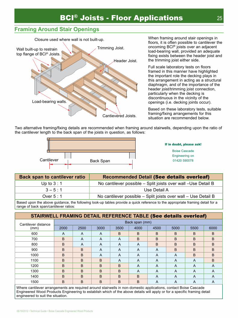
Two alternative framing/fixing details are recommended when framing around stairwells, depending upon the ratio of the cantilever length to the back span of the joists in question, as follows:
Back span to cantilever ratio Recommended Detail (See details overleaf) Up to 3 : 1 No cantilever possible – Split joists over wall –Use Detail B
3 – 5 : 1 Use Detail A Over 5 : 1 No cantilever possible – Split joists over wall – Use Detail B
Based upon the above guidance, the following look-up tables provide a quick reference to the appropriate framing detail for a range of back span/cantilever ratios:
STAIRWELL FRAMING DETAIL REFERENCE TABLE (See details overleaf) Cantilever distance
(mm)Back span (mm)
2000 2500 3000 3500 4000 4500 5000 5500 6000600 A A A B B B B B B700 B A A A B B B B B800 B A A A A B B B B900 B B A A A A B B B
1000 B B A A A A A B B1100 B B B A A A A A B1200 B B B B A A A A A1300 B B B B A A A A A1400 B B B B B A A A A1500 B B B B B A A A A
Where cantilever arrangements are required around stairwells in non-domestic applications, contact Boise Cascade Engineered Wood Products Engineering to establish which of the above details will apply or for a specific framing detail engineered to suit the situation.
When framing around stair openings in floors, it is often possible to cantilever the oncoming BCI® joists over an adjacent load-bearing wall, provided an adequate fixing exists between the header joist and the trimming joist either side.
Full scale laboratory tests on floors framed in this manner have highlighted the important role the decking plays in this arrangement in acting as a structural diaphragm, and of the importance of the header joist/trimming joist connection, particularly when the decking is discontinuous in the vicinity of the openings (i.e. decking joints occur).
Based on these laboratory tests, suitable framing/fixing arrangements for this situation are recommended below.
If in doubt, please ask!
Boise Cascade Engineering on 01420 590078
Framing Around Stair Openings
Ycnn"dwknv/wr"vq"tguvtckp"vqr"hncpig"qh"DEK̶"Lqkuvu0
Enquwtg"wugf"yjgtg"ycnn"ku"pqv"dwknv/wr0
Vtkookpi"Lqkuv0
Jgcfgt"Lqkuv0
Ecpvkgxgtgf"Lqkuvu0
Nqcf/dgctkpi"ycnnu0
Ecpvkngxgt Dcem"Urcp
BCI® Joists - Floor Applications

26
Boise Cascade Engineered Wood Products • Technical Guide • 06/19/2012
BCI® Joists - Floor Applications
BCI® Joists which support loads at the ends of cantilevers may require reinforcement, depending upon the magnitude of the cantilever and the loading imposed. Three reinforcement conditions exist:
1. No reinforcement required – see non load-bearing cantilever detail F14.2. 18mm x 1220m structural panel reinforcement nailed one side of joist.3. 18mm x 1220mm structural panel reinforcement nailed both sides of joist.
Panel reinforcement should be 18mm WBP plywood or OSB to match the full depth of the BCI® Joist. Nail to the BCI® Joist with 3.35x65mm nails at 150mm centres and nail with 4-No 3.35x65mm nails into backer block. When reinforcing both sides, stagger nails to avoid splitting.
To establish which reinforcement detail applies to any particular cantilever arrange ment, contact Boise Cascade Engineered Wood Products Engineering 01420 590078.
Load Bearing External Cantilever Details
822oo"
822oo"
DEK̶"Lqkuv"dnqemkpi"
tgswktgf"hqt"ecpvkngxgt0"
Uvtwevwtcn"rcpgn"enquwtg0"
Ygd"uvkhhgpgt"oc{"dg"tgswktgf"qp"gcej"ukfg"
qh"lqkuvu0"
Uvtwevwtcn"rcpgn"tgkphqtegogpv0"
Dcemgt"dnqem0"
Lqkuvu"hkzgf"vq"jgcfgt"wukpi"5057z87oo"icnxcpkugf"yktg"pcknu"*3/Pq"rgt"hncpig+0
Vqr"hncpig"jcpigt0
Hceg"oqwpv"jcpigt0
XGTUC/NCO̶"Jgcfgt0
XGTUC/NCO̶"Jgcfgt0
Fgvckn"C"*Dcem"urcp1ecpvkngxgt"tcvkq"5/7+0
Lqkuv"hkzgf"vq"jgcfgt"wukpi"vqr"hncpig"qt"hceg"oqwpv"jcpigt0
DEK̶""qt"XGTUC/NCO̶"
Jgcfgt0
Dnqemkpi"dgvyggp"lqkuvu"kh"dnqemyqtm"wr"ctqwpf"lqkuvu"ku"pqv"dwknv0
Lqkuv"urnkv"qxgt"ycnn"cpf"cnkipgf"wukpi"rn{yqqf"urnkeg"rncvgu"qp"qpg"ukfg"qpn{0
Jgcfgt"hkzgf"vq"vtkookpi"lqkuv"wukpi"vqr"hncpig"qt"hceg"oqwpv"jcpigt0
Fgvckn"D"*Dcem"urcp1ecpvkngxgt"tcvkqu"wr"vq"5/3"cpf"qxgt"7/3+0

27
06/19/2012 • Technical Guide • Boise Cascade Engineered Wood Products
406o"o
cz0"
406o"o
cz0"
44z;9oo"okp0"eqpvkpwqwu"nqpikvwfkpcn"dkpfgtu"owuv"dg"vkgf"vq"c"fkciqpcn"dtcegf"cpf"dnqemgf"u{uvgo"cv"qpg"gpf"qh"gcej"dc{0"
Vgorqtct{"fkciqpcn"dtcegu"*okp0"44z;9oo+"pckngf"vq"vjg"hktuv"304o"qh"lqkuvu"cv"pq"oqtg"vjcp"406o"e1e0"Cnvgtpcvkxgn{"hkz"vgorqtct{"qt"rgtocpgpv"ujgcvjkpi"vq"vjg"hktuv"304o"qh"lqkuvu0"
Pckn"cnn"nqpikvwfkpcn"dkpfgtu"cpf"fkciqpcnu"vq"gcej"lqkuv"ykvj"4/Pq"5057z87oo"pcknu0"
Gpfu"qh"ecpvkngxgtu"owuv"dg"ncvgtcnn{"uvcdknkugf"ykvj"vkodgt"dnqemkpi."vgorqtct{"dtcekpi"qt"tko"lqkuv0"DEK̶"Lqkuv"dnqemkpi"ku"tgswktgf"hqt"cnn"ecpvkngxgt"eqpfkvkqpu0"""
Qpeg"rtqrgtn{"dtcegf."hnqqtkpi1egknkpi"ocvgtkcnu"oc{"dg"uvqtgf"wr"vq"207o"jkij"ykvjkp"3o"qh"c"uwrrqtv"*gcej"ukfg"qh""kpvgtkqt"uwrrqtvu+"rtqxkfgf"vjg"nqcf"ku"wpkhqton{"fkuvtkdwvgf"dgvyggp"ugxgtcn"lqkuvu0"
DEK̶"Lqkuv"vqr"hncpigu"owuv"tgockp"uvtckijv"ykvjkp"c"vqngtcpeg"qh"34oo"htqo"vtwg"jqtk¦qpvcn"cnkipogpv"cpf"ykvjkp"c"vqngtcpeg"qh"5oo"htqo"vtwg"xgtvkecn"cnkipogpv0"
Uchgv{"Yctpkpi""FQ"PQV"CNNQY"YQTMGTU"QP"DEK̶"LQKUVU"WPVKN"CNN"DNQEMKPI."JCPIGTU."TKO"LQKUVU"CPF"VGORQTCT["DTCEKPI"CTG"EQORNGVGF"CU"URGEKHKGF"CDQXG0"Ykvjqwv"dtcekpi."ncvgtcn"dwemnkpi"qt"tqnnqxgt"ku"jkijn{"rtqdcdng"wpfgt"nkijv"eqpuvtwevkqp"nqcfu"*g0i0."c"yqtmgt"ykvj"ocvgtkcn"kp"jcpf+0"
FqpÓv"uvcem"dwknfkpi"ocvgtkcnu"qp"wpdtcegf"lqkuvu0"
FqpÓv"ycnm"qp"lqkuv"
wpvkn"rtqrgt"dtcekpi"ku"kp"rnceg0"
"
"
5:z347oo"okp0"vkodgt"dnqemu"qt"DEK̶"dnqemkpi"qxgt"okp0"5"lqkuvu"qt"304o0"
Eqpvkpwqwu"nqpikvwfkpcn"dkpfgt"kpuvcnngf"qxgt"vkodgt"dnqemu0"
Pqvg<""Ugtkqwu"ceekfgpvu"ecp"tguwnv"htqo"kpuwhhkekgpv"cvvgpvkqp"vq"rtqrgt"dtcekpi"fwtkpi"eqpuvtwevkqp0"Ceekfgpvu"ecp"dg"cxqkfgf"wpfgt"pqtocn"eqpfkvkqpu"d{"hqnnqykpi"vjgug"iwkfgnkpgu0"
C"ncvgtcn"tguvtckpv"u{uvgo"owuv"dg"guvcdnkujgf"cv"vjg"gpf"qh"gcej"hnqqt"dc{"vq"rtgxgpv"dwemnkpi"ukfgyc{u"qt"tqnnqxgt0"Vjku"ecp"dg"fqpg"d{"wukpi"vgorqtct{"dtcegu"*ujqyp"dgnqy+"qt"d{"hkzkpi"ujgcvjkpi"qxgt"vjg"hktuv"304o"qh"lqkuvu"cpf"kpuvcnnkpi"vkodgt"dnqemkpi"dgpgcvj0"Cnn"lqkuvu"kp"vjg"hnqqt"dc{"owuv"vjgp"dg"eqppgevgf"dcem"vq"vjku"dtcegf"ugevkqp"d{"yc{"qh"eqpvkpwqwu"nqpikvwfkpcn"dkpfgtu"rtkqt"vq"cnnqykpi"yqtmgtu"qt"rncekpi"eqpuvtwevkqp"nqcfu"qp"vjg"hnqqt0"Kp"nqpi"dc{u."kpuvcnn"cffkvkqpcn"dtcegf"ugevkqpu"pqv"itgcvgt"vjcp"34o"crctv0"
Maximum Man Handling Onsite.241mm Deep Joists
Product kg/m Max Length1 Person
Max Length2 Person
BCI® 4500s 3.12 8.01 16.02BCI® 6000s 3.69 6.77 13.55BCI® 60s 4.23 5.91 11.82BCI® 90s 5.83 4.29 8.58
VERSA-LAM® 38mm 6.04 4.14 8.28VERSA-LAM® 45mm 7.16 3.49 6.98VERSA-LAM® 89mm 14.16 1.77 3.54VERSA-LAM® 133mm 21.15 1.18 2.36
302mm Deep JoistsProduct kg/m Max Length
1 PersonMax Length
2 PersonBCI® 4500s 3.55 7.04 14.08BCI® 6000s 4.12 6.06 12.12BCI® 60s 4.66 5.36 10.72BCI® 90s 6.26 3.99 7.98
VERSA-LAM® 38mm 7.57 3.30 6.60VERSA-LAM® 45mm 8.97 2.79 5.58VERSA-LAM® 89mm 17.74 1.41 2.82VERSA-LAM® 133mm 26.51 0.95 1.89
Temporary Construction Bracing
28
Boise Cascade Engineered Wood Products • Technical Guide • 06/19/2012
BCI® Joists — Hole Location and Sizing
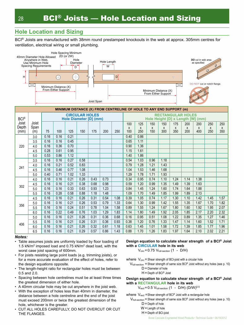
BCI® Joists are manufactured with 38mm round prestamped knockouts in the web at approx. 305mm centres for ventilation, electrical wiring or small plumbing.
Notes:• Table assumes joists are uniformly loaded by floor loading of
1.5 kN/m2 imposed load and 0.75 kN/m2 dead load, with the worst case joist spacing of 600mm.
• For joists resisting large point loads (e.g. trimming joists), or for a more accurate evaluation of the effect of holes, refer to the design equations opposite.
• The length-height ratio for rectangular holes must be between 0.5 and 2.0.
• Spacing between hole centrelines must be at least three times the greatest dimension of either hole.
• A 40mm circular hole may be cut anywhere in the joist web.• With the exception of holes less than 40mm in diameter, the
distance between a hole centreline and the end of the joist must exceed 200mm or twice the greatest dimension of the hole, whichever is the greater.
• CUT ALL HOLES CAREFULLY, DO NOT OVERCUT OR CUT THE FLANGES.
Design equation to calculate shear strength of a BCI® Joist with a CIRCULAR hole in its web Vcirc = 0.75 Vfull-section (1 - D/H)
where Vcirc = Shear strength of BCI-joist with a circular hole Vfull-section = Shear strength of same size BCI® Joist without any holes (see p. 10) D = Diameter of hole H = Depth of BCI® Joist
Design equation to calculate shear strength of a BCI® Joist with a RECTANGULAR hole in its web Vrect = 0.5 Vfull-section (1 - D/H) (D/W)0.5
where Vrect = Shear strength of BCI® Joist with a rectangular hole Vfull-section = Shear strength of same size BCI® Joist without any holes (see p. 10) D = Depth of hole W = Length of hole H = Depth of BCI-joist
DO NOT cut or notch flange.
See roof and floor details, this sheet, for allowed cutting of flange.
DO cut in web area as specified
Hole Location and Sizing
Jqng"Fkcogvgt"
Jqng"Urcekpi"Okpkowo"4F"*qt"4Y+"62oo"Fkcogvgt"Jqng"Cnnqygf"
Cp{yjgtg"kp"Ygd."Wug"Okpkowo"Jqng""
Urcekpi"Tgswktgogpvu"
Okpkowo"Fkuvcpeg"*Z+"Htqo"Gkvjgt"Uwrrqtv"
Jqng"Ngpivj"Y"
J" F"
Okpkowo"Fkuvcpeg"*Z+"Htqo"Gkvjgt"Uwrrqtv"
Lqkuv"Urcp"
F"
MINIMUM DISTANCE (X) FROM CENTRELINE OF HOLE TO ANY END SUPPORT (m)
BCI® Joist
Depth (mm)
Joist Span (m)
CIRCULAR HOLES Hole Diameter [D] (mm)
RECTANGULAR HOLES Hole Height [D] x Length [W] (mm)
75 100 125 150 175 200 250
100x
100
125x
250
150x
150
150x
300
175x
350
200x
200
200x
400
250x
250
250x
350
220
3.03.54.04.55.0
241
3.54.04.55.0
302
4.04.55.05.5
356
4.55.05.56.0
406
5.05.56.06.5
0.16 0.16 0.21 0.40 0.860.16 0.16 0.45 0.65 1.110.16 0.36 0.70 0.90 1.360.28 0.61 0.95 1.15 1.610.53 0.86 1.12 1.40 1.860.16 0.16 0.27 0.58 0.54 1.03 0.96 1.180.16 0.21 0.52 0.83 0.79 1.28 1.21 1.430.16 0.46 0.77 1.08 1.04 1.53 1.46 1.680.40 0.71 1.02 1.33 1.29 1.78 1.71 1.930.16 0.16 0.21 0.26 0.43 0.73 0.34 0.95 0.74 1.10 1.24 1.14 1.380.16 0.16 0.21 0.38 0.68 0.98 0.59 1.20 0.99 1.35 1.49 1.39 1.630.16 0.16 0.33 0.63 0.93 1.23 0.84 1.45 1.24 1.60 1.74 1.64 1.880.16 0.28 0.58 0.88 1.18 1.48 1.09 1.70 1.49 1.85 1.99 1.89 2.130.16 0.16 0.21 0.26 0.31 0.54 1.08 0.39 1.05 0.74 1.17 1.30 1.10 1.42 1.45 1.570.16 0.16 0.21 0.26 0.53 0.79 1.33 0.64 1.30 0.99 1.42 1.55 1.35 1.67 1.70 1.820.16 0.16 0.24 0.51 0.78 1.04 1.58 0.89 1.55 1.24 1.67 1.80 1.60 1.92 1.95 2.070.16 0.22 0.49 0.76 1.03 1.29 1.83 1.14 1.80 1.49 1.92 2.05 1.85 2.17 2.20 2.320.16 0.16 0.21 0.26 0.31 0.36 0.68 0.16 0.95 0.51 1.08 1.22 0.89 1.35 1.27 1.460.16 0.16 0.21 0.26 0.31 0.36 0.93 0.38 1.20 0.76 1.33 1.47 1.14 1.60 1.52 1.710.16 0.16 0.21 0.26 0.32 0.61 1.18 0.63 1.45 1.01 1.58 1.72 1.39 1.85 1.77 1.960.16 0.16 0.21 0.29 0.57 0.86 1.43 0.88 1.70 1.26 1.83 1.97 1.64 2.10 2.02 2.21

29
06/19/2012 • Technical Guide • Boise Cascade Engineered Wood Products
Ground Floor Joist Design
Protection Against Ground Moisture
Insulation
Boise Cascade Engineered Wood Products recommends that ground loor joists are designed to improved service-ability levels to provide a loor with a similar ‘feel’ to an in situ or precast concrete loor construction, but this decision is at the discretion of the Building Designer. Ground loor joists are considered to be in a service class 2 environment and should be designed using the service class 2 properties given in the table on page 10.
Due to the lack of a plasterboard diaphragm on the underside of the joists, it may be necessary to install a bracing system to the bottom lange of the BCI® Joists where they are continuous over internal supports, and consequently the bottom lange will be subject to a compression force.
The ground cover layer should be chosen from one of the following options:
a) 50mm of inert sand, gravel or concrete on 300 micron (1200g) polythene (1000g if PIFA branded) lapped and turned up at the edges, on 25mm sand blinding
b) 100mm concrete on well consolidated hardcore
c) 50mm concrete on polyethylene membrane on 50mm sand blinding
On sloping sites where external ground levels are higher than internal, the internal ground cover should fall to a suitable drainage outlet.
Under loor ventilation should be in accordance with The Building Regulations and ventilator manufacturer speciications. A minimum clear height of 150mm should be provided between the underside of the BCI® Joists and the internal ground cover.
Where protection is required against Radon gas or other ground gases specialist advice should be sought.
U values and insulation requirements will vary depending on the loor size and must be calculated independently for each loor construction.Insulation can be installed in ground loor situations using three methods:1) Use a rigid insulation without additional support by
sitting the insulation directly on the BCI® Joist bottom langes
2) Support the insulation between the joists on either a galvanised wire mesh or a breather membrane
3) Fix ibreboard or rigid mesh to the BCI® Joist bottom langes and place the insulation on top
Disabled AccessAll new dwellings require a level threshold to provide easy access for the disabled. Refer to DETR –‘Accessible thresholds in new housing; Guidance for house builders and designers’, or TRADA Technology – ‘Level Thresholds: the timber loor solution.’
qt"Icnxcpkugf"yktg"oguj"rncuvke"oguj"qt"dtgcvjgt"ogodtcpg" Tkikf"oguj"qt"
hkdtgdqctf0""
Tkikf"Kpuwncvkqp"ykvjqwv"oguj0"
Okp0"47oo"
Okp0"372oo"
FRE"
Okp0"97oo"vq"FRE"
Gzvgtpcn"Ycnn0" Gzvgtpcn"Ycnn0"Unggrgt"Ycnn0"
47oo"ckt"icr0"
Okp0"372"
Okp0"372oo"
DEK"Lqkuv"
FRE"
Kpuwncvg"gfig"icr0"
Kpuwncvkqp"pqv"ujqyp"hqt"enctkv{0"
Lqkuvu"oc{"dg"dwknv"kp"qt"uwrrqtvgf"kp"ocuqpt{"jcpigtu0"
Itqwpf"eqxgt"nc{gtu"ejqugp"htqo"qrvkqpu"nkuvgf0"
BCI® Joists — Ground Floor Construction

30
Boise Cascade Engineered Wood Products • Technical Guide • 06/19/2012
BCI® Joists — Fire, Sound and Air Leakage
BCI® Joist Floor Construction to Meet the Requirements of Parts B, E and L1 (Fire, Sound and Air Leakage) of The Building RegulationsRecent changes to Part E of The Building Regulations (Resistance to the passage of sound – 2003 Edition) coupled with earlier changes to Part L1 (Conservation of fuel and power – 2002 Edition) together with the continuing need to meet the requirements of Part B (Fire safety) mean that when considering prospective loor constructions for a project it is necessary to select appropriate loor deck, joists and ceiling products that result in a loor system that meets all regulatory requirements.The RequirementsSound ResistanceThe 2003 edition of Approved Document E sets improved sound insulation standards for loors within dwellings and between dwellings, and their junctions with separating walls. In addition, separating loors between dwellings will re-quire pre-completion testing if not constructed in accordance with Robust details[A]. The sound insulation performance that loors must achieve is shown in the table below.
Sound Resistance Required for Floors
Floor Type
Sound Resistance RequiredPre-completion
testing required? Boise Cascade SolutionAirbornedB min.
ImpactL’nT,w dB max.
Intermediate Rw ≥40[B] - NoSee below for intermediate BCI®Joist loors that meet the requirement of Building Regulation E2
SeparatingD nT,w + Ctr
≥45[C] ≤62[C]
No – if loor constructed in accordance with Robust details.Yes – if loor not con-structed in accordance with Robust details
See detail below for I-joist separating loor that conforms to Robust details. Note that both loor and separating wall must be compatible Robust details to avoid pre-completion testing. Refer to ‘Robust details Part – E Resistance to the passage of sound,’ January 2005
[A] The use of Robust details by builders is subject to the terms and conditions set out by Robust Details Limited.[B] The requirement is for a laboratory sound reduction of 40dB.[C] The requirement is for on site sound reduction, met by either complying with Robust details or pre-completion testing.
Compliance with the sound resistance requirements for BCI® Joist loors is provided by laboratory sound tests in re-spect of intermediate loors, and adherence to Robust details in respect of separating loors.Fire ResistanceApproved Document B to The Building Regulations requires loors to achieve the periods of ire resistance noted in the table below. Fire resistance is usually deined in three parts: structure, integrity and insulation. Broad deinitions are as follows: Structure – the construction shall not fail during the required resistance period. Integrity – the construction shall not allow combustion gases or smoke to pass through during the required resistance period. Insulation – the construction shall not allow excessive heat to pass through during the required resistance period.
Fire Resistance Periods for FloorsBuilding Type Floor Type Required Resistance (Min)
House - detached, semi, terrace, not more than three storeys Intermediate[1] [2] 30
Flats Separating 60
Maisonettes Intermediate (within a maisonette)Separating (between maisonettes)
3060
For all other building uses refer to Approved Document B[1] The intermediate loor in a 2-storey house may have a modiied 1/2–hour ire resistance; 30 minute structure, 15 minutes integrity and
15 minutes insulation.[2] The intermediate loor above a basement should have at least 1-hour ire resistance.
The walls between semi-detached or terraced houses, and between lats, are separating walls and should have at least 1-hour ire resistance.Compliance with the ire resistance requirements for BCI® Joist loors is provided by the results of full-scale structural ire tests.

31
06/19/2012 • Technical Guide • Boise Cascade Engineered Wood Products
BCI® Joist Floor Construction to Meet the Requirements of Parts B, E and L1 (Fire, Sound and Air Leakage) of The Building Regulations (continued)
The Requirements (continued)Air LeakageApproved Document L1 (2002 Edition) requires buildings to limit unwanted air leakage, and in the absence of perfor-mance criteria refers to the use of Robust Details contained in the publication ‘Limiting thermal bridging and air leak-age: Robust construction details for dwellings and similar buildings’. The primary area affected with regard to loors is in their junctions with external walls and in particular masonry walls. Timber frame loors and walls remain largely unaffected. To ensure compliance with the approved Document, the Robust Details show joists supported at external walls in masonry hangers. Alternatively, a construction detail that involves building joists into the wall and sealing all air paths with silicone sealant is accepted by Regulatory Authorities subject to good site workmanship. Addition-ally, proprietary details that can be shown by laboratory tests to meet or exceed the air leakage performance of the silicone sealant detail may also be used.Compliance with the air leakage requirements for BCI® Joist loors is provided by the use of either a proprietary detail (Proprietary End Cap), the silicone sealant detail, or by supporting joists in masonry hangers.
Meeting the RequirementsThe following details showing loor constructions and loor/wall junctions have been prepared to meet the current Building Regulation requirements with regard to Part B, Part E and Part L1. Each detail gives reference to relevant test data or Robust Details in validation of the performance.
Intermediate loorsGeneral Floor ConstructionThe diagrams and table below specify intermediate loor constructions that meet the Building Regulation require-ments for Sound and Fire.
Intermediate Floor ConstructionsSection Through Floor Layer and Material Justiication
In-1
Hnqqt"fgem0"
DEK̶"Lqkuvu0"
Egknkpi"1"Cduqtdgpv"Nc{gt0"
Floor Deck:22mm P5 Chipboard
Sound:- Lab tests in accordance with BS EN ISO 140-3:1995, and expert sound consultant assessment of results.
Fire:- ½ hour structural ire test in accordance with BS 476-21:1987 and expert ire consultant assessment of results.
Joist:Any BCI® Joist 241mm or deeper at 600mm centres
Ceiling/Absorbent Layer:15mm Type 1 plasterboard[1]
12.5mm Type 1 plasterboard +3mm skim[1]
12.5mm Type 5 ire resisting plasterboard[1]
(all inclusive 1 downlighter per 1.5m2 loor area
In-2
Hnqqt"fgem0"
Egknkpi"1"Cduqtdgpv"Nc{gt0"
DEK̶"Lqkuvu0"
Floor Deck:22mm P5 Chipboard
Sound:- Lab tests in accordance with BS EN ISO 140-3:1995, and expert sound consultant assessment of results.
Fire:- ½ hour structural ire test in accordance with BS 476-21:1987 and expert ire consultant assessment of results.
Joist:Any BCI® Joist 241mm or deeper at 400mm centres or greater
Ceiling/Absorbent Layer:15mm Type 1 plasterboard[1] +1mm skim12.5mm Type 1 plasterboard[1] +4mm skim12.5mm Type 5 ire resisting plasterboard[1] +1mm skim(all inclusive 1 downlighter per 1.5m2 loor area
In-3
Hnqqt"fgem0"
Egknkpi"1"Cduqtdgpv"Nc{gt0"
DEK̶"Lqkuvu0"
Floor Deck:22mm P5 Chipboard or 22mm cement bonded particle board, or any board with a surface mass of 15kg/m2
Sound:- Approved Document E clause 5.23 deemed to satisfy construction.
Fire:- ½ hour structural ire test in accordance with BS 476-21:1987 and expert ire consultant assessment of results.
Joist:Any BCI® Joist at any centres
Ceiling/Absorbent Layer:15mm Type 1 plasterboard[1]
12.5mm Type 1 plasterboard[1] +3mm skim12.5mm Type 5 ire resisting plasterboard[1]
plus100mm mineral wool insulation min density 10kg/m3
[1] Plasterboard to have a minimum surface mass of 10kg/m2.
BCI® Joists — Fire, Sound and Air Leakage
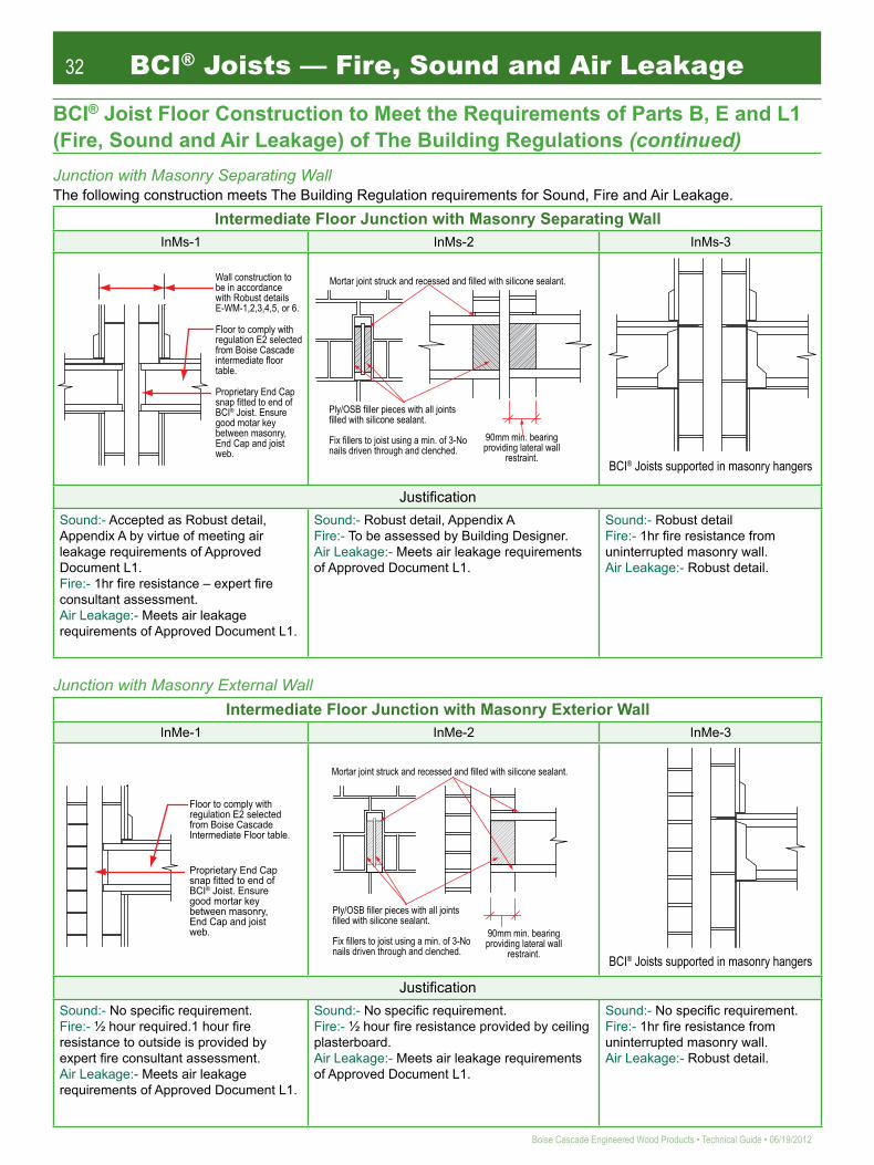
32
Boise Cascade Engineered Wood Products • Technical Guide • 06/19/2012
BCI® Joists — Fire, Sound and Air Leakage
BCI® Joist Floor Construction to Meet the Requirements of Parts B, E and L1 (Fire, Sound and Air Leakage) of The Building Regulations (continued)Junction with Masonry Separating WallThe following construction meets The Building Regulation requirements for Sound, Fire and Air Leakage.
Intermediate Floor Junction with Masonry Separating WallInMs-1 InMs-2 InMs-3
Rtqrtkgvct{"Gpf"Ecr"upcr"hkvvgf"vq"gpf"qh"DEK̶"Lqkuv0"Gpuwtg"iqqf"oqvct"mg{"dgvyggp"ocuqpt{."Gpf"Ecr"cpf"lqkuv"ygd0
Hnqqt"vq"eqorn{"ykvj"tgiwncvkqp"G4"ugngevgf"htqo"Dqkug"Ecuecfg"kpvgtogfkcvg"hnqqt"vcdng0
Ycnn"eqpuvtwevkqp"vq"dg"kp"ceeqtfcpeg"ykvj"Tqdwuv"fgvcknu"G/YO/3.4.5.6.7."qt"80
Oqtvct"lqkpv"uvtwem"cpf"tgeguugf"cpf"hknngf"ykvj"uknkeqpg"ugcncpv0"
;2oo"okp0"dgctkpi"rtqxkfkpi"ncvgtcn"ycnn"
tguvtckpv0"
Rn{1QUD"hknngt"rkgegu"ykvj"cnn"lqkpvu"hknngf"ykvj"uknkeqpg"ugcncpv0""Hkz"hknngtu"vq"lqkuv"wukpi"c"okp0"qh"5/Pq"pcknu"ftkxgp"vjtqwij"cpf"engpejgf0"
DEK̶"Lqkuvu"uwrrqtvgf"kp"ocuqpt{"jcpigtu"
JustiicationSound:- Accepted as Robust detail, Appendix A by virtue of meeting air leakage requirements of Approved Document L1.Fire:- 1hr ire resistance – expert ire consultant assessment.Air Leakage:- Meets air leakage requirements of Approved Document L1.
Sound:- Robust detail, Appendix AFire:- To be assessed by Building Designer.Air Leakage:- Meets air leakage requirements of Approved Document L1.
Sound:- Robust detailFire:- 1hr ire resistance from uninterrupted masonry wall.Air Leakage:- Robust detail.
Junction with Masonry External WallIntermediate Floor Junction with Masonry Exterior Wall
InMe-1 InMe-2 InMe-3
Rtqrtkgvct{"Gpf"Ecr"upcr"hkvvgf"vq"gpf"qh"DEK̶"Lqkuv0"Gpuwtg"iqqf"oqtvct"mg{"dgvyggp"ocuqpt{."Gpf"Ecr"cpf"lqkuv"ygd0
Hnqqt"vq"eqorn{"ykvj"tgiwncvkqp"G4"ugngevgf"htqo"Dqkug"Ecuecfg""Kpvgtogfkcvg"Hnqqt"vcdng0
Oqtvct"lqkpv"uvtwem"cpf"tgeguugf"cpf"hknngf"ykvj"uknkeqpg"ugcncpv0"
;2oo"okp0"dgctkpi"rtqxkfkpi"ncvgtcn"ycnn"
tguvtckpv0"
Rn{1QUD"hknngt"rkgegu"ykvj"cnn"lqkpvu"hknngf"ykvj"uknkeqpg"ugcncpv0""Hkz"hknngtu"vq"lqkuv"wukpi"c"okp0"qh"5/Pq"pcknu"ftkxgp"vjtqwij"cpf"engpejgf0"
DEK̶"Lqkuvu"uwrrqtvgf"kp"ocuqpt{"jcpigtu"
JustiicationSound:- No speciic requirement.Fire:- ½ hour required.1 hour ire resistance to outside is provided by expert ire consultant assessment.Air Leakage:- Meets air leakage requirements of Approved Document L1.
Sound:- No speciic requirement.Fire:- ½ hour ire resistance provided by ceiling plasterboard.Air Leakage:- Meets air leakage requirements of Approved Document L1.
Sound:- No speciic requirement.Fire:- 1hr ire resistance from uninterrupted masonry wall.Air Leakage:- Robust detail.

33
06/19/2012 • Technical Guide • Boise Cascade Engineered Wood Products
BCI® Joist Floor Construction to Meet the Requirements of Parts B, E and L1 (Fire, Sound and Air Leakage) of The Building Regulations (continued)Junction with Timber Frame Separating WallThe following construction meets The Building Regulation requirements for Sound, Fire and Air Leakage.
Intermediate Floor Junction with Timber Frame Separating Wall
Enqug"urcegu"dgvyggp"DEK̶"Lqkuvu"ykvj"hwnn"fgrvj"XGTUC/NCO̶"Tko"dnqemkpi"cpf"rn{"ygd"hknngtu"yjgtg"lqkuvu"ctg"cv"tkijv"cpingu"vq"ycnn0
Hnqqt"vq"eqorn{"ykvj"tgiwncvkqp"G4"ugngevgf"htqo"Dqkug"Ecuecfg"Kpvgtogfkcvg"Hnqqt"vcdng0
Ycnn"eqpuvtwevkqp"vq"dg"kp"ceeqtfcpeg"ykvj"Tqdwuv"fgvcknu"G/YV/3"qt"G/YV/40
Hnqqt"fgemkpi"oc{"twp"wpfgt"uqng"rncvgu0"
Ugcn"cnn"rgtkogvgt"lqkpvu"ykvj"vcrg"qt"ecwnm"ykvj"ugcncpv0
XGTUC/NCO̶"Tko"dqctfu0
JustiicationSound:- Robust detail Fire:- TRADA Technology ‘Timber frame construction Chapter 5’
Air leakage:- Meets air leakage requirements of Approved Document L1
Junction with Timber Frame External WallThe following construction meets The Building Regulation requirements for Sound, Fire and Air Leakage.
Intermediate Floor Junction with Timber Frame External Wall
""
Kpuwncvkqp0
RXE"icumgv"qt"dgcf"qh"ugcncpv0"
JustiicationSound:- No speciic requirement Fire:- Generic timber frame detail Air leakage:- Robust Detail
BCI® Joists — Fire, Sound and Air Leakage
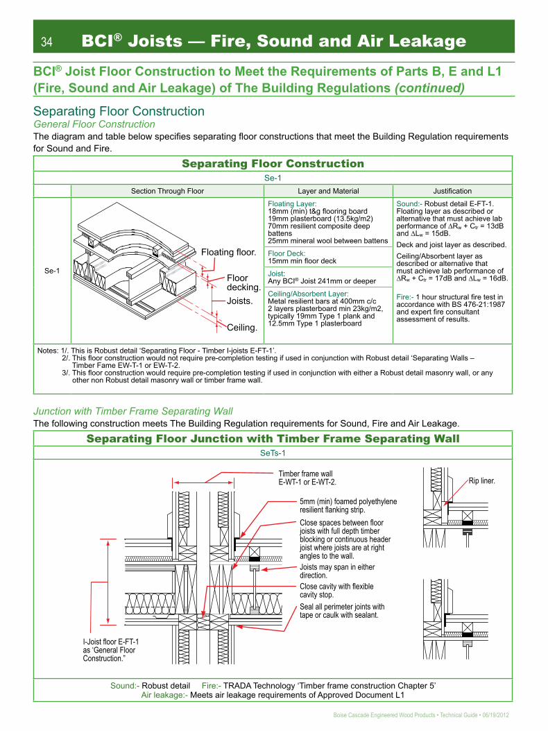
34
Boise Cascade Engineered Wood Products • Technical Guide • 06/19/2012
BCI® Joists — Fire, Sound and Air Leakage
BCI® Joist Floor Construction to Meet the Requirements of Parts B, E and L1 (Fire, Sound and Air Leakage) of The Building Regulations (continued)
Separating Floor ConstructionGeneral Floor ConstructionThe diagram and table below speciies separating loor constructions that meet the Building Regulation requirements for Sound and Fire.
Separating Floor ConstructionSe-1
Section Through Floor Layer and Material Justiication
Se-1
Hnqcvkpi"hnqqt0"
Hnqqt""fgemkpi0Lqkuvu0"
Egknkpi0"
Floating Layer:18mm (min) t&g looring board19mm plasterboard (13.5kg/m2)70mm resilient composite deep battens25mm mineral wool between battens
Sound:- Robust detail E-FT-1. Floating layer as described or alternative that must achieve lab performance of ∆Rw + Ctr = 13dB and ∆Lw = 15dB.Deck and joist layer as described.Ceiling/Absorbent layer as described or alternative that must achieve lab performance of ∆Rw + Ctr = 17dB and ∆Lw = 16dB.
Fire:- 1 hour structural ire test in accordance with BS 476-21:1987 and expert ire consultant assessment of results.
Floor Deck:15mm min loor deck
Joist:Any BCI® Joist 241mm or deeper
Ceiling/Absorbent Layer:Metal resilient bars at 400mm c/c 2 layers plasterboard min 23kg/m2, typically 19mm Type 1 plank and 12.5mm Type 1 plasterboard
Notes: 1/. This is Robust detail ‘Separating Floor - Timber I-joists E-FT-1’. 2/. This loor construction would not require pre-completion testing if used in conjunction with Robust detail ‘Separating Walls – Timber Fame EW-T-1 or EW-T-2. 3/. This loor construction would require pre-completion testing if used in conjunction with either a Robust detail masonry wall, or any other non Robust detail masonry wall or timber frame wall.
Junction with Timber Frame Separating WallThe following construction meets The Building Regulation requirements for Sound, Fire and Air Leakage.
Separating Floor Junction with Timber Frame Separating WallSeTs-1
""
""
Tkr"nkpgt0"
K/Lqkuv"hnqqt"G/HV/3"cu"ÒIgpgtcn"Hnqqt"Eqpuvtwevkqp0Ñ"
7oo"*okp+"hqcogf"rqn{gvj{ngpg"tguknkgpv"hncpmkpi"uvtkr0"
Vkodgt"htcog"ycnn"G/YV/3"qt"G/YV/40"
Enqug"urcegu"dgvyggp"hnqqt"lqkuvu"ykvj"hwnn"fgrvj"vkodgt"dnqemkpi"qt"eqpvkpwqwu"jgcfgt"lqkuv"yjgtg"lqkuvu"ctg"cv"tkijv"cpingu"vq"vjg"ycnn0"Lqkuvu"oc{"urcp"kp"gkvjgt"fktgevkqp0"Enqug"ecxkv{"ykvj"hngzkdng"ecxkv{"uvqr0"Ugcn"cnn"rgtkogvgt"lqkpvu"ykvj"vcrg"qt"ecwnm"ykvj"ugcncpv0"
Sound:- Robust detail Fire:- TRADA Technology ‘Timber frame construction Chapter 5’ Air leakage:- Meets air leakage requirements of Approved Document L1

35
06/19/2012 • Technical Guide • Boise Cascade Engineered Wood Products
BCI® Joist Floor Construction to Meet the Requirements of Parts B, E and L1 (Fire, Sound and Air Leakage) of The Building Regulations (continued)Junction with Timber Frame External WallThe following construction meets The Building Regulation requirements for Sound, Fire and Air Leakage.
Separating Floor Junction with Timber Frame External WallSeTe-1
Tkr"nkpgt0"
Enqug"urcegu"dgvyggp"hnqqt"lqkuvu"ykvj"eqpvkpwqwu"jgcfgt"lqkuv"yjgtg"lqkuvu"ctg"cv"tkijv"cpingu"vq"ycnn0"
Ocuqpt{"qwvgt"ngch0"Gzvgtpcn"ycnn"ecxkv{"*okp0"72oo+0"Vyq"nc{gtu"i{ruwo/dcugf"dqctf"pqokpcn":mi1o4"gcej"nc{gt"
7oo"*okp0+"hqcogf"rqn{gvj{ngpg"tgukngpv"hncpmkpi"uvtkr0"Enqug"ecxkv{"ykvj"hngzkdng"ecxkv{"uvqr0"
Lqkuvu"oc{"urcp"kp"gkvjgt"fktgevkqp0"
Ugcn"cnn"rgtkogvgt"lqkpvu"ykvj"vcrg"qt"ecwnm"ykvj"ugcncpv0"
Sound:- Robust detail E-FT-1 Fire:- TRADA Technology ‘Timber frame construction Chapter 5 Air leakage:- Robust detail
Junction with Masonry WallsThere is currently no authoritative guidance on satisfying the requirements of Approved Document E (Sound) with regard to I-joist separating loors and their junctions with masonry walls. Generic details are shown below, but spe-cialist acoustic advice should be sought where this type of construction is proposed. Pre-completion sound testing will be required.
Separating Floor Junction with Masonry Wall
Ocuqpt{"jcpigtu"hkzgf"kp"ceeqtfcpeg"ykvj"ocpwhcevwtgtÓu"kpuvtwevkqpu"qt"wug"crrtqxgf"dwknv/kp"fgvckn"*ugg"H39+0"
Tguknkgpv"dct0"
Egknkpi"nkpkpi0"
Cduqtdgpv"kpuwncvkqp0"
Cduqtdgpv"kpuwncvkqp0"
Tguknkgpv"dcvvgp0"
Kuqncvkqp"uvtkr0"
Tguknkgpv"okpgtcn"yqqn"nc{gt0"
Rgtkogvgt"pqiikpi0"
Generic detail only, seek specialist advise for sound reduction performance.
BCI® Joists — Fire, Sound and Air Leakage

36
Boise Cascade Engineered Wood Products • Technical Guide • 06/19/2012
BCI® Joists — Roof Applications
BCI® Joists can be used to create open roof voids in buildings by acting as free-spanning rafters between a ridge beam at the roof apex and the wallplate at eaves level.
BCI® Joist suppliers involved in roof applications assume a role similar to that of the trussed rafter designer, as outlined in BS5268-3:1998, clauses 6, 7 and 11. The Building Designer remains responsible for the roof design, including specification of all holding down fixings at support positions, and the stability and wind bracing systems, unless otherwise agreed or a roof designer has been employed. I-Joist roofs should be braced, or arranged, to form a coherent structure. The bracing can be in the form of a structural diaphragm (sarking) or triangulating members, the specification of which remains the responsibility of the Building Designer.
BCI® Joists are designed for roof applications using the principles of BS5268-2:2002 and the joist properties contained in BBA Certificate 99/3620. In general, it can be assumed that well-ventilated roofs in the UK will achieve a Service Class 2 moisture condition. Uniformly distributed dead and imposed loads will be assumed across the whole roof unless otherwise directed. For small buildings, as detailed in BS6399-3, imposed loads (snow loading) will generally be taken as 0.75 kN/m2 (measured on plan) up to pitches of 30o, reducing linearly to zero at 60o pitch, unless specific guidance in the aforementioned code would suggest alternative imposed roof loadings may apply. Snow loading will be assumed to be of medium term duration. Dead loads from coverings may be taken from the schedule of standard tile weights tabulated to the right.
In practice, roof dead loads are often categorised as either light, standard or heavy, these being 0.434kN/m2, 0.685kN/m2 or 0.880kN/m2, representing fibre-cement, concrete interlocking and plain concrete-type tiles, respectively. These values are measured along the rafter slope and include an allowance of 0.11kN/m2 for felt, battens and rafter self weight.
Since ceiling finishes may often be directly applied to the underside of BCI® Joists used to create open roof voids, Boise Cascade Engineered Wood Products Engineering recom mends that BCI® rafters be designed with a 0.25 kN/m2 ceiling dead load, including further allowance for self weight of the rafter and a deflection limit of 0.3% x span under the total (dead + imposed) load. On this basis, maximum rafter spans are shown on pages 37 and 38 for a range of roof pitches for either light, standard or heavy roof coverings.
Tile Manufacturer and Product
Weight on Slope (inc. SW allowance
of 110 N/m2)Marley Modern 659 N/m2
Marley Plain 973 N/m2
Marley Bold Roll 630 N/m2
Redland Cambrian 306 N/m2
Redland Renown 565 N/m2
Redland Rosemary 767 N/m2
Thatching (305mm Thick) 518 N/m2
Roof Design Criteria
Schedule of Roof Covering Dead Loads

37
06/19/2012 • Technical Guide • Boise Cascade Engineered Wood Products
Roof Rafter Span Tables
Design Notes :1 - All spans quoted are ‘engineering spans’ measured on plan between centres of bearings.2 - Linear interpolation may be used for intermediate roof pitches between those tabulated.3 - Spans assume rafters are restrained via battens at centres no greater than 400mm.4 - Dead loads quoted are measured on slope and allow for standard fibre-cement, concrete interlocking and plain concrete tiles
respectively plus felt, battens, rafter self-weight and plasterboard ceiling. A ceiling dead load allowance of 0.25kN/m2 has been assumed.
5 - Imposed load assumed is 0.75kN/m2 (measured on plan) up to 30o pitch, reducing linearly thereafter to zero at 60o pitch.6 - All spans quoted relate to medium-term load duration. Refer to Boise Cascade Engineered Wood Products Engineering for
long-term loading conditions.7 - Deflection limited to 0.3% of the span.
Joist Depth
Joist Series
Maximum Rafter Spans (m) @ 400mm c/c (Medium duration loading, k3 = 1.25)
Lightweight Tile Loading(0.434kN/m2 dead + 0.75kN/m2 imposed)
Standard Tile Loading(0.685kN/m2 dead + 0.75kN/m2 imposed)
Heavy Tile Loading(0.880kN/m2 dead + 0.75kN/m2 imposed)
15o 22.5o 30o 37.5o 45o 15o 22.5o 30o 37.5o 45o 15o 22.5o 30o 37.5o 45o
4500s
60s
90s
4500s
6000s
60s
90s
4500s
6000s
60s
90s
6000s
60s
90s
6000s
60s
90s
241 mm
302mm
356mm
406mm
4.80 4.68 4.51 4.30 4.02 4.48 4.37 4.21 4.00 3.74 4.28 4.17 4.02 3.82 3.57
5.56 5.45 5.28 5.11 4.78 5.24 5.13 4.97 4.73 4.42 5.04 4.93 4.75 4.51 4.21
6.39 6.26 6.07 6.02 5.62 6.02 5.89 5.71 5.55 5.18 5.79 5.66 5.48 5.28 4.93
5.17 5.06 4.91 4.68 4.38 4.87 4.75 4.57 4.34 4.06 4.65 4.53 4.36 4.15 3.87
5.42 5.31 5.15 4.96 4.64 5.12 5.01 4.84 4.59 4.29 4.92 4.79 4.61 4.38 4.10
5.89 5.77 5.60 5.47 5.12 5.55 5.43 5.26 5.05 4.72 5.33 5.22 5.05 4.82 4.50
6.81 6.67 6.48 6.49 6.07 6.42 6.28 6.09 5.97 5.58 6.17 6.03 5.84 5.68 5.30
6.14 6.01 5.83 5.74 5.37 5.80 5.67 5.49 5.30 4.95 5.57 5.45 5.27 5.05 4.72
6.45 6.31 6.12 6.08 5.68 6.08 5.95 5.76 5.61 5.23 5.85 5.72 5.53 5.34 4.98
7.06 6.92 6.71 6.72 6.31 6.66 6.52 6.31 6.22 5.80 6.40 6.26 6.06 5.92 5.52
8.13 7.97 7.73 7.76 7.43 7.67 7.51 7.27 7.21 6.81 7.37 7.21 6.97 6.89 6.46
7.29 7.14 6.93 6.94 6.54 6.88 6.73 6.52 6.45 6.02 6.62 6.47 6.26 6.13 5.72
8.04 7.87 7.63 7.65 7.31 7.58 7.42 7.18 7.11 6.71 7.29 7.13 6.90 6.80 6.37
9.23 9.02 8.78 8.80 8.57 8.71 8.52 8.25 8.18 7.83 8.36 8.18 7.92 7.82 7.42
8.05 7.88 7.65 7.66 7.32 7.60 7.43 7.20 7.12 6.72 7.31 7.14 6.91 6.81 6.38
8.90 8.72 8.46 8.47 8.21 8.40 8.22 7.96 7.88 7.51 8.08 7.90 7.64 7.53 7.13
10.19 9.99 9.69 9.71 9.57 9.61 9.41 9.11 9.03 8.73 9.24 9.03 8.74 8.63 8.26
BCI® Joists — Roof Applications
220mm

38
Boise Cascade Engineered Wood Products • Technical Guide • 06/19/2012
BCI® Joists — Roof Applications
Roof Rafter Span Tables
Design Notes :1 - All spans quoted are ‘engineering spans’ measured on plan between centres of bearings.2 - Linear interpolation may be used for intermediate roof pitches between those tabulated.3 - Spans assume rafters are restrained via battens at centres no greater than 400mm.4 - Dead loads quoted are measured on slope and allow for standard fibre-cement, concrete interlocking and plain concrete tiles
respectively plus felt, battens, rafter self-weight and plasterboard ceiling. A ceiling dead load allowance of 0.25kN/m2 has been assumed.
5 - Imposed load assumed is 0.75kN/m2 (measured on plan) up to 30o pitch, reducing linearly thereafter to zero at 60o pitch.6 - All spans quoted relate to medium-term load duration. Refer to Boise Cascade Engineered Wood Products Engineering for
long-term loading conditions.7 - Deflection limited to 0.3% of the span.
Joist Depth
Joist Series
Maximum Rafter Spans (m) @ 600mm c/c (Medium duration loading, k3 = 1.25)
Lightweight Tile Loading(0.434kN/m2 dead + 0.75kN/m2 imposed)
Standard Tile Loading(0.685kN/m2 dead + 0.75kN/m2 imposed)
Heavy Tile Loading(0.880kN/m2 dead + 0.75kN/m2 imposed)
15o 22.5o 30o 37.5o 45o 15o 22.5o 30o 37.5o 45o 15o 22.5o 30o 37.5o 45o
4500s
60s
90s
4500s
6000s
60s
90s
4500s
6000s
60s
90s
6000s
60s
90s
6000s
60s
90s
241 mm
302mm
356mm
406mm
220mm
4.17 4.09 3.97 3.92 3.66 3.93 3.85 3.73 3.61 3.38 3.77 3.69 3.57 3.44 3.21
4.81 4.71 4.57 4.59 4.33 4.53 4.44 4.30 4.25 3.97 4.35 4.26 4.12 4.04 3.77
5.52 5.41 5.25 5.27 5.07 5.20 5.09 4.93 4.90 4.64 4.99 4.88 4.73 4.67 4.39
4.47 4.38 4.25 4.25 3.98 4.22 4.13 4.00 3.91 3.66 4.05 3.96 3.83 3.72 3.48
4.69 4.60 4.46 4.48 4.21 4.42 4.33 4.19 4.13 3.86 4.25 4.15 4.02 3.93 3.67
5.09 4.99 4.85 4.86 4.62 4.79 4.69 4.55 4.51 4.23 4.60 4.50 4.36 4.30 4.02
5.88 5.76 5.60 5.62 5.46 5.53 5.42 5.25 5.22 4.98 5.31 5.20 5.03 4.98 4.71
5.32 5.21 5.06 5.07 4.85 5.01 4.91 4.75 4.71 4.44 4.82 4.71 4.56 4.50 4.21
5.58 5.47 5.31 5.32 5.12 5.26 5.15 4.99 4.95 4.69 5.05 4.94 4.78 4.72 4.45
6.11 5.99 5.81 5.83 5.68 5.76 5.64 5.46 5.42 5.18 5.53 5.41 5.24 5.17 4.91
7.02 6.89 6.69 6.72 6.64 6.61 6.48 6.28 6.23 6.05 6.35 6.21 6.02 5.95 5.72
6.32 6.19 6.00 6.02 5.88 5.95 5.83 5.65 5.60 5.37 5.72 5.60 5.42 5.35 5.09
6.96 6.82 6.61 6.64 6.55 6.56 6.42 6.22 6.17 5.97 6.30 6.16 5.97 5.89 5.65
7.98 7.82 7.59 7.63 7.54 7.51 7.36 7.13 7.08 6.91 7.21 7.06 6.83 6.76 6.56
6.97 6.83 6.63 6.65 6.56 6.58 6.44 6.23 6.18 5.99 6.32 6.18 5.98 5.90 5.67
7.71 7.56 7.33 7.35 7.26 7.27 7.12 6.89 6.83 6.67 6.99 6.83 6.61 6.53 6.32
8.81 8.64 8.38 8.42 8.32 8.30 8.13 7.88 7.82 7.63 7.97 7.79 7.55 7.46 7.24
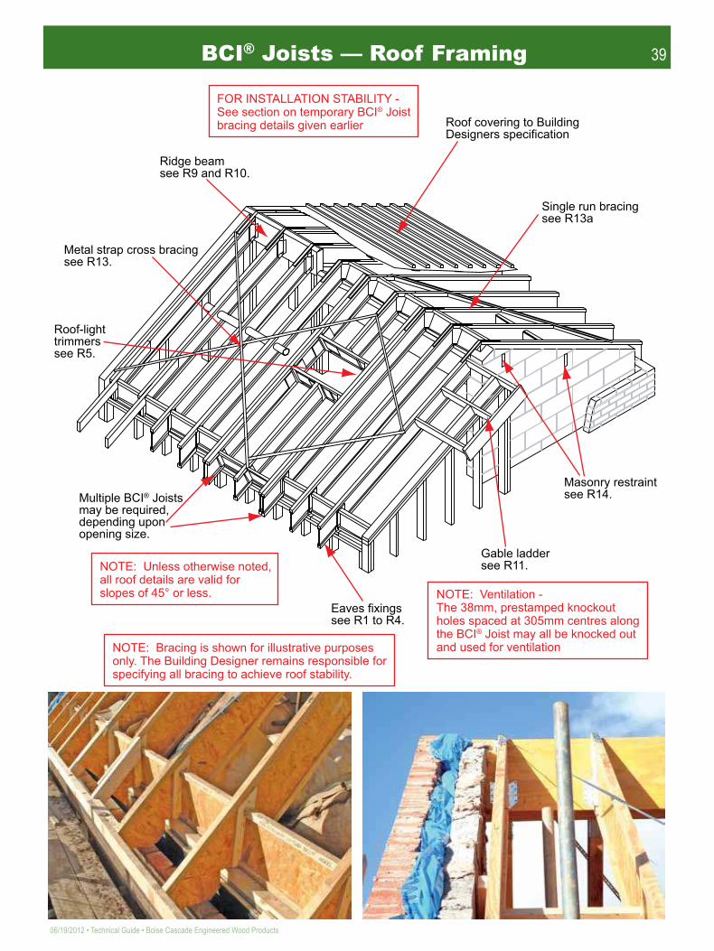
39
06/19/2012 • Technical Guide • Boise Cascade Engineered Wood Products
HQT"KPUVCNNCVKQP"UVCDKNKV["/"Ugg"ugevkqp"qp"vgorqtct{"DEK̶"Lqkuv"dtcekpi"fgvcknu"ikxgp"gctnkgt"
Tkfig"dgco"ugg"T;"cpf"T320"
Tqqh"eqxgtkpi"vq"Dwknfkpi"Fgukipgtu"urgekhkecvkqp"
Ukping"twp"dtcekpi"ugg"T35c"
Ocuqpt{"tguvtckpv"ugg"T360"
Icdng"ncffgt"ugg"T330"
Gcxgu"hkzkpiu"ugg"T3"vq"T60"
Ownvkrng"DEK̶"Lqkuvu"oc{"dg"tgswktgf."fgrgpfkpi"wrqp"qrgpkpi"uk¦g0"
Tqqh/nkijv"vtkoogtu"ugg"T70"
Ogvcn"uvtcr"etquu"dtcekpi"ugg"T350"
PQVG<""Wpnguu"qvjgtykug"pqvgf."cnn"tqqh"fgvcknu"ctg"xcnkf"hqt"unqrgu"qh"67̇"qt"nguu0" PQVG<""Xgpvkncvkqp"/"
Vjg"5:oo."rtguvcorgf"mpqemqwv"jqngu"urcegf"cv"527oo"egpvtgu"cnqpi"vjg"DEK̶"Lqkuv"oc{"cnn"dg"mpqemgf"qwv"cpf"wugf"hqt"xgpvkncvkqp"PQVG<""Dtcekpi"ku"ujqyp"hqt"knnwuvtcvkxg"rwtrqugu"
qpn{0"Vjg"Dwknfkpi"Fgukipgt"tgockpu"tgurqpukdng"hqt"urgekh{kpi"cnn"dtcekpi"vq"cejkgxg"tqqh"uvcdknkv{0"
BCI® Joists — Roof Framing

40
Boise Cascade Engineered Wood Products • Technical Guide • 06/19/2012
BCI® Joists — Roof ApplicationsR1 Bevel plate eave details R1a Bevel plate eaves detail
(timber overhang)
R2 Birdsmouth eaves detail R3 Metal connector eaves detail
R4 Roof eaves & loor junction R5 Roof-light trimming
DEK̶"dnqemkpi"dgvyggp"gcej"tchvgt0
Dgxgnngf"rncvg"hkzgf"vq"ycnn"vq"Dwknfkpi"Fgukipgtu"urgekhkecvkqp0
Hkv"dcemgt"dnqem"dgjkpf"tchvgt"gzvgpukqp"*Hkz"cu"T9c+"
3422oo"jqtk¦0"
972oo"jqtk¦0"
Dnqemkpi"cv"uwrrqtv"pqv"ujqyp"hqt"enctkv{0"
Vkodgt"dnqem0*5:z:;oo"okp0+
5:z:;oo"tchvgt"gzvgpukqp"qpg"ukfg0
5097z97oo"pcknu"cv"372oo"egpvtgu0"
Hncpig"qh"DEK̶"Lqkuvu"oc{"dg"dktfuoqwvj"ewv"qpn{"cv"vjg"nqy"gpf"qh"vjg"lqkuv0"Dktfuoqwvj"ewv"DEK̶"Lqkuv"owuv"dgct"hwnn{"qp"rncvg."tcvjgt"vjcp"qxgtjcpikpi"vjg"kpukfg"hceg"qh"rncvg0"
Ygd"uvkhhgpgt"tgswktgf"cv"gcej"ukfg0"
DEK̶"dnqemkpi0"
DEK̶"dnqemkpi0"
Xctkcdng"rkvej"ogvcn"eqppgevqt"hkzgf"uvtkevn{"kp"ceeqtfcpeg"ykvj"ocpwhcevwtgtu"kpuvtwevkqpu0"
37̇"vq"67̇"
DEK̶"dnqemkpi0"
DEK̶"Lqkuv0"
Vkodgt"dnqemu"cu"tgswktgf"hqt"urgekhke"nqecvkqp0"
DEK̶"Tchvgt"hkzgf"vq"ycnnrncvg"cu"fgvckn"T4"qt"T50" Dcemgt"dnqem0"
Hknngt"dnqem"*ugg"fgvckn"T:+0"
Dcemgt"dnqem"tgswktgf"qp"dqvj"ukfgu"qh"ygd0"Kpuvcnn"vkijv"vq"dqvvqo"hncpig""*ugg"fgvckn"T9c+0"
Hceg"oqwpv"jcpigtu0"

41
06/19/2012 • Technical Guide • Boise Cascade Engineered Wood Products
R6 Web stiffener attachment R7 Backer block application
R7a Backer block (ixing & speciication) R8 Filler block application
R8a Filler block (ixing & speciication) R8b Intermediate iller blocks
Pqvg<""Ygd"uvkhhgpgtu"ctg"pqv"tgswktgf"hqt"DEK̶"Lqkuvu"wpnguu"wugf"kp"jcpigtu"vjcv"fq"pqv"gzvgpf"wr"vq"tguvtckp"vjg"vqr"hncpig"qh"vjg"DEK̶"Lqkuv"qt"cu"tgswktgf"d{"fgukip0
442463524578628
4"/"5057"z"87oo4"/"5057"z"87oo5"/"5057"z"87oo7"/"5057"z"87oo8"/"5057"z"87oo
Lqkuv"Fgrvj Hkzkpiu
Pqvg<"Wug"5097z;2oo"pcknu"hqt";2u"Ugtkgu"Lqkuvu
Vkijv"hkv"vq"dqvvqo
Uocnn"icr<"5oo"okp0."72oo"ocz0
72oo"okp0
72oo"okp0
6722u"Ugtkgu8222u"Ugtkgu82u"Ugtkgu;2u"Ugtkgu
3:z82oo"okp044z82oo"okp047z82oo"okp05:z82oo"okp0
QUD"qt"Rn{yqqf"Ygd"Uvkhhgpgt<
Pqvg<""Hkz"dcemgt"dnqem"wukpi":/Pq"5057z87oo"pcknu"engpejgf"*ugg"fgvckn"T9c+0"Wug"5057z;2oo"pcknu"hqt";2u"Ugtkgu"lqkuv0
Hceg"oqwpv"lqkuv"jcpigt0
Vkijv"hkv0
Dcemgt"dnqem"tgswktgf"qp"dqvj"ukfgu"qh"ygd0
97 97 97522
Ugtkgu"""""""Dcemgt"Dnqem"Vjkempguu"6722u"""3:oo"yqqf"rcpgn"8222u"""47oo"yqqf"rcpgn"82u"""""""47oo"yqqf"rcpgn";2u"""""""3:oo"-"44oo"yqqf"rcpgnu
"Fgrvj Dcemgt"Dnqem"Fgrvju"442oo""""""""""""344oo"463oo""""""""""""369oo"524oo""""""""""""43;oo"578oo""""""""""""48;oo"628oo""""""""""""53;oo
? ?5057z87oo"pcknu"engpejgf*5057z;2oo"pcknu"hqt";2u"Ugtkgu"Lqkuvu+0"
Yjgtg"pcknu"ctg"engpejgf."cnn"pcknu"ecp"dg"ftkxgp"htqo"pgct"ukfg0"
Fgpqvgu"pcknu"htqo"pgct"hceg0Fgpqvgu"pcknu"htqo"hct"hceg0
""
Hkz"4/rn{"DEK̶"Lqkuvu"vqigvjgt"wukpi"hknngt"dnqemu"cv"cnn"dgctkpi"rqkpvu."cv"kpeqokpi"nqcf"rqukvkqpu"cpf"cv"ocz"508o"egpvtgu"*ugg"T:d+0"
Ugg"T:c"hqt"hkzkpi"fgvcknu0"
442oo" 344oo463oo" 369oo524oo" "";9oo"-"344oo578oo" 344oo"-"369oo628oo" 369oo"-"394oo
Lqkuv"Fgrvj Hknngt"Dnqem"Fgrvju
"6722u" 57oo"Vkodgt8222u" 69oo"Vkodgt82u" 69oo"Vkodgt;2u" 97oo"Vkodgt
Hknngt"Dnqem"VjkempguuUgtkgu
Icr"tgswktgf"vq"cxqkf"hqtegf"hkv0
5057z87oo"pcknu"engpejgf*5057z;2oo"pcknu"hqt";2u"Ugtkgu"Lqkuvu+0"
Kpvgtogfkcvg"hknngt"dnqem"kpuvcnngf"yjgp"tgswktgf0"
Hknngt"dnqem"*ugg"T:c"hqt"hkzkpi"fgvckn+0"
508o"oczkowo0
508o"oczkowo0
Pqvg<"Oczkowo"urcekpi"dgvyggp"hknngt"dnqemu"vq"dg"508"ogvtgu0Kpvgtogfkcvg"hknngt"dnqemu"ujqwnf"dg"kpuvcnngf"dgvyggp"dgctkpi"cpf"kpeqokpi"nqcf"rqukvkqpu0
BCI® Joists — Roof Applications

42
Boise Cascade Engineered Wood Products • Technical Guide • 06/19/2012
BCI® Joists — Roof ApplicationsR8c Continuous iller block R9 Downstand ridge beam
R10 Flush ridge beam R11 Gable ladder
R12 Raised ceiling junction (BCI®) R12a Raised ceiling junction (timber)
Pqvg<""C"eqpvkpwqwu"hknngt"cpf"dcemgt"dnqem"ujqwnf"dg"eqpukfgtgf"yjgtg"pwogtqwu"kpeqokpi"lqkuvu"qeewt0"*Ugg"fgvckn"T:c"cpf"T9c"hqt"hkzkpi"fgvcknu0+
Eqpvkpwqwu"dcemgt"dnqem0"
Hknngt"dnqem"
Ukoruqp"NUVC46"qt"ukoknct"uvtcr"cu"tgswktgf"d{"fgukip0"
XGTUC/NCO̶"uwrrqtv"dgco0"
DEK̶"Dnqemkpi"tgswktgf"qp"gcej"ukfg"qh"tkfig0"
Fqwdng/dgxgnngf"vkodgt"rncvg0"
NUVC"qt"ukoknct"uvtcr"cu"tgswktgf"d{"fgukip0"XGTUC/NCO̶"
uwrrqtv"dgco0"
Dgxgnngf"ygd"uvkhhgpgt"gcej"ukfg0"NUUW"jcpigt"
qt"ukoknct0"
N"*822oo"ocz0+"
72oo"qwvtkiigt"ncffgt"pqiikpi"pqvejgf"ctqwpf"DEK̶"vqr"hncpig0"Qwvtkiigt"urcekpi"pq"itgcvgt"vjcp"822oo"egpvtgu0
Fqwdng"lqkuv"oc{"dg"tgswktgf"yjgp"N"gzeggfu"tchvgt"urcekpi0"
Dnqemkpi"cu"tgswktgf0"
Pckn"qwvtkiigt"ncffgt"pqiikpi"vjtqwij"DEK̶"ygd0
Gpf"Ycnn"
Rn{"rcemu"qp"gcej"ukfg"qh"dqvj"tchvgt"cpf"lqkuv0"
DEK̶"Tchvgt0"
4/Pq"34oo"fkc"dqnvu"ykvj"58oo"fkc"z"5oo"vjkem"ycujgtu"qp"dqvj"hcegu0"
DEK̶"Egknkpi"Lqkuv0"
Rn{yqqf"dcemgt"dnqem"hkzgf"vq"gcej"ukfg"qh"tchvgt"vq"gpcdng"hkzkpi"qh"egknkpi"ogodgt"*ugg"fgvckn"T9c+0"
Egknkpi"lqkuv"fgukip"cpf"eqppgevkqp"fgvckn"cu"urgekhkgf"d{"vjg"Dwknfkpi"Fgukipgt0"

43
06/19/2012 • Technical Guide • Boise Cascade Engineered Wood Products
R14 Masonry wall restraint R15 Dormer construction
R16 Flat roof over-hanging eaves R17 Flat roof parapet eaves
R13 Metal strap cross bracing R13a Single run bracingEtquu"dtcekpi"hqtogf"wukpi"302oo"Uvggn"Hkzkpi"Uvtcru"hkzgf"vq"vqr"qh"DEK̶"tchvgtu"wukpi"5097z54oo"uswctg"vykuv"pcknu"*4/Pq"rgt"etquukpi+0"
Pqvg<""Vjg"Dwknfkpi"Fgukipgt"ku"tgurqpukdng"hqt"vjg"cttcpig/ogpv"cpf"swcpvkv{"qh"dtcekpi"vq"rtqxkfg"tqqh"uvcdknkv{0
Tqqh"uvcdknkv{"rtqxkfgf"d{"kpuvcnnkpi"57z94oo"vkodgt"pqiikpiu"dgvyggp"vjg"tchvgtu."ewv"vq"gpuwtg"c"vkijv"hkv0"Ugewtg"vq"tchvgtu"wukpi"3/Pq"5057z87oo"ni"pckn"rgt"gpf0"Eqpvkpwkv{"qh"dtcekpi"rtqxkfgf"d{"kpuvcnnkpi"302oo"OU"Hkzkpi"Uvtkr"qxgt"pqiikpiu."pckngf"eqpvkpwqwun{0"Dtcekpi"vq"dg"kpuvcnngf"cv"crrtqzkocvgn{"67"fgi"vq"tchvgtu"qp"vjg"tqqh"unqrg0
57z94oo"pqiikpi0"
DEK̶"Tchvgt0"
Pqvg<""Vjg"Dwknfkpi"Fgukipgt"ku"tgurqpukdng"hqt"vjg"cttcpigogpv"cpf"swcpvkv{"qh"dtcekpi"vq"rtqxkfg"tqqh"uvcdknkv{0
57z367oo"E38"pqiikpiu"vq"dg"hkzgf"vkijvn{"dgvyggp"DEK̶ "Lqkuvu"cpf"cnuq"dgvyggp"Lqkuv"cpf"ycnn0"
Uvtcr"vq"rcuu"vjtqwij"unqv"ectghwnn{"ewv"kp"DEK̶"Lqkuv"ygd"*Lqkuv"hncpigu"owuv"PQV"dg"ewv+0"
Tguvtckpv"uvtcr"vq"dg"hkzgf"vq"wpewv"dnqem0" Ownvk/rn{"DEK̶"Lqkuvu"
wpfgt"fqtogt"ejggmu0"
Fqtogt"eqpuvtwevkqp"vq"Dwknfkpi"Fgukipgtu"urgekhkecvkqp0"
XGTUC/NCO̶"vtkoogtu0"
Rn{yqqf"ygd"uvkhhgpgt0
Tkodqctf"hkzgf"vq""gcej"lqkuv"wukpi"3/Pq"5057"z"87"ni"icnx"*qt"kortqxgf+"yktg"pckn"vq"gcej"lqkuv"hncpig0"
Cffkvkqpcn"hkzkpi"vq"tkodqctf"cv"ocz"402o"egpvtgu"eqortkukpi"qh"4/Pq"htcokpi"cpejqtu"cpf"rn{yqqf"dcemgtu0
DEK̶ "Dnqemkpi"tgswktgf"kh"ocuqpt{"fqgu"pqv"tguvtckp"DEK̶ "Lqkuv"vqr"hncpig0"
XGTUC/NCO̶""tkodqctf0
Jqnfkpi/fqyp"uvtcr"d{"Dwknfgt"vq"Dwknfkpi"Fgukipgtu"urgekhkecvkqp0
Tqqh"eqxgtkpi"cpf"iwvvgt"fgvcknu"cu"urgekhkgf"d{"vjg"Dwknfkpi"Fgukipgt0
Rctcrgv"ycnn0"
Vjg"Dwknfgt"ku"vq"gpuwtg"vjcv"vjgtg"ku"uwhhkekgpv"ocuqpt{"cdqxg"vjg"jcpigt"vq"oggv"vjg"ocpwhcevwtgtÓu"urgekhkecvkqpu
Tqqh"eqxgtkpi"cpf"iwvvgt"fgvcknu"cu"urgekhkgf"d{"vjg"Dwknfkpi"Fgukipgt0"
Ocuqpt{"jcpigt"kpuvcnngf"kpvq"ycnn"kp"ceeqtfcpeg"ykvj"ocpwhcevwtgtÓu"kpuvtwevkqpu0"
BCI® Joists — Roof Applications

44
Boise Cascade Engineered Wood Products • Technical Guide • 06/19/2012
VERSA-LAM®
VERSA-LAM® products are excel lent as floor and roof framing supports or as lintels for doors, windows and garage doors and columns.
Manufactured with no camber, VERSA-LAM® LVL products provide flatter, quieter floors, and consequently, the builder can expect happier customers with significantly fewer call backs.
VERSA-LAM® is approved for use under the UK Building Regulations by British Board of Agrément BBA Certificate No. 99/3619.BBA certification is recognised by:N.H.B.C. TRA UKTFA Building Control OfficersBuilding Contractors
An Introduction to VERSA-LAM® Products
Materials and Manufacture: VERSA-LAM® LVL comprises laminated Southern Yellow Pine veneers. The veneers are bonded together with waterproof structural adhesives with the grain running parallel. Each veneer is 2550m long, being lap jointed internally and scarf jointed on the face plies. The joints are staggered by at least 125mm.
Quality Assurance: VERSA-LAM® is approved for use in the UK by the British Board of Agrément and is manufactured under a factory production control system audited on a monthly basis by a third-party inspection agency.
Sizes: Whilst VERSA-LAM® can be manufactured and supplied in billets up to 1.2mx1.2mx20m long, it is typically available in thicknesses of 38, 45, 89, 133 and 178mm, and in depths ranging from 89mm to 508mm. Please check for product availability in the UK.
Tolerances: Tolerances in finished dimensions are: Thickness ±1.6mm Width ±3.2mm Length ±3.2mm
Moisture Content: VERSA-LAM® will arrive on-site with a moisture content of 8% to 10%. In a Service Class 1 environment (as defined in BS5268-2:2002), it will attain an equilibrium moisture content of 10%, whilst in a Service Class 2 environment, it will reach a final equilibrium moisture content of 12% to 14%. In similar environments, solid timber will reach an equilibrium moisture content of 12% and 18%, respectively, having typically been delivered to site at approximately 18% to 24% moisture content.
Treatment: VERSA-LAM® is an untreated product with a natural durability sufficient to ensure a minimum design life of 60 years when installed in a Service Class 1 or 2 environment and not subject to mechanical damage or insect attack. Preservative treatment should not be undertaken without consulting Boise Cascade Engineered Wood Products Engineering, as this may affect the structural integrity of the product.
VERSA-LAM® Beam Speciications
442oo463oo524oo578oo628oo
5:oo 67oo :;oo 355oo 39:oo
VERSA-LAM® is one of the strongest and stiffest engineered wood products approved in the UK.

45
06/19/2012 • Technical Guide • Boise Cascade Engineered Wood Products
Figure 1a - Elevation on member - Notches on top edge
Figure 1b - Elevation on member - Holes on centreline
Figure 1c - Elevation on member - Small holes in centreline
VERSA-LAM® is intended for use as structural members such as beams, ties, struts or structural framing (including use in components such as trusses and panels), in Service Class 1 or 2 environments as defined in BS5268-2:2002.
The following design modification factors given in BS5268-2:2002 which can be used for VERSA-LAM® are:
k3, k4, k5, k7, k12, and k13.
The design modification factor k8 for load-sharing may also be used, but with a reduced value of 1.04.
For the design of tension members, design stresses should be modified by a length modification factor kL
as follows:
kL = (2440)0.125
LWhere L = Member length (in mm) with a minimum
value = 2440mm.
VERSA-LAM® Design Properties
Holes and Notches in VERSA-LAM® and VERSA-LAM® RimHoles and notches in VERSA-LAM® and VERSA-LAM® Rim should be formed in accordance with the guidelines given for solid timber members in The Building Regulations Approved Document, “Timber Intermediate Floors for Dwellings,” as shown below. The diagrams below are intended for use with VERSA-LAM® members that support mainly uniform load. Where the load is not uniform or large isolated point loads exist, contact Boise Cascade Engineered Wood Products Engineering for guidance.
Holes/notches that can be formed in VERSA-LAM® without recourse to structural calculationFor members that are predominantly uniformly loaded (i.e. by a series of point loads of essentially equal magnitude and spacing), the holes or notches shown in figures 1a-1c can be formed without recourse to structural calculation.
Property
Value (N/mm2)
Service Class 1
ServiceClass 2
Bending parallel to grain: as a joist . . . . . . . . . . . . . . . . . . . . . . . . . . . . . as a plank . . . . . . . . . . . . . . . . . . . . . . . . . . . .
19.0 19.0
17.1 17.0
Tension parallel to grain . . . . . . . . . . . . . . . . . . 15.0 13.5Compression parallel to grain . . . . . . . . . . . . . . 19.5 17.5Compression perpendicular to grain: as a joist . . . . . . . . . . . . . . . . . . . . . . . . . . . . . as a plank . . . . . . . . . . . . . . . . . . . . . . . . . . . .
4.4 2.9
4.0 2.6
Sheer parallel to grain: as a joist . . . . . . . . . . . . . . . . . . . . . . . . . . . . . as a plank . . . . . . . . . . . . . . . . . . . . . . . . . . . .
2.0 1.3
1.8 1.2
Modulus of elasticity parallel to grain: mean . . . . . . . . . . . . . . . . . . . . . . . . . . . . . . . . minimum . . . . . . . . . . . . . . . . . . . . . . . . . . . . .
14,000 14,000
13,000 13,000
Modulus of elasticity perpendicular to grain 700 650Modulus rigidity . . . . . . . . . . . . . . . . . . . . . . . . . 875 812Density @ 10% mc . . . . . . . . . . . . . . . . . . . . . @ 15% mc . . . . . . . . . . . . . . . . . .
630 kg/m3
690 kg/m3630 kg/m3
690 kg/m3
Ektewnct"jqngu"qh"fkcogvgt"2047J"qt"82oo."yjkejgxgt"ku"nguugt."ctg"rgtokvvgf"kp"vjku"¦qpg"
Urcp."N"
2047N" 2037N"
Hkiwtg"3d"Î"Gngxcvkqp"qp"ogodgt"/"Jqngu"qp"egpvtgnkpg"
FJQNG">"okp"*2047J."82+"
Hkiwtg"3e"Î"Gngxcvkqp"qp"ogodgt"/"Uocnn"jqngu"qp"egpvtgnkpg"
Ektewnct"jqngu"qh"fkcogvgt"wr"vq"203J"qt"52oo."yjkejgxgt"ku"vjg"nguugt."nqecvgf"qp"vjg"ogodgtÓu"jqtk¦qpvcn"egpvtgnkpg."ecp"dg"nqecvgf"cv"cp{"rqkpv"cnqpi"vjg"dgco"gzegrv"ykvjkp"422oo"qh"vjg"dgco"gpfu"
422oo"422oo"
Urcp."N"2029J" 203:J"
Hkiwtg"3c"Î"Gngxcvkqp"qp"ogodgt"/"Pqvejgu"qp"vqr"gfig"
fPQVEJ">"okp"*20347J."52+"
J"
Pqvejgu"qh"fgrvj"qh"20347J"qt"52oo."yjkejgxgt"ku"nguugt."ctg"rgtokvvgf"kp"vjku"¦qpg"Minimum spacing between holes/notches = max(3dNOTCH, 3DHOLE,100mm)
For a design method to calculate large circular holes in VERSA-LAM®, please contact Boise Cascade EWP Engineering on 01420 590078.
VERSA-LAM®

46
Boise Cascade Engineered Wood Products • Technical Guide • 06/19/2012
VERSA-LAM® — Products
Nailed joints in VERSA-LAM® should be designed using the permissible nail values given in BS 5268-2: 2002 for C27 timber. Nails should be spaced in accordance with the following table.
VERSA-LAM® is ideal for use as a principal load-carrying beam in floor, roof and other timber engineering applications. Maximum allowable long-term uniformly distributed loads are tabulated on page 47 for a range of VERSA-LAM® beam sizes over a range of typical beam spans. These have been derived by application of the design principles contained in BS5268-2:2002, using the VERSA-LAM® property data contained in BBA Certificate No. 99/3619. Maximum allowable loads for other beam sizes, spans or load durations can be developed by using the same design principles by using the BC CALC® design software or contacting Boise Cascade Engineering on 01420 590078.
VERSA-LAM® is approved for use under the UK Building Regulations by BBA Certificate No. 99/3619. It is one of the strongest and stiffest engineered wood products currently approved in the UK.BBA Certification is recognized by:
NHBC TRAUKTFA Building Control OfficersBuilding Contractors
VERSA-LAM® Products — Allowable Nail Spacing
VERSA-LAM® Products Used as Beams
Nailing to Narrow Face (Parallel to Glue Lines)Pcknkpi"Rctcnngn"vq"Inwg"nkpgu"*Pcttqy"Hceg+"
Pcknkpi"Rgtrgpfkewnct"vq"Inwg"nkpgu"*Ykfg"Hceg+"
Nail Diameter(mm)
End Distance(mm)
Edge Distance(mm)
Along Face -Parallel to
Grain (mm)
Across Face - Perpendicular to
Grain (mm)
3.0 60 15 60 15
3.35 67 17 67 17
3.75 75 19 75 19
4.0 80 20 80 20
Nailing to Wide Face (Perpendicular to Glue Lines)
Nail Diameter(mm)
End Distance(mm)
Edge Distance(mm)
Along Face -Parallel to
Grain (mm)
Across Face - Perpendicular to
Grain (mm)
3.0 48 15 48 24
3.35 54 17 54 27
3.75 60 19 60 30
4.0 64 20 64 32
CERTIFICATE NO. 99/3619

47
06/19/2012 • Technical Guide • Boise Cascade Engineered Wood Products
Allowable Loads on VERSA-LAM® Beams
BeamSpan /1
(m)
Maximum Allowable Long-Term Uniformly Distributed Load (kN/m) on VERSA-LAM® Beams in Service Class 1 Conditions /2, /3
220mm depth/6 241mm depth/6 302mm depth/6 356mm depth/6 406mm depth/6
45 mm
89 mm
133 mm
178 mm
45 mm
89 mm
133 mm
178 mm
45 mm
89 mm
133 mm
178 mm
45 mm
89 mm
133 mm
178 mm
45 mm
89 mm
133 mm
178 mm
3
3.5
4
4.5
5
5.5
6
6.5
7
7.5
8
8.5
Notes :/1 Beam spans quoted are ‘engineering spans’ measured between
centres of bearing points./2 Maximum loads tabulated are for long-term loading con ditions
including an allowance for the beam self weight. /3 Tabulated loads are based on a deflection limit of 0.3% of the
beam span. The designer should consider the need for improved deflection criteria for principal members, or for aesthetics.
/7 Thicknesses other than those shown may be available by special order.
/4 VERSA-LAM® beams require effective lateral restraint to the compression edge of 600 mm maximum spacing. VERSA-LAM® beams require effective lateral restraint at all supports.
/5 For allowable loads on VERSA-LAM® beams for use in Service Class 2 conditions, contact Boise Cascade Engineered Wood Products Engineering.
/6 The depths shown are for indicative purposes only. Other depths between 89-508mm are available. Consult Boise Cascade Engineered Wood Products Engineering for maximum loads available for other depths.
VERSA-LAM® — Products
4.34 8.69 13.04 17.39 5.66 11.31 17.00 22.69 10.66 21.33 31.99 42.66 15.42 30.85 46.27 61.70 19.86 39.73 59.59 76.46
2.76 5.52 8.28 11.05 3.62 7.24 10.86 14.49 6.89 13.79 20.68 27.58 10.96 21.93 32.90 43.87 14.56 29.12 43.68 58.25
1.85 3.7 5.55 7.41 2.43 4.86 7.29 9.72 4.69 9.38 14.07 18.76 7.52 15.04 22.56 30.09 10.95 21.90 32.85 43.81
1.29 2.58 3.87 5.17 1.70 3.41 5.12 6.83 3.31 6.62 9.93 13.25 5.35 10.70 16.05 21.43 7.85 15.30 23.55 31.41
0.93 1.86 2.79 3.73 1.23 2.47 3.70 4.94 2.42 4.84 7.26 9.68 3.93 7.87 11.79 15.74 5.80 11.60 17.40 23.20
0.68 1.37 2.06 2.75 0.91 1.83 2.73 3.66 1.81 3.62 5.43 7.24 2.96 5.92 8.88 11.85 4.39 8.78 13.17 17.56
0.51 1.03 1.55 2.07 0.69 1.38 2.07 2.77 1.38 2.77 4.15 5.54 2.28 4.56 6.84 9.13 3.39 6.78 10.17 13.56
0.39 0.79 1.18 1.58 0.53 1.06 1.59 2.12 1.07 2.15 3.22 4.30 1.78 3.56 5.34 7.13 2.66 5.33 7.99 10.66
0.30 0.61 0.91 1.22 0.41 0.82 1.23 1.65 0.84 1.69 2.54 3.39 1.41 2.83 4.23 5.66 2.12 4.25 6.37 8.50
0.23 0.47 0.71 0.95 0.32 0.64 0.96 1.29 0.67 1.35 2.02 2.70 1.13 2.27 3.40 4.54 1.71 3.43 5.14 6.86
0.18 0.37 0.55 0.74 0.25 0.51 0.76 1.02 0.54 1.08 1.63 2.17 0.92 1.84 2.77 3.69 1.40 2.80 4.20 5.60
0.14 0.29 0.43 0.58 0.20 0.40 0.60 0.80 0.44 0.88 1.32 1.76 0.75 1.51 2.26 3.02 1.15 2.30 3.45 4.61

48
Boise Cascade Engineered Wood Products • Technical Guide • 06/19/2012
VERSA-LAM® — Products
The same properties that make VERSA-LAM® perfect for beam applications also make them ideal for columns. In VERSA-LAM® columns, you will find none of the deep checks, cracks or twists that can plague solid timber columns.
VERSA-LAM® Column Table
Notes:
• Table assumes that the column is braced at column ends only.
• Effective column length is equal to actual column length.
• Allowable loads are based on solid, one piece column members used in Service Class 1 conditions.
• Allowable loads relate to axially loaded columns only (no bending) and are based on the provisions given in BS5268-2:2002. The modification factor k12 has been calculated using an eccentricity factor of 0.01 of the slenderness ratio, as used in the equation in Annex B of BS5268-2:2002.
Length
(m)
Allowable Axial Load (kN)Long-Term Load Duration
89 x 89 89 x 133 89 x 178 133 x 133 133 x 178 178 x 1781.2 93.681.5 79.95 119.481.8 67.60 101.02 135.202.1 57.00 85.18 114.00 187.962.4 48.19 72.02 96.39 168.39 225.362.7 40.99 61.25 81.98 150.38 201.263.0 35.12 52.49 70.25 134.16 179.553.3 30.34 45.34 60.68 119.75 160.273.6 26.42 39.48 52.84 107.09 143.323.9 23.18 34.64 46.36 96.03 128.524.2 20.48 30.61 40.96 86.39 115.62 228.014.5 18.21 27.22 36.43 77.99 104.38 209.534.8 24.35 32.59 70.67 94.58 192.775.1 29.32 64.26 86.00 177.625.4 58.64 78.48 163.955.7 53.69 71.86 151.626.0 49.32 66.01 140.496.3 45.45 60.83 130.456.6 42.00 56.21 121.366.9 52.09 113.147.2 105.67
VERSA-LAM® Beams Used as Columns
VERSA-LAM® Common Framing Details
Provide lateral restraint at support.
Bearing at masonry walls
Uvtcr"kh"vqr"rncvg"ku"pqv"eqpvkpwqwu"qxgt"jgcfgt0"
Etkrrng"uvwfu0"
Dgctkpi"hqt"fqqt"qt"ykpfqy"nkpvgn"
Xgtkh{"jcpigt"ecrcekv{"ykvj"jcpigt"nkvgtcvwtg"
XGTUC/NCO̶"eqnwop"
Pqvg<"Ftknnkpi"rgtokvvgf"hqt"uvcpfctf"eqppgevqtu0"
FQ"PQV"dgxgn"ewv"XGTUC/NCO̶"dg{qpf"kpukfg"hceg"qh"ycnn"ykvjqwv"crrtqxcn"htqo"Dqkug"Ecuecfg"GYR"Gpikpggtkpi"qt"DE"ECNE̶"uqhvyctg"cpcn{uku0
Jcpigt"
Dgco"vq"ocuqpt{"ycnn"
Vkodgt"vqr"rncvg"owuv"dg"hnwuj"ykvj"kpukfg"qh"ycnn"
Uvtcr"kh"vqr"rncvg"ku"pqv"eqpvkpwqwu"
Dgco"htcokpi"kpvq"ycnn0"
Beam to beam connector
Bearing at column
Rtqxkfg"cfgswcvg""ncvgtcn"uwrrqtv"
Unqrgf"ugcv"ewv0"Pqv"vq"gzeggf""
kpukfg"hceg""qh"dgctkpi0"
VERSA-LAM® Installation Notes• Adequate bearing shall be provided. • VERSA-LAM® beams are intended for use in service class 1 and 2 environments and should be kept
as dry as possible during construction.• Continuous lateral restraint required to compression edge, see note 4 on page 47.

49
06/19/2012 • Technical Guide • Boise Cascade Engineered Wood Products
VERSA-LAM® Nailing Details Simpson Strong-Tie SDS Screw Detail
VERSA-LAM® Ply Thickness
(mm) No. of Plies
Finished Thickness
(mm)
Maximum Long Term Uniform Load (kN/m)
3.35mm x 75mm Nails Simpson Strong-Tie SDS Screw150 c/c 300 c/c 450 c/c 600 c/c 150 c/c 300 c/c 450 c/c 600 c/c
382 76mm 12.32 6.16 4.11 3.08 17.13 8.56 5.71 4.28
3 114mm 4.62 2.31 1.54 1.15 6.42 3.21 2.14 1.60
452 90mm 11.66 5.83 3.88 2.91 17.56 8.78 5.85 4.39
3 135mm 4.37 2.18 1.45 1.09 6.58 3.29 2.19 1.64
Multiple Member Connectors
Notes :1 - The tabulated maximum loads are calculated using the permissible nail and bolt values given in BS 5268-2: 2002 for C27
grade timber, assuming the loading is applied on one side of the beam (via hangers).2 - The tabulated maximum long-term loads for nail fixings can be multiplied by load Duration Factor k48 (1.12 for medium-
term loading and 1.25 for short-term loading).3 - Required washer size for M12 and M16 bolts are minimum 36mm diameter x 3.0mm thick and 48mm diameter x 4.0mm
thick, respectively.4 - The above details are suitable only for VERSA-LAM® depths of 241mm and deeper.5 - Do not use bolts as connections where either the Moment, Bearing or Shear stress values are in excess of 85% of the
permissible values.6 - Refer to Boise Cascade Engineered Wood Products Engineering for fixing details outside those tabulated above.
VERSA- LAM®
Ply Thickness
(mm)
No.of
Plies
Finished Thick-ness (mm)
Maximum Long Term Uniform Load (kN/m)
M12 Bolts M16 Bolts
300c/c
450c/c
600c/c
300c/c
450c/c
600c/c
382 76 25.74 17.16 12.87 31.53 21.02 15.76
3 114 19.31 12.87 9.65 23.64 15.76 11.82
452 90 29.81 19.87 14.90 36.51 24.34 18.25
3 135 22.35 14.90 11.17 27.38 18.25 13.69
892 178 48.63 32.42 24.32 69.82 46.55 34.91
3 267 36.47 24.31 18.23 52.37 34.91 26.18
133 2 266 48.63 32.42 24.31 82.85 55.23 41.42
VERSA-LAM® Bolting Details
XGTUC/NCO"PCKNKPI"FGVCKNU"
Fgpqvgu"pcknu"htqo"pgct"hceg"Fgpqvgu"pcknu"htqo"hct"hceg"*4"Rn{"XGTUC/NCO̶"Pckn"htqo"3"ukfg"qpn{+"
Urcekpi" 97"
5057z97oo"Pcknu"
97"
97"
Ukoruqp"Uvtqpi"/"Vkg"UFU"Uetgy"Fgvckn""
Fgpqvgu"uetgyu"htqo"pgct"hceg"Fgpqvgu"uetgyu"htqo"hct"hceg"*4"Rn{"XGTUC/NCO̶"Uetgy"htqo"3"ukfg"qpn{+"
Urcekpi" 97"
97"
UFU"Uetgyu"
97"
XGTUC/NCO"DQNVKPI"FGVCKNU"
Urcekpi" 97"
O34"qt"O38"Dqnvu"ykvj"ycujgtu"wpfgt""
Dqnv"Jgcfu"cpf"Pwvu"
97"
97"
VERSA-LAM® — Products

50
Boise Cascade Engineered Wood Products • Technical Guide • 06/19/2012
VERSA-LAM® — Products
VERSA-LAM® Beams Used as Rim Material
Maximum Long-Term Load Subject toUniform Compression Perpendicular to Grain
(Service Classes 1 and 2)
ProductMaximum Load Per Metre Run (kN/m)
32mm wide VERSA-STRAND® 49.6
38mm wide VERSA-STRAND® 38mm wide VERSA-LAM® 59.0
45mm wide VERSA-LAM® 69.8
89mm wide VERSA-LAM® 137.8
VERSA-LAM®
The high strength properties enjoyed by VERSA-LAM® make it an ideal rim joist material. This is necessary in timber frame construction to transmit vertical loads across the floor zone between external loadbearing walls.
VERSA-LAM® is produced in 38mm thickness with depths matching the BCI® Joist range.
For higher load transfer applications, 45mm wide or even 89mm wide VERSA-LAM® can be used as a rim.
For lower load transfer applications, 32mm wide or 38mm wide VERSA-STRAND® can provide a very cost-effective alternative.
Maximum long term capacities for each of these products are detailed below:
VERSA-LAM® Products Used as Rim Joists / Bearers
442oo463oo524oo578oo628oo
:;oo

51
06/19/2012 • Technical Guide • Boise Cascade Engineered Wood Products
Concentrated Load Capacities of Boise Cascade Rim ProductsIn platform timber frame construction, point loads (e.g. from heavily loaded studs) are transferred between storeys through the loor zone on their way to the foundation. They are irst imposed on the looring layer, before being transferred through the rim material and then outwards into the timber frame panel below. The concentrated load spreads out as it passes through the rim construction, and then concentrates again as it enters the studs below.
Compression stresses induced at each interface therefore need to be checked against their maximum permissible values in each of the materials, before the limiting concentrated load capacity of the construction can be determined.
The igures on the right illustrate the load distribution path assumed in calculating the stresses induced at each material interface, and the tables below provide the maximum point load that can therefore be sustained at each interface.
It can be seen that in the majority of cases, the point load capacity of rim constructions incorporating Boise Cascade engineered wood products are dictated by the compression capacity of the looring material to withstand such concentrated loads, rather than the rim material itself.
Hnqqtkpi0"
Tko"dqctf0"
Nqcf"fkuvtkdwvkqp"rcvju0"
C denotes maximum capacity of C16 Timber Frame Cripple Stud / Plate.F denotes maximum capacity of 15mm OSB and 18mm or 22mm Chipboard looring.R denotes maximum capacity of Rim Material.Values in bold colour are the limiting capacities.
Flooring Thickness
(mm)
45mm VERSA-LAM®
Cripple Stud Thickness (mm) x 89mm wide
38 2 x 38 3 x 38 4 x 38
C F R C F R C F R C F R
15 7.44 12.96 14.26 14.88 16.38 18.02 22.32 19.80 21.78 29.76 23.22 25.54
18 7.44 13.50 14.85 14.88 16.92 18.61 22.32 20.34 22.37 29.76 23.76 26.14
22 7.44 14.22 15.64 14.88 17.64 19.40 22.32 21.06 23.17 29.76 24.48 26.93
Flooring Thickness
(mm)
32mm VERSA-STRAND®
Cripple Stud Thickness (mm) x 89mm wide
38 2 x 38 3 x 38 4 x 38
C F R C F R C F R C F R
15 7.10 9.21 10.14 14.21 11.65 12.81 21.32 14.08 15.49 28.42 16.51 18.16
18 7.10 9.60 10.56 14.21 12.03 13.24 21.32 14.46 15.91 28.42 16.90 18.59
22 7.35 10.11 11.12 14.71 12.54 13.80 22.07 14.98 16.47 29.43 17.41 19.15
Flooring Thickness
(mm)
38mm VERSA-STRAND® or 38mm VERSA-LAM®
Cripple Stud Thickness (mm) x 89mm wide
38 2 x 38 3 x 38 4 x 38
C F R C F R C F R C F R
15 7.44 10.94 12.04 14.88 13.83 15.22 22.32 16.72 18.39 29.76 19.61 21.57
18 7.44 11.40 12.54 14.88 14.29 15.72 22.32 17.18 18.89 29.76 20.06 22.07
22 7.44 12.01 13.21 14.88 14.90 16.39 22.32 17.78 19.56 29.76 20.67 22.74
BOISE CASCADE RIM PRODUCTS

52
Boise Cascade Engineered Wood Products • Technical Guide • 06/19/2012
Wall Studs
BCI® Joists in Timber Frame Wall Panels
Properties such as strength, stiffness, straightness and light-weight that make BCI® Joists excellent as loor joists also make them ideal for use as studs in timber frame wall panels.
In the wake of Government reports such as Latham’s ‘Constructing the Team’ and Egan’s ‘Rethinking Construction’, developers and designers are increasingly being encouraged to look for more effective methods of building using Modern Methods of Construction (MMC) to reduce build costs, improve construction quality and sustainability and reduce whole life costs whilst anticipating likely future changes in thermal regulations aimed at reducing CO2 emissions.
BCI® Joist wall panels offer an innovative yet simple option to developers as they seek to meet the above aims. Incorporating BCI® Joist studs into a project provides a cost effective way of meeting and exceeding the current thermal insulation requirements whilst eliminating any worries of distortion or shrinkage in the studs. A typical BCI® Joist wall stud panel provides at least 200mm of internal space and when illed with conventional insulation quilt will achieve a U value of about 0.20 W/m2K, yet the wall panel will weigh no more than a conventional solid timber wall panel of 89mm thickness.
The installation of services within a BCI® Joist wall panel is easily achieved by using either the pre-formed knockout holes in the web, or additional holes in the OSB web formed to accommodate larger services. These are far more easily formed than drilling through solid timber studs and BCI® Joists are much more tolerant to the creation of such holes.
Alternatively, an internal service void can be easily incorporated within the BCI® Joist wall panel as shown below right, thereby allowing the easy routing of services and even the opportunity to install services in the factory as part of a pre-completed panel using the latest MMC.
The design and detailing of wall panels incor porating BCI® Joists will be similar to conventional timber frame construction except that the speciic design of the BCI® Joist wall studs will be carried out using a method developed by Boise Cascade. Overall building stability is achieved by means of conventional sheathing material such as OSB or ply.
Ujgcvjkpi0" Dtgcvjgt"ogodtcpg0"
Kpuwncvkqp0"Kpvgtpcn"hkpkuj0"Tgvckpkpi"
dqctf0"
55oo"ugtxkeg"xqkf0"

53
06/19/2012 • Technical Guide • Boise Cascade Engineered Wood Products
Hanger Over-Spread If the hanger is over-spread, it can raise the I-joist above the header and may cause uneven surfaces and squeaky floors.
Hanger Not Plumb A hanger “kicked out” from the header can cause uneven surfaces and squeaky floors.
Toe nailing causes squeaks and improper hanger installations. Do not toe nail I-joists prior to installing either top flange or face mount hangers.
Hanger Over-Spread If the hanger is over-spread, it can raise the I-joist above the header and may cause uneven surfaces and squeaky floors.
Hanger Not Plumb A hanger “kicked out” from the header can cause uneven surfaces and squeaky floors.
Nail at Wrong Angle Nail Too Long
No Web Stiffener Results in Rotation
Hanger side flange is below the joist top flange. No web stiffener results in rotation, unless restrained by other means.
Correct Nailing
No Web Stiffener Installed Hanger side flange supports joist top flange.
Web Stiffener Required Hanger side flange should be at least 60% of joist depth or potential joist rotation must be addressed.
Rotation Resistance If non-skewed hanger side flange is less than 60% of joist depth, attach staggered framing anchors above the hanger.
D
60 % of D
Minimum
D
510mm
Max Less
Than
60% of D
Cullen Building Products Limited
1 Wheatstone Place Southield Industrial Estate Glenrothes Fife KY6 2SW
Tel 01592 771132
Fax 01592 771182
Website www.itw-industry.com/cullen-bp.htm
Simpson Strong-Tie
Winchester Road Cardinal Point Tamworth Staffordshire B78 3HG
Tel 01827 255600
Fax 01827 255616
Website www.strongtie.co.uk
At the heart of the SIMPLE FRAMING SYSTEM® lies Boise Cascade’s innovative range of engineered wood produces. However, other components are often required to construct effective loor and roof framing solutions.
Boise Cascade enjoys excellent technical links with a number of leading manufacturers, conducting ongoing research and development with its supply partners to further the idea of continuous process improvement.
These include the metalwork connector manufacturers Cullen Building Products Limited and Simpson Strong-Tie. Each company produces comprehensive technical data directly relating to our BCI® Joist and VERSA-LAM® products. This data can be obtained via their website addresses or by contacting them directly. Details are below.
BETTER ENGINEERED FOR OVER 30 YEARS
Correct ixing on hangers
Metalwork Connectors

54
Boise Cascade Engineered Wood Products • Technical Guide • 06/19/2012
GlossaryBacker Block . . . . . . . . . OSB or plywood blocks used as a backing plate
where hangers are connected onto an I-Joist at 90o (see detail F11).
BCI® Joist . . . . . . . . . . . An I-Joist product produced exclusively by Boise Cascade using VERSA-LAM® LVL as the flange material and OSB as the web material (see page 6).
Beams . . . . . . . . . . . . . . Structural members which act individually to support applied loads.
Cantilever . . . . . . . . . . . That part of a structural member that extends beyond the supporting superstructure (see page 25-26).
Concentrated Load . . . . Localised load applied at a specific location.
Dead Load . . . . . . . . . . . Permanent loads applied from the materials used in the building.
Deflection . . . . . . . . . . . The deformation of a member due to loads applied to it.
Engineering Span . . . . . Span measured between centres of bearing points – used as the basis for structural calculations on beams/joists (see page 14).
EWP . . . . . . . . . . . . . . . Engineered Wood Products – Reconstituted timber products which use the principle of defect dispersal to improve strength and stability, and reduce the inherent variability of wood.
Filler Block . . . . . . . . . . . OSB, timber or plywood packs fitted between the webs of multi-ply I-Joists to enable them to be rigidly fixed together to form a compound element (see detail F12).
Flange . . . . . . . . . . . . . . Top and bottom parts of an I-Joist which provide the majority of bending resistance when used as a beam.
Floor Performance . . . . The "feel" of a floor which can be affected by many factors (see page 12).
Framing Connectors . . . Metal hangers, clips or straps used to connect structural timber elements together, or to the supporting superstructure (see page 53).
Header. . . . . . . . . . . . . . See Trimmer.
Imposed Load . . . . . . . . Loads arising from the occupancy and use of the building.
Joists . . . . . . . . . . . . . . . Structural members placed at regular centres to support floor loadings.
Knockouts . . . . . . . . . . . 38mm round partially pre-stamped areas within (Knock out holes) the webs of BCI® Joists, which can be used for
the routing of services (see page 28).
Live Load . . . . . . . . . . . . See Imposed Load.
Load Sharing . . . . . . . . . An assembly of at least 4-No structural members spaced at centres no greater than 610mm and tied together by means of decking such that they act together to support a common load.
Long-Term Loading . . . . Loads assumed to act on the structure for a continuous period of 50 years or more (e.g. dead loads plus permanent imposed loads).
LVL . . . . . . . . . . . . . . . . Laminated Veneer Lumber - a reconstituted timber product consisting of thin timber veneers glued together with their grain laying parallel to each other to form a solid beam.
Medium-Term Loading . Loads assumed to act for an accumulated period of no more than 6 months throughout the life of the structure (e.g. snow loadings).
Nogging . . . . . . . . . . . . . Timber battens fixed between joists to provide fixing points for other elements (e.g. plasterboard, restraint straps).
OSB . . . . . . . . . . . . . . . . Orientated Strand Board – a reconstituted timber board material formed by gluing flakes of timber together with their orientation primarily parallel to the board direction.
Perimeter Nogging . . . . Timber battens fixed to the external walls between joist ends to facilitate floor board fixing.
Rafters . . . . . . . . . . . . . . Structural members spaced at regular centres to support roof loadings.
Rim Joist . . . . . . . . . . . . A perimeter beam laid around the external load-bearing walls in timber frame construction to provide lateral stability and act as a closure for the purposes of fire/moisture resistance as well as assisting in transferring vertical loads between upper and lower storey’s (see details F1-F5).
Service Holes . . . . . . . . Site drilled/cut areas through webs of I-Joists which allow free passage of service pipes/conduit (see page 28).
Short-Term Loading . . . . Loads assumed to act for a continuous period of no more than 1-week throughout the life of the structure (e.g. man load).
Squash Blocks . . . . . . . Timber blocks located beneath high concentrated loads, with their end grain vertical, which transfer these loads directly between upper and lower storey’s, thus obviating the need for joists to perform this function (see detail F8a).
Stud Wall Nogging . . . . Timber battens placed between joists beneath non load-bearing walls to provide additional support and facilitate fixing of these walls (see detail F7).
SVP . . . . . . . . . . . . . . . . Soil Vent Pipe.
Temporary Bracing . . . . An arrangement of timber blocking together with diagonal and longitudinal timber members, used to provide temporary lateral restraint to structural floor or roof systems during construction. The principle employed is first to create a laterally "stiff bay" by means of blocking and diagonal members, and then to brace all other joists/rafters back to that "bay" via longitudinal members (see page 27).
Trimmer . . . . . . . . . . . . . Framing member spanning perpendicular to the main floor joists around openings (see page 25).
Trimming Joist . . . . . . . . Joists either side of a structural opening running parallel to the main floor joists, onto which Header Joists are supported (see page 25).
Uniform Loads . . . . . . . . Load applied uniformly over a given length or area.
VERSA-LAM® . . . . . . . . An LVL product produced exclusively by Boise Cascade using Southern Pine (see page 44).
Web . . . . . . . . . . . . . . . . Central portion of an I-Joist providing the majority of shear resistance when used as a beam.
Web Stiffener. . . . . . . . . OSB or plywood blocks fixed to the webs of I-Joists to improve web shear or joist bearing resistance at bearing positions or points of high concentrated load, or used as a web packer to facilitate the fixing of certain types of hangers (see detail F10).
Z-clips . . . . . . . . . . . . . . Folded metal clips fixed to I-Joist flanges to support stud wall noggings (see detail F7).

55
06/19/2012 • Technical Guide • Boise Cascade Engineered Wood Products
Site HandlingSite Storage
Unload from lorry carefully using appropriate equipment.
Do not lift BCI® Joists by top flange.
Avoid lifting BCI® Joists horizontally.Do not drop BCI Joists from height.
Use 150mm min. bearers to keep BCI Joists level and clear of the ground (approx. 3.0m centres).
• Leave BCI® Joists banded together until ready to install.
Warning The following Uses Are Not Allowed
Store BCI® Joists vertically. Do not store flat.
FQ"PQV"ewv"dg{qpf"kpukfg"gfig"qh"dgctkpi0"
FQ"PQV"uwrrqtv"lqkuv"qp"ygd0"
FQ"PQV"ewv"qt"pqvej"hncpig0"
Ugg"tqqh"cpf"hnqqt"fgvcknu"hqt"cnnqygf"ewvvkpi"qh"hncpig0"
FQ"PQV"pckn"enqugt"vjcp"5:oo"htqo"gpf"qh"lqkuv0""""
Wug"5057z87oo"pcknu0"
Tghgt"vq"jqng"nqecvkqp"cpf"uk¦kpi"ejctv"hqt"uk¦g"cpf"urcekpi0"
FQ"PQV"ycnm"qp"lqkuv"wpvkn"rtqrgt"dtcekpi"ku"kp"rnceg0""FQ"PQV"nqcf"lqkuv"dg{qpf""fgukip"ecrcekv{0""FQ"PQV"uvcem""dwknfkpi"ocvgtkcnu"qp""wpdtcegf"lqkuvu0"
FQ"PQV"kpuvcnn"vqpiwg"qh"hnqqt"ujgcvjkpi"hnwuj"ykvj"XGTUC/NCO̶"0"Vtko"vqpiwg"hnwuj"ykvj"tko0
"
XGTUC/NCO̶"
V(I"Hnqqt"Ujgcvjkpi"
FQ"PQV"jcoogt"qp"ygd"wpnguu"tgoqxkpi"mpqemqwv"jqngu0"
FQ"PQV"jcoogt"qp"hncpig0"
FQ"PQV"ewv"jqngu"vqq"enqug"vq"uwrrqtvu"qt"vq"gcej"qvjgt0""
FQ"PQV"ewv"pqvejgu"qt"jqngu"vjcv"ctg"pqv"kp"ceeqtfcpeg"ykvj"vjku"Vgejpkecn"Iwkfg0"
Vtko"vqpiwg"qh"ujgcvjkpi"tgictfnguu"qh"tkodqctf"vjkempguu0"
• Protect BCI® Joists from the weather.
Contractors should be aware of their health and
safety responsibilities under the Construction
(Design & Management) Regulations 1994
Helpful Hints

Left Page56
Boise Cascade Engineered Wood Products3 The Long Barn Brynkinalt Business Centre Chirk Wrexham LL14 5NS
T 01691 770530 F 01691 770535
[email protected] - Email
www.BC.com/eu - Website
For speciic engineering advice, please contact Boise Cascade EWP Engineering on 01420 590078
Boise Cascade Engineered Wood Products • Technical Guide • 06/19/2012
Available from