Failure Modes and EffectFAILURE MODES AND EFFECTS ANALYSIS (FMEA)Analysis (Fmea)
A Systems Approach to Failure Modes, Mechanisms, Effects and Causes
1
A Systems Approach to Failure Modes, Mechanisms, Effects and Causes Technical Paper 0003/sb January 2018
Dr Stuart Burge Abstract Failure Mode and Effect Analysis (FMEA) is ubiquitous throughout industry and commerce, yet its deployment is often fraught with difficulty and its application ephemeral. It is argued in this paper that root cause of these difficulties is an incomplete and inconsistent understanding of failure. This paper uses concepts and principles from Systems Thinking to provide a clear, repeatable and reproducible approach to failure and its associated aspects that greatly facilitate the deployment and application of FMEA in all its forms. It also argues for the need to adopt an even earlier form of FMEA as a precursor to a Design FMEA and Process FMEA. The intent of what is called Functional FMEA is to identify issues before design commences such that they can be designed out ab initio.
Copyright and IPR Notice: Copyright and IPR exists and is held by BHW and the Systems Engineering Company. This work must not be copied,
distributed or otherwise used without the express permission of BHW
A Systems Approach to Failure Modes, Mechanisms, Effects and Causes
2
1.0 Introduction The use of Failure Mode and Effect Analysis (FMEA), in all its incarnations, is ubiquitous throughout industry and commerce, yet its deployment is often fraught with difficulty and its application ephemeral. What appears, prima facie, to be a simple tool turns out to be used inconsistently with a corresponding high degree of frustration and lack of confidence. Part of the problem lies with the published works on this fundamentally simple tool. Indeed, even the recognized writers in the field demonstrate a distinct degree of inconsistency. This paper uses concepts from Systems Thinking to provide a clear, repeatable and reproducible approach to FMEA whether it is Design or Process. It also argues for the need to adopt an even earlier form of FMEA as a precursor to a Design FMEA and Process FMEA. The intent of what is called Functional FMEA is to identify issues before design commences such that they can be designed out ab initio. The paper is split into 4 sections. The first provides an overview of the generic “text book” FMEA process. The second describes some of the common issues that are encountered with its application, while the third presents the systems approach that focuses on the need for a clear understanding of function. It is argued that a clear understanding of the function(s) of a design or process provides a simple and elegant method of deriving the failure modes and hence the causal chain that defines the failure mechanism. The last section introduces the Functional FMEA as a tool that can be applied at the requirements stage, before design has begun, in order to identify issues early and design them out. 2.0 “Text Book” FMEA 2.1 History The purpose of this section is to describe what is currently written about FMEA in the published literature. It is not a literature review, but more a condensation of what is written about the tool. There are numerous accounts of FMEA that vary in depth and understanding. This section draws upon a number of published works [1 to 7] to attempt to provide a common overview of the tool, its purpose and process. The history of FMEA is certainly not clear. What is certain is that the major impetus for its use originates with the US Military. Indeed, the origins of FMEA can be traced back to the US military standard MIL-P-1629 (1949) which describes the process for conducting a “Failure Modes, Effects and Criticality Analysis” (FMECA). It is indeed a misconception that FMEA and FMECA are different. Originally, they were; FMEA did what its name suggests: it identified and documented the failure modes and effects. The inclusion of numerical assessments of severity of effect, probability of occurrence and ability to
A Systems Approach to Failure Modes, Mechanisms, Effects and Causes
3
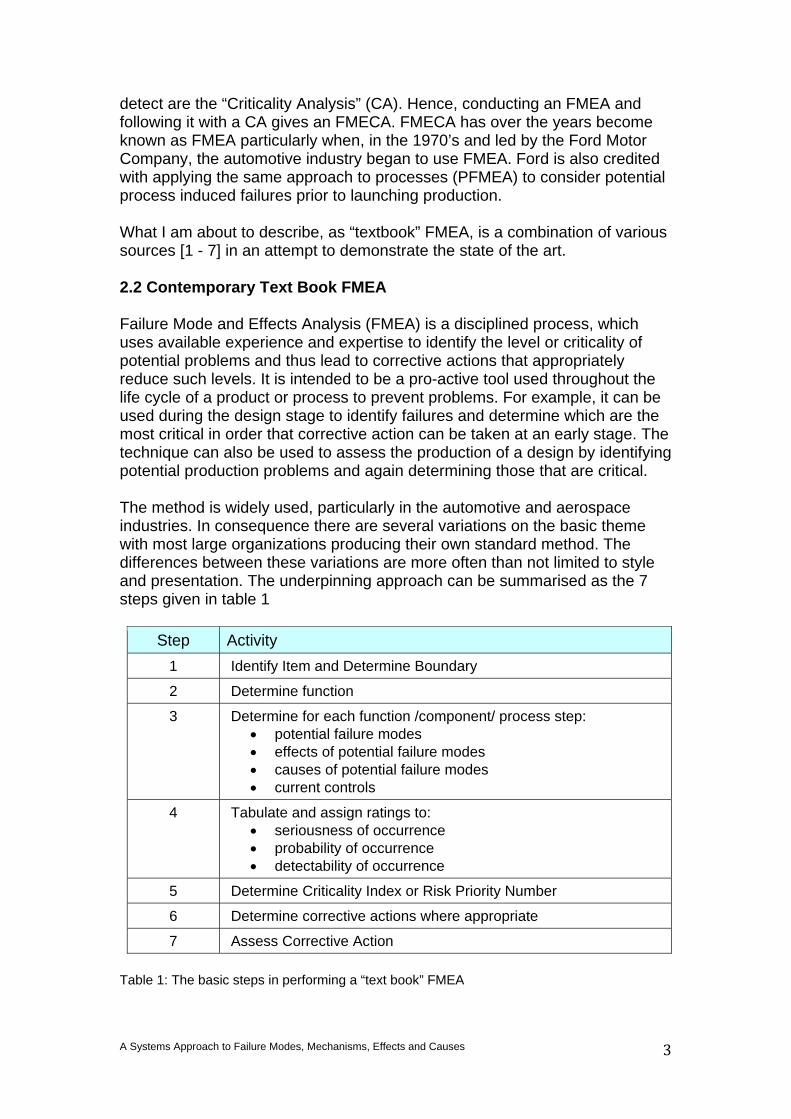
detect are the “Criticality Analysis” (CA). Hence, conducting an FMEA and following it with a CA gives an FMECA. FMECA has over the years become known as FMEA particularly when, in the 1970’s and led by the Ford Motor Company, the automotive industry began to use FMEA. Ford is also credited with applying the same approach to processes (PFMEA) to consider potential process induced failures prior to launching production. What I am about to describe, as “textbook” FMEA, is a combination of various sources [1 - 7] in an attempt to demonstrate the state of the art. 2.2 Contemporary Text Book FMEA Failure Mode and Effects Analysis (FMEA) is a disciplined process, which uses available experience and expertise to identify the level or criticality of potential problems and thus lead to corrective actions that appropriately reduce such levels. It is intended to be a pro-active tool used throughout the life cycle of a product or process to prevent problems. For example, it can be used during the design stage to identify failures and determine which are the most critical in order that corrective action can be taken at an early stage. The technique can also be used to assess the production of a design by identifying potential production problems and again determining those that are critical. The method is widely used, particularly in the automotive and aerospace industries. In consequence there are several variations on the basic theme with most large organizations producing their own standard method. The differences between these variations are more often than not limited to style and presentation. The underpinning approach can be summarised as the 7 steps given in table 1
Step Activity 1 Identify Item and Determine Boundary
2 Determine function
3 Determine for each function /component/ process step: • potential failure modes • effects of potential failure modes • causes of potential failure modes • current controls
4 Tabulate and assign ratings to: • seriousness of occurrence • probability of occurrence • detectability of occurrence
5 Determine Criticality Index or Risk Priority Number
6 Determine corrective actions where appropriate
7 Assess Corrective Action Table 1: The basic steps in performing a “text book” FMEA
A Systems Approach to Failure Modes, Mechanisms, Effects and Causes
4
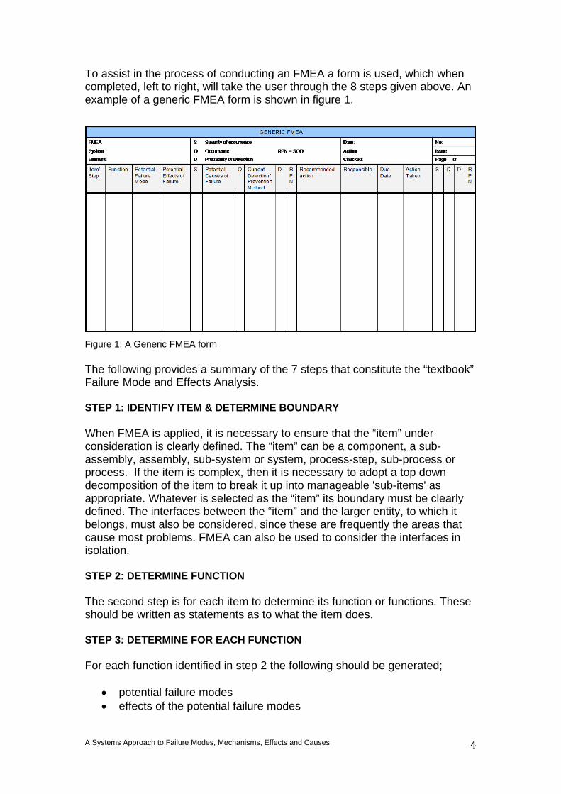
To assist in the process of conducting an FMEA a form is used, which when completed, left to right, will take the user through the 8 steps given above. An example of a generic FMEA form is shown in figure 1.
Figure 1: A Generic FMEA form The following provides a summary of the 7 steps that constitute the “textbook” Failure Mode and Effects Analysis. STEP 1: IDENTIFY ITEM & DETERMINE BOUNDARY When FMEA is applied, it is necessary to ensure that the “item” under consideration is clearly defined. The “item” can be a component, a sub-assembly, assembly, sub-system or system, process-step, sub-process or process. If the item is complex, then it is necessary to adopt a top down decomposition of the item to break it up into manageable 'sub-items' as appropriate. Whatever is selected as the “item” its boundary must be clearly defined. The interfaces between the “item” and the larger entity, to which it belongs, must also be considered, since these are frequently the areas that cause most problems. FMEA can also be used to consider the interfaces in isolation. STEP 2: DETERMINE FUNCTION The second step is for each item to determine its function or functions. These should be written as statements as to what the item does. STEP 3: DETERMINE FOR EACH FUNCTION For each function identified in step 2 the following should be generated;
• potential failure modes • effects of the potential failure modes
A Systems Approach to Failure Modes, Mechanisms, Effects and Causes
5
• cause(s) of the potential failure modes • current controls
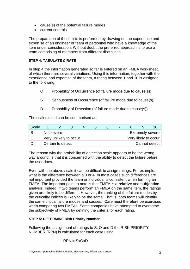
The preparation of these lists is performed by drawing on the experience and expertise of an engineer or team of personnel who have a knowledge of the item under consideration. Without doubt the preferred approach is to use a team comprising of members from different disciplines. STEP 4: TABULATE & RATE In step 4 the information generated so far is entered on an FMEA worksheet, of which there are several variations. Using this information, together with the experience and expertise of the team, a rating between 1 and 10 is assigned to the following; O Probability of Occurrence (of failure mode due to cause(s)) S Seriousness of Occurrence (of failure mode due to cause(s)) D Probability of Detection (of failure mode due to cause(s)) The scales used can be summarised as; Scale 1 2 3 4 5 6 7 8 9 10 S Not severe Extremely severe O Very unlikely to occur Very likely to occur D Certain to detect Cannot detect
The reason why the probability of detection scale appears to be the wrong way around, is that it is concerned with the ability to detect the failure before the user does. Even with the above scale it can be difficult to assign ratings. For example, what is the difference between a 3 or 4. In most cases such differences are not important provided the team or individual is consistent when forming an FMEA. The important point to note is that FMEA is a relative and subjective analysis. Indeed, if two teams perform an FMEA on the same item, the ratings given are likely to be different. However, the ranking of the failure modes by the criticality indices is likely to be the same. That is, both teams will identify the same critical failure modes and causes. Care must therefore be exercised when comparing two FMEAs. Some companies have attempted to overcome the subjectivity of FMEA by defining the criteria for each rating. STEP 5: DETERMINE Risk Priority Number Following the assignment of ratings to S, O and D the RISK PRIORITY NUMBER (RPN) is calculated for each case using RPN = SxOxD
A Systems Approach to Failure Modes, Mechanisms, Effects and Causes
6
The larger this number, the more serious or more critical the failure mode. An important point to note is that criticality of a failure is not just dependent on its likelihood of occurrence. Indeed, emphasis is placed on how the user is “affected” if the failure, however remote, were to occur. Once all the criticality indices have been calculated, a summary of the most critical is extracted in order to highlight those areas where priority action must be directed. It is also recognised practice to highlight any failures that contain a 10 for Severity, Occurrence or Detection irrespective of the other ratings STEP 6: CORRECTIVE ACTION Having identified the critical failure modes, appropriate remedial action it is considered. This should result in a series of corrective actions, which are stated clearly on the FMEA form and “actioned” to be carried out. An important feature of the FMEA, because it does not just concentrate on probability of occurrence, is that the ratings can give direction as to the appropriate corrective action. STEP 7: ASSESS CORRECTIVE ACTION The last step is common sense. The purpose of FMEA is not only to identify potential problems but also to provide corrective action. Step 7 is therefore a repeat of the FMEA to ensure that the corrective actions do actually reduce the criticality index. 3.0 Failings of Textbook FMEA Despite its apparent simplicity the application of FMEA in commerce and industry is often fraught with difficulty. Indeed, many organizations take several years to successfully deploy and embed FMEA. The argument put forward in this paper is that FMEA is difficult to implement because of a lack of understanding of failure. The word “failure” is so frequently used in everyday conversations that we all feel we have an inherent, and complete understanding of its meaning. Furthermore, we are also familiar with the concept of cause and effect; every failure must have some root cause. It can be argued that this recognition of cause and effect is not a bad thing, but it is often perceived in simple linear terms. We naturally assume that an effect has a single cause. It is one “thing” that has caused the end event. People like to find a single item of blame. Reality suggests, however, that multiple and complex cause and effect chains are the norm. This over familiarity with “failure” and linear “cause and effect” results in a lack of rigour and discipline because we all believe we know what we are doing. The other major contributing factor to the failings of FMEA is failure itself. Nobody plans to fail, but failures do occur. In fact, they occur on a daily basis with a consequential impact on cost, time and also reputation. It therefore
A Systems Approach to Failure Modes, Mechanisms, Effects and Causes
7
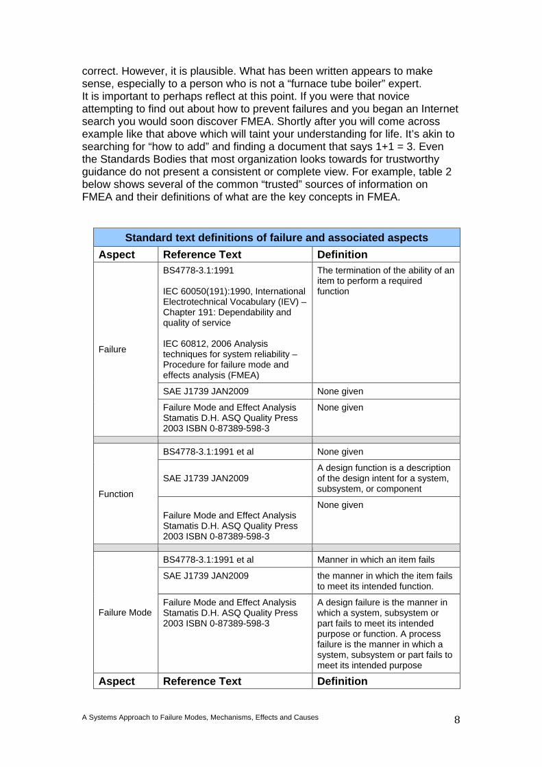
follows when failures do occur we address them with a sense of urgency, we wish to impress upon those affected by the failure that we are doing everything in our power to put it right. We divert resources to fix the failure, we put our senior people “on the job” because are keen to be seen to be “doing something”. The ubiquitous nature of FMEA is a reflection of the ubiquitous nature of failure and the need to do something now! Even the less astute of organizations will soon realise that “fixing failures” is wasteful and recognise the need to attempt to prevent failure and begin a quest for the “holy grail”. That search is often short and sweet because FMEA appears through the mist as a knight in shining armour. It is appealing on many levels. It is a simple tool and most people with their inherent understand of failure and cause and effect feel they can quickly grasp the process and intent. It has numbers and therefore has a “scientific” quantitative feel but is not mathematical. Other potentially useful tools such as Reliability Block Diagrams, Design of Experiments, Sensitivity Analysis, Monte Carlo Analysis, Fault Tree Analysis etc. are overlooked because the maths involved appears too hard! There is also plenty of literature on FMEA. Many people have trod this path leading to the over documentation and an “over-availability” of literature on FMEA, particularly on the Internet! This glut of FMEA literature should be useful. It is not. Everybody has their take on FMEA that stems from their understanding of failure. In consequence FMEA is reported in an inconsistent and incomplete fashion. To all intents and purposes, FMEA is a simple tool and therefore most people feel they are able to understand its application. Moreover, they can complete the FMEA form and it “looks good” – it “looks right”. Unfortunately, the fact you can put something in a column of an FMEA form does not mean it is correct. To illustrate this, below is an example obtained from the Internet on 7 January 2014. It was obtained using a Safari browser and used the search word “Failure Mode”. One of the items in the top 10 was entitled “The difference between root cause and failure mode” – potentially an interesting online debate – but it included the following example cited as helping in the debate:
Box 1: An Internet example to help explain cause and failure mode (incorrectly) At first glance this looks like a reasonable example – but it is wrong! Aspects are correct. The author got the “Equipment” aspect right, but the rest is not
EQUIPMENT: e.g. furnace tube boiler
FAILURE: (what happened) e.g. Catastrophic failure of the welded joint between the furnace tube and tube plate.
FAILURE MODE: (by definition is what the equipment or component failed from) e.g. Corrosion fatigue.
ROOT CAUSE/S: (by definition, what caused the failure mode to occur AND what can be changed to prevent re-occurrence. Remember there can be more than one!!)e.g. Poor feed water treatment accelerated corrosion; Rapid firing, particularly from cold, increased thermal stress on the boiler; Over pressurization and temperature cycles.
A Systems Approach to Failure Modes, Mechanisms, Effects and Causes
8
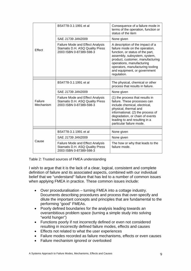
correct. However, it is plausible. What has been written appears to make sense, especially to a person who is not a “furnace tube boiler” expert. It is important to perhaps reflect at this point. If you were that novice attempting to find out about how to prevent failures and you began an Internet search you would soon discover FMEA. Shortly after you will come across example like that above which will taint your understanding for life. It’s akin to searching for “how to add” and finding a document that says 1+1 = 3. Even the Standards Bodies that most organization looks towards for trustworthy guidance do not present a consistent or complete view. For example, table 2 below shows several of the common “trusted” sources of information on FMEA and their definitions of what are the key concepts in FMEA.
Standard text definitions of failure and associated aspects Aspect Reference Text Definition
Failure
BS4778-3.1:1991 IEC 60050(191):1990, International Electrotechnical Vocabulary (IEV) – Chapter 191: Dependability and quality of service IEC 60812, 2006 Analysis techniques for system reliability – Procedure for failure mode and effects analysis (FMEA)
The termination of the ability of an item to perform a required function
SAE J1739 JAN2009 None given
Failure Mode and Effect Analysis Stamatis D.H. ASQ Quality Press 2003 ISBN 0-87389-598-3
None given
Function
BS4778-3.1:1991 et al None given
SAE J1739 JAN2009
A design function is a description of the design intent for a system, subsystem, or component
Failure Mode and Effect Analysis Stamatis D.H. ASQ Quality Press 2003 ISBN 0-87389-598-3
None given
Failure Mode
BS4778-3.1:1991 et al Manner in which an item fails
SAE J1739 JAN2009 the manner in which the item fails to meet its intended function.
Failure Mode and Effect Analysis Stamatis D.H. ASQ Quality Press 2003 ISBN 0-87389-598-3
A design failure is the manner in which a system, subsystem or part fails to meet its intended purpose or function. A process failure is the manner in which a system, subsystem or part fails to meet its intended purpose
Aspect Reference Text Definition
A Systems Approach to Failure Modes, Mechanisms, Effects and Causes
9
Effect
BS4778-3.1:1991 et al Consequence of a failure mode in terms of the operation, function or status of the item
SAE J1739 JAN2009 None given
Failure Mode and Effect Analysis Stamatis D.H. ASQ Quality Press 2003 ISBN 0-87389-598-3
A description of the impact of a failure mode on the operation, function, or status of the part, assembly, subsystem, system, product, customer, manufacturing operations, manufacturing operators, manufacturing tooling and equipment, or government regulation.
Failure Mechanism
BS4778-3.1:1991 et al The physical, chemical or other process that results in failure.
SAE J1739 JAN2009 None given
Failure Mode and Effect Analysis Stamatis D.H. ASQ Quality Press 2003 ISBN 0-87389-598-3
(1) the process that results in failure. These processes can include chemical, electrical, physical, thermal and informational. (2) the process of degradation, or chain of events leading to and resulting in a particular failure mode.
Cause
BS4778-3.1:1991 et al None given
SAE J1739 JAN2009 None given
Failure Mode and Effect Analysis Stamatis D.H. ASQ Quality Press 2003 ISBN 0-87389-598-3
The how or why that leads to the failure mode.
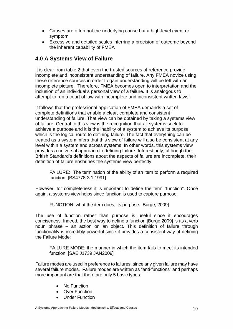
Table 2: Trusted sources of FMEA understanding I wish to argue that it is the lack of a clear, logical, consistent and complete definition of failure and its associated aspects, combined with our individual belief that we “understand” failure that has led to a number of common issues when applying FMEA in practice. These common issues include:
• Over proceduralisation – turning FMEA into a cottage industry. Documents describing procedures and process that over-specify and dilute the important concepts and principles that are fundamental to the performing “good” FMEAs.
• Poorly defined boundaries for the analysis leading towards an overambitious problem space (turning a simple study into solving “world hunger”)
• Functions poorly if not incorrectly defined or even not considered resulting in incorrectly defined failure modes, effects and causes
• Effects not related to what the user experiences • Failure modes recorded as failure mechanisms, effects or even causes • Failure mechanism ignored or overlooked
A Systems Approach to Failure Modes, Mechanisms, Effects and Causes
10
• Causes are often not the underlying cause but a high-level event or symptom
• Excessive and detailed scales inferring a precision of outcome beyond the inherent capability of FMEA
4.0 A Systems View of Failure It is clear from table 2 that even the trusted sources of reference provide incomplete and inconsistent understanding of failure. Any FMEA novice using these reference sources in order to gain understanding will be left with an incomplete picture. Therefore, FMEA becomes open to interpretation and the inclusion of an individual’s personal view of a failure. It is analogous to attempt to run a court of law with incomplete and inconsistent written laws! It follows that the professional application of FMEA demands a set of complete definitions that enable a clear, complete and consistent understanding of failure. That view can be obtained by taking a systems view of failure. Central to this view is the recognition that all systems seek to achieve a purpose and it is the inability of a system to achieve its purpose which is the logical route to defining failure. The fact that everything can be treated as a system infers that this view of failure will also be consistent at any level within a system and across systems. In other words, this systems view provides a universal approach to defining failure. Interestingly, although the British Standard’s definitions about the aspects of failure are incomplete, their definition of failure enshrines the systems view perfectly:
FAILURE: The termination of the ability of an item to perform a required function. [BS4778-3.1:1991]
However, for completeness it is important to define the term “function”. Once again, a systems view helps since function is used to capture purpose:
FUNCTION: what the item does, its purpose. [Burge, 2009] The use of function rather than purpose is useful since it encourages conciseness. Indeed, the best way to define a function [Burge 2009] is as a verb noun phrase – an action on an object. This definition of failure through functionality is incredibly powerful since it provides a consistent way of defining the Failure Mode:
FAILURE MODE: the manner in which the item fails to meet its intended function. [SAE J1739 JAN2009]
Failure modes are used in preference to failures, since any given failure may have several failure modes. Failure modes are written as “anti-functions” and perhaps more important are that there are only 5 basic types:
• No Function • Over Function • Under Function
A Systems Approach to Failure Modes, Mechanisms, Effects and Causes
11
• Intermittent Function • Unintended Function
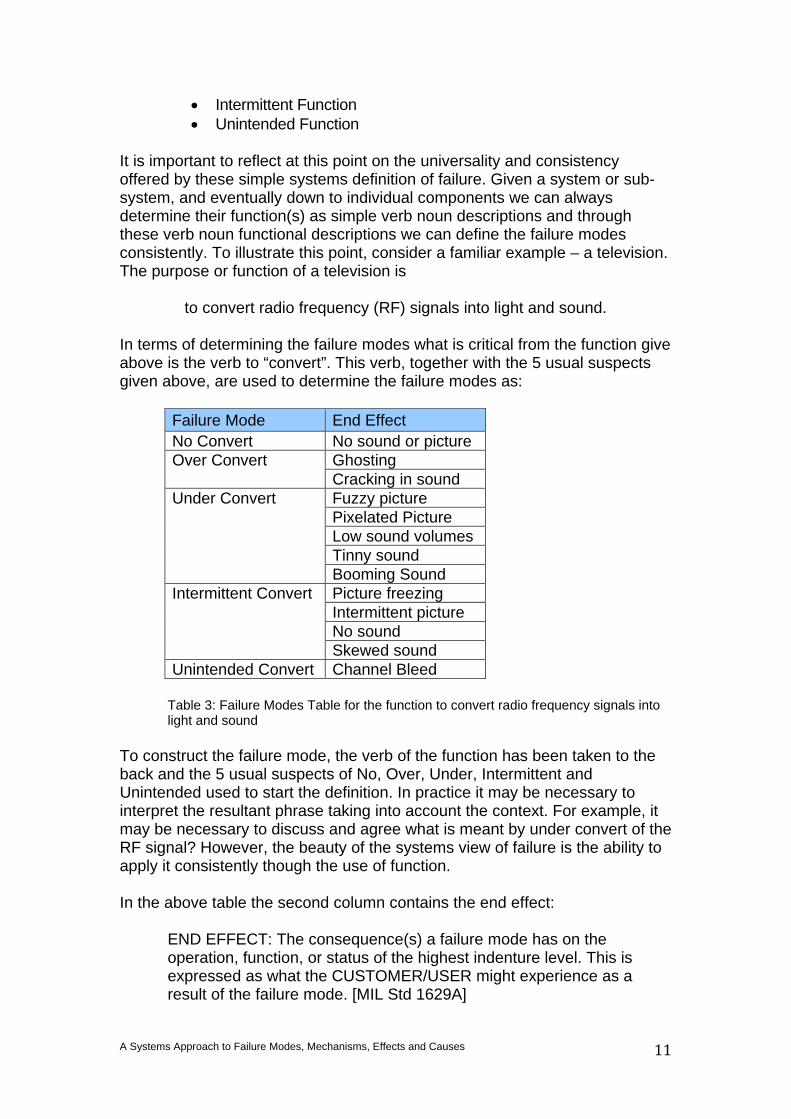
It is important to reflect at this point on the universality and consistency offered by these simple systems definition of failure. Given a system or sub-system, and eventually down to individual components we can always determine their function(s) as simple verb noun descriptions and through these verb noun functional descriptions we can define the failure modes consistently. To illustrate this point, consider a familiar example – a television. The purpose or function of a television is
to convert radio frequency (RF) signals into light and sound. In terms of determining the failure modes what is critical from the function give above is the verb to “convert”. This verb, together with the 5 usual suspects given above, are used to determine the failure modes as:
Failure Mode End Effect No Convert No sound or picture Over Convert Ghosting
Cracking in sound Under Convert Fuzzy picture
Pixelated Picture Low sound volumes Tinny sound Booming Sound
Intermittent Convert Picture freezing Intermittent picture No sound Skewed sound
Unintended Convert Channel Bleed
Table 3: Failure Modes Table for the function to convert radio frequency signals into light and sound
To construct the failure mode, the verb of the function has been taken to the back and the 5 usual suspects of No, Over, Under, Intermittent and Unintended used to start the definition. In practice it may be necessary to interpret the resultant phrase taking into account the context. For example, it may be necessary to discuss and agree what is meant by under convert of the RF signal? However, the beauty of the systems view of failure is the ability to apply it consistently though the use of function. In the above table the second column contains the end effect:
END EFFECT: The consequence(s) a failure mode has on the operation, function, or status of the highest indenture level. This is expressed as what the CUSTOMER/USER might experience as a result of the failure mode. [MIL Std 1629A]
A Systems Approach to Failure Modes, Mechanisms, Effects and Causes
12
It is clear from table 3 that a particular failure mode can have several end effects. In this particular instance, this is partially due to a television having two prime functions: the conversion of RF signals to light and the conversion of RF signals to sound. Table 3 also shows what is called the “End” effect – what the user of the system will actually experience. Dependent upon the “item” under investigation there are other possible effects. In some systems it may be necessary to think of the effect scenario through the levels of a system. This leads to a number of additional effects at different levels:
LOCAL EFFECT: The consequence(s) a failure mode has on the operation, function, or status of the specific item being analysed. [MIL Std 1629A] NEXT HIGHER-LEVEL EFFECT: The consequence(s) a failure mode has on the operation, functions, or status of the items in the next higher indenture level above the indenture level under consideration. [MIL Std 1629A]
There are however, other aspects to failure that are important. Firstly, there is always something that causes the failure mode to occur.
CAUSE: the underlying event that leads to a failure mode. However, there is one final aspect of failure that is often overlooked and ignored. This is the failure mechanism that is the “road between the cause and effect”:
FAILURE MECHANISM: The physical, chemical or other process that results in failure. [BS4778-3.1:1991]
The “Failure Mechanism” is interesting because most FMEA forms do not have a column for it and in consequence people often confuse failure mode1 and failure mechanism. It is not uncommon to find “fatigue” or “corrosion” given as a Failure Mode. It is also possible to find these words appearing in the causes column! Both are incorrect, “fatigue” and “corrosion” are Failure Mechanisms – they are the chemical or physical process that results in failure. Something will cause the item to fatigue or corrode – it is this that should be recorded in the Cause column. The Failure Mode will be how an item fails to meet its intended function as a consequence of fatigue or corrosion. It is perhaps easy now to see why it was possible to declare the example given in box 1 as incorrect. Typically, Failure Mechanisms comprise physical degradation of the item and its components due to local operational conditions in combination with aspects such as design features, materials and surface treatments.
1 In the case of “failure mode” BS 4778 actually doesn’t help! BS 4778 defines a failure mode as: “The effect by which a failure is observed”. The lack of reference to the “function” presents an inconsistency within the BSI approach.
A Systems Approach to Failure Modes, Mechanisms, Effects and Causes
13
Different engineering disciplines will attract typical Failure Mechanisms. For example, in mechanical design, Failure Mechanisms can involve for example:
Corrosion Embrittlement Fatigue
Fretting Wear
Work hardening Electronic design
Dielectric breakdown Electromigration Induced current
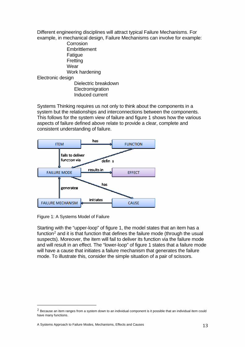
Systems Thinking requires us not only to think about the components in a system but the relationships and interconnections between the components. This follows for the system view of failure and figure 1 shows how the various aspects of failure defined above relate to provide a clear, complete and consistent understanding of failure.
Figure 1: A Systems Model of Failure Starting with the “upper-loop” of figure 1, the model states that an item has a function2 and it is that function that defines the failure mode (through the usual suspects). Moreover, the item will fail to deliver its function via the failure mode and will result in an effect. The “lower-loop” of figure 1 states that a failure mode will have a cause that initiates a failure mechanism that generates the failure mode. To illustrate this, consider the simple situation of a pair of scissors.
2 Because an item ranges from a system down to an individual component is it possible that an individual item could have many functions.
A Systems Approach to Failure Modes, Mechanisms, Effects and Causes
14
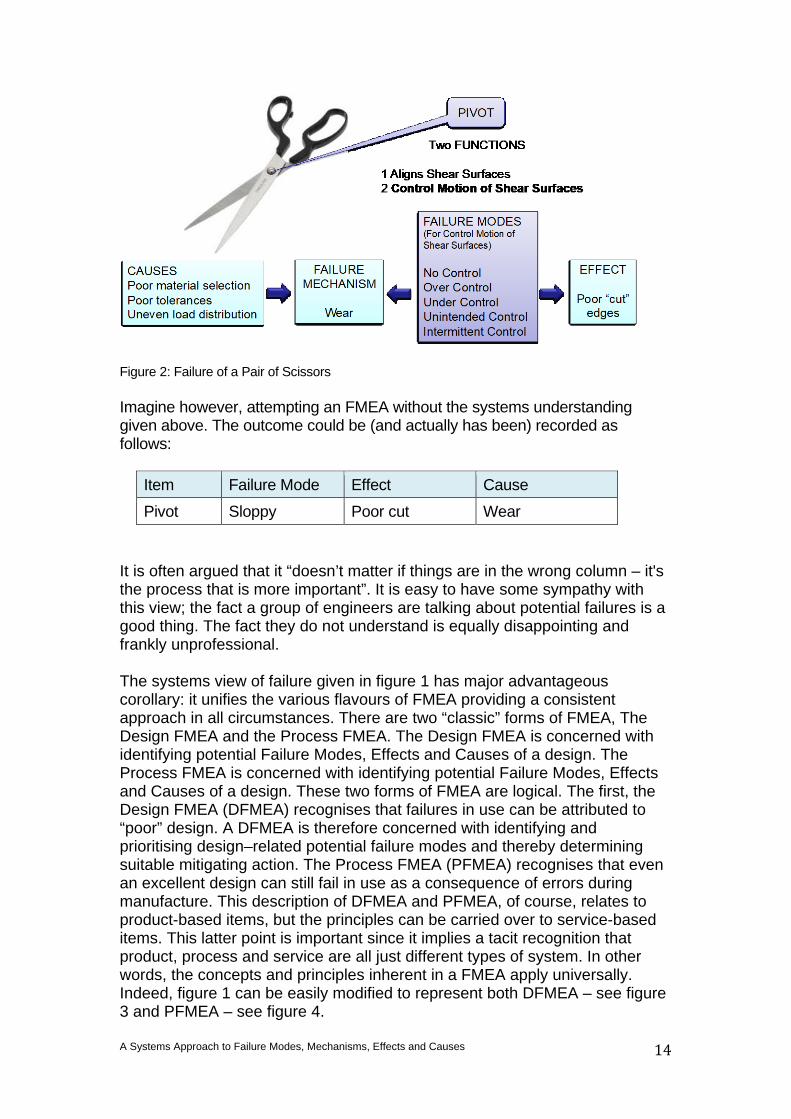
Figure 2: Failure of a Pair of Scissors Imagine however, attempting an FMEA without the systems understanding given above. The outcome could be (and actually has been) recorded as follows:
Item Failure Mode Effect Cause Pivot Sloppy Poor cut Wear
It is often argued that it “doesn’t matter if things are in the wrong column – it's the process that is more important”. It is easy to have some sympathy with this view; the fact a group of engineers are talking about potential failures is a good thing. The fact they do not understand is equally disappointing and frankly unprofessional. The systems view of failure given in figure 1 has major advantageous corollary: it unifies the various flavours of FMEA providing a consistent approach in all circumstances. There are two “classic” forms of FMEA, The Design FMEA and the Process FMEA. The Design FMEA is concerned with identifying potential Failure Modes, Effects and Causes of a design. The Process FMEA is concerned with identifying potential Failure Modes, Effects and Causes of a design. These two forms of FMEA are logical. The first, the Design FMEA (DFMEA) recognises that failures in use can be attributed to “poor” design. A DFMEA is therefore concerned with identifying and prioritising design–related potential failure modes and thereby determining suitable mitigating action. The Process FMEA (PFMEA) recognises that even an excellent design can still fail in use as a consequence of errors during manufacture. This description of DFMEA and PFMEA, of course, relates to product-based items, but the principles can be carried over to service-based items. This latter point is important since it implies a tacit recognition that product, process and service are all just different types of system. In other words, the concepts and principles inherent in a FMEA apply universally. Indeed, figure 1 can be easily modified to represent both DFMEA – see figure 3 and PFMEA – see figure 4.
A Systems Approach to Failure Modes, Mechanisms, Effects and Causes
15
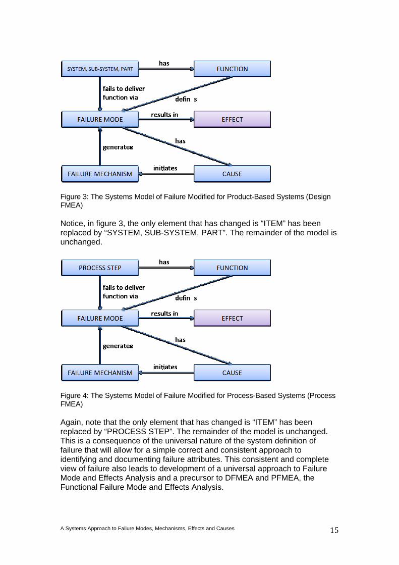
Figure 3: The Systems Model of Failure Modified for Product-Based Systems (Design FMEA) Notice, in figure 3, the only element that has changed is “ITEM” has been replaced by “SYSTEM, SUB-SYSTEM, PART”. The remainder of the model is unchanged.
Figure 4: The Systems Model of Failure Modified for Process-Based Systems (Process FMEA) Again, note that the only element that has changed is “ITEM” has been replaced by “PROCESS STEP”. The remainder of the model is unchanged. This is a consequence of the universal nature of the system definition of failure that will allow for a simple correct and consistent approach to identifying and documenting failure attributes. This consistent and complete view of failure also leads to development of a universal approach to Failure Mode and Effects Analysis and a precursor to DFMEA and PFMEA, the Functional Failure Mode and Effects Analysis.
A Systems Approach to Failure Modes, Mechanisms, Effects and Causes
16
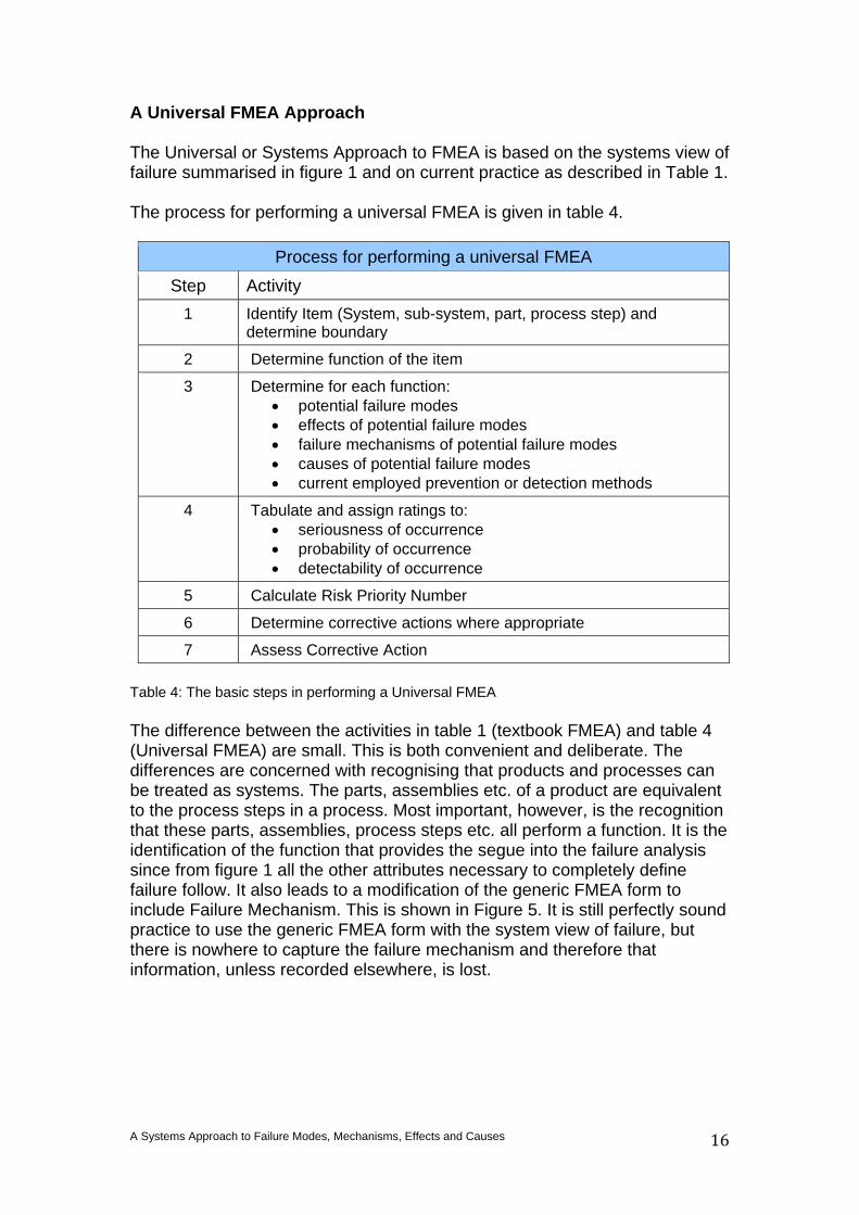
A Universal FMEA Approach The Universal or Systems Approach to FMEA is based on the systems view of failure summarised in figure 1 and on current practice as described in Table 1. The process for performing a universal FMEA is given in table 4.
Process for performing a universal FMEA Step Activity
1 Identify Item (System, sub-system, part, process step) and determine boundary
2 Determine function of the item
3 Determine for each function: • potential failure modes • effects of potential failure modes • failure mechanisms of potential failure modes • causes of potential failure modes • current employed prevention or detection methods
4 Tabulate and assign ratings to: • seriousness of occurrence • probability of occurrence • detectability of occurrence
5 Calculate Risk Priority Number
6 Determine corrective actions where appropriate
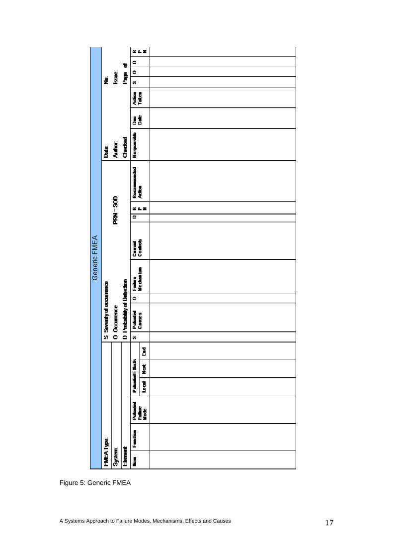
7 Assess Corrective Action Table 4: The basic steps in performing a Universal FMEA The difference between the activities in table 1 (textbook FMEA) and table 4 (Universal FMEA) are small. This is both convenient and deliberate. The differences are concerned with recognising that products and processes can be treated as systems. The parts, assemblies etc. of a product are equivalent to the process steps in a process. Most important, however, is the recognition that these parts, assemblies, process steps etc. all perform a function. It is the identification of the function that provides the segue into the failure analysis since from figure 1 all the other attributes necessary to completely define failure follow. It also leads to a modification of the generic FMEA form to include Failure Mechanism. This is shown in Figure 5. It is still perfectly sound practice to use the generic FMEA form with the system view of failure, but there is nowhere to capture the failure mechanism and therefore that information, unless recorded elsewhere, is lost.
A Systems Approach to Failure Modes, Mechanisms, Effects and Causes
17
Figure 5: Generic FMEA
A Systems Approach to Failure Modes, Mechanisms, Effects and Causes
18
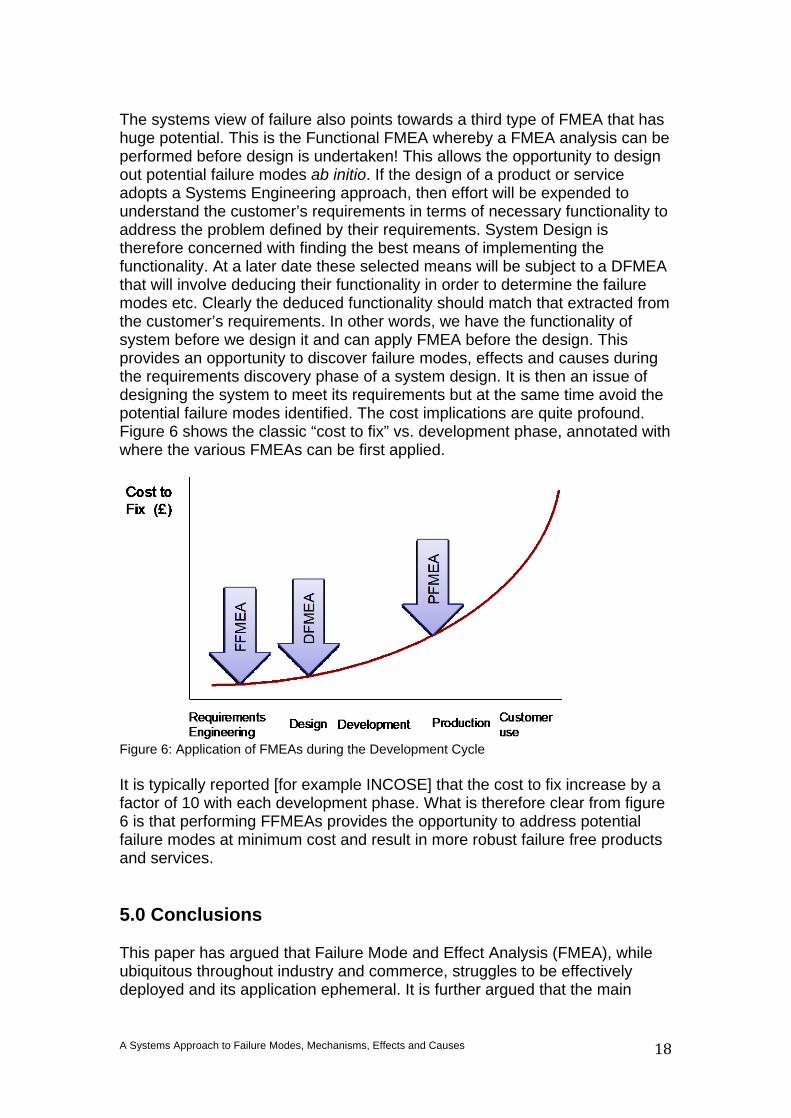
The systems view of failure also points towards a third type of FMEA that has huge potential. This is the Functional FMEA whereby a FMEA analysis can be performed before design is undertaken! This allows the opportunity to design out potential failure modes ab initio. If the design of a product or service adopts a Systems Engineering approach, then effort will be expended to understand the customer’s requirements in terms of necessary functionality to address the problem defined by their requirements. System Design is therefore concerned with finding the best means of implementing the functionality. At a later date these selected means will be subject to a DFMEA that will involve deducing their functionality in order to determine the failure modes etc. Clearly the deduced functionality should match that extracted from the customer’s requirements. In other words, we have the functionality of system before we design it and can apply FMEA before the design. This provides an opportunity to discover failure modes, effects and causes during the requirements discovery phase of a system design. It is then an issue of designing the system to meet its requirements but at the same time avoid the potential failure modes identified. The cost implications are quite profound. Figure 6 shows the classic “cost to fix” vs. development phase, annotated with where the various FMEAs can be first applied.
Figure 6: Application of FMEAs during the Development Cycle It is typically reported [for example INCOSE] that the cost to fix increase by a factor of 10 with each development phase. What is therefore clear from figure 6 is that performing FFMEAs provides the opportunity to address potential failure modes at minimum cost and result in more robust failure free products and services. 5.0 Conclusions This paper has argued that Failure Mode and Effect Analysis (FMEA), while ubiquitous throughout industry and commerce, struggles to be effectively deployed and its application ephemeral. It is further argued that the main
A Systems Approach to Failure Modes, Mechanisms, Effects and Causes
19
contributing factors are the over-exposure of FMEA in combination with a visceral understanding of failure. This paper has used concepts from Systems Thinking to provide a clear and consistent understanding of failure that in turn permits a repeatable and reproducible approach to FMEA whether it is Design or Process. This system approach to FMEA also points the way to the need to adopt an even earlier form of FMEA as a precursor to a Design FMEA and Process FMEA. The intent of what is called Functional FMEA is to identify issues before design commences such that they can be designed out ab initio. 6.0 References [1] BS4778-3.1:1991 Quality vocabulary. Availability, reliability and maintainability terms
Guide to concepts and related definitions [2] IEC 60050(191):1990, International Electrotechnical Vocabulary (IEV) – Chapter 191:
Dependability and quality of service [3] IEC 60812, 2006 Analysis techniques for system reliability – Procedure for failure
mode and effects analysis (FMEA) [4] Stamatis D.H. Failure Mode and Effect Analysis, ASQ Quality Press 2003 ISBN 0-
87389-598-3 [5] United States Department of Defense (24 November 1980). MIL-STD-1629A -
Procedures for performing a failure mode effect and criticality analysis. Department of Defense (USA). MIL-STD-1629A.
[6] AIAG (2008). Potential Failure Mode and Effect Analysis (FMEA), 4th Edition. Automotive Industry Action Group. ISBN 9781605341361.
[7] SAE (2008). Potential Failure Mode and Effects Analysis in Design (Design FMEA)
and Potential Failure Mode and Effects Analysis in Manufacturing and Assembly Processes (Process FMEA) and Effects Analysis for Machinery (Machinery FMEA). SAE International.
[8] Burge S E Holistic Requirements Model, Burge Hughes Walsh,
www.burgehugheswalsh.co.uk, 2012