A System Approach to D ynamic Characteristics of H...
12
IJISET - International Journal of Innovative Science, Engineering & Technology, Vol. 3 Issue 5, May 2016. www.ijiset.com ISSN 2348 – 7968 A System Approach to Dynamic Characteristics of Hanger Rod in Exhaust System Mylaudy Dr.S.Rajadurai 1 , R.Kavin 2 , Rejinjose 3 , Prabhakaran 4 , Rajeshraman 5 1 Head -Research & Development /Sharda Motor Industries Ltd, Chennai, State Tamil Nadu, India 2 Assistant Manager - Research & Development /Sharda Motor Industries Ltd, Chennai, State Tamil Nadu, India 3,4,5 Senior Engineer- Research & Development /Sharda Motor Industries Ltd, Chennai, State Tamil Nadu, India Abstract The first and foremost important prerequisite that a designer require to design a part is stiffness information. The dynamic characteristics of automotives exhaust hanger rods are studied for high frequencies at which the resonance vibration occurs, which is also an important transfer path for vibration to exhaust system. The point is to elaborate an approach which provides guidance towards optimized designs, mainly in early development stages. Theoretical and experimental modal analyses are used to suggest design parameters in terms of natural frequencies, which should be above 150 – 200Hz from the engine excitation frequency. Case studies are presented to show the methodology and validation of full system hanger rods for stiffness applications. The results acquired in this case study will highlight the potential applications of this approach, as well as the challenges associated with this method. Keywords: Hanger rod, Modal analysis, Design parameters, Experimental validation. 1. Introduction Effective and efficient product development is critical to corporate success on the increasingly competitive global market and simulation has proven to support this in many sectors. This translates in design ’first-time-right’ philosophy, where the use of advanced numerical and experimental methods that account for the product environment is essential. “What if” studies to understand the effects of changing geometrical parameters or to change a design parameter to avert failure and improve the product design is essentially known as design optimization. Design optimization provides a robust and systematic methodology by carefully studying the effects of various design variables and improves the design by varying the variables. Along with the load - deflection characteristics to understand the stiffness, the deformed shape of the component and the resulting stress-strain distribution can also be predicted. Noise and vibrations are indiscernible to the occupants of the car. The main source of vibration related to exhaust system is engine. There are mainly two transfer paths namely; structure and airborne vibrations. The structure borne paths starts from the engine and transmission line mounts and it transfers to the exhaust system through the hanger rod. Therefore, it is of great importance that the hangers are designed so that their natural frequencies are higher than the frequencies of the exiting sources acting on the system. Several papers dealing with the dynamic behavior of the whole exhaust system have been found [2-4], but no treatise of the hanger’s dynamic behavior has been found. The purpose of this paper is to analyze the design parameters of hangers that have affect on natural frequencies. Theoretical and experimental modal analysis will be performed for some existing. 450
Transcript of A System Approach to D ynamic Characteristics of H...
IJISET - International Journal of Innovative Science, Engineering & Technology, Vol. 3 Issue 5, May 2016.
www.ijiset.com
ISSN 2348 – 7968
A System Approach to Dynamic Characteristics of Hanger Rod in Exhaust System
Mylaudy Dr.S.Rajadurai1, R.Kavin2, Rejinjose3, Prabhakaran4, Rajeshraman5
1Head -Research & Development /Sharda Motor Industries Ltd,
Chennai, State Tamil Nadu, India
2Assistant Manager - Research & Development /Sharda Motor Industries Ltd, Chennai, State Tamil Nadu, India
3,4,5Senior Engineer- Research & Development /Sharda Motor Industries Ltd,
Chennai, State Tamil Nadu, India
Abstract
The first and foremost important prerequisite that a designer require to design a part is stiffness information. The dynamic characteristics of automotives exhaust hanger rods are studied for high frequencies at which the resonance vibration occurs, which is also an important transfer path for vibration to exhaust system. The point is to elaborate an approach which provides guidance towards optimized designs, mainly in early development stages. Theoretical and experimental modal analyses are used to suggest design parameters in terms of natural frequencies, which should be above 150 – 200Hz from the engine excitation frequency. Case studies are presented to show the methodology and validation of full system hanger rods for stiffness applications. The results acquired in this case study will highlight the potential applications of this approach, as well as the challenges associated with this method.
Keywords: Hanger rod, Modal analysis, Design parameters, Experimental validation.
1. Introduction
Effective and efficient product development is critical to corporate success on the increasingly competitive global market and simulation has proven to support this in many sectors. This translates in design ’first-time-right’ philosophy, where the use of advanced numerical and experimental methods that account for the product environment is essential.
“What if” studies to understand the effects of changing geometrical parameters or to change a design parameter
to avert failure and improve the product design is essentially known as design optimization. Design optimization provides a robust and systematic methodology by carefully studying the effects of various design variables and improves the design by varying the variables. Along with the load - deflection characteristics to understand the stiffness, the deformed shape of the component and the resulting stress-strain distribution can also be predicted.
Noise and vibrations are indiscernible to the occupants of the car. The main source of vibration related to exhaust system is engine. There are mainly two transfer paths namely; structure and airborne vibrations. The structure borne paths starts from the engine and transmission line mounts and it transfers to the exhaust system through the hanger rod. Therefore, it is of great importance that the hangers are designed so that their natural frequencies are higher than the frequencies of the exiting sources acting on the system.
Several papers dealing with the dynamic
behavior of the whole exhaust system have been found [2-4], but no treatise of the hanger’s dynamic behavior has been found. The purpose of this paper is to analyze the design parameters of hangers that have affect on natural frequencies. Theoretical and experimental modal analysis will be performed for some existing.
450
IJISET - International Journal of Innovative Science, Engineering & Technology, Vol. 3 Issue 5, May 2016.
www.ijiset.com
ISSN 2348 – 7968
2.Limitations
The main restraint is that all natural frequencies of the hangers must depend on vehicle applications. The excitation sources are assumed to vibrate the exhaust system up to frequency range from 100-250Hz for passenger car vehicles. The vendors demand includes a safety margin of 150-200Hz, which should be able to withstand the loads such as mechanical loads, thermal loads and corrosion characteristics.
Design parameters are influenced by mass and geometry. The materials used in all case studies are stainless steel grades (SS409.S10C). Stiffness depends on material mechanical properties, geometrical design and connections between hanger and the exhaust system, i.e. weld. The geometrical limitation of hanger rod, i.e. it should be able to fit the standard rubber isolators and should also meet the packaging conditions of the system. As a secondary solution, influencing the damping ratio of the isolator in the structure is possible to decrease the effects of natural frequencies that cannot be increased above the desired level. So, damping effects of rubber isolator will not be discussed in this paper.
3.Modal analysis theory
Modal analysis provides details about mode shapes, natural frequencies and damping ratios for the investigated structure. The analyses can be performed both as theoretical calculations on a FE-model and experimental tests on the real structures [5-7]. The damping ratios can only be determined experimentally. Theory is common for both theoretical and experimental modal analyses are described briefly below. 3.1.Theoretical modal analysis The basic equation for typical un-damped modal
analysis is classic Eigen value problem.
According to mode theory, the structure will be typically seen as a system constituted by the mass point, rigid body, damper and discrete it as finite number of elastic coupling rigid bodies.
Therefore, an infinite multi-degree of freedom
system turns into limited multi-degrees of freedom system.
When the linear time-invariant system requirements are met, the system’s general motion mathematical model can be expressed as:
M + C +Kx = f(t) (1)
Where, M, C, K: The mass matrix, damping matrix
and stiffness matrix x: The exhaust pipe vibration displacement
vector f (t) : The exhaust pipe load vector
Modal analysis method is to replace the physical
coordinates of modal coordinates that each principal mode corresponded, so that the differential equation decoupling to be independent differential equations in order to obtain the system modal parameters.
The vibration of the engine exhaust pipe is a random vibration, which basically belongs to linear time-invariant systems. It can be assumed that M is a constant matrix. The structural damping of exhaust pipe has little effect on the natural frequencies and therefore external load and damping are not considered.
Thus equation shown above becomes :
K- ω2 MΦ (2)
Where, M- ∫Ω ρNTNdΩ is the structure overall
quality matrix
When the order of matrix K and M is n, the ω2 in formula shown above is the n times real coefficient equation and the system degree of freedom vibration characteristics (natural frequencies and mode shapes) problem is to solve the matrix eigen value ω.
3.2.Experimental modal analysis
The modal properties are estimated from the frequency response functions (FRFs) obtained from the test data. In the FRF, a peak of the magnitude marks every resonance frequency. Each resonance frequency can be associated with a certain mode shape that represents the deflection shape of the structure [8]. There are several methods available for estimation of the mode shapes, both single and multiple degree of freedom methods. The estimation techniques, also called curve-fitting methods, are used to generate an analytical function that approximates the measured FRFs.
Inertance is the ratio of acceleration like quantity to a force like quantity, when the arguments of
451
IJISET - International Journal of Innovative Science, Engineering & Technology, Vol. 3 Issue 5, May 2016.
www.ijiset.com
ISSN 2348 – 7968
the real or imaginary parts of quantities increase linearly with time (dB reference 1ms-2/N).
Receptance is defined as displacement per unit
harmonic force. (dB reference 1m/N) Average displacement value of receptance plot
in the range of 200- 600Hz should be considered. 3.3.Correlation
Correlation is a process where data from the experiment are compared with theoretical results. There are several methods available, which are more or less complicated. Two graphical methods are “Graphical comparison of natural frequencies” and “Graphical comparison of mode shapes”. They are easy to use, but they are very time consuming for models with many nodes. Two numerical methods for comparison of mode shapes are the “Modal scale factor” and the “Modal assurance criterion”.
The methods are briefly explained below. For a more complete discussion the reader is referred to for example Maia [9].
4.Methodology This paper includes full exhaust system hanger rods as subject, which was pre-processed using Hypermesh software, which was developed with the use of shell, solid, bush and rigid elements. Exhaust pipes, hanger rods, sub-resonator, main resonator and tail pipe are modeled with 4 noded shell elements. Inlet flange modeled with 8 noded Hexa elements. Flexible bellows and rubber isolators are modeled with bush elements and necessary stiffness values are assumed as per available references. Schematic representation of the system is shown below in the Figure 3. The natural frequency, static response and frequency response stress are determined from Normal modes, Static 1G and Durability analysis. These are performed using Msc Nastran and the results are posted using Hyperview. The results are compared and correlated with experimental data using NVH and Fatigue lab. 4.1.Analysis simulated for structural validity
Stiffness analysis - To determine the natural stiffness of the hanger rods.
Static 1G loading - System stability, hanger forces and hanger displacements.
Resonance frequency analysis - Determining the mode shape behaviour of the system and checking for resonance.
Engine Roll + 4⁰ analyses - To check the bellows relative displacement, bending moment at the inlet of the main resonator, inlet and outlet of the sub- resonator.
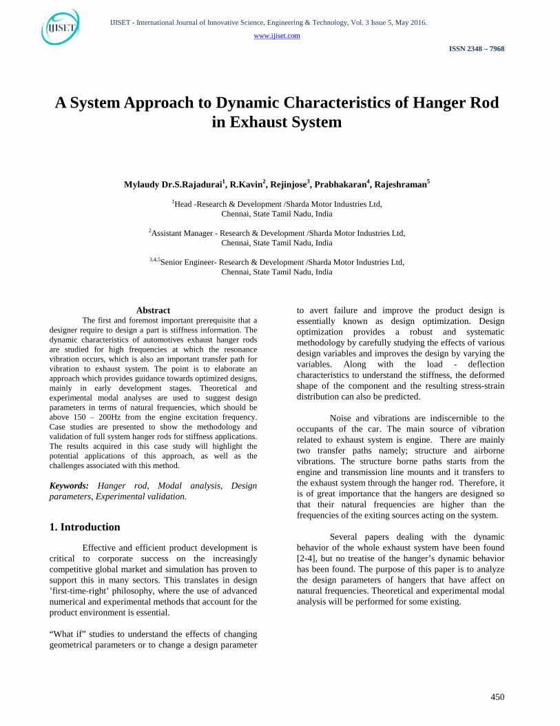
Figure 1. System overview
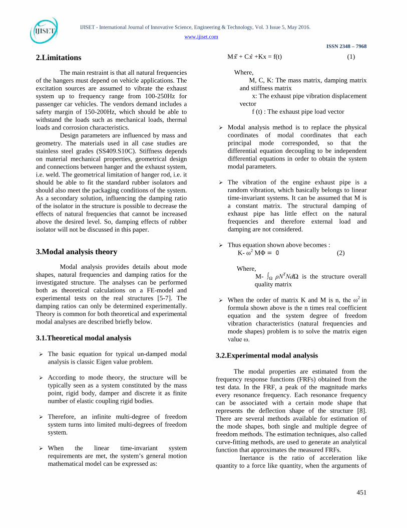
Figure 2. Hanger 1, 2 and 3 4.2.Input details
No of Cylinders = 3
Engine Rated Speed = 6000 rpm
Natural Frequency from engine rated speed = (6000/60) * (3/2)
= 150Hz
4.2.1.Criteria
From the engine excitation frequency with a safety margin of 150% which was mentioned above, criteria was set to 375 Hz for first mode frequency. But a constraint like diameter of the hanger rod is set by
452
IJISET - International Journal of Innovative Science, Engineering & Technology, Vol. 3 Issue 5, May 2016.
www.ijiset.com
ISSN 2348 – 7968
vendor. So, only the geometrical aspect of the design is analyzed and validated.
4.2.2.Materials property
Linear material properties in cold condition like Young’s modulus, density, and Poisson ratio are considered.
Table 1. Material properties
Materials Young
modulus N/mm2
Poisson ratio
Density Ton/mm3
SS409 2.08e05 0.3 7.7e-09
S10C 2.0e05 0.29 7.84e-09
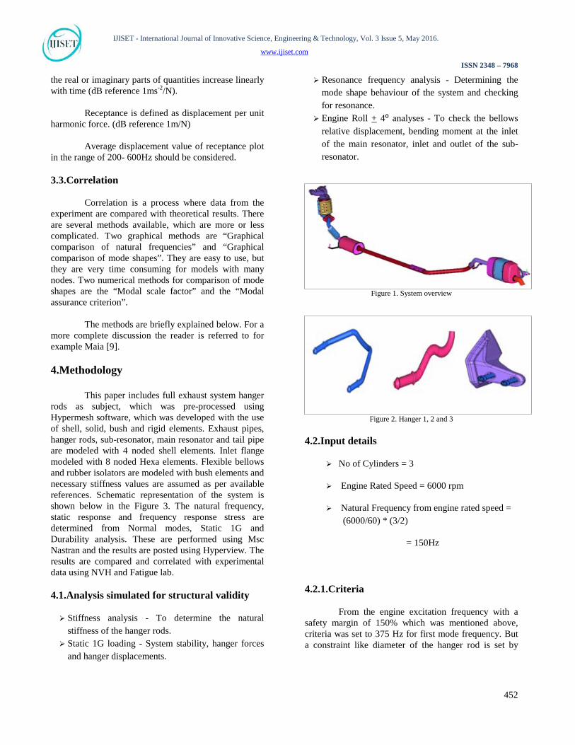
4.2.3. Analysis process flow
Figure 3. Process flow
4.2.4.Boundary conditions
Table 2.Weld length and hanger type
Hangers Type Materials Weld length(mm)
Hanger 1 Solid S10C 60*2 Hanger 2 Hollow SS409 80*2
Hanger 3 Bracket with hanger SS409 60
25
All weld nodes of hanger rod and bracket with hanger rod are constrained in all degrees of freedom, which are represented by the Figure 4 shown below
Figure 4. Weld nodes constrained in all d.o.f
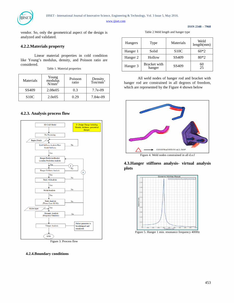
4.3.Hanger stiffness analysis- virtual analysis plots
Figure 5. Hanger 1 min. resonance frequency 400Hz
453
IJISET - International Journal of Innovative Science, Engineering & Technology, Vol. 3 Issue 5, May 2016.
www.ijiset.com
ISSN 2348 – 7968
Figure 6. Hanger 2 min. resonance frequency 700Hz
Figure 7. Hanger 3 min. resonance frequency 635Hz
4.3.1.Observations
It has been observed that Hanger rod’s stiffness is above the targeted natural frequency of 375 Hz.
It has been concluded that Static analysis,
Modal analysis have to be performed to check the resonance frequency, hanger forces, stresses and deformations for validating the hanger rod design.
4.4.Impact testing
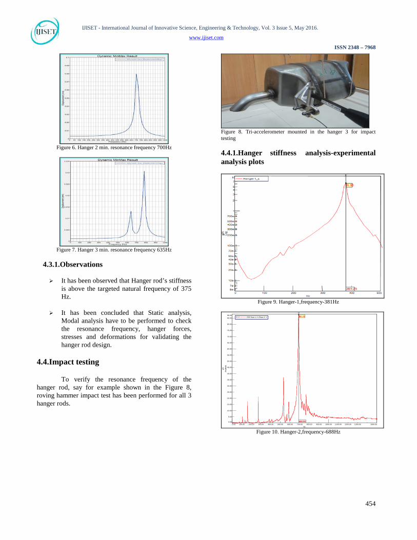
To verify the resonance frequency of the hanger rod, say for example shown in the Figure 8, roving hammer impact test has been performed for all 3 hanger rods.
Figure 8. Tri-accelerometer mounted in the hanger 3 for impact testing
4.4.1.Hanger stiffness analysis-experimental analysis plots
Figure 9. Hanger-1,frequency-381Hz
1500.000.00 1000.00500.00100.00 200.00 300.00 400.00 600.00 700.00 800.00 900.00 1100.00 1200.00 1300.00Hz
88.00
0.00
10.00
20.00
30.00
40.00
50.00
60.00
70.00
80.00
5.00
15.00
25.00
35.00
45.00
55.00
65.00
75.00
85.00
Ampli
tude
g/N
688.50
87.72F FRF Point 1:+Y/Point 2:-Y
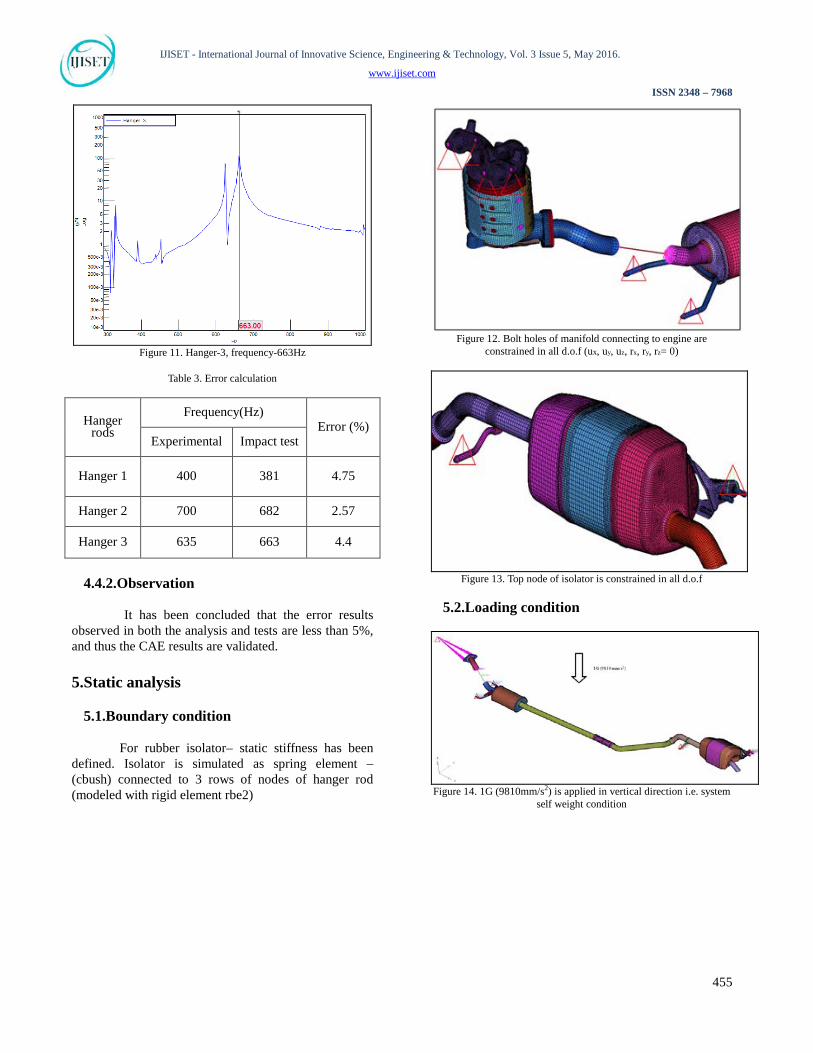
Figure 10. Hanger-2,frequency-688Hz
454
IJISET - International Journal of Innovative Science, Engineering & Technology, Vol. 3 Issue 5, May 2016.
www.ijiset.com
ISSN 2348 – 7968
Figure 11. Hanger-3, frequency-663Hz
Table 3. Error calculation
Hanger rods
Frequency(Hz) Error (%)
Experimental Impact test
Hanger 1 400 381 4.75
Hanger 2 700 682 2.57
Hanger 3 635 663 4.4
4.4.2.Observation
It has been concluded that the error results observed in both the analysis and tests are less than 5%, and thus the CAE results are validated. 5.Static analysis
5.1.Boundary condition
For rubber isolator– static stiffness has been defined. Isolator is simulated as spring element – (cbush) connected to 3 rows of nodes of hanger rod (modeled with rigid element rbe2)
Figure 12. Bolt holes of manifold connecting to engine are
constrained in all d.o.f (ux, uy, uz, rx, ry, rz= 0)
Figure 13. Top node of isolator is constrained in all d.o.f
5.2.Loading condition
Figure 14. 1G (9810mm/s2) is applied in vertical direction i.e. system
self weight condition
455
IJISET - International Journal of Innovative Science, Engineering & Technology, Vol. 3 Issue 5, May 2016.
www.ijiset.com
ISSN 2348 – 7968
5.3.Static plots
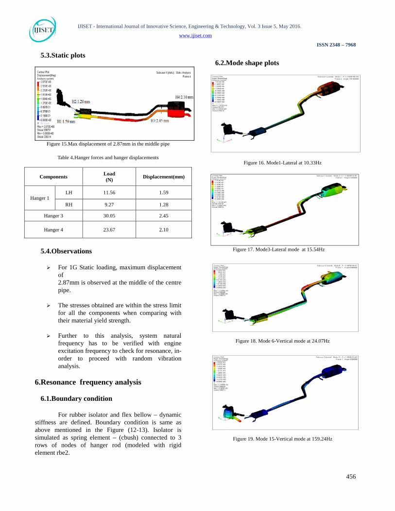
Figure 15.Max displacement of 2.87mm in the middle pipe
Table 4.Hanger forces and hanger displacements
Components Load (N) Displacement(mm)
Hanger 1 LH 11.56 1.59
RH 9.27 1.28
Hanger 3 30.05 2.45
Hanger 4 23.67 2.10
5.4.Observations For 1G Static loading, maximum displacement
of 2.87mm is observed at the middle of the centre pipe.
The stresses obtained are within the stress limit
for all the components when comparing with their material yield strength.
Further to this analysis, system natural
frequency has to be verified with engine excitation frequency to check for resonance, in-order to proceed with random vibration analysis.
6.Resonance frequency analysis
6.1.Boundary condition
For rubber isolator and flex bellow – dynamic stiffness are defined. Boundary condition is same as above mentioned in the Figure (12-13). Isolator is simulated as spring element – (cbush) connected to 3 rows of nodes of hanger rod (modeled with rigid element rbe2.
6.2.Mode shape plots
Figure 16. Mode1-Lateral at 10.33Hz
Figure 17. Mode3-Lateral mode at 15.54Hz
Figure 18. Mode 6-Vertical mode at 24.07Hz
Figure 19. Mode 15-Vertical mode at 159.24Hz
456
IJISET - International Journal of Innovative Science, Engineering & Technology, Vol. 3 Issue 5, May 2016.
www.ijiset.com
ISSN 2348 – 7968
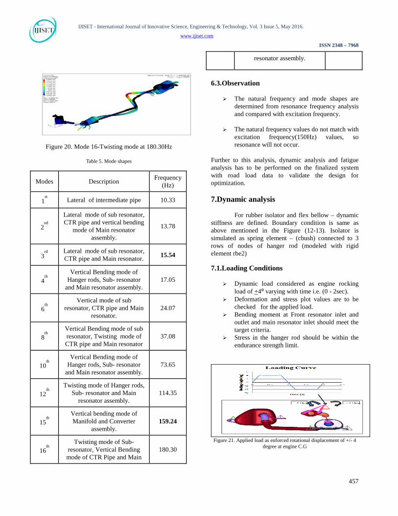
Figure 20. Mode 16-Twisting mode at 180.30Hz
Table 5. Mode shapes
Modes Description Frequency (Hz)
1st Lateral of intermediate pipe 10.33
2nd
Lateral mode of sub resonator, CTR pipe and vertical bending
mode of Main resonator assembly.
13.78
3rd
Lateral mode of sub resonator, CTR pipe and Main resonator. 15.54
4th
Vertical Bending mode of Hanger rods, Sub- resonator
and Main resonator assembly. 17.05
6th
Vertical mode of sub resonator, CTR pipe and Main
resonator. 24.07
8th
Vertical Bending mode of sub resonator, Twisting mode of CTR pipe and Main resonator
37.08
10th
Vertical Bending mode of Hanger rods, Sub- resonator
and Main resonator assembly. 73.65
12th
Twisting mode of Hanger rods, Sub- resonator and Main
resonator assembly. 114.35
15th
Vertical bending mode of Manifold and Converter
assembly. 159.24
16th
Twisting mode of Sub- resonator, Vertical Bending
mode of CTR Pipe and Main 180.30
resonator assembly.
6.3.Observation
The natural frequency and mode shapes are determined from resonance frequency analysis and compared with excitation frequency.
The natural frequency values do not match with excitation frequency(150Hz) values, so resonance will not occur.
Further to this analysis, dynamic analysis and fatigue analysis has to be performed on the finalized system with road load data to validate the design for optimization. 7.Dynamic analysis
For rubber isolator and flex bellow – dynamic stiffness are defined. Boundary condition is same as above mentioned in the Figure (12-13). Isolator is simulated as spring element – (cbush) connected to 3 rows of nodes of hanger rod (modeled with rigid element rbe2)
7.1.Loading Conditions
Dynamic load considered as engine rocking load of +4⁰ varying with time i.e. (0 - 2sec).
Deformation and stress plot values are to be checked for the applied load.
Bending moment at Front resonator inlet and outlet and main resonator inlet should meet the target criteria.
Stress in the hanger rod should be within the endurance strength limit.
Figure 21. Applied load as enforced rotational displacement of +/- 4
degree at engine C.G
457

IJISET - International Journal of Innovative Science, Engineering & Technology, Vol. 3 Issue 5, May 2016.
www.ijiset.com
ISSN 2348 – 7968
Figure 22. Stress plots
7.3.Observation Maximum Von-mises stresses of 85MPa
observed in the bend region of the intermediate pipe. And von misses stress of 60MPa near the weld regions of hanger 1.
It has been concluded that the system satisfies the durability requirements under engine roll loading condition.
Dynamic stresses are compared with the acceptable limit of the materials. Since the Power-train translation and the engine vibration loading have a high number of cycles, the Von-mises stresses were judged against endurance limit of the material at the respective temperature for expected life. Empirical formulas were used to convert the ultimate strength to endurance limit. Number of cycles to failures observed in testing (life of the system) justifies the stress level predicted in the analysis.
8.Validation
The exhaust system models were validated by comparing the natural frequencies and modes of the FE model to the experimentally measured values. To calculate the natural frequencies, modal analysis was performed with the preloading effect to capture accurate behavior of system. The modal strain energy distribution was used to identify the critical locations. These critical locations were refined in the model to meet stress convergence criteria before full dynamic analysis. Table 3 shows theoretical and experimental modal analysis results for the exhaust system. It shows good agreement with the testing and CAE evaluation.
8.1.Durability test
Maximum load that may act on the exhaust system during its service life may be derived from RLDA.
RLDA input can be used for accelerated validation of exhaust system durability by component wise.
RLDA is very important to derive whether the system will meet the end usage durability target or not.
Usually, the load is acquired for Hanger rod is in the vertical direction (Fz).
8.2.Analysis and test setup
To carry out the test, hanger rods are fixed in the same direction as it is mounted in the chassis.
To interpret the same position, hanger rods was fixed as shown in the Figure (26-28) below. From damage comparison, the drive file generated by Belgian block was considered. Drive file was applied to vehicle’s vertical (Z) direction.
Uni-axial actuator is connected to the hanger rod in which the force Fz is applied.
Figure 23. Fz applied-hanger 1
Figure 24. Fz applied-hanger 2
458

IJISET - International Journal of Innovative Science, Engineering & Technology, Vol. 3 Issue 5, May 2016.
www.ijiset.com
ISSN 2348 – 7968
Figure 25. Fz applied-hanger 3
8.3.Test result
The test profile was repeated to pre-defined cycles to simulate the durability target. After the test, the hanger rods showed no defects.
Figure 26. Test setup-hanger 1
Figure 27. Test setup-hanger 2
Figure 28. Test setup-hanger 3
Figure 29. Drive file-hanger 1
Figure 30. Drive file-hanger 2
Figure 31. Drive file-hanger 3
9.Design improvement
In order to make the design optimization in the hanger rods 2 & 3, parameters like diameter, thickness and types can be altered. Stress results should be compared for initial design and modified design in same locations. Need to evaluate the dynamic analysis of initial design and improved design to predict the induced stresses which should be within acceptable limits of the material.
10.Conclusion
The detailed analysis approach developed in this study will help the engineers to predict the stiffness and durability performance of the exhaust system and develop a better exhaust system with quick turnaround time. Application of measured excitations, assembly loads and effects of manufacturing inaccuracies in dynamic analysis has shown enhancement in predicting
459
IJISET - International Journal of Innovative Science, Engineering & Technology, Vol. 3 Issue 5, May 2016.
www.ijiset.com
ISSN 2348 – 7968
the performance of exhaust system. Material properties change significantly with temperature; material stiffness is reduced by the increased temperature and has effect on the vibration characteristics.
It is possible to identify the failure locations and find out solution for the problem. The results obtained assure the structural integrity of the modified exhaust system when implemented on the vehicle. This methodology also contributes to a better understanding of system behavior and its structural strength, for future project applications. The same approach can also be extended to analysis of exhaust system resonator shell, baffles, end cap, heat shield and mounting brackets.
Acknowledgement The authors wish to thank Sharda Motor
Industries Ltd - R&D Centre for offering and supporting the opportunity to document and present this paper.
References [1] ASME 2003. ASME Manual MS-4, An ASME Paper,
latest ed. The American Society of Mechanical Engineers, New York. See also URL http://www.asme.org/pubs/MS4.html
[2] Helms.H, 1989. “Investigation of Vibration, oscillation
and Noise in the Car Test”. International Journal. of Vehicle Design, Vol. 10, no. 6, UK.
[3] Belingardi G. and Leonti S, 1987. “Modal Analysis in the
Design of An Automotive Exhaust Pipe”. International Journal. of Vehicle Design, Vol. 8, no. 4/5/6, UK.
[4] Shih-Fu Ling, Tso-Chein Pan, Geok- Hian Lim and
Ching-Huan Tseng,1994. “Vibration Isolation of Exhaust Pipe Under Vehicle Chassis”. International Journal. of Vehicle Design, Vol. 15, nos.1/2, UK.
[5] Eriksson.L.J and Thawani.P.T,1985. “Theory and Practice
in Exhaust System Design”. SAE 850989. [6]Masters thesis,Kadam.V.V,2000. “Modal Analysis and
Hanger Design Optimization of Exhaust System for Utility Vehicle by using Finite Element Method”. SGGS College of Engineering, Ann-University-Nanded, India.
[7] Nastran “Theory of Real Eigen value Analysis” on page
101
[8] LMS “LMS test lab, Rev 13A Service Level 1-Manual”. See also URL www.lmsintl.com
[9] Maia N. N. M., Silva J. M. M., He J., Lieven N. A. J., Lin R. M., Skingle G. W., To W. M., Urgueria A. P. V.,1997. “Theoretical and Experimental Modal Analyst’. Research Studies Press Ltd, Somerset.
Dr.S.Rajadurai,Ph.D. born in Mylaudy, Kanyakumari District, Tamil Nadu, India, received his Ph.D. in Chemistry from IIT Chennai in 1979. He has devoted nearly 35 years to scientific innovation, pioneering theory and application through the 20th century, and expanding strides of advancement into the 21st century. By authoring hundreds of published papers and reports and creating several patents, his research on solid oxide solutions, free radicals, catalyst structure sensitivity, and catalytic converter and exhaust system design has revolutionized the field of chemistry and automobile industry.Dr. Rajadurai had various leadership position such has the Director of Research at Cummins Engine Company, Director of Advanced Development at Tenneco Automotive, Director of Emissions at ArvinMeritor, Vice-President of ACS Industries and since 2009 he is the Head of R&D Sharda Motor Industries Ltd. He was a panelist of the Scientists and Technologists of Indian Origin, New Delhi 2004. He is a Fellow of the Society of Automotive Engineers. He was the UNESCO representative of India on low-cost analytical studies (1983-85). He is a Life Member of the North American Catalysis Society, North American Photo Chemical Society, Catalysis Society of India, Instrumental Society of India, Bangladesh Chemical Society and Indian Chemical Society. Second Author: Kavin R, Assistant Manager - Structural Analysis at Sharda Motor Industries Limited, R&D centre, Chennai, for the past 4 years. Mr. Kavin holds a bachelor degree from Anna University, Tirunelveli.
During his career, Mr. Kavin has been involved in FE model building and assembly, solver input deck preparation and CAE structural analysis such as Modal, Static, and Dynamic & Thermal stress simulations for exhaust system hot end, cold end and full system. Team Lead for Structural analysis team. He published 5 SAE technical papers and also more than international 6 journals. He won 3rd prize in 2013 - Altair technology conference, Pune for paper titled on” Passenger car Exhaust system Muffler Bead Optimization and Comparative study using OptiStruct”. Area of interest includes Engine and power train, Project/product management,Techno-commercial activities, Product design, structural analysis, fatigue /durability analysis, experimental/operational modal analysis. Future plans include develop my experience and expertise in dynamic analysis (modal and transient frequency response), fatigue or durability analysis on Exhaust system and acoustic simulation of muffler. The objective of concentration is to move towards
460
IJISET - International Journal of Innovative Science, Engineering & Technology, Vol. 3 Issue 5, May 2016.
www.ijiset.com
ISSN 2348 – 7968
experimental testing such as tensile, compression, component fatigue, Full exhaust system fatigue, experimental modal analysis, NVH analysis and correlation with FEA simulation Third Author: Rejin Jose.J, Senior Engineer - Structural analysis Department at Sharda Motor Industries Limited, R&D centre, Chennai, holds a Bachelor degree in Mechanical Engineering from Anna University, Chennai and completed Bachelor’s thesis about exhaust system joints of automobiles. During his career Mr. Rejin Jose. J, has been involved in validation of exhaust system joints, coordinating material testing, advanced development works like hanger rod weld life prediction and mutually coordinated the developing Road Load Data Acquisition (RLDA) and Road Load Reproduction Test procedure to validate the exhaust systems. He has been involved in performing finite element modeling and analysis including Modal, Static, Dynamic, Fatigue, and Thermal. Mainly, He concentrates in Fatigue Analysis by utilizing commercially available FEA tools. Also he focused in development of new CAE capabilities, methodologies and expertise by staying aware to trends in the computational technology fields. He is also published research papers in technical conferences and international journals.
461