A Synopsis of Ion Propulsion Development Projects in … · A Synopsis of Ion Propulsion...
24
NASA/TM--1999-209439 AIAA 99-2270 A Synopsis of Ion Propulsion Development Projects in the United States: SERT I to Deep Space I James S. Sovey, Vincent K. Rawlin, and Michael J. Patterson Glenn Research Center, Cleveland, Ohio Prepared for the 35th Joint Propulsion Conference and Exhibit cosponsored by the AIAA, ASME, SAE, and ASEE Los Angeles, California, June 20-24, 1999 National Aeronautics and Space Administration Glenn Research Center October 1999 https://ntrs.nasa.gov/search.jsp?R=19990116725 2018-07-06T15:11:08+00:00Z
Transcript of A Synopsis of Ion Propulsion Development Projects in … · A Synopsis of Ion Propulsion...

NASA/TM--1999-209439 AIAA 99-2270
A Synopsis of Ion Propulsion Development
Projects in the United States:
SERT I to Deep Space I
James S. Sovey, Vincent K. Rawlin, and Michael J. PattersonGlenn Research Center, Cleveland, Ohio
Prepared for the
35th Joint Propulsion Conference and Exhibit
cosponsored by the AIAA, ASME, SAE, and ASEE
Los Angeles, California, June 20-24, 1999
National Aeronautics and
Space Administration
Glenn Research Center
October 1999
https://ntrs.nasa.gov/search.jsp?R=19990116725 2018-07-06T15:11:08+00:00Z

NASA Center for Aerospace Information7121 Standard Drive
Hanover, MD 21076Price Code: A03
Available from
National Technical Information Service
5285 Port Royal Road
Springfield, VA 22100Price Code: A03
A Synopsis of Ion Propulsion Development Projects in the United States:
SERT I to Deep Space
James S. Sovey, Vincent K. Rawlin. and Michael J. Patterson
National Aeronautics and Space AdministrationGlenn Research Center
Cleveland, Ohio 44135
Abstract GSFC
HS
HughesThe historical background and characteristics of
the experimental flights of ion propulsion
systems and the major ground-based technology HVdemonstrations were reviewed. The results of the IAPS
first successful ion engine flight in 1964, SERTI which demonstrated ion beam neutralization, are IPS
discussed along with the extended operation of JPL
SERT II starting in 1970. These results together LeRC
with the technology employed on the early NSSK
cesium engine flights, the ATS series, and the NSTAR
ground-test demonstrations, have provided the
evolutionary path for the development of xenon
ion thruster component technologies, control PAS
systems, and power circuit implementations. In PPU
the 1997-1999 period, the communication rms
satellite flights using ion engine systems and the RPM
Deep Space I flight confirmed that these SATMEX
auxiliary and primary propulsion systems have S/C
advanced to a high-level of flight-readiness. SCATHA
Acronyms and Abbreviations SEPS
A communication satellite
built by Hughes for SES
Applications TechnologySatellite
Breadboard Power ProcessingUnit
Defense Advanced Research
Projects Agency
Digital Control and InterfaceUnit
Deep Space IEngineering Model
Electromagnetic Interference
Electro Optical Systems
East-West StationkeepingAcceleration due to Earth's
gravity, 9.807 m/s 2Glenn Research Center
ASTRA 2A
ATS
BBPPU
DARPA
DCIU
DS1
EM
EM1
EOS
EWSK
g
GRC
SEPST
SES
SERTSIT
SNAP
SNAPSHOT
SPIBS
ST4
USAF
XIPS
Gc,ddard Space Flight Center
Hughes Spacecraft
Hughes Space andCommunications Company
High Voltage
Ion Auxiliary Propulsion
System
Ion Propulsion System
Jet Propulsion LaboratoryLewis Research Center
North-South StationkeepingNASA Solar Electric
Propulsion Technology
Applications Readiness
PanAmSat Corporation
Power Processing Unit
root mean squareRevolutions Per Minute
Satmcx of Mexico Company
Spacecraft
Spacecraft Charging at HighAltitude
Solar Electric Propulsion
System
Solar Electric Propulsion
System Technology
Societe Europeenne des
Satellites of Luxembourg
Space Electric Rocket Test
Structurally Integrated Thruster
Systems for Nuclear AuxiliaryPower
Spacecraft carrying the SNAP
10A nuclear power supply and
a cesium ion propulsion
systemSatellite Positive-lon-Beam
System
Space Technology 4United States Air Force
Xenon Ion Propulsion System
NASA/TM-- 1999-209439 1
Introduction
Kilowatt-class ion propulsion systems have
found applications tbr spacecraft North-South
stationkeeping, orbit insertion, and primary
propulsion for deep space missions._'2 The first
successful ion propulsion flight system was
demonstrated in 1964 during the course of the
SERT I flight. 3 Later on seven more ion
propulsion systems and one ion source systemwere flown as space experiments using mercury,
cesium, or xenon expellants. A total of six
successful, operational flights of IPS are now in
use for NSSK or primary propulsion. Articles
on the origins of ion propulsion can be found inReferences 4 and 5.
Surveys of the history of electric propulsion
systems have cataloged the evolution of IPS
technology and generally described many of theexperimental and operational flights. _ The
purpose of this paper is to provide more detail
related to the IPS flights and major grounddemonstrations of the technology. Back_ound
on system perlbrmance and in-space operationwill be summarized, and the evolution of
electron-bombardment ion thruster developmentin the United States will be discussed.
Experimental Fli_hts of Ion
Pronulsions Systems
The experimental flights of ion propulsion
systems developed in the United States aresummarized. Some of the results indicated in the
Tables Ia and I b are expanded, and major results
are described. Although there were maior ground
test and development programs associated with
each of the experimental flights, nearly all of the
synopsized results reported here are associated
'with the end product which is the flight test.
pro2ram 661A. Test Code A
In November of 1961, Electro-Optical Systems
was awarded a contract by the U. S. Air Force to
develop a 8.9 mN, cesium contact ion propulsion
system ['or three sub-orbital flight tests. The
Electric Propulsion Space Tests were called
Program 661A and were managed by the Air
Force Space Systems Command in Los
Angeles. l"-_-'
The cesium contact engine incorporated an
ionizer array of 84 porous tungsten buttons. The
power level, thrust, and specific impulse were
0.77 kW, 8.9 mN, and 7400 s, respectively in
this engine which had a beam extraction diameterof about 7 cm. The neutralizer was a wire
filament which was not immersed in the ion
beam. Power to the PPU was supplied by 56 V
batteries. The longest ground test was 1230hours.
The first sub-orbital flight test was launched on
December 18, 1962. When the high-voltage
power supplies were first turned-on, intermittent
high-voltage breakdowns occurred, and the beam
power supply became inoperative. Post-flight
examination of the power supply indicated the
high-voltage breakdowns were probably caused
by pressure buildup in the PPU due to gas vented
from the spacecraft batteries. The PPU high-
voltage section was not adequately vented to keep
the pressure low enough. Engine thrusting was
not accomplished in this test.
SERTI
The SERT I spacecraft was launched July 20,
1964 using a Scout vehicle. __3 This flight
experiment had a 8 cm diameter cesium contact
ion engine and a 10 cm mercury electron
bombardment ion engine and was the first
successful flight test of ion propulsion. The
cesium engine was designed to operate at 0.6 kW
and provide 5.6 naN of thrust and a specific
impulse of 8050 s. The cesium flow was
controlled by a boiler and the porous tungstenionizer electrode. The 10 cm diameter mercury
engine provided flow control via a boiler and a
porous stainless steel plug. A hot tantalum wire
was used as the discharge cathode. Beam and
accelerator power supply voltages were 2500 V
and 2000 V, respectively. The engine had a 1.4
kW power level with 28 mN of thrust at a
specific impulse of about 4900 s. Ion beamneutralization was provided by a heated tantalumfilament.
The early part of the flight was dedicated to
attempts to operate the cesium engine. The
cesium engine could not be started because of a
high-voltage electrical short circuit. The mercury
engine was started about 14 minutes into theflight. The IPS was successfully operated for
NASA/TM--1999-209439 2
31minuteswith53high-voltagerecycleeventswhichwerehandledbythePPUfaultprotectionsystem.Eachoftherecycleeventsis onlyat;ewsecondsduration.Majorresultsfromthetestwerethefirstdemonstrationof anIPSin space,effectiveionbeamneutralization,noEMIeffectson other spacecraftsystems,and effectiverecoveryfromelectricalbreakdowns.Thrustwasmeasuredusing threeindependentmeasuringsystems,andtherewereno majordifferencesbetweenin-spaceandgroundtestperformance.
program 661A. Test Code B
Test Code B was the second in the series of three
suborbital flight tests of the Electro Optical
Systems' 8.9 mN, cesium ion engine
systems. "'H A Scout vehicle launched the
payload on August 29, 1964. The launch was
designed to provide about 30 minutes above analtitude of 370 km. Alter 7 minutes into the
flight, the engine was operated with ion beamextraction. Full beam current of 94 mA was
achieved about 10 minutes later. During the
course of engine operation, an electric field
strength meter was used to infer payload floating
potential relative to space. Spacecraft potential
was about 1000 V negative during most of the
engine operation with the filament neutralizer.
The absolute value of payload potential was
about ten times higher than anticipated, and it is
suspected that there was inadequate neutralization
of the ion beam. The contact ion engine operated
lbr approximately 19 minutes until spacecraft re-
entry into the atmosphere.
In addition to withstanding the environmental
rigors of space flight, the IPS demonstrated
electromagnetic compatibility with other
spacecraft subsystems and the ability to regulateand control a desired thrust level.
Program 661A. Test Code C
The third and final IPS payload of the Air Force's
Program 661A was launched on December 2t,1964. __'* In this test, an additional wire
neutralizer was incorporated and was immersed in
the ion beam to provide a higher probability of
adequate neutralization. The contact ion engine
only achieved about 20% of full-thrust before re-
entry into the atmosphere. The short test timewas due to a very short burn of the Scout
vehicle's third stage. The high voltage was
applied to the engine 7 minutes into the flight
when the altitude was 490 km. Engine operation
ended after 4 minutes when the altitude was only80 kin.
SNAPSHOT
On April 3, 1965 a SNAP 10A nuclear power
system was launched into a 1300 km orbit with acesium ion engine as a secondary payload. _5-_7
The ion beam power supply was operated at
4500 V and 80 mA to produce a thrust of about8.5 mN. The neutralizer was a barium-oxide
coated wire filament. The ion engine was to be
operated off batteries tbr about one hour, and then
the batteries were to be charged lbr approximately
15 hours using 0.1 kW of the nominal 0.5 kW
SNAP system as the power supply. The SNAP
power system operated successfully for about
43 days, but the ion engine operated for a period
of less than I hour betbre being commanded off
permanently. Analysis of flight data indicated a
significant number of high-voltage breakdowns
which apparently caused sufficient EMI to induce
false horizon sensor signals which created severe
attitude perturbations of the spacecraft. Ground
tests indicated that the engine arcing produced
conducted and radiated EMI significantly above
design levels. It was concluded that low
frequency, < 1 MHz, conducted EMI caused the
slewing of the spacecraft.
aTS-4
Two cesium contact ion engines were launched
aboard the ATS-4 spacecraft on August 10, 1968.
Flight test objectives were to measure thrust and
to examine electromagnetic compatibility with
other spacecraft subsystems/'mr" The 5 cm
diameter thrusters were designed to operate at
0.02 kW and provide about 89 _aN thrust at about
6700 s specific impulse. Thrusters had the
capability to operate at 5 setpoints from 18 [aN
to 89 l-tN. Thrusters were configured so they
could be used for East-West stationkeeping.Prior to launch, a 5 cm cesium thruster was life
tested for 2245 hours at the 67 laN thrust level}"
During the launch process the Centaur stage did
not achieve a second burn. and the spacecraft
remained attached to the Centaur in a 218 km by
760 km orbit. It was estimated that the pressure
NASA/TM-- 1999-209439 3

atthesealtitudeswasbetweenI x 10.6Torrand1x 10-_Torr_. Eachof thetwoengineswastestedonat leasttwooccasionseachoverthethrottlingrange.Combinedtesttimeof thetwoengineswasabout10hoursovera55dayperiod.The spacecraftre-enteredthe atmosphereonOctober17,1968.
TheATS-4flightwasthefirstsuccessfulorbitaltestofanionengine.TherewasnoevidenceofIPS electromagneticinterferencerelatedtospacecraftsubsystems.Measuredvaluesofneutralizeremissioncurrentweremuchlessthanthe ion beamcurrentimplying inadequateneutralization.The spacecraftpotentialwasabout-132V whichwasmuchdifferentthantheanticipatedvalueofabout-40V.IS
A flightIPS.identicaltotheoneflownonATS-
4. was launched on ATS-5 on August 12, 1969.
The purpose of this flight was to demonstrateNSSK of a geosynchronous satellite. -_'-'-_ Once
in geosynchronous orbit the spacecraft could not
be despun as planned, and thus the spacecraft
gravity gradient stabilization could not be
implemented. The spacecraft spin rate was about
76 revolutions per minute, and this caused an
effective 4g acceleration on the cesium feed
system. The high g-loading on the cesium feed
system caused flooding of the discharge chamber,
and normal operation of the thruster with ion
beam extraction could not be perlbrmed. The
IPS was able to be operated as a ncutral plasma
source, without high-voltage ion extraction,along with the wire neutralizer to examine
spacecraft charging effects. The neutralizer wasalso operated by itself to provide electron
injection for the spacecraft charging experiments.
SERT 11
The SERT II development program which started
in 1966 included thruster ground tests of6742hours and 5169 hours duration. A
prototype version of the SERT II spacecraft was
ground-tested tor a period of 2400 hours with an
operating ion engine. The spacecraft was
launched into a 1000 km high polar orbit on
February 3. 1970. -'_ In addition to diagnostic
equipment and related IPS hardware, the
spacecraft had two identical 15 cm diameter,
mercury ion engines and two PPUs. Flight
objectives included in-space operation for a periodof 6 months, measurement of thrust, and
demonstration of electromagnetic compatibility.
The thruster maximum power level was
0.85 kW, and this provided operation at a 28 mN
thrust level at 4200 s specific impulse. Flightdata were obtained from 1970 to 1981 with an
ion engine operating intermittently in one of
three different modes, namely, HV ion extraction,
discharge chamber operation only, or just
neutralizer operation.
Major results were that two mercury engines
thrusted for periods of 3781 hours ard2011 hours. Test duration was limited due to
shorts in the ion optical system. Thrust
measured in space and on the ground agreed
within the measurement uncertainties. Up to300 thruster restarts were demonstrated. A PPU
accumulated nearly 17,9(X) hours during the
course of the mission. Additionally, the IPS was
electromagnetically compatible with all other
spacecraft systems.
ATS-6
The purpose of the ATS-6 flight experiment was
to demonstrate NSSK of a geosynchronous
satellite using two cesium ion engine
systems, zL22242s Thruster development tests
included a lifetest of 2614 hours and 471 cycles.
Thruster input power was 0.15 kW which
resulted in a thrust of 4.5 mN at a specific
impulse of 2500 s. The ATS-6 was launched on
May 30. 1974. One of the ion engines operatedfor about one hour and the other for 92 hours.
Both of the engines fail_ to provide thrust on
the restarts due to discharge chamber cesium
flooding. The feed system flooding problemcaused overloading of the discharge and high
voltage power supplies. This failure mechanism
was verified through a series of ground tests. 25
The IPS operation demonstrated an absence of
EMI related to spacecraft systems, verified
predictions of spacecraft potential with enginesoperating, and demonstrated compatibility withthe S/C star tracker. It was found that the ion
engines or just the neutralizer could discharge
large negative spacecraft potentials at all times.
Further, tests indicated that "differential charging
was reduced by the neutralizer when operated in
NASA/TM--1999-209439 4

spotmodeandeliminatedbyoperationof theionengine.--
SCATHA. P78-2
The SCATHA spacecraft had two charged particle
injection systems one of which was the Satellite
Positive-Ion-Beam System (SPIBS). 2627 Thiswas a xenon ion source which included some of
the technologies used in thrusters: however, the
discharge chamber was not performance
optimized as was done with ion engines.
Maximum operating power was 0.045 kW, and
the ion source could produce a thrust of about
0.14 mN at a specific impulse of 350 s. Ions
could be ejected at 1 keV or 2 keV. Neutral-
ization was accomplished by a tantalum filament.
The specific impulse is low because there was no
attempt to optimize the propellant efficiency.
The SPIBS system was ground-tested for a period
of 600 hours. The SCATHA spacecraft was
launched January 30, 1979 and placed in a near
geosynehronous orbit. Ion beam operations were
performed intermittently over a 247 day period.
The SCATHA flight demonstrated that "a charged
spacecraft, and the dielectric surfaces on it, could
be safely discharged by emitting a very low
energy (<50 eV) neutral plasma--in effect
"shorting" the spacecraft to the ambient plasma
before dangerous charging levels could be
reached. ''2_ The SPIBS ion source discharged the
SCATHA spacecraft from a potential of -3000 V
using as little as 6 tt_Aof ion beam current.
Maior Ground-based Demonstrations
of IPS
Table 2 contains brief descriptions of the major
ion propulsion ground-test demonstrations in the
United States. The projects described in this
section involve ion propulsion systems that were
never flown, or in the case of the XIPS-25, a pre-
flight development program that is ongoing.
Only those systems that included a structurally
integrated thruster or an engineering model classthruster and an advanced PPU are described here.
SEPST
The objective of the Solar Electric Propulsion
System Technology program at JPL was to
demonstrate a complete breadboard IPS that
would be applicable to an interplanetary
spacecraft. '_)3" The focus of this program was
directed toward thruster perlormance improve-
ments, PPU and control technology, and power
matching and switching. Most of the program
efforts were conducted in the late 1960s and early
1970s. The 20 cm diameter mercury ion engine
first employed a thermally heated oxide cathodeand later-on used a hollow cathode. Maximum
thruster power was 2.5 kW which enabled
thrusting at 88 mN and a specific impulse of
about 3600 s. Three basic servo-loops were
demonstrated, and they were similar in concept to
the two loops used in the SERT II technology.
Servo-loops included an ion beam current to
main vaporizer loop, a discharge voltage to
cathode vaporizer loop, and a neutralizer keeper
voltage to neutralizer vaporizer loop. The closed-
loops, to first order, maintained the thrust level,
the propellant efficiency, and the floating
potential from neutralizer common to facility or
spacecraft ground.
PPU development centered around the beam
power supply. The beam power supply had 8
inverters and had an efficiency of 89% to 90%,
over a bus voltage range from about 53 V to
80 V. 3" The PPU was integrated with the
thruster, 2:1 power throttling with closed-loop
control was demonstrated, and HV recycle
algorithms were developed. Initial BBPPUefficiencies were about 84c_-86cA. and subsequent
experimental BBPPUs had efficiencies of 88_h -
90cA. The experimental breadboard PPUs, which
provided 2.5 kW, had a specific mass of5.4 kg/kW. Later work in the 1970s lbcused on
the SEPS program which developed a 30 cm
mercury engine system which is described in a
subsequent section.
SIT-5
A 5 cm diameter mercury ion engine, called SIT-
5, was developed circa 1970 for attitude control
and NSSK of geosynchronous satellites) j3_ The
thruster input power was 0.072 kW, and it
provided a thrust of 2.1 mN at a specific impulse
of 3000 s. Electrostatic thrust vectoring grids
with a -'-10 degree vectoring capability were
baselined. The engine was successfully random
vibration tested at 19.9g rms. The mass of the
thruster and mercury storage and leed system was
2.2 kg. The propellant system could store
NASA/TM--1999-209439 5

6.8kgofmercurywhichcouldprovideoperationat full-powertbr approximately30,000hours.Theenvelopewasabout31cmlongby 12 cm
diameter. The SIT-5 development program
focused on the thruster and li_xt system
development: there was no PPU technologyeffort.
Hollow cathode component tests demonstrated
over 2800 simulated duty cycles. A separate testof the SIT-5 thruster was conducted for
9715 hours at a beam voltage of 1300 V, a
thrust of 1.8 mN, and a specific impulse of2500 s. 3_3_ During the initial 2023 hours, the
thruster was operated with a translating screen
grid thrust vector system, and the thruster had an
electrostatic thrust vector system for theremainder of the test. The electrostatic beam
vector grids were operated at 5 degrees deflection
for about 120 hours and at either 2 degrees or
4 degrees deflection for 1770 hours. There were
an number of grid shorts that were successfully
cleared by the application of 200 V to 400 V atcurrents from 6 mA to 70 mA. These tests were
helpful in the later definition of grid-clear circuitsfor the lAPS, XIPS, and NSTAR thrusters.
The SIT-5 mercury propellant system was
successfully tested lor a period of 5400 hours in
an independent test.
SEPS
The Solar Electric Propulsion Stage program was
started in the early 1970s with a goal to provide a
primary ion propulsion system capable of
operating at a fixed power for Earth orbital
applications or over a wide power profile such as
would be encountered in planetary missions.
One of the potential planetary targets was anencounter with the comet Enke. 36_7 The SEPS
program included the development of 25 kW
solar arrays, PPUs. thermal control systems,
gimbals, throttleable/long-life 30 cm diameter
ion thrusters, and mercury propellant storage and
distributions systems. This multi-Center, multi-
Contractor effort was ongoing for about 10 years
with a NASA investment of approximately $30
million dollars. Because of funding limitations,
a planetary flight program was not carried out:
rather, a ground-based technology demonstration
was pursued.
The thrust subsystem was a bi-module consisting
of two thrusters, two PPUs, a propellant system,
a gimbal system, thermal control, and supportingstructure. 3_39 This module would be a basic
building-block of a electric stage with simple
interfaces. The 30 cm thruster was designed for
2.6 kW input power with 128 mN thrust and a
specific impulse of about 3000 s. 5'3_ The
thruster/PPU was capable of throttling down to1.1 kW. More detailed references related to the
development and test of the SEPS bi-modulehardware can be found in Reference 37.
One of the early engineering model thrusters was
tested for 10,000 hours over an input power
range of 0.8 kW to 2.4 kW. a', Endurance tests of
these 30 cm ion engines confirmed the need for
spalling control of sputter-deposited dischargechamber coatings, 4"4_ and for the need of low
sputter-yield materials for the cladding of pole-pieces and baffles. 42 Other tests indicated that
very small concentrations of nitrogen in the
vacuum facility could significantly reduce wear
on the upstream surface of the screen grid
compared to that expected in space. 4_
Subsequent to these EM thruster tests, a total of
seven advanced engineering model thrusters were
tested in segments including 3,940 hours and
5,070 hours and a total test time of
14,541 hours. _2 Ninety five percent of the test
was implemented using either breadboard orbrassboard PPUs which were of the series-
resonant inverter design. _'_44
The Ion Auxiliary Propulsion System project and
other preflight technology work took place in the
1974 to 1983 timeframe. 45 Flight test objectives
were to verify in space the thrust duration,
cycling, and dual thruster operations required lbr
stationkeeping, drag makeup, station change, and
attitude control. This implied demonstration of
overall thrusting times of 7,000 hours and 2500
on/off cycles. The 8 cm diameter, mercury ion
engine input power was 0.13 kW, and the thrust
was 5.1 mN at a specific impulse of 2500 s.
The masses of the flight thruster-gimbal-
beamshield unit, the PPU, and the digital
controller were 3.77 kg, 6.85 kg, and 4.31 kg,respectively. 4_' The system stored 8.63 kg of
NAS A/TM-- 1999-209439 6
mercury,andthe propellantstorageandti,_:x:lsystemweighed1.56kg. ThelAPSsuccessfullycompletedall flightqualificationtestsandwasinstalledonanAir Forcetechnologysatellite.47Theflight of the TealRubyspacecraftwascanceledbytheAirForceduetolackoffunding.
Duringthecourseofthetechnologyandpreflightprogramstherewereanumberof endurancetestperformed.A laboratory-type8 cmenginewastestedlot 15,040hoursand460cyclesat the0.14kW level.4_ AnengineeringmodelIAPSengineandPPUweresuccessfullytestedfor9,489hoursand652cycles._'_ThethrusterandPPU were located in the same vacuum chamber
during this test. In another test, an engineering
model thruster was operated at full-thrust for7112 hours and had 2571 restarts. 5_' There were
no major changes in thruster performance, and no
life-limiting degradation effects were observed. A
single PPU was used to run two tests and had
operated tor 14,000 hours without malfunction.
XIPS-25 _1.3 kW_
This XIPS-25 program, conducted by HughesResearch Laboratories, developed thrusters,
BBPPUs, and a feed system pressure regulator for
possible NSSK of 2500 kg class communicationsatellites. 5_ The 25 cm diameter, 3-grid, xenon
ion engine input power was 1.3 kW with a thrust
level of 63 mN and a specific impulse of 28(X1 s.
Three thruster types were developed, namely, a
laboratory-type, an advanced development model,
and an engineering model. Performance testsindicated that the later models inherited virtually
identical performance. A BBPPU with greatly
reduced parts count, over SEPS designs, was
built and tested. Overall PPU efficiency was
90c_, and the flight packaged specific mass was
estimated to be 8 kg/kW. A 15 month wear test
was conducted using the laboratory model
thruster, a BBPPU, and a flight-type regulator.
The hardware successfully completed 4,350 hours
of testing and 3850 cycles which is equivalent to
about 10 years of NSSK. The Hughes Space and
Communications Company subsequently
pursued development of XIPS-13 (0.44 kW) and
XIPS-25 (4.2 kW) systems, instead of the 1.3
kW XIPS-25 system, for NSSK and orbit
insertion applications.
XIPS-25 (4.2 kW)
A 25 cm diameter xenon engine system is being
developed by the Hughes Space and
Communications Company for NSSK, EWSK,
attitude control, and momentum dumping for its
HS 702 spacecraft, s2-_'_The ion thrusters provide
stationkeeping at a cost of only 5 kg per year.
Additionally, the IPS will be capable of boosting
the communication satellite's 14,500 km perigee
of the initial elliptical orbit to a circular
geosynchronous orbit. Chemical propellant
savings could be as much as 450 kg. It is
planned that the HS 702 spacecraft use four
XIPS-25 engines and two PPUs. Only two of
the four thrusters are required to perform the
stationkeeping and momentum control functions.
Hughes has not yet launched the HS 702
spacecraft with the XIPS-25. The spacecraft has
an end-of-life solar array power capability ofabout 15 kW.
Each thruster has an input power of 4.2 kW and
provides 165 mN thrust at 3800 s specific
impulse. XIPS hardware is currently under
extended tests at the Hughes-Torrance. CA 6.1 m
diameter by 12.2 m long vacuum facility.
Evolution of Electron-Bombardment
Ion Thruster Development in the
United States
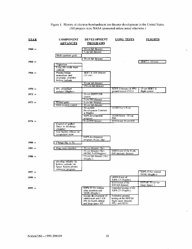
Figure 1 shows a "roadmap" of the history of
electron-bombardment ion thruster developmentin the United States from the first tests of a 10
cm engine 55 to the first operational flights in1997/1998. TM Much of the history of the early
development of mercury ion engines was outlined
in Reference 5. The following remarks only
focus on the insertion of component
improvements to the mercury and xenon ion
engines. In the early 1960s the wire-grids werereplaced by multiaperture grids, s6 Later, in the
mid-1960s engine life extension was made
possible by the incorporation of hollow cathodesfor the neutralizer and main discharge, sT-s9 The
SERT II flight was the major in-spacedemonstration of these technologies. 2_ Major
technology improvements in the 1970s were thedevelopment of high-perveance, dished grids 6_,
methods to control spalling of sputter deposited
NAS A/TM-- 1999-209439 7

materialin thedischargechamber41,andmethodsto providedeep-throttling.5 Mercuryenginesweredevelopedwithdiametersrangingfrom5cmto 150cm. Endurancetestsof theseenginesextendedfrom about 4,000 hours to15,000hours.
In the1980timeframeit wasdecidedto replacethemercuryengineswithxenonenginesbecausexenonwas lesscontaminatingto spacecraftsurfaces,andground-testoperationsweregreatlysimplified.In the 1980sand1990sring-cuspdischargechambers6_'62wereusedinsteadofdivergent-fieldchamberswhosepole-pieces,inthevicinityof thedischargechambercathode,sufferedsevereion erosion. The ring-cuspchambersdo not requirepole-piecesin thevicinityof thehollowcathode,andtheboundarymagneticfielddevicereducestheion lossestothe chamberwalls.6_ Additionally,long-life,xenonhollowcathodetechnologywasenhancedbydevelopmentsin theSpaceStationPlasmaContactorprogramwhichfocusedon definingreliableprocessing,handlingandtestproceduresforthecathodes)a Groundtestsof 13cmand30cmdiameterxenonenginesdemonstratedmorethan8,000hoursof reliableoperation,s4_'sThe
communication satellite and deep space tests of
these engines, starting in 1997, confirmed the
thrusters and PPUs are a very mature technology.
Overational Flights of Ion Provulsion
Systems
In 1997/1998, a new era of ion propulsion for
spacecraft began with the deployment ofcommunication satellites using an IPS with
0.44 kW thrusters tbr auxiliary propulsion and a
deep space mission using a 2.3 kW thruster.
These were the first operational uses of IPS by•United States industry and government.
PAS-5. _;alaxv Vlll-i. ASTRA-2A.
SATMEX 5. PAS B
As shown in Table 3, the Hughes Space and
Communications Company has launched five
operational communications satellites each
employing four-0.44 kW xenon ion thrusters forNSSK. s-'s_ The high specific impulse IPS
reduces the propellant requirements, versus
chemical systems, by 300 kg to 400 kg, thusallowing incorporation of more communications
hardware aboard the spacecraft or reduction inlaunch size and cost. The IPS consists of two
fully redundant strings each consisting of two
thrusters and one PPU. Two daily "burns" of
5 hours each are generally required for the NSSK
function. Typical spacecraft lifetime is about
15 years.
Approximate masses for a thruster and PPU are
5.0 kg and 6.8 kg, respectively. _ Overall IPS
dry mass for the spacecraft is about 68 kg. ThePPU contains seven power modules for the
beam, accelerator, discharge, two keepers
discharges, and two heaters. Overall PPU
efficiency of a BBPPU was 88%.
PanAmSat was Hughes' first customer for the
XIPS-13 propulsion system on PAS-5. This
was the first successful, operational spacecraft
employing IPS and was launched August 27,1997 from Kazakhstan on a Russian Proton
rocket. Since then, four more spacecraft are
operational using the XIPS-13 system namely,
Galaxy VllI-i, ASTRA-2A, SATMEX 5, andPAS 6B.
Deer Svace 1
The NSTAR program provided a single string,
primary IPS to the Deep Space I spacecraft. The
30 cm ion thruster operates over a 0.5 kW to
2.3 kW input power range providing thrust from
19 mN to 92 mN. The specific impulse rangesfrom 1900 s at 0.5 kW to 3100 s at 2.3 kW.
The flight thruster and PPU design requirementswere derived with .the aid of about 50
development tests and a series of wear-tests atNASA LeRC and JPL of 2000 hours, 1000
hours, and 8193 hours using engineering model
thrusters, 26s The flight-set masses for the
thruster. PPU, and DCIU were 8.2 kg, 14.77 kg,
and 2.51 kg, respectively 67. About 1.7 kg mass
was added to the PPU top plate to satisfy the
DSI micrometeoroid requirements. The powercable between the thruster and PPU was
comprised of two segments which were connected
at a field junction. The thruster cable mass was
0.95 kg, and the PPU cable mass was 0.77 kg.
The xenon storage and feed system dry mass was
about 20.5 kg. A total of 82 kg of xenon was
loaded for the flight. Thrusters and PPUs were
manufactured by Hughes, and the DCIU was
built by Spectrum Astro, Inc. The feed system
NASA/TM--1999-209439 8

developmentwasa collaborativeeffortbetweenJPLandMoog,Inc/'s
Asof April 27, 1999, the primary thrusting of
the NSTAR engine system required to encounter
the asteroid 1992KD was completed. The
thrusting time at the end of April was 1764hours. Thruster input power levels were varied
from 0.48 kWto 1.94 kW. Atotal of 11.6 kg
of xenon was expended. As shown in Table 4,
the NSTAR engine already has demonstrated the
largest propellant throughput in space as
compared to a SERT II engine that expended
about 9 kg of mercury. Propellant throughput is
a signature of total impulse capability. Nearly
70 kg of xenon remains on the DS 1 spacecraft
for a possible mission extension. It is intended
that the DS 1 spacecraft will pass within 10 km
of the asteroid 1992KD in July 1999. If an
extended mission is approved, DS 1 will
encounter comets Wilson-Harrington and Borrelty
in the year 2001.
Next G_neration Ion Propulsion
Z.t.thsl..el.q.xix_
Over the next decade, it is expected that there will
bc many communications spacecraft employing
the XIPS-13 and XIPS-25 propulsion systems.
Additionally, the Space Technology 4 spacecraft
will be developed by JPL for a flight to the
comet Tempel 1. and a small vehicle will be sentto the comet surface for scientific measurements.
The ST4 spacecraft will use three NSTAR ion
engine/PPU subsystems for primary propulsion.
In the next few years, new IPS technologies will
be developed by NASA for higher thrust density
30 cm ion engines and sub-kilowatt, smaller
engines both of which have application to
planetary and Earth-orbital spacecraft. Some of
the near-term work, shown in Figure 2, involves
development of titanium and carbon-carbon ion
optics which will provide significant lifetime
improvements compared to the baseline
molybdenum grid systems. Low-power and Iow-flowrate neutralizers are also needed tor a wide
class of thrusters which operate at low power
levels or are throttled over a wide range of input
power. Design approaches and manufacturing
technologies which provide reduced ion engine
and PPU mass and cost are receiving significantattention in order to enable or enhance planetary
and small-body missions using relatively smalllaunch vehicles.
Conclusions
The historical background and characteristics of
the experimental flights of ion propulsion
systems and the major ground-based technologydemonstrations were reviewed. The results of the
first successful ion engine flight in 1964. SERTI which demonstrated ion beam neutralization, are
discussed along with the extended operation of
SERT II starting in 1970. These results together
with the technology employed on the early
cesium engine flights, the ATS series, and the
ground-test demonstrations, have provided the
evolutionary path for the development of xenon
ion thruster component technologies, control
systems, and power circuit implementations. In
the 1997-1999 period, the communication
satellite flights using ion engine systems and the
Deep Space 1 flight confirmed that these
auxiliary and primary propulsion systems have
advanced to a high-level of flight-readiness.
References
1. Beattie, J. R., Williams, J. D., and Robson,
R. R., "Flight Qualification of an 18-raN Xenon
lon Thruster," IEPC Paper 93-106, September1993.
2. Sovey, J. S. et al., "Development of an IonThruster and Power Processor for New
Millennium's Deep Space 1 Mission," AIAA
Paper 97-2778, July 1997.
3. Cybulski, R. J., et al., "Results from SERT I
Ion Rocket Flight Test," NASA TN D-2818,March 1965.
4. Anon., "Ion Propulsion, Over 50 Years in
the Making,"http://science.nasa.gov/newhome/headlines/ion-ast.htm. February 1999.
5. Anon., "A Case History of Technology
Transfer." NASA TM-82618. August 1981.
6. Holcomb, L. B., "Survey of Satellite
Auxiliary Electric Propulsion Systems," Journal
of Spacecraft and Rockets. Vol. 9, No. 3, March1972.
NASA/TM--1999-209439 9

7. Molitor, J. H., "Ion PropulsionFlightExperience,Life Tests, and Reliability
Estimates," Journal of Spacecraft and Rockets,
Vol. II, No. 10, October 1974.
8. Pollard, J. E., et al., "Electric Propulsion
Flight Experience and Technology Readiness,"
AIAA Paper 93-2221, June 1993.
9. Maninez-Sanchez, M. and Pollard, J. E.,
"Spacecraft Electric Propulsion-An Overview,"
Journal of Propulsion and Power, Vol. 14,
No. 5, September-October 1998.
10. Davis, J., "Sub-orbital Flight Testing of
Electric Propulsion Systems," proceedings of the
Symposium of Advanced Propulsion Concepts.
Science Publishers, Inc., January 1966,
pp. 1-20.
11. Tannen. P. D., "Engineering Support Ior
Electric Propulsion Space Tests," in AFSC llth
Annual Air" Force Science atut Engineering
Symposium, June 1964,
12. Ernstene. M. P., et al., "Surface Ionization
Engine Development." Journal of Spacecraft and
Rockets, Vol. 3. No. 5, May 1966,
pp. 744-747.
13. Gold, H., et al., "Description and Operation
of Spacecraft in SERT I Ion Thruster FlightTest," NASA TMX- 1077, March 1965.
14. Tannen, P. D. and Radoy, C. H., "Electric
Propulsion Space Tests," USAF Technical
Report Number AFSWC TR-65-2, June 1965.
15. Brunings, J. E. and Johnson, C. E.,
"Nuclear Power in Space," Mechanical Engin-
eering, February 1967, pp. 35-41.
16. Davis, J. D. and Burnett. J. R., "Radiation
Hardening of an Ion Propulsion System," in
Record of the 1965 htternational Symposium on
Space Electronics. November 1965, pp. 13-B1to 13-B 16.
17. Sellen. J. M., "Interaction of Spacecraft
Science and Engineering Subsystems with
Electric Propulsion Systems," AIAA Paper69- I i06, October 1969.
18. Hunter, R. E., et al., " Cesium Contact Ion
Microthruster Experiment aboard Applications
Technology Satellite (ATS)-IV," Journal of
Spacecraft and Rockets, Vol. 6, No. 9,
September 1969, pp. 968-970.
19. Worlock, R., et al., "An Advanced Contact
Ion Microthruster System," Journal of Spacecraft
and Rockets, Vol. 6, No. 4, April 1969,
pp. 424-429.
20. James, E. L. and i3oldner, S. J., "Ion Engine
Systems Testing," AFAPL-TR-69112, February1970.
21. Bartlett, R. O., et al., "Spacecraft Charging
Control Demonstration at Geosynchronous
Altitude," AIAA Paper 75-359, March 1975.
22. Olsen, R. C., "Experiments in Charge
Control at Geosynchronous Orbit--ATS-5 and
ATS-6," Journal of Spacecraft and Rockets
Vol. 22, No. 3, May-June 1985.
23. Kerslake, W. R. and Ignaczak, L. R.,
"Development and Flight History of SERT 1I
Spacecraft," AIAA Paper 92-3516. July 1992.
24. James, E. L., et al., "A North-South
Stationkeeping Ion Thruster System for
ATS-F," AIAA Paper 73-I133, October 1973.
25. Worlock, R. M., et al., "The Cesium
Bombardment Engine North-South Station-
keeping Experiment on ATS-6," AIAA Paper75-363, March 1975.
26. Masek, T. D. and Cohen, H. A., "Satellite
Positive-lon-Beam System," Journal of Space-
craft and Rockets, Vol. 15, No. I.
January-February 1978, pp. 27-33.
27. Olsen, O. C., "Investigation of Beam-
Plasma Interactions," Final Report, NASA
CR-180579, May 1987.
28. Shuman, B. M. and Cohen, H. A.,
"Automatic Charge Control System torSatellites," NASA Conference Publication 2359,
also AFGL-TR-85-O018, papers from the
Spacecraft Environmental Interactions
Technology Conference held in October 1983.
NASA/TM--1999-209439 10

29.Masek,T. D. andPawlik,E. V., "ThrustSystem Technologylbr Solar ElectricPropulsion,"AIAAPaper68-541,June1968.
30.Macie,T.W.,etal.,"Integrationof aFlightPrototypePowerConditionerwitha 20-cmIonThruster,"AIAAPaper71-159,January1971.
31.Hyman,J., "DesignandDevelopmentof aSmall StructurallyIntegratedton ThrusterSystem,"NASACR-120821,October1971.
32.Hyman,J., "Pertormance Optimized, Small
Structurally Integrated Ion Thruster System,"NASA CR-121183, May 1973.
33. Nakanishi, S., et al.. "Status of a Five-
Centimeter-Diameter Ion Thruster Technology
Program," AIAA Paper 71-690, June 1971.
34. Nakanishi, S., "Durability Tests of s Five-
Centimeter Ion Thruster System," AIAA Paper72-1151, November 1972.
35. Nakanishi, S. and Finke, R. C., "A
9700-Hour Durability Test of a Five Centimeter
Diameter Ion Thruster," AIAA Paper 73-1111,November 1973.
36. Duxbury, J. H., "A Solar-Electric Spacecraft
for the Encke Slow Flyby Mission," ALAA
Paper 73-1126, November 1973.
37. Anon., "30-Centimeter Ion Thrust
Subsystem Design Manual," NASA TM-7919 I,June 1979.
38. Sharp, G. R., "Thruster Subsystem Moduletor Solar Electric Propulsion." Journal of
Spacecraft and Rockets, Vol. 13, No. 2. February
1976, pp. 106-110.
39. Schnelker, D. E. and Collett. C. R., "30-cm
Engineering Model Thruster Design andQualification Tests," AIAA Paper 75-341,March 1975.
40. Collett, C. R., et al.. "Thruster Endurance
Test," NASA CR-135011, May 1976.
41. Power, J. L. and Hiznay, D. J., "Solutions
for Discharge Chamber Sputtering and Anode
Deposit Spalling in Small Mercury Ion
Thrusters," AIAA Paper 75-399, March 1975.
42. Bechtel, R. T., et al., "Results of the
Mission Profile Life Test," AIAA Paper82-1905, November 1982.
43. Rawlin, V. K. and Mantenieks, M. A.,
"Effect of Facility Background Gases on InternalErosion of the 30-cm HG Ion Thruster," AIAA
Paper 78-665, April 1978.
44. Bless, J. J., et al., "Electric Prototype PowerProcessor for a 30 cm Ion Thruster," NASA
CR-135287, March 1977.
45. Power. J. L., "Planned Flight Test of a
Mercury Ion Auxiliary Propulsion
System--Objectives, System Descriptions, and
Mission Operations," AIAA Paper 78-647, April1978.
46. Collett. C. R., "Auxiliary Propulsion
System Flight Package," NASA CR-180828,November 1987.
47. Smith, B. A., "Teal Ruby Spacecraft to be
Put in Storage at Norton AFB," Aviation Week
& Space Technology, January 8, 1990,
pp. 22-23.
48. Nakanishi, S., "A 15,000-Hour CyclicEndurance Test of an 8-Centimeter-Diameter
Electron Bombardment Mercury Ion Thruster,"NASA TMX-73508, November 1976.
49. Dulgeroff, C. R., et al., "lAPS (8-cm) Ion
Thruster Cyclic Endurance Test," IEPC Paper
84-37, May 1984.
50. Francisco, D. R.. et al., "Successful
Completion of a Cyclic Ground Test of a
Mercury Ion Auxiliary Propulsion System,"
IEPC Paper 88-035, October 1988.
51. Beattie, J. R., et al., "Status of Xenon Ion
Propulsion Technology," A1AA Paper 87-1003,
May 1987.
NASA/TM-- 1999-209439 11

52.Beattie,J. R., "XIPSKeepsSatellitesonTrack,"The Industrial Physicist, June 1998,
pp. 24-26.
53. Anon., "Power to Burn: Versatile New
Series Answers Customer Needs,"
http://www.hughespace.com/factsheets/702/702.html.
54. Anon.. "XIPS: The Latest Thrust in
Propulsion Technology,"http://www.hughespace.com/factsheets/xi
ps/xips.html.
55. Kaufman, H. R., "An Ion Rocket with an
Electron-Bombardment Ion Source," NASA TN
D-585, 1961.
56. Kaufman, H. R. and Reader, P. D.,
"Experimental Performance of Ion Rockets
Employing Electron-Bombardment Ion Sources,"
in Progress in Astronautics and Rocketry,
Voi. 5, Electrostatic Propulsion, Academic
Press. Inc., 1961, pp. 3-20.
57. Sellen, J. M. and Kemp, R. F., "Research
on Ion Beam Diagnostics." NASA CR-54692,1966.
58. Sohl, G., Fosnight, V. V., and Goldner, S.
J., "Electron Bombardment Cesium lon Engine
System." NASA CR-5471 I, April 1967.
59. Rawlin, V. K. and Pawlik, E. V., "A
Mercury Plasma-Bridge Neutralizer," Journal of
Spacecraft and Rockets, Vol. 5, February, 1968,
pp. 159-164.
60. Rawlin, V. K., Banks, B. A., and Byers, D.
C., "Design, Fabrication, and Operation ofDished Accelerator Grids on a 30 cm Ion
Thruster." AIAA Paper 72--486, 1972.
61. Moore, R. D., "Magneto-Electrostatically
Contained Plasma Ion Thruster," AIAA Paper69-260, March 1969.
62. Sovey, J. S., "Improved Ion Containment
Using a Ring-Cusp Ion Thruster," Journal of
Spacecraft and Rockets, Vol. 21, No. 5,
September-October 1984, pp. 488-495.
63. Matossian, J. N. and Beattie, J. R.,
"Characteristics of Ring-Cusp Discharge
Chambers," Journal of Propulsion and Power,
Vol. 7, No. 6, November-December 1991,
pp. 968-974.
64. Patterson, M. J., et al., "Plasma Contactor
Technology for Space Station Freedom," AIAA
Paper 93-2228, June 1993.
65. Polk, J. E., et al., "The Effect of EngineWear on Performance in the NSTAR 8000 Hour
Ion Engine Endurance Test," AIAA Paper
97-3387, July 1997.
66. Beattie, J. R., Williams, J. D., and Robson,
R. R., "Flight Qualification of an 18-mN Xenon
Ion Thruster," IEPC Paper 93-106, September1993.
67. Gronroos, H. G., NSTAR Project Office at
JPL, Private Communication, May 1998.
68. Bushway, E. D., Engelbrecht. C. S.. "and
Ganapathi, G. B., "NSTAR Ion Engine Xenon
Feed System: Introduction to System Design and
Development," IEPC Paper 97-044. August.1997.
NASA/TM--1999-209439 12

Table la. Experimental Flights of Ion Propulsion Systems
Spacecraft Program SERT I Program 661A, Program SNAPSHOT
661A, Test Test Code B 661A, TestCode A Code C
S p o n s o r USAF NASA LeRC USAF USAF USAF
Builder of IPS EOS LeRC HuLzhes EOS EOS EOS
Launch date 12.18.62 07.20.64 08.29.64 12.21.64 04.03.65
Orbit, km Suborbital Suborbital Suborbital Suborbital
IPS type Contact Contact Contact
ionization ionization ionization
Pro p ella n t Cesium Cesium Cesium
No. of thrusters 1
Thruster anode -7 cm
diameter
Type of Wire filament
neutralizer
5000 VBeam power
supply voltage
Power per 0.77 kWthruster
Maximum thrust 8.9 mN
Specific impulse 7400 s
Propellant mass
Maximum in-
space operationtime for one
thruster
Longest groundtest
Comment
2_
0 min.
1230 h
HV powersupply taileddue tocontaminationtiom gasesvented frombatteries. Ref.10
Electron Contact
bombard- ioniza-
ment lion
Mercury Cesium
1 1
10 cm 8 cm
Ta wire Ta wire
2500 V 4500 V
1.4 kW 0.6 kW
28 mN 5.6 mN
4900 s 8050 s
31 min. 0 min.
1PS and Cesiumneutraliza- engine hadlion a HVdemonstra- short..lion. Ref. 3 Ref. 3
1 1
-7 cm -7 cm
Wire filament Wire filament
in beam
5000 V 5000 V
700
Contact
ionization
Cesium
1
-5 cm
Wire
filament.
barium
coated
4500 V
0.77 kW 0.77 kW -(I.4 kW
8.9 mN 8.9 mN
7400 s 7400 s
-19 min. -4 min.
Failed 3rd stageburn shortened
operation,Obtained -20% offull thrust..Ref. 14
Stable operation of theIPS. S/C potential-1000 V at full thrust..Ref. 14
-8.5 mN
5100 s
<60 min.
Continuousarcing at HVterminalsinduced EMIto the S/C
systems.
Ref. 16
NASAlTM--1999-209439 13

Tablelb. ExperimentalFlightsof IonPropulsionSystems
Spacecraft
Sponsor
Builder of IPS
Launch date
ATS-4 ATS-5
Orbitr km
IPS type
Propellant
No. of thrusters
Thruster anode
diameter
Type ofneutralizer
Beam power
supply voltage
Power perthruster
Maximum thrust
SERT II ATS-6 SCATHA
P78-2
USAF/NASA USAF/NASA NASA LeRC NASA GSFC USAF/NASA
GSFC GSFC GSFC
EOS EOS EOS
08.12,69
36,000
Contact
ionization
08.10.68
218x760
Contact
ionization
Cesium Cesium
2 2
5cm5 cm
Ta doped with
Yttrium
Ta doped with
Yttrium
3000 V 3000 V
0.02 kW 0.02 kW
0.089 mN 0.089 mN
Specific impulse 6700 s 6700 s
-0.05 k EPropellant mass
Max. in-space -10 h No operation
operation time withaHV
for one thruster beam.
Longest ground 2245 h
test_s)
Comment
NASA LeRC,
Westin[house
02.03.70
1000
05.30.74
36,000
Hughes
(ion source)
01.30.79
43,000x27,000
S/C was in a lowaltitude parkingorbit due to aCentaur stagefailure. Firstsuccessfullorbital test of anion engine. NoEMI to S/Csubsystems.Ref. 18
Electron Electron Electron
bombardment bombardment bombardment
Mercury Cesium Xenon
2 2 1
15 cm 8 cm 3.6 cm
Hollow Cesiated Ta Ta doped with
cathode Yttrium
3000 V 56O V
0.15 kW
1000 V to
2OO0 V
0.03 to 0.045
kW
4.5 mN 0.14 mN
2500 s 350 s
3.6 k_ 0.3 k_
92 h
-600 h
S/C had a 76RPM spin=rate.This produced a4g field whichcompromised thecesium feed
system andprecludednormaloperation.Ref. 21
0.85 kW
28 mN
4200 s
15 k_
-3781 h
6742 h,
5169 h
One ion engineoperated 3781 huntil theneutralizer tank
was depleted.The other enginehad a grid shortwhich limited
operation to2011 h. Ref. 23
2614 h,
471 c_/cles
One thruster
operated for ~1hour and theother for 92hours. Furtherthrusting wasterminated due to
a feed system"flooding"problem. NoEMI. Ref. 24
Operations wereperformedintermittantlyover a 247 dayperiod. Ref. 26
NASA/TM-- 1999-209439 14
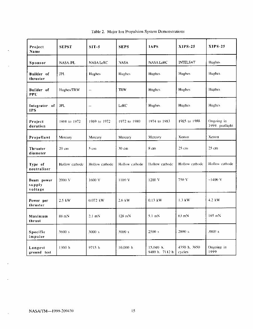
Table2. MaiorIonPropulsionSystemDemonstrations
Project SIT-5Name
Sponsor NASA LeRC
Builder of Hughes
thruster
Builder of
PPU
IntegratorIPS
Project 1969 to 1972
duration
Propellant Mercury
Thruater 5 cm
diameter
Hollow cathodeType ofneutralizer
Beam power
supply
voltage
Power perthruster
Maximum
thrust
Specific
impulse
Longest
ground test
SEPST
NASA JPL
JPL
Hughes/TRW
of JPL
1968 to 1972
Mercury
20 cm
Hollow cathode
2000 V
2.5 kW
88 mN
1600 V
0.072 kW
SEPS
NASA
Hughes
TRW
LeRC
1972 to 1980
Mercury
30 cm
Hollow cathode
I100 V
lAPS
NASA LeRC
Hughes
Hughes
Hughes
1974 to 1983
Mercury
8 cm
Hollow cathode
1200 V
XIPS-25
INTELSAT
Hughes
Hughes
Hughes
1985 to 1988
Xenon
25 cm
Hollow cathode
750 V
XIPS-25
Hughes
Hughes
Hughes
Hughes
Ongoing in
1999. preflight
Xenon
25 cm
Hollow cathode
1400 V
3600 s
1300 h
2.1 mN
3000 s
2.6 kW
128 mN
3000 s
0.13 kW
5.1 mN
2500 s
1.3 kW
63 mN
2800 s
4.2 kW
165 mN
3800 s
9715 h 10,000 h 15,040 h,
9489 h, 7112 h
4350 h, 3850
cycles
Ongoing in1999
NASA/TM--1999-209439 15

Table3. OperationalFlightsofIonPropulsionSystems
PAS-5 Galaxy ASTRA- Deep SATMEX PAS 6B
Spacecraft VlII-i 2A Space 1 5
Sponsor PanAmSat PanAmSat SES NASA Satmex PanAmSatLeRC/JPL
i
Builder of IPS Hu_hes Hu_hes Hu_hes Hu£hes Hu_hes Hu_hes
Launch date 08.27.97 12.08.97 08.29.98 10.24.98 12.05.98 12.21.98
Orbit, km 36.000 36,000 36,000 Orbits sun 36,000 36,000
IPS type Electron Electron Electron Electron Electron Electronbombardm't bombardm't bombardm't bombardm't bombardm't bombardm't
Xenon Xenon Xenon Xenon Xenon XenonPropellant
No. of thrusters 4 4 4 1 4 4
Thruster diameter 13cm 13cm 13cm 30cm 13cm 13cm
Type of Hollow Hollow Hollow Hollow Hollow Hollowneutralize r cathode cathode cathode cathode cathode cathode
Beam power 750 V 750 V 750 V 650 V to 750 V 750 V
supply volta[[e 1100 V
0.44 kW 0.44 kW 0.44 kW 0.44 kW 0.44 kWPower perthruster
0.50 kW to
2.3 kW
Maximum thrust 18mN 18mN 18raN 92raN 18mN 18mN
Specific impulse 2590 s 2590 s 2590 s 1900 s to 2590 s 2590 s
3100 s
Propellant mass >100 kg >100 kg >100 kg 82 kg >100 kg >100 kg
Maximum in- 1764 h as of
space operation 04.27.99
time for one
thruster
Longest ground >8000 h 8193 h
test
NASA/TM-- 1999-209439 16

Table 4. Comparison of the Propellant Throughput Capability of the
SERT II and Deep Space I Ion Propulsion Systems
SERT II
Propellant type
_on_est ,ground test
Maximum thruster propellant throughput in-space
NSTAR/Dee 9 Snace 1
Propellant type
.onE.est ground test
Maximum thruster propellant throughput in-spaceas of 04.27.99
DS I propellant throughput capability for the
primary and extended mission
Propellant Throughput
Me_u_
-16 k_
Estimated to be -9 kg
Xenon
87.5 k_
I 1.6 kg
82 kg
NAS A/TM-- 1999-209439 17
FigureI. Historyofelectron-bombardmentionthrusterdevelopmentintheUnitedStates.(All projectswereNASAsponsoredunlessnotedotherwise.)
YEAR
1960 ->
1964 ->
1966 ->
1970 ->
1972 ->
1973->
1976->
1980 ->
1981->
1988->
1997 ->
1998 ->
1999 ->
COMPONENT DEVELOPMENT _
ADVANCES PROGRAMS
I Multi-aperture grids
VaporizerLong-life oxide main
cathodePlasma bridgeneutralizer anddischarge chamber
hollow cathode
I HV, propellantisolator { Hu_hes)
I Dished [zrids
Grid erosion control
Control of spalledflakes in dischargechamber
Test facility effects on
component wear
I Chan_e H_ -> Xe
I Rin_.-cusp chamber
Develop reliable Xehollow cathode via
Space Station plasma
contactor program
10-cm lab thruster I
I5-cm lab thruster
20-cm lab thruster ]
SERT II EM thruster
(15-cm)
50-cm lab thruster
150-cm lab thruster
20-cm SEPST EM
s_'stem5-cm EM thruster
8-cm lab thruster
30-cm lab thruster
30 cm EM
Development Contract
at Hu_hes
SEPS development
pro[zram8-cm EM thruster
lAPS development
program (8-cm, H_)
30-cm thruster (Xe)
25-cm thruster (Xel
([NTELSAT/Hu_hes)13-cm lab thruster (Xe)
(Hu_hes)
] SERTI (10-cm)
SERT II thruster& PPU I 15-cm SERT 11
_,ound-tested 6742 h I flight svstem
15,_ h test-8 cm
I 0,000 h test - 30 emEM
5070 h test-30 cm EM
XIPS-25 for comsatorbit insertion and
NSSK (Hu_hes)Initiate development ofsubkilowatt and 5 kWIPS for Earth-orbital
and deep space S/C
9489 h test of the 8-cm. I
EM mercury thruster I
>8000 h test of
XIPS-13 (Hu_hes)8193 h test of theNSTAR thruster
Extended testing of theXIPS-25 (Hughes)
XIPS- 13 for comsat
NSSK (Hu_hcs)
NSTAR 30-cm lor
Deep Space 1
Extended ground-testing of the NSTARflight spare thruster,PPU, and DCIU
NASA_M I 1999-209439 18

Figure 2. Ion propulsion technology roadmap for Earth-orbital and planetary applications
(Calendar Year)
1995
Hughes PAS-5,500 W XIPS
(First of many S/C)
2000 2005 2010
t t 0Hughes 701S/C4.2 kWXIPS
INSTAR on. I
[Deep Space I,2.5 kW |PS
Flight Applications
Space Technology 4,3 NSTAR
subsystem IPS
2 X CostReduction
in IPS
1Taurus Planetary mission, 1
Europa Orbiter, Outer Planet Explorer_li_i_
High Delta-V Orbit Transfers, _"
DoD Missions /
t
2.5 kW IPS
Core Technology
5 kW 1PS High Power IPSI Low Power IPS
J
Cathode Low Flow
Technologies Neutralizer
1Titanium Carbon- Sub-Kilowatt Sub 100 _' 10 kW- 30 k_'
Ion Optics Carbon Thruster Thruster Systems Fion Optics (Efficiency) (low mass)
NASAfYM--1999-209439 19

REPORT DOCUMENTATION PAGE Fo_ApprovedOMB No. 0704-0188
Public reporting burden for this collection of information is estimated to average 1 hour per response, including the lime for reviewing instructions, searching existing data sources.
gathering and maintaining the data needed, and completing and reviewing the collection of information. Send comments regarding this burden estimate or any other aspect of this
collection of information, including suggestions for reducing this burden, Io Washinglon Headquarters Services, Directorate for information Operations and Reports, 1215 Jefferson
Davis Highway, Suite 1204. Arlington, VA 22202-4302, and to the Office of Management and Budget, Paperwork Reduction Project (0704-0188), Washington, DC 20503
1. AGENCY USE ONLY (Leave blank) 2. REPORT DATE 3. REPORT TYPE AND DATES COVEREDOctober 1999 Technical Memorandum
4. TITLE AND SUBTITLE
A Synopsis of lon Propulsion Development Projects in the United States:
SERT I to Deep Space I
6. AUTHOR(S)
James S. Sovey, Vincent K. Rawlin, and Michael J. Patterson
7. PERFORMING ORGANIZATION NAME(S) AND ADDRESS(ES)
National Aeronautics and Space Administration
John H. Glenn Research Center at Lewis Field
Cleveland, Ohio 44135-3191
9. SPONSORING/MONITORING AGENCY NAME(S) AND ADDRESS(ES)
National Aeronautics and Space Administration
Washington, DC 20546-0001
5. FUNDING NUMBERS
WU-632-1B-I B-00
8. PERFORMING ORGANIZATION
REPORT NUMBER
E-11916
10. SPONSORING/MONITORINGAGENCY REPORTNUMBER
NASA TM-- 1999-209439
AIAA 99-2270
11. SUPPLEMENTARY NOTES
Prepared for the 35th Joint Propulsion Conference and Exhibit cosponsored by the AIAA, ASME, SAE. and ASEE
Los Angeles, California, June 20-24, 1999. Responsible person, James S. Sovey, organization code 5430,
(216) 977-7454.
12a. DISTRIBUTION/AVAILABILITY STATEMENT
Unclassified - Unlimited
Subject Category: 20 Distribution: Nonstandard
This publication is available from the NASA Center for AeroSpace Information. (301) 621-0390.
12b. DISTRIBUTION CODE
13. ABSTRACT (Maximum 200 words)
The historical background and characteristics of the experimental flights of ion propulsion systems and the major ground-
based technology demonstrations were reviewed. The results of the first successful ion engine flight in 1964, SERT I which
demonstrated ion beam neutralization, are discussed along with the extended operation of SERT II starting in 1970. These
results together with the technology employed on the early cesium engine flights, the ATS series, and the ground-test
demonstrations, have provided the evolutionary path for the development of xenon ion thruster component technologies,
control systems, and power circuit implementations. In the 1997-1999 period, the communication satellite flights using ion
engine systems and the Deep Space 1 flight confirmed that these auxiliary and primary propulsion systems have advanced
to a high-level of flight-readiness.
14. SUBJECT TERMS
Propulsion; Electric propulsion; Spacecraft propulsion; Plasma applications
17. SECURITY CLASSIFICATIONOF REPORT
Unclassified
NSN 7540-01-280-5500
18. SECURITY CLASSIFICATIONOF THIS PAGE
Unclassified
19. SECURITY CLASSIFICATIONOF ABSTRACT
Unclassified
15. NUMBER OF PAGES
2516. PRICE CODE
A03
20. LIMITATION OF ABSTRACT
Standard Form 298 (Rev. 2-89)Prescribed by ANSi Std. Z39-1 8
298-102