A Swimming Robot Actuated by Living Muscle Tissue
10
A Swimming Robot Actuated by Living Muscle Tissue Citation Herr, Hugh, and Robert G Dennis. 2004. A swimming robot actuated by living muscle tissue. Journal of NeuroEngineering and Rehabilitation 1: 6. Published Version doi:10.1186/1743-0003-1-6 Permanent link http://nrs.harvard.edu/urn-3:HUL.InstRepos:4740799 Terms of Use This article was downloaded from Harvard University’s DASH repository, and is made available under the terms and conditions applicable to Other Posted Material, as set forth at http:// nrs.harvard.edu/urn-3:HUL.InstRepos:dash.current.terms-of-use#LAA Share Your Story The Harvard community has made this article openly available. Please share how this access benefits you. Submit a story . Accessibility
Transcript of A Swimming Robot Actuated by Living Muscle Tissue
A Swimming Robot Actuated by Living Muscle Tissue
CitationHerr, Hugh, and Robert G Dennis. 2004. A swimming robot actuated by living muscle tissue. Journal of NeuroEngineering and Rehabilitation 1: 6.
Published Versiondoi:10.1186/1743-0003-1-6
Permanent linkhttp://nrs.harvard.edu/urn-3:HUL.InstRepos:4740799
Terms of UseThis article was downloaded from Harvard University’s DASH repository, and is made available under the terms and conditions applicable to Other Posted Material, as set forth at http://nrs.harvard.edu/urn-3:HUL.InstRepos:dash.current.terms-of-use#LAA
Share Your StoryThe Harvard community has made this article openly available.Please share how this access benefits you. Submit a story .
Accessibility
BioMed Central
Journal of NeuroEngineering and Rehabilitation
ss
Open AcceResearchA swimming robot actuated by living muscle tissueHugh Herr*1 and Robert G Dennis2Address: 1Media Laboratory and the Harvard-MIT Division of Health Sciences and Technology, Massachusetts Institute of Technology, Cambridge, MA 02139, USA and 2Department of Biomedical Engineering, University of North Carolina at Chapel Hill, NC 27599, USA
Email: Hugh Herr* - [email protected]; Robert G Dennis - [email protected]
* Corresponding author
Biomechatronicsbionicscyberneticshybrid roboticsmuscle actuatorsskeletal musclemuscle organ culturefunctional electrical stimulation
AbstractBiomechatronics is the integration of biological components with artificial devices, in which thebiological component confers a significant functional capability to the system, and the artificialcomponent provides specific cellular and tissue interfaces that promote the maintenance andfunctional adaptation of the biological component. Based upon functional performance, muscle ispotentially an excellent mechanical actuator, but the larger challenge of developing muscle-actuated, biomechatronic devices poses many scientific and engineering challenges. As ademonstratory proof of concept, we designed, built, and characterized a swimming robot actuatedby two explanted frog semitendinosus muscles and controlled by an embedded microcontroller.Using open loop stimulation protocols, the robot performed basic swimming maneuvers such asstarting, stopping, turning (turning radius ~400 mm) and straight-line swimming (max speed >1/3body lengths/second). A broad spectrum antibiotic/antimycotic ringer solution surrounded themuscle actuators for long term maintenance, ex vivo. The robot swam for a total of 4 hours overa 42 hour lifespan (10% duty cycle) before its velocity degraded below 75% of its maximum. Thedevelopment of functional biomechatronic prototypes with integrated musculoskeletal tissues isthe first critical step toward the long term objective of controllable, adaptive and robustbiomechatronic robots and prostheses.
BackgroundMany technological barriers exist for the implementationof life-like mobility in robotic and prosthetic systems.Included among these barriers are (1) the availability ofhigh-energy density storage media, (2) the availability ofadequate muscle-like actuators, and (3) the availability ofbiologically inspired sensory technologies. As a possibleresolution to these challenges, we consider in this investi-gation the use of living muscle tissue as a viable actuatorfor synthetic devices.
Although important research has been conducted toadvance a synthetic actuator technology with muscle-likeproperties, engineering science has not yet produced amotor system that can mimic the contractility, energetics,scalability and plasticity of living muscle tissue [1,2]. Mus-cle has several important advantages in addition to favo-rable dynamic characteristics [1-6]. In its function as amotor, muscle acts to provide positive mechanical work ata considerable aerobic transduction efficiency, or 1000Joules of work per gram of glucose consumed [7]. It is a"smart material", having integrated sensors for the
Published: 28 October 2004
Journal of NeuroEngineering and Rehabilitation 2004, 1:6 doi:10.1186/1743-0003-1-6
Received: 10 September 2004Accepted: 28 October 2004
This article is available from: http://www.jneuroengrehab.com/content/1/1/6
© 2004 Herr and Dennis; licensee BioMed Central Ltd. This is an Open Access article distributed under the terms of the Creative Commons Attribution License (http://creativecommons.org/licenses/by/2.0), which permits unrestricted use, distribution, and reproduction in any medium, provided the original work is properly cited.
Page 1 of 9(page number not for citation purposes)
Journal of NeuroEngineering and Rehabilitation 2004, 1:6 http://www.jneuroengrehab.com/content/1/1/6
detection of displacement and rate of displacement (mus-cle spindles) as well as force (Golgi tendon organs). It canrepair itself when damaged, and can functionally adapt toan increase in the demands of the environment by under-going hypertrophic and hyperplastic growth [8] as well asfiber type transformations [9-12]. Muscle has integratedseries-elastic components, which are thought to give riseto many of the "life-like" characteristics of animal move-ment [13], and the fuel that it consumes is a renewableresource, while the waste products produced are environ-mentally compatible.
In this investigation, we examine the feasibility of usinganimal-derived muscle as an actuator for artificial devicesin the millimeter to centimeter size scale. Perhapsresearchers in the past did not consider muscle tissue aviable mechanical actuator because of tissue maintenanceand control difficulties. The objectives of this study are toidentify, and to begin to address, the many technical chal-lenges related to maintaining and controlling explantedmuscle tissues in the context of a robotic platform. To thisend, we construct a hybrid swimming robot comprising asynthetic elastomeric tail actuated by a single pair ofwhole muscle explants from frog semitendinosus muscle.We anticipate that basic swimming maneuvers such asstraight-line swimming and turning can be performed byalternately modulating electrical signals to each muscleactuator across two electrode pairs, one on each musclenear the neuromotor junction. We further anticipate thata multi-day robotic maintenance or lifespan can beachieved by surrounding the muscle actuators with a spe-cific bath of amphibian ringer's solution comprising anti-biotic and antimycotic agents. To test these ideas, weconstruct two robotic build-ups, each comprising a freshlydissected pair of explanted semitendinosus muscles. Foreach build-up, pilot data are collected to characterize therobot's swimming mechanics and lifespan.
MethodsMuscle Removal and MaintenanceThe surgical removal of muscle specimens designated forrobotic actuation were performed according to procedures
approved by the Committee on Animal Care, Northeast-ern University (Approval #0402-025-05). Briefly, adultfrogs (Rana pipiens) were pithed, and both semitendino-sus muscles were dissected free and removed with tendonsintact. Before removal of the tissues from the animal, thelength of each muscle belly was measured at an equilib-rium or rest length. The resting length measurement wasconducted on the intact muscle specimen with the limbpositioned at an anatomically neutral position (see Table1 for muscle lengths). After removal from the animal, themuscle, including its intact tendons, was weighed (seeTable 1 for muscle mass). Each tendon was manipulatedvia tightly secured silk suture (size 5-0). Each muscle wasthen pinned at its rest length in a 100 mm Petri dish witha previously prepared SYLGARD (Dow Chemical) poly-dimethylsiloxane (PDMS) substrate.
Shortly before harvesting the muscles, two fresh liters ofamphibian ringer solution were prepared according to aprotocol specifically designed for frog organ culture[14,15]. The amphibian ringer comprised: NaCl, 83.89mM; NaHCO3, 28.11 mM; KCL, 1.5 mM; KH2PO4, 1.2mM; MgSO4, 1.2 mM; CaCl2 Dihydrate, 1.3 mM; Glucose,10 mM; MEM Amino Acid Mixture, 1:50 dilution (GIBCO#1130051); MEM Vitamin Mixture, 1:100 dilution(GIBCO # 1120052); Creatine, 1 mM; DL-Carnitine, 1mM; Ferric Chloride, 0.9 µM; Human Serum Transferrin,1.35 µM; Insulin, 1 mU/ml; L-Glutamine, 1:100 dilution;Sigma Chemical #A9909, 1:50 dilution (an antibiotic/antimycotic). A broad-spectrum, antibiotic/antimycoticwas added out of necessity for long-term maintenance ofthe muscles, ex vivo. We observed, for periods greater than24 hours, septic degradation of the muscle specimens inthe absence of the antibiotic/antimycotic agents. Aftereach muscle was placed within a Petri dish, a small vol-ume of ringer solution was used to surround each muscle,the balance being used in the test tank for the swimmingrobot evaluations. The total amount of time betweenmuscle removal from the animal to finalizing the muscleinstallation into the robotic swimmer was approximately1 hour.
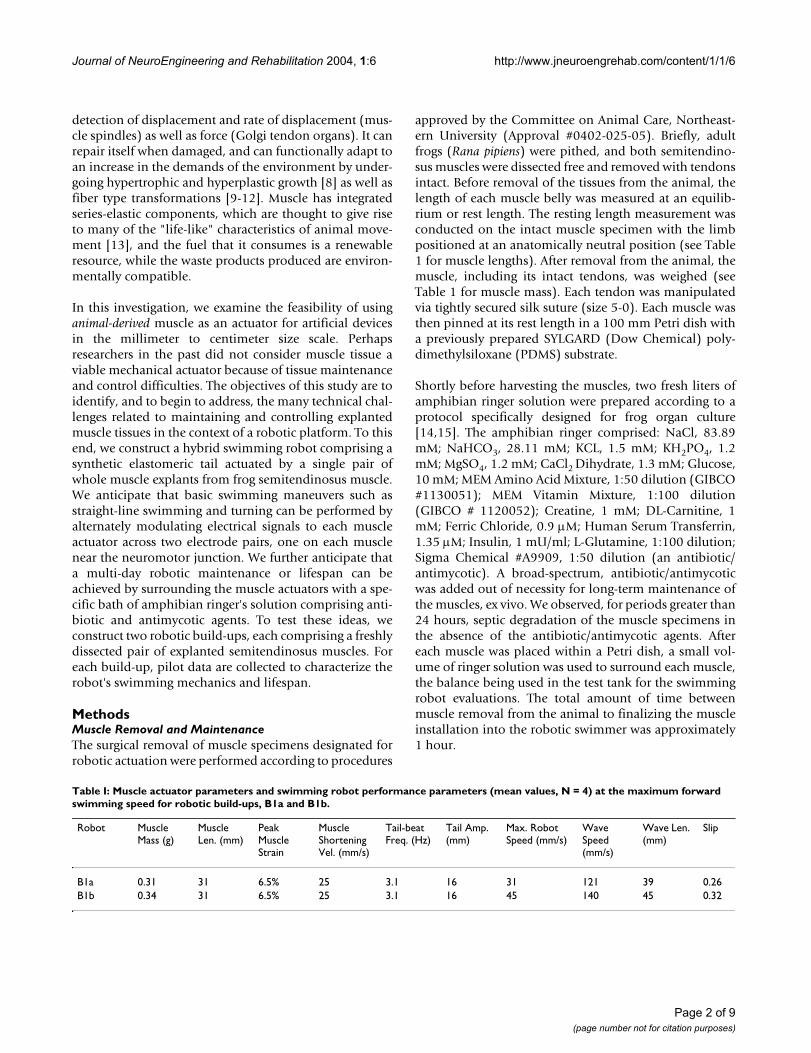
Table I: Muscle actuator parameters and swimming robot performance parameters (mean values, N = 4) at the maximum forward swimming speed for robotic build-ups, B1a and B1b.
Robot Muscle Mass (g)
Muscle Len. (mm)
Peak Muscle Strain
Muscle Shortening Vel. (mm/s)
Tail-beat Freq. (Hz)
Tail Amp. (mm)
Max. Robot Speed (mm/s)
Wave Speed (mm/s)
Wave Len. (mm)
Slip
B1a 0.31 31 6.5% 25 3.1 16 31 121 39 0.26B1b 0.34 31 6.5% 25 3.1 16 45 140 45 0.32
Page 2 of 9(page number not for citation purposes)

Journal of NeuroEngineering and Rehabilitation 2004, 1:6 http://www.jneuroengrehab.com/content/1/1/6
Test Tank Construction and Swimming Robot DesignThe test tank was constructed from 6 mm (1/4") thick castacrylic sheet, welded together with methylene chloride,with silicone fish tank adhesive being applied to form awater-tight seal at each joint. The test tank was 30 cmsquare and 6 cm deep.
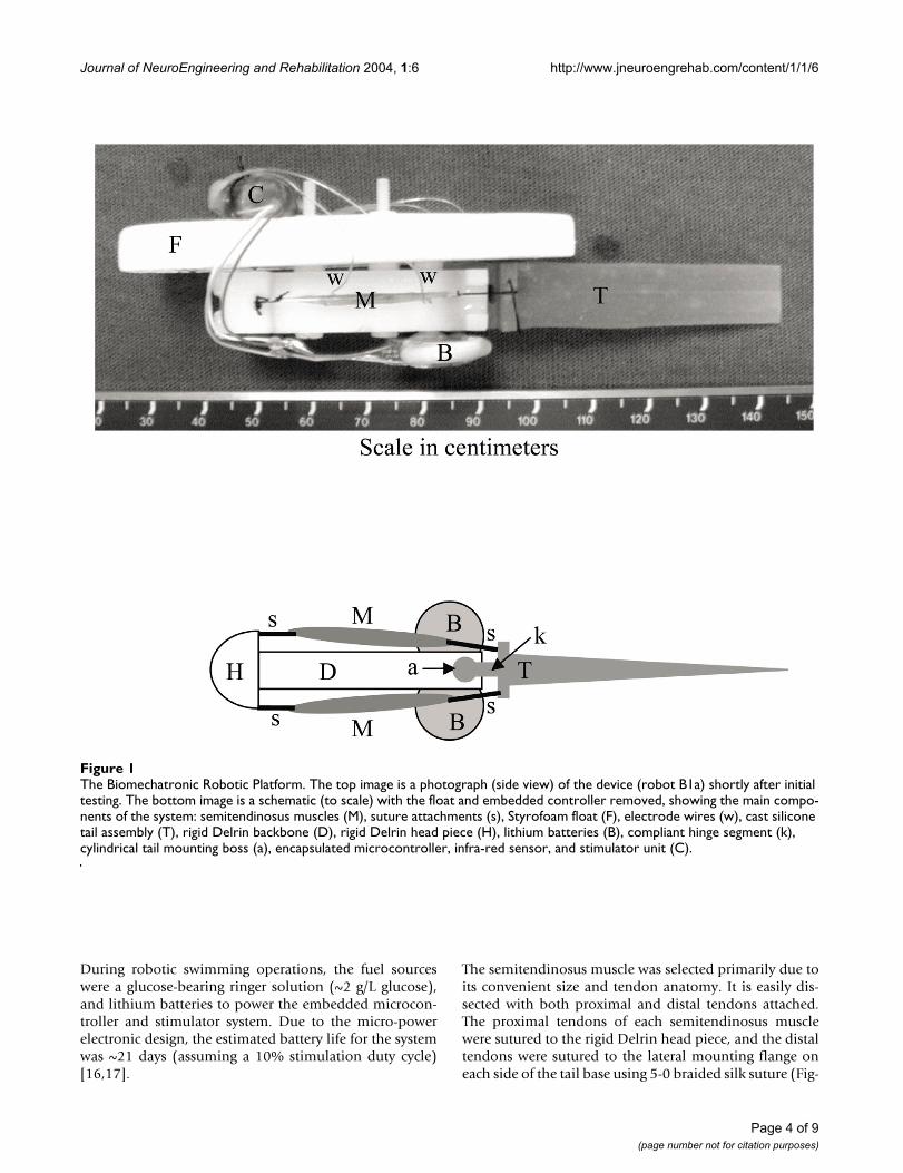
The robotic platform (Figure 1) was specifically designedto accommodate the frog semitendinosus muscles. Theactuators were a single pair of whole muscle explants fromfrog semitendinosus muscle, arranged as antagonists oneither side of the robot in an open-frame architecture. Thisopen-frame architecture exposed the explanted tissues tothe amphibian ringer solution during robot operations.The robotic platform mass before installation of the mus-cle actuators was 12.15 g, and the overall length (L) was12 cm. Of this total length, the fore or anterior 7 cm sec-tion comprised a rigid frame machined from acetyl (Del-rin) with nylon threaded fasteners, while the aft orposterior 5 cm section comprised a compliant cast sili-cone tail. A closed-cell Styrofoam float was affixed to therigid forward section to provide positive buoyancy. Thecompliant tail had a narrow rectangular section betweenthe mounting flange and the insertion to the rigid Delrinbackbone. This compliant segment (Figure 1) served as ahinge for single degree-of-freedom actuation, permittingmediolateral oscillations of the tail. This narrow compli-ant section also provided a restoring force to return the tailto its neutral position when no muscle force was applied.
The single part silicone RTV (Dow Corning type 734 flow-able silicone) tails were cast using a 5-part virgin Teflonmold machined to form a single solid tail assembly withall of the features shown in Figure 1. Casting of one-partsilicones was accelerated by the addition of ~1 drop ofwater-based food coloring per 10 ml of silicone elastomer.This technique allowed tails of different mechanical prop-erties to be readily color-coded during casting, andallowed the elastomer to be fully polymerized and setthroughout the entire cross section within 15 minutes ofinitial mixing. Castings of this sort are not biocompatiblefor several days due to the emission of acetic acid. Ifplaced in an aqueous environment too quickly with a liv-ing tissue, tissue damage would inevitably result. Thickersections require longer waiting periods, but we found thatstorage on the shelf for at least one week prior to use wassufficient to achieve biocompatibility with no noticeableeffects on the explanted tissues. The cylindrical mountingboss permitted different tail assemblies to be inserted orremoved, simply by pressing the boss into a cylindricalreceptacle in the Delrin spine. A 0.07 mm diametric inter-ference fit was used. The tail mold allowed different taillengths and base thicknesses to be cast by simply changingthe two Teflon plates that formed the sides of the triangu-lar mold cavity, allowing easy adjustment of the tail com-
pliance. The final tail geometry resulted in sufficientcompliance to allow the tail to assume a sigmoidal shape,with a wave traveling caudally when actuated in water atfrequencies above ~2 Hz. After design iterations, thespring constant of the compliant tail was 0.42 New-ton*cm/radian, and the stiffness remained the samethroughout all subsequent experimental sessions.
The onboard electronics were based upon a previouslypublished design for an implantable muscle stimulator[16], and thus the circuit architecture will not be repro-duced here. Several minor modifications were made to thecircuit hardware. The MAX630 DC-DC converter was notused. The system was powered by two 3 Volt, 48 mAhtabbed lithium batteries (Panasonic # BR1225-1VC) con-nected in series. The actual operating voltage of the batter-ies was ~2.8 V [16,17]. The embedded microprocessor(PIC16C54A, SSOP package), was operated from only thefirst battery in the series, at 2.8 VDC with a 40 kHz crystaloscillator to minimize the power consumption of thedevice [16,17]. The stimulator output buffer was poweredby both lithium batteries in series and was constructedusing logic level HEXFETs (International Rectifier #IRF7105) to provide capacitive discharge square pulsestimulation to each actuator at ~5.6 V. The pulse was suf-ficient to elicit a sub-maximal contraction of each semi-tendinosus muscle. To minimize the size of the on-boardcontrol electronics, a PC board was not used, rather eachcomponent was soldered by hand directly to the leads ofeach IC chip with jumper wires added as necessary.
Stimulation was controlled remotely via a unidirectionalinfra red (IR) link from a hand-held command module.The on-board fixed stimulation parameters were: ampli-tude = 5.8 V (alternating bipolar) [16], frequency = 80 Hz,pulse width = 100 µsec. The remote command moduleallowed for manual control of the onset of stimulation,the train duration (0 to 2550 ms, in 10 ms increments),the dwell time (time between stimulus trains (0 to 2550ms, in 10 ms increments), and a setting to control eitheralternating stimulation between the antagonistic actua-tors for forward motion, or continuous one-sided muscleactivation for steering control.
The electrodes were fashioned from medical grade TFEcoated 40 AWG stainless steel multi-strand electrode wire(Cooner Wire). The distal ends were stripped to allow theelectrode wire to be wrapped around each muscle, asdescribed previously [16]. The finished on-board controlmodules were encapsulated using electronic grade epoxy,followed by 6 coats of Dow silicone elastomer #734 dis-persed with toluene, according to the method describedpreviously [17].
Page 3 of 9(page number not for citation purposes)
Journal of NeuroEngineering and Rehabilitation 2004, 1:6 http://www.jneuroengrehab.com/content/1/1/6
During robotic swimming operations, the fuel sourceswere a glucose-bearing ringer solution (~2 g/L glucose),and lithium batteries to power the embedded microcon-troller and stimulator system. Due to the micro-powerelectronic design, the estimated battery life for the systemwas ~21 days (assuming a 10% stimulation duty cycle)[16,17].
The semitendinosus muscle was selected primarily due toits convenient size and tendon anatomy. It is easily dis-sected with both proximal and distal tendons attached.The proximal tendons of each semitendinosus musclewere sutured to the rigid Delrin head piece, and the distaltendons were sutured to the lateral mounting flange oneach side of the tail base using 5-0 braided silk suture (Fig-
The Biomechatronic Robotic PlatformFigure 1The Biomechatronic Robotic Platform. The top image is a photograph (side view) of the device (robot B1a) shortly after initial testing. The bottom image is a schematic (to scale) with the float and embedded controller removed, showing the main compo-nents of the system: semitendinosus muscles (M), suture attachments (s), Styrofoam float (F), electrode wires (w), cast silicone tail assembly (T), rigid Delrin backbone (D), rigid Delrin head piece (H), lithium batteries (B), compliant hinge segment (k), cylindrical tail mounting boss (a), encapsulated microcontroller, infra-red sensor, and stimulator unit (C).
Page 4 of 9(page number not for citation purposes)

Journal of NeuroEngineering and Rehabilitation 2004, 1:6 http://www.jneuroengrehab.com/content/1/1/6
ure 1). The muscles were mounted symmetrically onopposite sides of the robotic platform to act as antago-nists, providing a single degree-of-freedom reversibleactuator for the base of the compliant tail. Muscle lengthwas adjusted manually during installation by sliding thesutures through the tail flange to achieve the desired mus-cle length. Both muscle lengths were adjusted to set eachmuscle at rest length when the tail was in its neutral posi-tion. With no muscle force applied, the restoring torque ofthe silicone hinge-joint returned the tail to the neutralposition, thus both muscles were at their rest length whenneither was activated. This important feature is essentialfor muscle maintenance, as muscles maintained atstretched lengths are known to degenerate more rapidlythan muscles held at lengths corresponding to the ascend-ing limb of the length-tension curve [14].
Robotic Experiments and Performance CharacterizationsTwo robotic platforms were evaluated in terms of muscleactuator performance, swimming efficiency and locomo-tory maneuverability. Each robotic platform was desig-nated "B1x", where "x" indicated the build-up, serializedas "a, b, c, ..." for each subsequent pair of explanted frogmuscles. Two build-ups were constructed, B1a and B1b,each with a separate pair of freshly explanted frog semi-tendinosus muscles.
Prior to swimming evaluations, two liters of ringer solu-tion (ringer composition in Methods: Muscle Removal andMaintenance) were poured into the test tank, providing afluid depth of approximately 2.1 cm, enough for the robotto swim without touching the bottom of the tank. Thetank temperature was measured but not controlled, andwas allowed to stabilize at room temperature, approxi-mately 22°C for the duration of each experiment. Theringer solution was aerated with unfiltered room air using4 standard porous stone fish tank aerators, one placed ateach corner of the tank, and connected to an aquariumaeration pump via silicone tubing. Aeration was discon-tinued briefly before each test run to minimize turbulencein the test tank. For each robotic build-up, or for each pairof explanted semitendinosus muscles, the test tank ringersolution was not replaced or replenished for the entiretyof the robotic experimental session.
Muscle installation was carried out with the robotic plat-form partially immersed in ringer solution using #5 for-ceps (Fine Science Tools). After installation was complete,the muscles were allowed to acclimate for a period ofapproximately 5 minutes before stimulation. The robotwas manually placed to allow forward motion throughthe bath, and muscle stimulus parameters, specificallystimulus train duration and dwell time, were varied man-ually until the maximum swimming velocity wasachieved. To increase swimming speed, dwell period was
decreased and train duration was increased until furtherdecreases in dwell time or further increases in train dura-tion did not result in additional increases in forwardswimming speed. During experimentation, swimmingspeed was determined by measuring the amount of timerequired for the robot to swim across a known, fixed dis-tance. Once the maximum swimming speed was achieved,the ventral view of the swimming robot was filmed (SonyModel #DCR-TRV820; 30 frames/sec), and the film wasthen digitized to determine tail-beat frequency, tail ampli-tude, and the wave speed and wave length of the propul-sive body wave. In addition to forward straight-lineswimming, muscle stimulus parameters were varied toinvestigate turning maneuvers. At a maximum forwardswimming speed, the robot's open loop, alternating stim-ulation pattern between the antagonistic actuators wasswitched to a continuous one-sided muscle activation forsteering control, causing the robot to turn in the directionof the single stimulated muscle (a medial turn resultingfrom one-sided medial muscle stimulation). Here again,the ventral view of the swimming robot was filmed, andthe film was then digitized to determine the maximumturning radius.
For each tail-beat period, at least 10 video frames werecaptured, separated in time by 33 ms, depending on theswimming speed of the robot. A customized software pro-gram was used to digitize 10 points on each side of theoutline of the ventral silhouette of the robot, for a total of20 points for each image. A series of cubic spline functionswere used to draw the best-fit line along these points[18,19], and a midline was constructed. Tail-beat fre-quency was measured by tracking a digitized point on thetail tip from the ventral view over the course of one tail-beat cycle and dividing by the elapsed time. Tail ampli-tude was determined by measuring the tip-to-tip lineardistance at the two extremes of tail excursion and thendividing by two. As described by [20], mean propulsivewavelength was measured directly from the reconstructedmidlines as the distance between two successive peakspresent on the robot's body. Propulsive wave speed wascalculated by dividing the distance between the anteriormost point of the body exhibiting undulation and the tailtip by the time required for the crest of the wave to passthrough these points.
To estimate the overall mechanical swimming efficiencyof each robotic build-up, we calculated the robot's slipvalue, a dimensionless velocity [21]. A high slip valueindicates a larger contribution to rearward, thrust-produc-ing forces than lateral forces. Slip was calculated by divid-ing the robot's steady state swimming velocity by itspropulsive wave speed.
Page 5 of 9(page number not for citation purposes)

Journal of NeuroEngineering and Rehabilitation 2004, 1:6 http://www.jneuroengrehab.com/content/1/1/6
To estimate muscle actuator performance at the maxi-mum swimming speed, muscle strain and shorteningvelocity were estimated using the tail-beat frequency andamplitude measurements taken from the digitized films.After the swimming experiments were finalized, thechange in linear distance between the robot's muscleattachment points was measured when the robot's tail wasre-positioned from a neutral, straight position to the tailamplitude posture measured during straight-line swim-ming. As an estimate of peak muscle shortening strain,this linear-distance change was then divided by the mus-cle's resting length, or the muscle belly length when thetail was held straight (resting length measurement proto-col defined in Methods: Muscle Removal and Maintenance).Still further, to estimate muscle-shortening velocity at themaximum swimming speed, the measured linear-distancechange between muscle attachment points was divided bythe time required for the tail to re-position from a neutral,straight position to the tail amplitude posture measuredduring straight-line swimming. This time period wasmeasured from the digitized films and was equal toapproximately one quarter of a tail-beat period.
For the turning maneuvers, the turning radius was esti-mated from the ventral video images by tracking the spa-tial trajectory of a point midway between the tail tip andthe nose of the robot, a distance 6 cm from the tail tipalong the midline of the robot when the tail assumed aneutral, straight orientation. The turning radius was theradius of a circle with an arc curvature equivalent to themidpoint trajectory curvature.
Semitendinosus Contractile Experiment: Maximum Shortening VelocityTo estimate the contractile efficiency of the robotic muscleactuators at the maximum swimming velocity, a separateexperiment was conducted to determine the maximumshortening velocity of freshly dissected semitendinosusmuscles of comparable size and rest length to that of themuscles employed in robotic build-ups, B1a and B1b. Sixfreshly dissected semitendinosus muscles were placed in amuscle characterization apparatus (Aurora Model 305B)and isotonic contraction experiments [22] were con-ducted to measure the muscles' maximum shorteningvelocity. The contractile experiment was conducted at thesame temperature as the robotic experiments, or 22°C.
ResultsRobotic Performance CharacterizationsFor the B1a and B1b robotic swimmers, the locomotoryperformance parameters at maximum swimming velocityare summarized in Table 1. Table 1 also includes the mus-cle actuator mass and rest length for each robotic build-up. For both robot B1a and B1b, the total muscle mass didnot exceed 6% of the total mass of the robot (B1a = 4.8%;
B1b = 5.3%). Even with such a low relative actuator mass,swimming robots B1a and B1b achieved top speedsgreater than 1/4 and 1/3 body lengths per second, respec-tively (here the robot's total length, 12 cm, was used as thenormalization factor). For both robotic swimmers, for-ward swimming speed was readily controllable simply bydecreasing the dwell period or by increasing the trainduration. The maximum steady state, forward swimmingspeed was achieved with alternating actuator contractionsof 110 ms train duration, with 40 ms dwell periodsbetween each stimulus train, resulting in 3.1 tail-beats persecond. Further increases in the stimulus train duration orfurther decreases in the stimulus dwell time did not resultin additional increases in forward swimming speed.
Each robotic build-up was capable of the following con-trolled maneuvers: forward accelerations, decelerations,steady state gliding, and turning to the right or left. Therobot was capable of surface swimming only, so allmaneuvers were restricted to 2-dimensions. Turning wasaccomplished after forward momentum had been estab-lished by continuously activating only one actuator. Theminimum gliding turn radius was 400 mm as estimatedfrom the digitized video images of the robot's midpointtrajectory.
After swimming the full length of the test tank, the robotwas manually repositioned to the opposite end of the tankwhere it began, once again, to swim across the tank width.Typically, a period of swimming activity (~3 min) was fol-lowed by a period of swimming inactivity (~30 min). Dueto muscle fatigue, periods of inactivity were required torestore the robot's peak swimming velocity to at least 75%of its maximum value measured during the first session ofrobotic swimming (first 10 minutes of the robot'slifespan). Robot B1a swam for a sum total of 45 minutesover a 7.5 hour lifespan (10% duty cycle), after which itsswimming velocity degraded below 75% of its maximumvalue even after a 30 minute period of swimming inactiv-ity. In distinction, robot B1b swam for a much longerperiod – a sum total of 4 hours over a 42 hour lifespan(10% duty cycle) before its velocity degraded below 75%of its maximum value following a 30 minute period ofswimming inactivity.
To compare the overall swimming efficiency of eachrobotic build-up, we calculated the propeller efficiencyusing the measure of slip (swimming velocity/ propulsivewave speed) (Table 1). In a steady-state condition, at themaximum forward swimming speed, slip values forrobotic build-ups, B1a and B1b, were 0.26 and 0.32,respectively. By comparison, slip values generally increasewith swimming speed in fish, ranging from 0.2 to 0.7 inmost fish [19,20]. The mechanical swimming efficiency of
Page 6 of 9(page number not for citation purposes)

Journal of NeuroEngineering and Rehabilitation 2004, 1:6 http://www.jneuroengrehab.com/content/1/1/6
robots B1a and B1b, as determined by their respective slipvalues, were within the biological efficiency range.
Maximum Shortening Velocity and the V/Vmax Ratio at Maximum Swimming SpeedIn a separate experiment from the robotic investigations,six freshly dissected semitendinosus muscles (mass = 0.34± 0.04 g; rest length = 30 ± 1 mm; Mean ± S.E., N = 6 mus-cles) produced a maximum shortening velocity, Vmax, of78 ± 3 mm s-1 (Mean ± S.E., N = 6 muscles) in isotoniccontractions. At the maximum swimming speed, the mus-cle actuators within robots B1a and B1b experienced ashortening velocity of 25 mm s-1 (Table 1), giving a V/Vmaxratio of 0.32, an intermediate contraction velocity wheremuscle typically produces peak power and efficiency [7].
DiscussionAlthough a great deal of research has been conducted toadvance a synthetic actuator technology with muscle-likeproperties, engineering science has not yet produced amotor system that can mimic the contractility, energetics,scalability and plasticity of living muscle tissue [1,2]. Inthis investigation, we examine the feasibility of using ani-mal-derived muscle as an actuator for artificial devices. Weconstruct a simple robotic platform powered by explantedliving amphibian muscle and controlled by an embeddedmicrocontroller via an infra red data link. Using an openloop control and a simple interface design, we present pre-liminary data that suggests that living muscle might oneday be employed as a practical, controllable actuator.Hybrid robot B1b remained active for up to 42 hours, andduring that time, performed basic swimming maneuverssuch as starting, stopping, turning and straight-line swim-ming at speeds exceeding 1/3 body lengths per second.The muscle-actuated swimming robot also offered a rea-sonable swimming efficiency, as indicated by a slip valueof 0.32 (see Table 1).
Muscle Fiber Type and ControlThe frog semitendinosus muscles employed in the robotwere comprised predominantly of fast-twitch muscle fib-ers, and therefore provided higher mechanical power, atthe expense of being considerably more fatigable, thanwould have been achievable using a slow-twitch muscle ofcomparable size. Ideally, a biomechatronic swimmingrobot would incorporate several muscle fiber types to per-mit both explosive as well as low-power locomotion andmaneuvering. For the robotic platform of this investiga-tion, it is important to note that the stimulation was non-physiologic in many ways. Each muscle was stimulated inbulk, with all fibers being subjected to approximately thesame electric field. In living muscle in vivo, individualmotor axons innervate one or more muscle fibers, estab-lishing the fundamental neuromotor functional unit: amotor unit. In a sophisticated biomechatronic system, a
motor-unit level of control would be desirable (fast vs.slow), both for controllability and for tissue phenotypemaintenance.
Tissue Failure ModesIn this study, the performance of the muscle actuatorseventually degraded to the point where they were nolonger effective mechanical actuators. Several factors con-tributed to the observed tissue degradation. To begin with,explanted muscle generally has a very finite functional lifeexpectancy [14,15], usually less than one day. Excludingsuch transient failure modes as metabolic muscle fatigue,the major failure modes of muscle in vitro generally fallinto one of the following categories: (1) core necrosis dueto lack of oxygenation/capillary perfusion and large diffu-sion distances, (2) sepsis, (3) exogenous toxicity, (4) elec-tro-chemical damage resulting from excessive electricalstimulation, (5) accumulated contraction-induced injury,(6) sarcomeres heterogeneity leading to loss of thick andthin filament overlap in regions of muscle fibers (exacer-bated by prolonged periods at or above the optimal lengthfor force generation), and (7) direct mechanical damageto the muscle from external sources, such as the robotframe, attachment hardware, or electrodes.
For the tissue-actuated device of this investigation, severaldesign considerations were made to minimize many ofthese failure modes. The bath was aerated to assist oxygendelivery to the tissues, although this strategy would onlybe helpful to the outer shell of muscle fibers no greaterthan ~200 µm from the surface. In addition, the level ofmuscle cell depolarization was kept to a minimum inorder to limit electro-chemical damage [16]. Still further,the muscle actuators were attached to the robot frame atrest length in order to minimize the risk of excessive mus-cle strains and sarcomere heterogeneity. Clearly, whenlooking to the future, other failure modes must be consid-ered when very long periods of ex vivo tissue maintenanceare necessary. These include loss of muscle excitability andmass, phenotypic drift, and de-differentiation of the mus-cle from desired adult muscle phenotypes.
Muscle Actuator Source: Engineered Muscle versus Explanted TissueEven though organogenic mechanisms are poorly under-stood, it is nonetheless possible to engineer functionalmuscle organs from individual cells in culture [23-26],but currently these tissue constructs have several practicallimitations that limit their usefulness as living actuators.Among these limitations are: (1) low contractility, similarto that during early stages of muscle development, (2) lowexcitability, thus requiring large amounts of electricalenergy to adequately stimulate the tissue to contract, (3)the lack of perfusion, which limits the tissue cross sectionto a maximum radius of approximately 200 µm, and (4)
Page 7 of 9(page number not for citation purposes)
Journal of NeuroEngineering and Rehabilitation 2004, 1:6 http://www.jneuroengrehab.com/content/1/1/6
the lack of suitable tissue interfaces, both neural andmechanical. Given such technological limitations, wechose in this study to employ explanted muscle tissues forrobotic actuation. However, once these technical hurdlesare overcome, engineered muscle actuators might offerimportant advantages to the construction of biome-chatronic robots.
Future WorkThe results of this investigation, although preliminary,suggest that some degree of ex vivo robustness and lon-gevity is possible for natural muscle actuators if adequatechemical and electromechanical interventions are sup-plied from a host robotic environment. Clearly, an impor-tant area of future research will be to establish processesby which optimal intervention strategies are defined for agiven hybrid-machine task objective. Another importantarea of research will be tissue control. It has been estab-lished that natural muscle changes in size and strengthdepending on environmental work-load, and when sup-plied with appropriate signals, changes frequency charac-teristic or fiber type [9-11]. Hence, an important area offuture work will be to put forth strategies by which muscletissue plasticity can be monitored and controlled. Finally,strategies must also be devised to control the force andpower output of muscle, in the context of robotic systems,through the modulation of electrical pulses to the musclecell. To achieve the long-term objective of functional,muscle-actuated robotic and prosthetic devices, we feelcontrolling machine movements through electrical stimu-lation, harnessing muscle tissue plasticity, and maintain-ing ex vivo contractility are critical areas for futureresearch.
ConclusionIn this paper, we ask whether muscle tissue explants canbe employed as mechanical actuators for robots in themillimeter to centimeter size scale. Using a very simplecontrol and interface design, we present preliminary datathat suggests that living muscle might one day beemployed as a practical, controllable actuator. The robotof this investigation remained active for up to 42 hours,and during that time, performed basic swimming maneu-vers such as starting, stopping, turning and straight-lineswimming at speeds exceeding 1/3 body lengths per sec-ond. It is our hope that this work will lead to further stud-ies of tissue actuated robots and prostheses that will resultin an even wider range of biomechatronic machinecapabilities.
AcknowledgmentThe authors thank Dr. Richard Marsh for his invaluable assistance with the preparation of the amphibian ringer solution and the characterization of the semitendinosus frog muscle.
This work was supported by the Defense Advanced Research Projects Agency (DARPA #6890899, An Actin-Myosin Machine).
References1. Hollerbach JM, Hunter IW, Ballantyne J: A Comparative Analysis
of Actuator Technologies for Robotics. In In The Robotics ReviewEdited by: Khatib O, Craig J, Lozano-Perez T. Cambridge: MIT Press;1991:301-342.
2. Meijer K, Bar-Cohen Y, Full R: Biological Inspiration for Muscle-like Actuators of Robots. In In Biologically Inspired Intelligent RobotsEdited by: Bar-Cohen Y, Breazeal C. Bellington: SPIE Press;2003:25-41.
3. Caldwell DG: Natural and Artificial Muscle Elements AsRobot Actuators. Mechatronics 1993, 3:269-283.
4. Hannaford B, Jaax K, Klute G: Bio-inspired actuation andsensing. Autonomous Robots 2001, 11:267-272.
5. Klute GK, Czerniecki JM, Hannaford B: Artificial muscles: Actua-tors for biorobotic systems. International Journal of RoboticsResearch 2002, 21:295-309.
6. Marden JH, Allen LR: Molecules, muscles, and machines: Uni-versal performance characteristics of motors. Proceedings ofthe National Academy of Sciences of the United States of America 2002,99:4161-4166.
7. Woledge R, Curtin N, Homsher E: Energetic Aspects of MuscleContraction Bellington: Academic Press; 1985.
8. Koumans JT, Akster HA: Myogenic Cells in Development andGrowth of Fish. Comparative Biochemistry and Physiology A-Physiology1995, 110:3-20.
9. Delp MD, Pette D: Morphological-Changes During Fiber-TypeTransitions in Low-Frequency-Stimulated Rat Fast-TwitchMuscle. Cell Tissue Res 1994, 277:363-371.
10. Green HJ, Klug GA, Reichmann H, Seedorf U, Wiehrer W, Pette D:Exercise-Induced Fiber Type Transitions with Regard toMyosin, Parvalbumin, and Sarcoplasmic-Reticulum in Mus-cles of the Rat. Pflugers Archiv-European Journal of Physiology 1984,400:432-438.
11. Green HJ, Reichmann H, Pette D: Fiber Type Specific Transfor-mations in the Enzyme-Activity Pattern of Rat Vastus Later-alis Muscle by Prolonged Endurance Training. Pflugers Archiv-European Journal of Physiology 1983, 399:216-222.
12. Reichmann H, Green HJ, Pette D: Single Fiber Response to AHeavy Training Protocol in Rat Vastus Lateralis Muscle. Med-icine and Science in Sports and Exercise 1984, 16:144.
13. Pratt G: Legged Robots: What's New Since Raibert. IEEE Robot-ics and Automation Magazine. Research Perspectives 2000:15-19.
14. Harris AJ, Miledi R: Study of Frog Muscle Maintained in Organ-Culture. J Physiol 1972, 221:207-226.
15. McDonagh MJ: Mechanical properties of muscles from Xeno-pus borealis following maintenance in organ culture. CompBiochem Physiol A 1984, 77:377-382.
16. Dennis RG, Dow DE, Faulkner JA: An implantable device forstimulation of denervated muscles in rats. Medical Engineering &Physics 2003, 25:239-253.
17. Dennis RG: Bipolar implantable stimulator for long-term den-ervated-muscle experiments. Medical & Biological Engineering &Computing 1998, 36:225-228.
18. Jayne BC, Lauder GV: Speed effects on midline kinematics dur-ing steady undulatory swimming of largemouth bass, Micro-pterus salmoides. J Exp Biol 1995, 198:585-602.
19. Gillis GB: Anguilliform locomotion in an elongate salamander(Siren intermedia): effects of speed on axial undulatorymovements. J Exp Biol 1997, 200:767-784.
20. Gillis GB: Environmental effects on undulatory locomotion inthe American eel Anguilla rostrata: kinematics in water andon land. J Exp Biol 1998, 201:949-961.
21. Lighthill J: Mathematical Biofluiddynamics Philadelphia: Society forIndustrial and Applied Mathematics; 1975.
22. Bahler AS, Fales JT, Zieler KL: The dynamic properties of mam-malian skeletal muscle. J Genera Physiol 1968, 51:369-384.
23. Dennis RG, Kosnik PE: Excitability and isometric contractileproperties of mammalian skeletal muscle constructs engi-neered in vitro. In Vitro Cellular & Developmental Biology-Animal 2000,36:327-335.
24. Dennis RG, Kosnik PE, Gilbert ME, Faulkner JA: Excitability andcontractility of skeletal muscle engineered from primary cul-
Page 8 of 9(page number not for citation purposes)
http://www.ncbi.nlm.nih.gov/entrez/query.fcgi?cmd=Retrieve&db=PubMed&dopt=Abstract&list_uids=7521794
http://www.ncbi.nlm.nih.gov/entrez/query.fcgi?cmd=Retrieve&db=PubMed&dopt=Abstract&list_uids=7521794
http://www.ncbi.nlm.nih.gov/entrez/query.fcgi?cmd=Retrieve&db=PubMed&dopt=Abstract&list_uids=7521794
http://www.ncbi.nlm.nih.gov/entrez/query.fcgi?cmd=Retrieve&db=PubMed&dopt=Abstract&list_uids=6235480
http://www.ncbi.nlm.nih.gov/entrez/query.fcgi?cmd=Retrieve&db=PubMed&dopt=Abstract&list_uids=6235480
http://www.ncbi.nlm.nih.gov/entrez/query.fcgi?cmd=Retrieve&db=PubMed&dopt=Abstract&list_uids=6235480
http://www.ncbi.nlm.nih.gov/entrez/query.fcgi?cmd=Retrieve&db=PubMed&dopt=Abstract&list_uids=6657463
http://www.ncbi.nlm.nih.gov/entrez/query.fcgi?cmd=Retrieve&db=PubMed&dopt=Abstract&list_uids=6657463
http://www.ncbi.nlm.nih.gov/entrez/query.fcgi?cmd=Retrieve&db=PubMed&dopt=Abstract&list_uids=6657463
http://www.ncbi.nlm.nih.gov/entrez/query.fcgi?cmd=Retrieve&db=PubMed&dopt=Abstract&list_uids=4335913
http://www.ncbi.nlm.nih.gov/entrez/query.fcgi?cmd=Retrieve&db=PubMed&dopt=Abstract&list_uids=4335913
http://www.ncbi.nlm.nih.gov/entrez/query.fcgi?cmd=Retrieve&db=PubMed&dopt=Abstract&list_uids=6142802
http://www.ncbi.nlm.nih.gov/entrez/query.fcgi?cmd=Retrieve&db=PubMed&dopt=Abstract&list_uids=6142802
http://www.ncbi.nlm.nih.gov/entrez/query.fcgi?cmd=Retrieve&db=PubMed&dopt=Abstract&list_uids=9684464
http://www.ncbi.nlm.nih.gov/entrez/query.fcgi?cmd=Retrieve&db=PubMed&dopt=Abstract&list_uids=9684464
http://www.ncbi.nlm.nih.gov/entrez/query.fcgi?cmd=Retrieve&db=PubMed&dopt=Abstract&list_uids=9318295
http://www.ncbi.nlm.nih.gov/entrez/query.fcgi?cmd=Retrieve&db=PubMed&dopt=Abstract&list_uids=9318535

Journal of NeuroEngineering and Rehabilitation 2004, 1:6 http://www.jneuroengrehab.com/content/1/1/6
Publish with BioMed Central and every scientist can read your work free of charge
"BioMed Central will be the most significant development for disseminating the results of biomedical research in our lifetime."
Sir Paul Nurse, Cancer Research UK
Your research papers will be:
available free of charge to the entire biomedical community
peer reviewed and published immediately upon acceptance
cited in PubMed and archived on PubMed Central
yours — you keep the copyright
Submit your manuscript here:http://www.biomedcentral.com/info/publishing_adv.asp
BioMedcentral
tures and cell lines. American Journal of Physiology-Cell Physiology2001, 280:C288-C295.
25. Kosnik PE, Dennis RG: Mesenchymal Cell Culture: FunctionalMammalian Skeletal Muscle Constructs. In In Methods in TissueEngineering Edited by: Atala A, Lanza R. San Diego: Harcourt Aca-demic Press; 2002:299-306.
26. Vandenburgh HH, Swasdison S, Karlisch P: Computer-aidedmechanogenesis of skeletal muscle organs from single cellsin vitro. FASEB Journal 1991, 5:2860-2867.
Page 9 of 9(page number not for citation purposes)
http://www.ncbi.nlm.nih.gov/entrez/query.fcgi?cmd=Retrieve&db=PubMed&dopt=Abstract&list_uids=1916108
http://www.ncbi.nlm.nih.gov/entrez/query.fcgi?cmd=Retrieve&db=PubMed&dopt=Abstract&list_uids=1916108


![CHAPTER 4: ACTUATED CONTROLLER TIMING PROCESSES … · Chapter 4: Actuated Controller Timing Processes 89 [2012.12.19] CHAPTER 4: ACTUATED CONTROLLER TIMING PROCESSES This chapter](https://static.fdocuments.in/doc/165x107/5f68dd109d404110520123b9/chapter-4-actuated-controller-timing-processes-chapter-4-actuated-controller-timing.jpg)