A Survey Regarding Wireless Communication …239214/FULLTEXT01.pdfWireless Communication Standards...
51
Technical Report IDE0712, February 2007 A Survey Regarding Wireless Communication Standards Intended for a High-Speed Vehicle Environment Katrin Bilstrup School of Information Science, Computer and Electrical Engineering, Halmstad University, Box 823, SE-30118 Halmstad, Sweden
Transcript of A Survey Regarding Wireless Communication …239214/FULLTEXT01.pdfWireless Communication Standards...

Technical Report IDE0712, February 2007
A Survey Regarding
Wireless Communication Standards Intended for a High-Speed Vehicle Environment
Katrin Bilstrup
School of Information Science, Computer and Electrical Engineering, Halmstad University, Box 823, SE-30118 Halmstad, Sweden


ABSTRACT
The high velocities and dynamic conditions that a vehicular environment represents introduce new and demanding challenges in the area of wireless communication. Vehicle Alert System (VAS) is a research project at Halmstad University, Sweden, focusing on reliable wireless vehicle communication. Typical examples of applications for a vehicle alert system are pre-crash warning, communicating slippery road conditions, emergency vehicle routing etc. In VAS a set of application scenarios have been chosen specifically to illustrate as many interesting research aspects of a vehicle alert system as possible. The chosen scenarios include both vehicle-to-vehicle and vehicle-to-infrastructure communications. Research is conducted on all layers of the communication stack relevant for a vehicle alert system – application, network, data link and the physical layer. From a communication perspective a vehicle alert system is characterized by short event-driven control messages that have to be received without errors in time. This implies that different coding strategies, diversity and retransmission schemes must be used to achieve correctness and robustness against the impairments of the wireless channel. This survey presents and discusses different wireless communication standards as well as proprietary solutions that are intended especially for a high-speed vehicular environment. Since VAS is aiming for real-time wireless communication, the examined standards will be evaluated accordingly. Real-time communication implies that there is an upper bound on the communication delay such that if the data never reaches its intended recipient before a certain deadline this will have a more or less negative impact on the system performance. One of the most important features of a real-time communication system (and perhaps even more crucial in a wireless high-speed vehicular environment) is the medium access method. If it is not deterministic (i.e., if there exists no upper bound on the delay before a station gets access to the wireless channel) it is not possible to give guarantees about meeting the deadlines. All currently existing standards, draft specifications and proprietary solutions with explicit intention for being used in a vehicular environment are covered in this survey. In preparation of this document the standard/draft documents themselves have been studied and for proprietary solutions the respective company’s home pages and in some cases articles have been used for collecting information. One of the currently most discussed standards is the draft IEEE 802.11p which has been thoroughly studied here. It inherits features from the Quality of Service amendment IEEE 802.11e and the physical layer supplement IEEE 802.11a. The full protocol suite WAVE, also developed by IEEE, incorporates the 802.11p. Other standards, drafts and proprietary solutions that have been studied are IEEE 802.16, IEEE 802.20, flash-OFDM, national DSCR systems, CALM and IEEE 802.21. These systems range from being simple RFID-look-a-like DSRC systems to more advanced centralized WMAN standards. It can be concluded that none of the standards or proprietary solutions described in this survey is suitable for applications such as those considered in the VAS research project. Within the different standards there certainly are features suitable for a vehicle alert system but no standard totally fit the requirements of VAS. One lacking feature common for all standards investigated is the ability of providing deterministic medium access for vehicle-to-vehicle communication.


TABLE OF CONTENTS
1 INTRODUCTION ....................................................................................................................................... 1
2 IEEE 802.11P AND WAVE ........................................................................................................................ 5
2.1 IEEE 802.11 ......................................................................................................................................... 5 2.1.1 WiFi................................................................................................................................................. 6 2.1.2 Network topology ............................................................................................................................ 6 2.1.3 Medium access control.................................................................................................................... 6 2.1.4 Timing ............................................................................................................................................. 7
2.2 IEEE 802.11A....................................................................................................................................... 7 2.3 IEEE 802.11E ....................................................................................................................................... 9 2.4 IEEE 802.11P AND WAVE................................................................................................................. 11
3 DEDICATED SHORT RANGE COMMUNICATIONS ....................................................................... 15
3.1 EUROPEAN DSRC STANDARD............................................................................................................. 16 3.2 AMERICAN DSRC STANDARD............................................................................................................. 16
4 WIRELESS BROADBAND NETWORKS ............................................................................................. 19
4.1 STANDARDS........................................................................................................................................ 19 4.1.1 IEEE 802.16 .................................................................................................................................. 19 4.1.2 WiMAX .......................................................................................................................................... 21 4.1.3 IEEE 802.20 .................................................................................................................................. 21 4.1.4 WiBro ............................................................................................................................................ 22
4.2 PROPRIETARY SOLUTIONS................................................................................................................... 22 4.2.1 Flash-OFDM................................................................................................................................. 22 4.2.2 iBurst ............................................................................................................................................. 23
5 CALM......................................................................................................................................................... 25
6 IEEE 802.21................................................................................................................................................ 27
7 DISCUSSION............................................................................................................................................. 29
8 CONCLUSION .......................................................................................................................................... 31
9 ABBREVIATIONS/ACRONYMS ........................................................................................................... 33
10 REFERENCES .......................................................................................................................................... 35
APPENDIX A – TIMING IN IEEE 802.11....................................................................................................... 37
APPENDIX B – IEEE 802.11 AMENDMENTS AND SUPPLEMENTS....................................................... 39
APPENDIX C – CLAUSE OVERVIEW IEEE 802.11 .................................................................................... 41
APPENDIX D – STANDARD BODIES AROUND THE WORLD................................................................ 43
CEN.................................................................................................................................................................. 43 ETSI ................................................................................................................................................................. 44 ISO ................................................................................................................................................................... 45

A Survey Regarding Wireless Communication Standards Intended for a High-Speed Vehicle Environment
Katrin Bilstrup, Halmstad University, Sweden, 2007 1
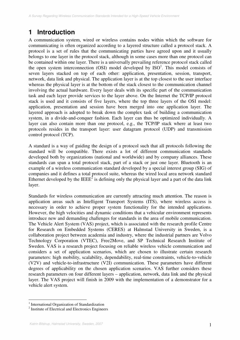
1 Introduction A communication system, wired or wireless contains nodes within which the software for communicating is often organized according to a layered structure called a protocol stack. A protocol is a set of rules that the communicating parties have agreed upon and it usually belongs to one layer in the protocol stack, although in some cases more than one protocol can be contained within one layer. There is a universally prevailing reference protocol stack called the open system interconnection (OSI) model developed by ISO1. This model consists of seven layers stacked on top of each other: application, presentation, session, transport, network, data link and physical. The application layer is at the top closest to the user interface whereas the physical layer is at the bottom of the stack closest to the communication channel involving the actual hardware. Every layer deals with its specific part of the communication task and each layer provide services to the layer above. On the Internet the TCP/IP protocol stack is used and it consists of five layers, where the top three layers of the OSI model: application, presentation and session have been merged into one application layer. The layered approach is adopted to break down the complex task of building a communication system, in a divide-and-conquer fashion. Each layer can thus be optimized individually. A layer can also contain more than one protocol, e.g., the TCP/IP stack where at least two protocols resides in the transport layer: user datagram protocol (UDP) and transmission control protocol (TCP). A standard is a way of guiding the design of a protocol such that all protocols following the standard will be compatible. There exists a lot of different communication standards developed both by organizations (national and worldwide) and by company alliances. These standards can span a total protocol stack, part of a stack or just one layer. Bluetooth is an example of a wireless communication standard developed by a special interest group (SIG) of companies and it defines a total protocol suite, whereas the wired local area network standard Ethernet developed by the IEEE2 is defining only the physical layer and a part of the data link layer. Standards for wireless communication are currently attracting much attention. The reason is application areas such as Intelligent Transport Systems (ITS), where wireless access is necessary in order to achieve proper system functionality for the intended applications. However, the high velocities and dynamic conditions that a vehicular environment represents introduce new and demanding challenges for standards in the area of mobile communication. The Vehicle Alert System (VAS) project, which is associated with the research profile Centre for Research on Embedded Systems (CERES) at Halmstad University in Sweden, is a collaboration project between academia and industry, where the industrial partners are Volvo Technology Corporation (VTEC), Free2Move, and SP Technical Research Institute of Sweden. VAS is a research project focusing on reliable wireless vehicle communication and considers a set of application scenarios, which are chosen to illustrate certain research parameters: high mobility, scalability, dependability, real-time constraints, vehicle-to-vehicle (V2V) and vehicle-to-infrastructure (V2I) communication. These parameters have different degrees of applicability on the chosen application scenarios. VAS further considers these research parameters on four different layers – application, network, data link and the physical layer. The VAS project will finish in 2009 with the implementation of a demonstrator for a vehicle alert system.
1 International Organization of Standardization 2 Institute of Electrical and Electronics Engineers

A Survey Regarding Wireless Communication Standards Intended for a High-Speed Vehicle Environment
Katrin Bilstrup, Halmstad University, Sweden, 2007 2
This survey is a deliverable from a work package belonging to the VAS project. The purpose is to present and discuss the different features and components that are included in the wireless networking standards that are intended for vehicular environments (these standards typically only include the data link layer and the physical layer). The pros and cons together with some problems and potential solutions are pointed out. In particular, these standards will be scrutinized to determine whether they would fit a VAS system, i.e., if they support real-time wireless communication. Real-time does not mean runtime, but something that has a deadline that has to be met in order for a system to behave correctly. A real-time communication task does not have to be sent fast, with a high transmission rate, but it does require the message to be delivered before the deadline. Obviously, a low average delay is beneficial also in real-time systems. Communicating to avoid or mitigate traffic accidents in a VAS system has very strict deadlines. For safety applications, it is important that the packet loss rate is low and that there is an upper limit on the maximum delay that can occur, in order to know whether the deadline can be kept. High bandwidth, high throughput or a high transfer rate can be of help when creating robust schemes with lower packet loss rates since this gives the possibility of reducing the average delay. But systems such as these still does not imply any limit on the maximum delay that can occur. One of the most important features of a wireless real-time communication system is therefore the medium access method. If it is not deterministic, i.e., an upper bound on delay before a station gets access to the wireless channel exists, there is no possibility to give any guarantees about meeting any deadlines. There is currently a tremendous interest in standards concerning wireless communication for ITS and especially applications including V2V communication intended for exchanging real-time messages about dangerous situations like upcoming crashes. There already exists application specific standards for ITS, such as electronic toll collection and automatic vehicle identification. These are quite simple RFID-look-a-like standards defining a whole protocol stack containing three layers: physical, data link, and application layer. The reduced stack is used in order to keep the delay and complexity low. These particular standards are referred to as dedicated short-range communications (DSRC) and different parts of the world have their own definition of DSRC and their own standard (e.g., Europe, Korea, US, Japan). The DSRC network is simple, contains hotspots and no handover between different hotspots are necessary. The hotspots can for example be placed where a road fee is collected requiring the vehicle to have some kind of equipment (i.e., a transponder) to be able to use this feature. These networks are not intended for V2V communications, but mainly for V2I or even vehicle-to-hotspot communication. The next step for ITS standards is the upcoming IEEE 802.11p standard, which together with the Wireless Access in Vehicular Environment (WAVE) profile will be able to provide more advanced services such as, e.g., Internet access and alerting drivers about approaching emergency vehicles. The 802.11p is an amendment to the wireless local area network (WLAN) standard IEEE 802.11, which defines the physical layer and a sublayer to the data link layer called the medium access control layer. The 802.11p will use the physical layer standard of 802.11a and parts of the amendment 802.11e intended to provide quality of service (QoS). WAVE entails an entire protocol stack developed by the IEEE which also incorporates 802.11p. IEEE 802.16, IEEE 802.20, WiBro, flash-OFDM and iBurst, are all examples of wireless metropolitan area networks (WMAN), both proprietary company solutions and approved/unapproved standards by different organizations intended for a vehicular environment. Common for all these protocols is; they are centralized, they support handover
A Survey Regarding Wireless Communication Standards Intended for a High-Speed Vehicle Environment
Katrin Bilstrup, Halmstad University, Sweden, 2007 3
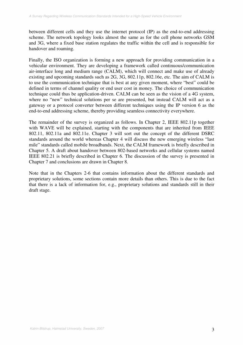
between different cells and they use the internet protocol (IP) as the end-to-end addressing scheme. The network topology looks almost the same as for the cell phone networks GSM and 3G, where a fixed base station regulates the traffic within the cell and is responsible for handover and roaming. Finally, the ISO organization is forming a new approach for providing communication in a vehicular environment. They are developing a framework called continuous/communication air-interface long and medium range (CALM), which will connect and make use of already existing and upcoming standards such as 2G, 3G, 802.11p, 802.16e, etc. The aim of CALM is to use the communication technique that is best at any given moment, where “best” could be defined in terms of channel quality or end user cost in money. The choice of communication technique could thus be application-driven. CALM can be seen as the vision of a 4G system, where no “new” technical solutions per se are presented, but instead CALM will act as a gateway or a protocol converter between different techniques using the IP version 6 as the end-to-end addressing scheme, thereby providing seamless connectivity everywhere. The remainder of the survey is organized as follows. In Chapter 2, IEEE 802.11p together with WAVE will be explained, starting with the components that are inherited from IEEE 802.11, 802.11a and 802.11e. Chapter 3 will sort out the concept of the different DSRC standards around the world whereas Chapter 4 will discuss the new emerging wireless “last mile” standards called mobile broadbands. Next, the CALM framework is briefly described in Chapter 5. A draft about handover between 802-based networks and cellular systems named IEEE 802.21 is briefly described in Chapter 6. The discussion of the survey is presented in Chapter 7 and conclusions are drawn in Chapter 8. Note that in the Chapters 2-6 that contains information about the different standards and proprietary solutions, some sections contain more details than others. This is due to the fact that there is a lack of information for, e.g., proprietary solutions and standards still in their draft stage.

A Survey Regarding Wireless Communication Standards Intended for a High-Speed Vehicle Environment
Katrin Bilstrup, Halmstad University, Sweden, 2007 4

A Survey Regarding Wireless Communication Standards Intended for a High-Speed Vehicle Environment
Katrin Bilstrup, Halmstad University, Sweden, 2007 5
2 IEEE 802.11p and WAVE The IEEE 802.11 standard was released for the first time 1997 and is a wireless local area network (WLAN) standard. It defines a medium access control (MAC) layer and physical (PHY) layer [1]. Since this release, three extensions to the physical layer have been made – 802.11a, 802.11b and 802.11g. The 802.11 standard is a member of the IEEE 802 LAN standard family. The IEEE 802.11p is a new upcoming standard and this will be an extension to 802.11 intended for a high-speed vehicular environment. The 802.11p will use the MAC amendment3 802.11e for quality of service (QoS) support and the PHY supplement4 802.11a. In order to grasp the 802.11p standard, Section 2.1 will start with explaining vital parts of the legacy 802.11 standard used in 802.11p. The PHY of 802.11a is explained in Section 2.2 and the parts of the 802.11e QoS used in 802.11p are explained in Section 2.3. The chapter is concluded with the draft of 802.11p together with the protocol stack wireless access in vehicular environment (WAVE).
2.1 IEEE 802.11 The IEEE 802 LAN standards, Figure 1, which includes IEEE 802.11 and IEEE 802.3 among others, use the same bridging protocol, IEEE 802.1, and the same logical link control (LLC) in the logical link sublayer, IEEE 802.2. This separation between logical link and MAC/PHY makes it possible to overcome the differences in medium and network topology between the different LAN standards. This construction simply hides the differences between the various network types. The purpose of LLC is to exchange data between end users across a LAN using 802-based MAC controlled link. The LLC provides three services for the network layer; unacknowledged connection-less service, acknowledged connection-less service and connection-oriented service.
Figure 1. An overview of the IEEE 802 LAN Family.
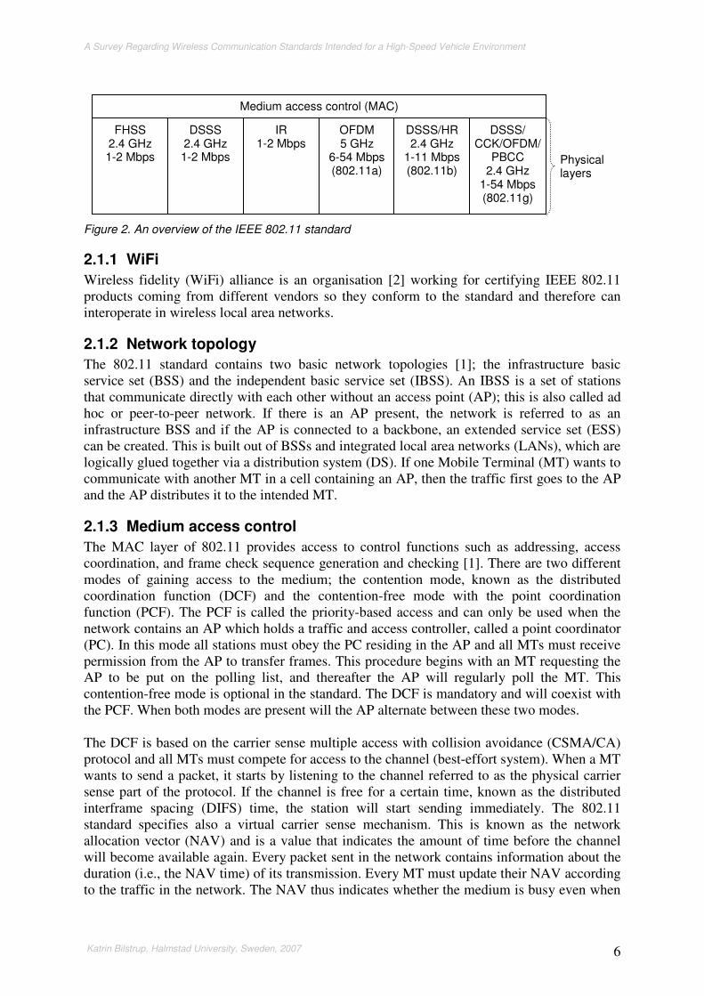
There are six different physical layers to 802.11, Figure 2; frequency hopping spread spectrum (FHSS), direct sequence spread spectrum (DSSS), infrared (IR), orthogonal frequency division multiplexing (OFDM), DSSS/high rate (DSSS/HR) and OFDM/DSSS/complementary code keying (CCK)/packet binary convolutional coding (PBCC). In Figure 2 the different data rates, modulation types and the operating frequency are depicted. The FHSS, DSSS, and IR physical layers were released together with the base standard in 1997 whereas the other three are extensions to the base standard.
3 An amendment is a correction/improvement of an already existing work. 4 A supplement is an addition to an already existing work.
Physical
Media Access
Logical link
IEEE 802.1 Bridging
IEEE 802.3
Ethernet
IEEE 802.4
Token bus
IEEE 802.5 Token
ring
IEEE
802.11 Wireless
IEEE 802.2 Logical Link Control
Data link layer
A Survey Regarding Wireless Communication Standards Intended for a High-Speed Vehicle Environment
Katrin Bilstrup, Halmstad University, Sweden, 2007 6
Figure 2. An overview of the IEEE 802.11 standard
2.1.1 WiFi
Wireless fidelity (WiFi) alliance is an organisation [2] working for certifying IEEE 802.11 products coming from different vendors so they conform to the standard and therefore can interoperate in wireless local area networks.
2.1.2 Network topology
The 802.11 standard contains two basic network topologies [1]; the infrastructure basic service set (BSS) and the independent basic service set (IBSS). An IBSS is a set of stations that communicate directly with each other without an access point (AP); this is also called ad hoc or peer-to-peer network. If there is an AP present, the network is referred to as an infrastructure BSS and if the AP is connected to a backbone, an extended service set (ESS) can be created. This is built out of BSSs and integrated local area networks (LANs), which are logically glued together via a distribution system (DS). If one Mobile Terminal (MT) wants to communicate with another MT in a cell containing an AP, then the traffic first goes to the AP and the AP distributes it to the intended MT.
2.1.3 Medium access control
The MAC layer of 802.11 provides access to control functions such as addressing, access coordination, and frame check sequence generation and checking [1]. There are two different modes of gaining access to the medium; the contention mode, known as the distributed coordination function (DCF) and the contention-free mode with the point coordination function (PCF). The PCF is called the priority-based access and can only be used when the network contains an AP which holds a traffic and access controller, called a point coordinator (PC). In this mode all stations must obey the PC residing in the AP and all MTs must receive permission from the AP to transfer frames. This procedure begins with an MT requesting the AP to be put on the polling list, and thereafter the AP will regularly poll the MT. This contention-free mode is optional in the standard. The DCF is mandatory and will coexist with the PCF. When both modes are present will the AP alternate between these two modes. The DCF is based on the carrier sense multiple access with collision avoidance (CSMA/CA) protocol and all MTs must compete for access to the channel (best-effort system). When a MT wants to send a packet, it starts by listening to the channel referred to as the physical carrier sense part of the protocol. If the channel is free for a certain time, known as the distributed interframe spacing (DIFS) time, the station will start sending immediately. The 802.11 standard specifies also a virtual carrier sense mechanism. This is known as the network allocation vector (NAV) and is a value that indicates the amount of time before the channel will become available again. Every packet sent in the network contains information about the duration (i.e., the NAV time) of its transmission. Every MT must update their NAV according to the traffic in the network. The NAV thus indicates whether the medium is busy even when
FHSS 2.4 GHz 1-2 Mbps
DSSS 2.4 GHz 1-2 Mbps
IR 1-2 Mbps
OFDM 5 GHz
6-54 Mbps (802.11a)
DSSS/HR 2.4 GHz
1-11 Mbps (802.11b)
DSSS/ CCK/OFDM/
PBCC 2.4 GHz
1-54 Mbps (802.11g)
Medium access control (MAC)
Physical layers

A Survey Regarding Wireless Communication Standards Intended for a High-Speed Vehicle Environment
Katrin Bilstrup, Halmstad University, Sweden, 2007 7
the channel does not appear to be busy as sensed by the physical carrier sense. These two carrier sense mechanisms make the collision avoidance part in the protocol. If an MT senses that the medium is busy, either virtually or physically, the station must randomize a backoff time before a transmission can be initiated anew. As long as the channel is free the MT decrements the backoff time and when it reaches zero the MT starts sending right away. This backoff procedure is used to prevent collisions among MTs, and hence the highest probability of collisions is right after a busy channel – especially during high utilisation periods. The probability of collisions will, however, decrease if the MTs have different backoff times. Each time a MT has failed to send a medium access protocol data unit (MPDU)/packet due to a busy channel or a collision, the MT must follow the backoff procedure [1]. The MT starts with randomising a backoff time based on a slot time (in the standard called aSlotTime). The slot time is derived from the specification of the PHY in use. As an example, when IEEE
802.11a OFDM is used, the slot time is 9 µs. The slot time accounts for propagation delay, for the time needed to switch from receiving to transmitting state, and the time it takes to signal to the MAC layer the state of the channel. The backoff time is calculated as a random integer multiplied with the slottime. The random element is uniformly distributed in the interval [0, CW] where CW stands for contention window. The size of the CW is also derived from the physical specification. In the case with OFDM, the initial CW is set to 15 (aCWmin). The
maximum backoff time for an initial attempt to access the channel will therefore be 135 µs. The CW is doubled for every attempt to retransmit a particular MPDU up to the maximum CW, which is 1023 (aCWmax) in the OFDM case and this will give a maximum backoff time
of 9207 µs. The increasing CW is useful during high utilisation periods, when a lot of MTs wants to access the channel. With a large CW there will be greater spread of the randomized backoff times for the MTs and thus collisions will decrease. After a successful MPDU transmission the CW will be set to its initial value again. The randomized backoff time is decremented only when the channel is free.
2.1.4 Timing
Interframe space (IFS) refers to the time between packets. There are four different interframe spaces; short interframe space (SIFS), PCF interframe space (PIFS), DCF interframe space (DIFS) and extended interframe space (EIFS). These provide different priority levels for accessing the channel. The SIFS is the shortest time period whereas the EIFS is the longest interval. The actual value of the different IFS is determined by the PHY in use. In Appendix A the different interframe spaces and their values derived from the different physical layers are shown. The amendment IEEE 802.11e [3] introduces a new timing parameter called the arbitration interframe space (AIFS) and this is used in order to provide different levels of QoS, see Section 2.3.
2.2 IEEE 802.11a The IEEE 802.11a uses OFDM. OFDM is a multi-carrier transmission technique that dates back to the 60’s and is used in both wireless and wired systems. In the wired case, it is referred to as discrete multi-tone (DMT). The basic idea with OFDM is to divide the available frequency spectrum into narrower subchannels (subcarriers). The high-rate data stream is split into a number of lower-rate data streams transmitted simultaneously over a number of subcarriers, where each subcarrier is narrow banded. OFDM can handle frequency selective fading better than a single-carrier system, and avoids the problem when a single fade or interferer can break an entire link.
A Survey Regarding Wireless Communication Standards Intended for a High-Speed Vehicle Environment
Katrin Bilstrup, Halmstad University, Sweden, 2007 8
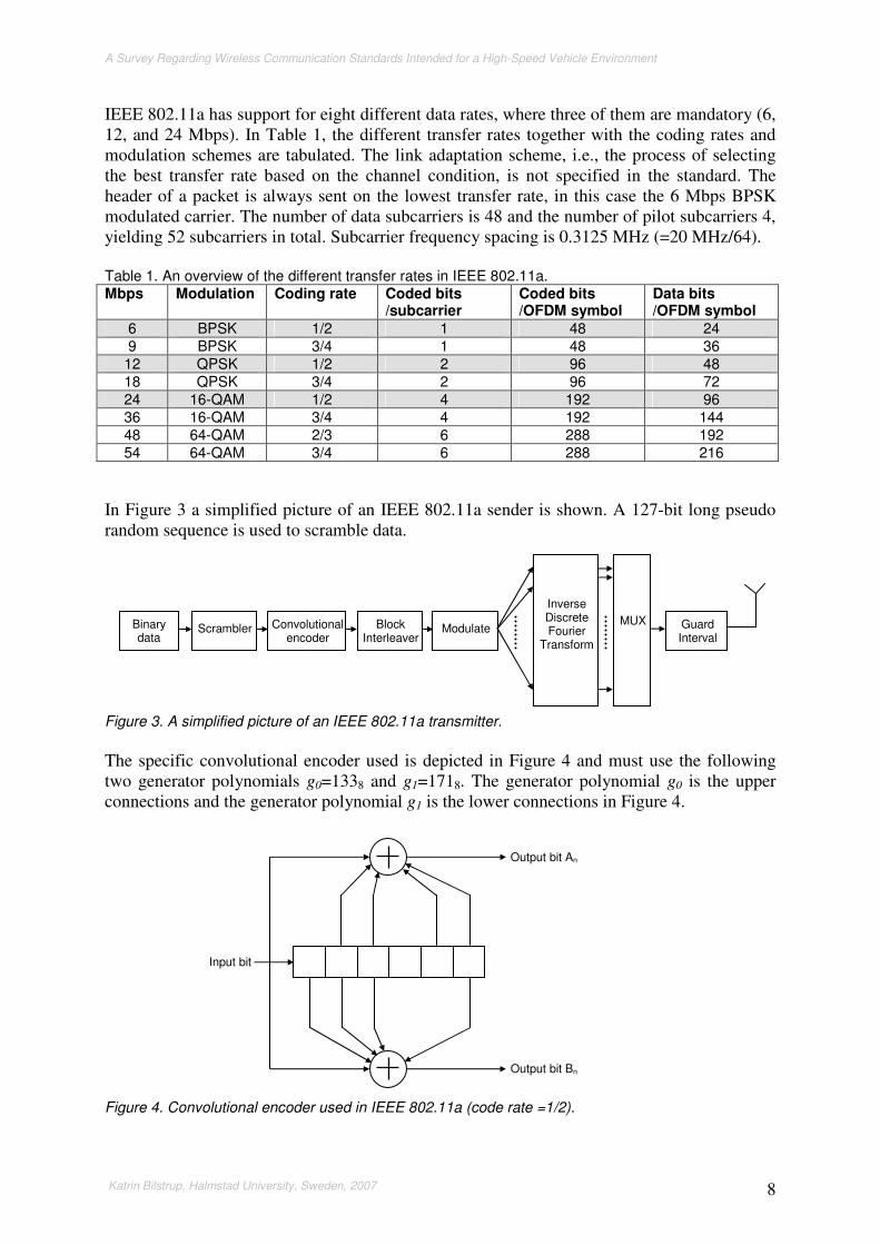
IEEE 802.11a has support for eight different data rates, where three of them are mandatory (6, 12, and 24 Mbps). In Table 1, the different transfer rates together with the coding rates and modulation schemes are tabulated. The link adaptation scheme, i.e., the process of selecting the best transfer rate based on the channel condition, is not specified in the standard. The header of a packet is always sent on the lowest transfer rate, in this case the 6 Mbps BPSK modulated carrier. The number of data subcarriers is 48 and the number of pilot subcarriers 4, yielding 52 subcarriers in total. Subcarrier frequency spacing is 0.3125 MHz (=20 MHz/64). Table 1. An overview of the different transfer rates in IEEE 802.11a. Mbps Modulation Coding rate Coded bits
/subcarrier Coded bits /OFDM symbol
Data bits /OFDM symbol
6 BPSK 1/2 1 48 24 9 BPSK 3/4 1 48 36 12 QPSK 1/2 2 96 48 18 QPSK 3/4 2 96 72 24 16-QAM 1/2 4 192 96 36 16-QAM 3/4 4 192 144 48 64-QAM 2/3 6 288 192 54 64-QAM 3/4 6 288 216
In Figure 3 a simplified picture of an IEEE 802.11a sender is shown. A 127-bit long pseudo random sequence is used to scramble data.
Figure 3. A simplified picture of an IEEE 802.11a transmitter.
The specific convolutional encoder used is depicted in Figure 4 and must use the following two generator polynomials g0=1338 and g1=1718. The generator polynomial g0 is the upper connections and the generator polynomial g1 is the lower connections in Figure 4.
Figure 4. Convolutional encoder used in IEEE 802.11a (code rate =1/2).
Input bit
Output bit An
Output bit Bn
Binary data
Scrambler Convolutional encoder
Block Interleaver
Modulate
Inverse Discrete Fourier
Transform
MUX Guard Interval

A Survey Regarding Wireless Communication Standards Intended for a High-Speed Vehicle Environment
Katrin Bilstrup, Halmstad University, Sweden, 2007 9
This code has a code rate of r=1/2 and to achieve the two higher code rates (r=2/3 and r=3/4, Table 1) two different puncturing patterns are used. These are shown in Figure 5. In Figure 5a the puncturing pattern for code rate r=3/4 is shown and in Figure 5b the puncturing pattern for code rate r=2/3 is shown.
Figure 5. Different patterns for different coding rates, (a) r=2/3 and (b) r=3/4.
The purpose of the block interleaver in Figure 3 is to make burst errors more random in order to increase the probability that the convolutional code can correct all errors. The channel characteristics decides the specific interleaving pattern and if the system is operating in an additive white Gaussian noise (AWGN) environment there is no need for interleaving since the error distribution is random already and thus cannot be changed by relocating the bits [4]. The AWGN channel is memoryless meaning that the noise affects each bit independently of each other. In a multipath environment, that is typical for WLAN, the channel is said to have memory since it is fading. This implies that the bit errors will instead appear in bursts and by using interleaving the bits will be spread in time and then the channel can be seen as memoryless. In IEEE 802.11a, a block interleaver is used and the interleaving depth is equal to one OFDM symbol decided by the modulation schemes in use, Table 1. The interleaver uses a two-stage permutation. The first step assures that adjacent code words are mapped onto non-adjacent subcarriers, whereas the second step assures that adjacent codewords are mapped alternately onto more or less significant bits of the constellation [5]. WLAN systems assume a slowly fading channel implying that the channel will stay in the same state during the entire packet transmission. This means that no additional gain can be achieved by increasing the interleaver size [4].
2.3 IEEE 802.11e This amendment adds QoS to the MAC layer in the IEEE 802.11 standard and is independent of what physical layer in use. The IEEE 802.11e defines a new medium access procedure called the hybrid coordination function (HCF). The HCF enhances the contention-based and the contention-free accesses by providing QoS, Figure 6. It also introduces a new interframe space called arbitration interframe space (AIFS).
X0 X1 X2 X3 X4 X5 X6 X7
A0 A1 A2 A3 A4 A5 A6 A7
B0 B1 B2 B3 B4 B5 B6 B7
Convolutional encoder
X8
A8
B8
The bits B1, A2, B4, A5, B7, and A8 are punctured, i.e., removed.
A1 B2 A3 B3 A4 B5 A6 B6 A7 A0 B0 B8
Sent sequence
(a)
X0 X1 X2 X3 X4 X5
A0 A1 A2 A3 A4 A5
B0 B1 B2 B3 B4 B5
Convolutional encoder
The bits B1, B3, and B5 are punctured, i.e., removed.
A1 A2 B2 A3 A4 B4 A5 A0 B0
Sent sequence
(b)

A Survey Regarding Wireless Communication Standards Intended for a High-Speed Vehicle Environment
Katrin Bilstrup, Halmstad University, Sweden, 2007 10
Figure 6. Overview of the different MAC procedures of 802.11e.
The HCF provides two new access methods – enhanced distributed channel access (EDCA) and HCF controlled channel access (HCCA). EDCA is an enhanced version of the DCF instead of using a DIFS for all different packet types before channel access an arbitration IFS (AIFS) is used. This implies that different packets have different long AIFS before channel access, i.e., higher priority packets have shorter IFS before channel access. The HCCA is a new contention-free centralized medium access procedure and must be used together with an AP whereas EDCA can be used both in infrastructure and ad hoc mode. When using the HCCA mechanism the time is divided into contention periods (CP) and contention free periods (CFP). MTs that want to have access to the CFP ask for resources during the CP using EDCA. The great difference between the old PCF and the new HCCA is that the latter can also guarantee access to the channel during CP. IEEE 802.11e defines eight different user priorities (UPs) and these UPs are directly fetched from the IEEE 802.1D [6] standard defining MAC Bridges. This standard is the glue that makes different LAN techniques within the IEEE interoperate seamlessly, Figure 1. The UPs from 802.1D are shown in Table 2. In 802.11e these UPs are mapped to four different access categories (ACs). This mapping is also shown in Table 2. The lowest priority is 0 and the highest is 7. In 802.1D best effort traffic has the lowest priority 0 but the traffic type background has the priority of 1 even if this traffic type in reality has lower priority than the best effort traffic type. Because of historical reason the priority of the best effort traffic is not changed due to interoperability problems with elderly network equipment. This priority conflict is however solved in the 802.11e by assigning the background traffic a higher AIFSN value than the best effort traffic. Table 2. Shows the mapping between UPs, ACs, 802.11e’s AIFSN, and contention window parameter setting.
UP in 802.1D
Traffic type in 802.1D
AC in 802.11e
AIFSN Designation CWmin CWmax
1 Background (BK) AC_BK 7 Background aCWmin aCWmax
2 Spare (-) AC_BK 7 Background aCWmin aCWmax
0 Best effort (BE) AC_BE 3 Best effort aCWmin aCWmax
3 Excellent effort (EE) AC_BE 3 Best effort aCWmin aCWmax
4 Controlled load (CL) AC_VI 2 Video aCWmin/2 aCWmax
5 Video (VI) AC_VI 2 Video aCWmin/2 aCWmax
6 Voice (VO) AC_VO 2 Voice aCWmin/4 aCWmax/2
7 Network control (NC) AC_VO 2 Voice aCWmin/4 aCWmax/2
Point Coordination
Function
Enhanced Distributed
Channel Access
HCF Controlled Channel Access
Hybrid Coordination Function (HCF)
Distributed Coordination Function

A Survey Regarding Wireless Communication Standards Intended for a High-Speed Vehicle Environment
Katrin Bilstrup, Halmstad University, Sweden, 2007 11
The four different ACs have their own queues within the MT, Figure 7. Each queue contends for the channel in the same way as with the basic access method DCF. The difference is the time, the interframe space, which is used before channel access. In the base standard in DCF mode every station must wait a DIFS before accessing the channel. In an 802.11e compliant network all the queues have different IFS called arbitration IFS (AIFS), the higher priority the lower AIFS value. The AIFS for an AC is calculated as follows AIFS[AC]=AIFSN[AC]*aSlotTime+SIFS. The default values of the AIFSN are found in Table 2. These values can be changed during operation of the network and must be greater than 1 for MTs and greater that 0 for APs. If OFDM from 802.11a is used as PHY the AIFS for voice packets will be 34 µs compared to 41 µs for a DIFS in the 802.11 standard. See Appendix A for more information on the different timing parameters derived from the different PHYs.
Figure 7. The queues internally in a MT.
When a collision occurs within the MT, the queue with the highest priority will win the contention and therefore access the channel. The other colliding queue must then randomize a new backoff time and try again. In addition the size of the contention window (CW) is different depending on the different ACs. These values are also derived from the PHY in use (see Appendix A) and the default values can be seen in Table 2.
2.4 IEEE 802.11p and WAVE The IEEE 802.11p draft amendment is intended for new classes of applications to be used in a vehicular environment, e.g., roadway safety and emergency services, and these require high reliability and low latency (data exchange completed within hundreds of milliseconds). The 802.11p will use the PHY 802.11a and introduces changes to parameters such as symbol clock frequency tolerance, transmit centre frequency tolerance, operating temperature, adjacent/non-adjacent channel rejection, receiver minimum input sensitivity etc. The 802.11p PHY uses 10 MHz channels compared to 802.11a, which is using 20 MHz channels. Then the transfer rates will instead be 3, 4.5, 6, 9, 12, 18, 24, and 27 Mbps. In Section 2.2, the PHY of 802.11a was explained in more detail and in Table 1, the different modulation techniques
AC_BK AC_BE AC_VI AC_VO
AIF
S [A
C_B
K]
CW
[AC
_B
K]
AIF
S [A
C_B
E]
CW
[AC
_B
E]
AIF
S [A
C_V
I] C
W [A
C_V
I]
AIF
S [A
C_V
O]
CW
[AC
_V
O]
Internal contention
Channel access
Mobile station

A Survey Regarding Wireless Communication Standards Intended for a High-Speed Vehicle Environment
Katrin Bilstrup, Halmstad University, Sweden, 2007 12
were tabulated. The 802.11p will use the 5.850-5.925 GHz Intelligent Transportation Systems Radio Service (ITS-RS) band which is allocated by the FCC5 in the US for dedicated short range communications (DSRC) applications. In Europe there does not exist this kind of 75 MHz band. The only dedicated band for ITS applications is called Road Transport and Traffic Telematics (RTTT) situated at the 5.8 GHz ISM band and is a 10 MHz band at 5.795-5.805 GHz (some European countries have an additional 10 MHz band between 5.805-5.815 GHz). The MAC layer of 802.11p will use the enhanced distributed channel access (EDCA) derived from the IEEE 802.11e. This provides a prioritized access to the channel by using queues with different arbitration interframe spaces (AIFS). Every terminal in an 802.11p network will thus have queues with different priorities. The queue with the highest priority will wait the shortest period of time (shortest AIFS) before its transmission can start. This way, different priorities are enforced. If there are other stations having low priority traffic it will lose the race for the channel when competing with a station with higher priority traffic. More details about the media access method are found in Section 2.3. The so-called Wireless Access in Vehicular Environments (WAVE) is a communication system with a protocol stack that also includes IEEE 802.11p, Figure 8. The WAVE stack has support for the TCP/IP suite and it has its own network and transport layer protocol called WAVE short message protocol (WSMP) This stack supports both vehicle-to-vehicle and vehicle-to-roadside communication. The WAVE stack consists of IEEE 1609.1, IEEE 1609.2, IEEE 1609.3, IEEE 1609.4 and IEEE 802.11p, where 1609.1, 1609.2 and 1609.4 are trial-use standards and the others are drafts. Trial-use means that they are publicly available, but will be revised after 24 months from the publication date and thereafter become a full blown IEEE standard.
Figure 8. The protocol suite of WAVE.
In a WAVE system there are two types of devices – on-board units (OBU) and roadside units (RSU). OBUs are mobile often situated in a vehicle, whereas the RSUs are stationary and positioned along the roadside. The network topology in 802.11p will be a loose form of the independent basic service set (IBSS) called a WAVE BSS (WBSS) and this will not require authentication and association before joining. In a regular 802.11 network an AP is responsible for sending beacons and thereby also the synchronization of the network. In an 802.11 network using IBSS this beaconing is distributed among the nodes in the IBSS cluster. In an 802.11p network, however, no beaconing exists and instead the network synchronization depends on a global time reference, such as the coordinated universal time (UTC). This can be
5 Federal Communications Commission (FCC), www.fcc.gov
HTTP etc
802.11p Physical
802.11p 1609.4 Medium access
LLC 802.2 Logical link
IPv6 Network
WSMP TCP/ UDP Transport
1609.3 1609.2 Security
Application 1609.1

A Survey Regarding Wireless Communication Standards Intended for a High-Speed Vehicle Environment
Katrin Bilstrup, Halmstad University, Sweden, 2007 13
provided by the global positioning system (GPS). It is sufficient for a station to receive the UTC information through a management frame sent on the network. The IEEE 1609.1 is a resource manager at the application layer, multiplexing communications between a sender and multiple receivers [8]. The typical scenario is that an RSU provides a service and an OBU will use this service. A resource manager (RM) hosted on the RSU, is responsible for relaying commands from the RM application (RMA). The RMA can be located in a remote host from the RSU that provides services over a wired secured network. On the OBU a resource command processor (RCP) is situated, Figure 9. The RMAs communicate with the RCP via the RM, which provides multiplexing. All communication is initiated by providers, which request users and these are only responding to requests. Here the RM is the service provider (representing RMAs) and the RCP is the user. Both the RSU and the OBU can host a RM.
Figure 9. Overview of the OBU and RSU on an application layer.
The IEEE 1609.3 [9] implements the WSMP including both transport and network issues. The WSMP offers applications the ability to determine physical layer characteristics such as channel number and output power. The IEEE 1609.2 is adding security [10]. A WAVE compliant station must support a control channel (CCH) and multiple service channels (SCH) as defined in IEEE 1609.4 [11]. Exactly how these channels are used is decided by 802.11p. A device listens to the CCH until a WAVE service advertisement (WSA) is received. This WSA will contain information about a service on one of the SCHs. The CCH is intended only for short messages and thus no IP traffic is allowed here. There are persistent and non-persistent WBSSs, where the former always announces its offered services during specific CCH intervals and these offered services can be changed from time to time. In persistent mode stations will come and go, and an example of such a service could be Internet access. The non-persistent mode means that a service is offered once and new stations cannot join after the service is initiated.
OBU
App
App
App
RCP
RSU
RMA
RMA
RMA
RM
802.11p airlink

A Survey Regarding Wireless Communication Standards Intended for a High-Speed Vehicle Environment
Katrin Bilstrup, Halmstad University, Sweden, 2007 14

A Survey Regarding Wireless Communication Standards Intended for a High-Speed Vehicle Environment
Katrin Bilstrup, Halmstad University, Sweden, 2007 15
3 Dedicated Short Range Communications Dedicated short range communications (DSRC) was from the beginning synonymous with radio frequency identification (RFID), which is a form of wireless identification. The RFID system consists of two components: the transponder (tag) located on the object to be identified and the reader, which can be a read or a read/write device [12]. Applications where RFID is used are ranging from ski passes in the French Alps all the way to animal identification and public transportation payment. The RFID system comes in two flavours: the passive mode and the active mode. In the active mode the transponder has its own battery as an energy source onboard whereas the passive mode means that the transponder has to rely on backscattering (e.g., the transponder uses the energy that the reader is emitting when asking for the ID) or inductive coupling (for frequencies below 30 MHz). The active mode offers a wider range of applications since the transponder can store data. The RFID system uses a master-slave configuration, where the reader acts as a master asking the transponders/slaves for data, ID etc. The RFID systems use frequencies below 135 kHz and around the following frequency bands 6 MHz, 13 MHz, 27 MHz, 40 MHz, 433 MHz, 869 MHz, 915 MHz, 2.45 GHz, 5.8 GHz, and 24 GHz. In the US, when the 5.9 GHz band was dedicated for DSRC, more and more time has been spent on differentiating RFID and DSRC [13]. A DSRC system should be able to work in a peer-to-peer fashion (vehicle-to-vehicle) without any help from masters (e.g., roadside units). Today there are different DSRC standards around the world, all of which are more or less comparable with traditional RFID systems – except for the American DSRC standard. In Japan the Association of Radio Industries and Business (ARIB) released a DSRC standard in 2001 called ARIB STD-T55, which specifies a physical layer, a data link layer and an application layer [14]. It uses the 5.8 GHz band and has a transfer rate of 1 Mbps. This standard was from the beginning very application specific, meaning that it solely worked as, e.g., electronic toll collection (ETC). In 2004 an extension was made to the application layer, called the Application sublayer, ARIB STD-T88, in order to interface other communication systems such as the TCP/IP stack, Figure 10.
Figure 10. An overview of the Japanese DSCR standards.
Physical layer
Data link layer
Application layer
ARIB STD-T55
Application
Application
Application
Non-Internet application
Internet application
TCP/IP or local port
Application Sublayer ARIB STD-T88
A Survey Regarding Wireless Communication Standards Intended for a High-Speed Vehicle Environment
Katrin Bilstrup, Halmstad University, Sweden, 2007 16
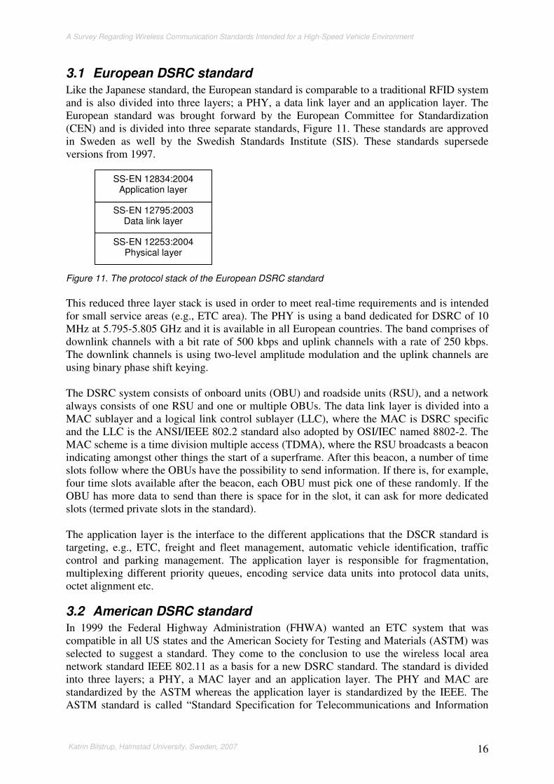
3.1 European DSRC standard Like the Japanese standard, the European standard is comparable to a traditional RFID system and is also divided into three layers; a PHY, a data link layer and an application layer. The European standard was brought forward by the European Committee for Standardization (CEN) and is divided into three separate standards, Figure 11. These standards are approved in Sweden as well by the Swedish Standards Institute (SIS). These standards supersede versions from 1997.
Figure 11. The protocol stack of the European DSRC standard
This reduced three layer stack is used in order to meet real-time requirements and is intended for small service areas (e.g., ETC area). The PHY is using a band dedicated for DSRC of 10 MHz at 5.795-5.805 GHz and it is available in all European countries. The band comprises of downlink channels with a bit rate of 500 kbps and uplink channels with a rate of 250 kbps. The downlink channels is using two-level amplitude modulation and the uplink channels are using binary phase shift keying. The DSRC system consists of onboard units (OBU) and roadside units (RSU), and a network always consists of one RSU and one or multiple OBUs. The data link layer is divided into a MAC sublayer and a logical link control sublayer (LLC), where the MAC is DSRC specific and the LLC is the ANSI/IEEE 802.2 standard also adopted by OSI/IEC named 8802-2. The MAC scheme is a time division multiple access (TDMA), where the RSU broadcasts a beacon indicating amongst other things the start of a superframe. After this beacon, a number of time slots follow where the OBUs have the possibility to send information. If there is, for example, four time slots available after the beacon, each OBU must pick one of these randomly. If the OBU has more data to send than there is space for in the slot, it can ask for more dedicated slots (termed private slots in the standard). The application layer is the interface to the different applications that the DSCR standard is targeting, e.g., ETC, freight and fleet management, automatic vehicle identification, traffic control and parking management. The application layer is responsible for fragmentation, multiplexing different priority queues, encoding service data units into protocol data units, octet alignment etc.
3.2 American DSRC standard In 1999 the Federal Highway Administration (FHWA) wanted an ETC system that was compatible in all US states and the American Society for Testing and Materials (ASTM) was selected to suggest a standard. They come to the conclusion to use the wireless local area network standard IEEE 802.11 as a basis for a new DSRC standard. The standard is divided into three layers; a PHY, a MAC layer and an application layer. The PHY and MAC are standardized by the ASTM whereas the application layer is standardized by the IEEE. The ASTM standard is called “Standard Specification for Telecommunications and Information
SS-EN 12253:2004 Physical layer
SS-EN 12795:2003 Data link layer
SS-EN 12834:2004 Application layer
A Survey Regarding Wireless Communication Standards Intended for a High-Speed Vehicle Environment
Katrin Bilstrup, Halmstad University, Sweden, 2007 17
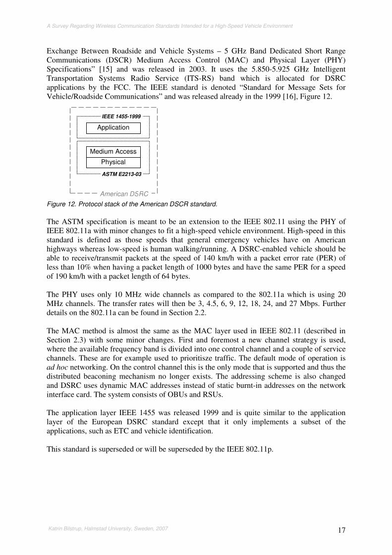
Exchange Between Roadside and Vehicle Systems – 5 GHz Band Dedicated Short Range Communications (DSCR) Medium Access Control (MAC) and Physical Layer (PHY) Specifications” [15] and was released in 2003. It uses the 5.850-5.925 GHz Intelligent Transportation Systems Radio Service (ITS-RS) band which is allocated for DSRC applications by the FCC. The IEEE standard is denoted “Standard for Message Sets for Vehicle/Roadside Communications” and was released already in the 1999 [16], Figure 12.
Figure 12. Protocol stack of the American DSCR standard.
The ASTM specification is meant to be an extension to the IEEE 802.11 using the PHY of IEEE 802.11a with minor changes to fit a high-speed vehicle environment. High-speed in this standard is defined as those speeds that general emergency vehicles have on American highways whereas low-speed is human walking/running. A DSRC-enabled vehicle should be able to receive/transmit packets at the speed of 140 km/h with a packet error rate (PER) of less than 10% when having a packet length of 1000 bytes and have the same PER for a speed of 190 km/h with a packet length of 64 bytes. The PHY uses only 10 MHz wide channels as compared to the 802.11a which is using 20 MHz channels. The transfer rates will then be 3, 4.5, 6, 9, 12, 18, 24, and 27 Mbps. Further details on the 802.11a can be found in Section 2.2. The MAC method is almost the same as the MAC layer used in IEEE 802.11 (described in Section 2.3) with some minor changes. First and foremost a new channel strategy is used, where the available frequency band is divided into one control channel and a couple of service channels. These are for example used to prioritisze traffic. The default mode of operation is ad hoc networking. On the control channel this is the only mode that is supported and thus the distributed beaconing mechanism no longer exists. The addressing scheme is also changed and DSRC uses dynamic MAC addresses instead of static burnt-in addresses on the network interface card. The system consists of OBUs and RSUs. The application layer IEEE 1455 was released 1999 and is quite similar to the application layer of the European DSRC standard except that it only implements a subset of the applications, such as ETC and vehicle identification. This standard is superseded or will be superseded by the IEEE 802.11p.
Application
Medium Access
Physical
ASTM E2213-03
IEEE 1455-1999
American DSRC

A Survey Regarding Wireless Communication Standards Intended for a High-Speed Vehicle Environment
Katrin Bilstrup, Halmstad University, Sweden, 2007 18

A Survey Regarding Wireless Communication Standards Intended for a High-Speed Vehicle Environment
Katrin Bilstrup, Halmstad University, Sweden, 2007 19
4 Wireless broadband networks Broadband networks belong to the group of networks termed metropolitan area networks (MAN) spanning a larger geographic area such as a city. From a historical perspective, a MAN connects local are networks (LANs), which contains end users (i.e., computers). Wireless LANs are usually deployed indoors whereas wireless MANs are used outdoors, having a greater coverage area. There are wireless broadband networks that are intended to be used at a vehicular speed and they are interesting to discuss in this survey since there are already proprietary wireless mobile broadband solutions up and running in several countries. The network topology for wireless broadband networks is cellular containing a base station that controls the medium access within the cell and the handover process will occur seamlessly to the end user. These networks work much in the same way as cellular phone systems, where you as a user pay for a subscription and then get access to the Internet wherever you are (as long as there is coverage). The handheld device or laptop must be equipped with the appropriate network card depending on the technical solution your wireless internet service provider (WISP) is using. The WiMAX standard will also act as a backbone to for example 802.11 hotspots, whereas the IEEE 802.20, WiBRO and the proprietary solutions will connect end users directly. The common denominators of these standards and proprietary solutions are the global addressing scheme, the QoS support, they support handover and roaming and that they are based on the internet protocol (IP), both versions 4 and version 6.
4.1 Standards
4.1.1 IEEE 802.16
The 802.16 family was from the beginning intended for metropolitan area networks (MAN) and the last mile6, but has been extended to include also LANs. In September 2001 the IEEE 802.16 [17] was released, specifying wireless communication in the 10 to 66 GHz range. Two years later this was extended with 802.16a adding additional physical layer specifications to the 2-11 GHz range. In 2006 was a mobile version of this standard called 802.16e released [18], Figure 13. This supports mobile users compared to the origin standard only supporting nomadic users, i.e., a user can move as long as it does not operate while doing so.
Figure 13. An overview of the IEEE 802.16 standards.
6 The wired connection between an Internet service provider and a customer usually owned by a telephone company or a cable television company.
802.16 2001
2002
2003
2004
2005
2006
802.16.2
802.16e
802.16c
802.16a
802.16 802.16.2
802.16f
802.16 = Part 16: Air Interface for Fixed Broadband Wireless Access Systems
802.16.2 = Coexistence of Fixed Broadband Wireless Access Systems
802.16e = Amendment 2: Physical and Medium Access Control Layers for Combined Fixed and Mobile Operation in Licensed Bands
802.16f = Amendment 1: Management Information Base

A Survey Regarding Wireless Communication Standards Intended for a High-Speed Vehicle Environment
Katrin Bilstrup, Halmstad University, Sweden, 2007 20
This family of standards does not target specific frequency bands like the 802.11b for example, but instead it is up to the user (i.e., the WISP) to apply for dedicated bands in their home frequency regulatory domains. The 802.16 standard will both serve as a backbone for 802.11 hotspots as well as connecting end users directly to a cellular network. The IEEE 802.16 standardizes several PHY layers and a MAC layer, Figure 14. The MAC layer consists of three sublayers; the service specific convergence sublayer (CS), MAC common part sublayer (CPS) and the security sublayer. The CS sublayer is a transparent layer to the MAC CPS that hides the differences of higher layer protocols to the CPS. There are two standardized CSs supporting different traffic types. The first CS is defined for asynchronous transfer mode (ATM) (i.e., circuit-switched) and the other is defined for carrying Ethernet and IP traffic (i.e., packet-switched). More CSs can be defined in the future and one MAC CPS can have support for several CSs.
Figure 14. Overview of the protocol suite for IEEE 802.16.
The MAC CPS is responsible for QoS functions, medium access and connection management. The security sublayer is as the name suggests responsible for the security and performs authentication, encryption, decryption and exchange of secure keys. The MAC CPS will support only one specific physical layer in one implementation, but can support more than one CS in the same implementation. The MAC CPS will be tailored to a specific physical layer implementation. There are two different MAC schemes; the mandatory time division multiple access (TDMA) and the optional OFDMA. There are four different physical layers in the standard; three targeting a lower frequency band under 11 GHz and one targeting a high-frequency band between 10-66 GHz, Figure 14. There are two single carriers and two multicarriers, where the multicarriers are based on orthogonal frequency division multiplexing (OFDM). The multicarrier Wireless-OFDM has 256 carriers and the multicarrier Wireless-OFDMA has 2048 carriers. Depending on the physical layer in use there are channel sizes between 1.25-28 MHz and when using a 10 MHz channel can a maximum data rate of 72 Mbps be achieved. The physical channel can use either time division duplex or frequency division duplex. There are two logical entities defined in the standard and these are the base station (BS) and the subscriber station (SS). The BS is more sophisticated than the SS and the standard defines the BS- and SS-specific behaviour in detail. The BS is in charge and the SSs must obey the BS (i.e., master-slave relationship). The network topology is called point-to-multipoint (PMP) and is the same as the infrastructure BSS in the IEEE 802.11 standard. All traffic must go
Service Specific Convergence Sublayer (CS)
WirelessMAN-SC Single Carrier
10-66 GHz Line of Sight
WirelessMAN-SCa Single Carrier
<11 GHz No Line of Sight
WirelessMAN-OFDM Multicarrier <11 GHz
No Line of Sight
WirelessMAN-OFDMA Multicarrier <11 GHz
No Line of Sight
Security Sublayer
Service Specific Convergence Sublayer (CS)
MAC Common Part Sublayer (MAC CPS)
. . . . . . . . . . Medium Access Control
Physical

A Survey Regarding Wireless Communication Standards Intended for a High-Speed Vehicle Environment
Katrin Bilstrup, Halmstad University, Sweden, 2007 21
through the BS and there is no support for ad hoc mode or spontaneous networks. There is however support for multihop through a mesh network topology. This means that a SS in reach for a BS can relay traffic for a SS not in range of the same BS. In Figure 15 SS1 will relay traffic for SS2 since this is out of reach for the BS.
Figure 15. Example of a mesh topology. .
The mobile version 802.16e has support both for handover and roaming at vehicular speeds of up to 120 km/h [19]. The 802.16e allows a base station to support both fixed and mobile users in licensed band below 6 GHz. The physical layers of the lower frequencies are all supported. The physical layer of WirelessMAN-OFDMA was through the 802.16e made scalable and in addition to the 2048 subcarriers also 128, 512 and 1024 subcarriers are supported. There is no support for 256 subcarriers; this is done in order to differentiate Wireless-OFDMA with the Wireless-OFDM physical layer . The 802.16 standard is very comprehensive with a lot of options and for the high-frequency Wireless-SC there is more than 4000 combinations of modulations, FEC etc [20]. Therefore there exist profiles in the standard to give the possibility of interoperability between different vendors.
4.1.2 WiMAX
The world-wide interoperability for microwave access (WiMAX) forum [21] was formed in April 2001 to ensure the interoperability between IEEE 802.16 products. WiMAX is described by the forum as “a standard-based technology enabling the delivery of the last mile wireless broadband access as an alternative to cable and DSL”. The mobile version 802.16e is called Mobile WiMAX. In January 2006 WiMAX started to certify products for the fixed access based on 802.16 in its test lab, situated in Spain [19]. In Korea under supervision of Telecommunication Technology Association (TTA) tests were scheduled to be performed on the Mobile WiMAX products during the last quarter of 2006.
4.1.3 IEEE 802.20
The IEEE 802.20 is still an unapproved standard and this standard is called mobile broadband wireless access (MBWA). The latest draft was approved on January 18th, 2006. This standard is going to specify PHY and MAC layers and it is targeting licensed bands below 3.5 GHz. Vehicular speeds of up to 250 km/h should be supported with user data rates of 1 Mbps downlink and 300 kbps uplink (when using 2!1.25 MHz channels for frequency division duplex and 2.5 MHz channel for time division duplex) [22]. This standard will be used by third parties (i.e., WISPs) that want to offer public access to the Internet much in the same way as the mobile phone operators do.
BS
SS1
SS2
SS3
A Survey Regarding Wireless Communication Standards Intended for a High-Speed Vehicle Environment
Katrin Bilstrup, Halmstad University, Sweden, 2007 22
On June 15, 2006 the work by the IEEE 802.20 working group was suspended until the October 1, 2006. This due to the fact that, according to Intel Corp and Motorola Inc, the chairman of the working group had favoured Qualcomm Inc and Kyocera Inc and threats to file formal complaints were made [23]. There are no clear difference between the IEEE 802.20 and the IEEE 802.16e (Mobile WiMAX).
4.1.4 WiBro
Wireless broadband (WiBro) is a standard developed by the Telecommunication Technology Association (TTA) in South Korea [24]. They are developing this mobile broadband for a dedicated band of 100 MHz at 2.3 GHz. It is using OFDMA and the channel is divided according to time division duplex. The channel width is 10 MHz. The base station will have a coverage radius of 1 km and the subscriber will have rates of up to 50 Mbps at a speed of 120 km/h [25]. The first service that was using WiBro in South Korea was launched June 30, 2006.
4.2 Proprietary solutions
4.2.1 Flash-OFDM
Fast low-latency access with seamless handoff OFDM (flash-OFDM) was developed by Flarion Technologies where Rajiv Laroia led the work that was started already in 2001. Nowadays, Flarion belongs to Qualcomm [26]. Flash-OFDM is implementing a PHY and a data link layer, which is divided into a MAC and logical link control part. The PHY uses a OFDM derivative [27]. When current 3G systems were under development, OFDM was not considered as one of the candidates because of its problem with the peak-to-average power, draining batteries. This problem Flarion claims to have solved [27]. The network of flash-OFDM is cellular, containing a base station named radio router (RR) that regulates the traffic in a work-conserving way. All the mobile stations are allotted a small amount of the available uplink resources and through this they can ask for more resources. This is all that have been found on the MAC method of flash-OFDM since this is a proprietary solution and therefore the details of the MAC method is a trade secret. The transmission uplinks are always unicast whereas the downlinks can be unicast, multicast or broadcast. To achieve high reliability forward error correction (FEC), i.e., low density parity check (LDPC) codes, and automatic repeat request (ARQ) is used. Flash-OFDM can be used in a pure-IP network and can therefore handle IP mobility and security. It also supports QoS by using differentiated services and there is support for handoff in full vehicular mobility. Flash-OFDM works in the same way as other cellular techniques such as GSM and 3G, but in this case there are laptops and handheld computers that will have access to a cellular wide area network. The bit rates are 1-1.5 Mbps uplink with peaks of 3.2 Mbps and 300-500 kbps uplink with peaks of 900 kbps. In Finland the company Digita [28] is using the 450 MHz band that formerly was used by NMT to offer broadband Internet access by using Flash-OFDM. This network called @450 Broadband will be opened April 1, 2007 and will then cover parts of southern Finland and Lapland. The flash-OFDM technique has also been discussed as one possible candidate for the IEEE 802.20 [29].

A Survey Regarding Wireless Communication Standards Intended for a High-Speed Vehicle Environment
Katrin Bilstrup, Halmstad University, Sweden, 2007 23
4.2.2 iBurst
High capacity spatial division multiple access (HC-SDMA) or iBurst is developed by ArrayComm using smart antennas. It is a wireless broadband technology with transfer rates of up to 1 Mbps to end users [30]. iBurst is thought of being the new IEEE 802.20 mobile broadband wireless access network standard according to Kyocera Inc [31]. iBurst is already up, running in several countries; Australia, South Africa, Norway, Canada etc., providing Internet access to subscribers.

A Survey Regarding Wireless Communication Standards Intended for a High-Speed Vehicle Environment
Katrin Bilstrup, Halmstad University, Sweden, 2007 24

A Survey Regarding Wireless Communication Standards Intended for a High-Speed Vehicle Environment
Katrin Bilstrup, Halmstad University, Sweden, 2007 25
5 CALM Communication/continuous air-interface long and medium range (CALM) is a framework under development of ISO TC 204 WG 16 and the idea was born as a concept in 2000. In Appendix D more information on the ISO work can be found. CALM is intended to be used in packet-switched networks in mobile environments using different carriers, e.g., 2G, 3G, WiMAX, based on the internet protocol version 6 (IPv6). This framework does not only intend to include already existing standards but also standards under development, e.g., 802.20 and 802.11p. The handover procedure is not developed by CALM, which instead relies on IPv6 for vertical handovers and on medium-specific for horizontal handover [32]. A vertical handover takes place between two different wireless communication systems, e.g., a handoff between 3G and 802.11, whereas a horizontal handover is between cells using the same technique. CALM defines five communication scenarios summarized in Table 3. Table 3. Summarizing the different communications scenarios defined by CALM.
1 Non-IPv6 Vehicle-to-infrastructure
2 Local IPv6 Vehicle-to-vehicle Vehicle-to-infrastructure
3 Mobile IPv6 Vehicle-to-infrastructure
4 Network mobility (NEMO) Vehicle-to-infrastructure
5 Non-IPv6 Vehicle-to-vehicle
CALM M5 is thought to incorporate the WAVE profile (i.e., IEEE 802.11p) and also adds for example 2G/3G network interconnectivity, DSRC, European 5 GHz spectrum [32].

A Survey Regarding Wireless Communication Standards Intended for a High-Speed Vehicle Environment
Katrin Bilstrup, Halmstad University, Sweden, 2007 26

A Survey Regarding Wireless Communication Standards Intended for a High-Speed Vehicle Environment
Katrin Bilstrup, Halmstad University, Sweden, 2007 27
6 IEEE 802.21 In 2003 the discussion within IEEE started about developing a standard for media independent handover across 802 networks [33] and cellular systems such as 2G and 3G. This standard which is in its draft stage is called 802.21. In Figure 16 vertical handovers between different network types within 802 are illustrated.
Figure 16. Vertical handovers within the 802 family.
Figure 17 shows where the 802.21 protocol is found in the protocol suite.
Figure 17. Shows where the IEEE 802.21 protocol is situated.
Internet
802.3 Ethernet 802.11 WLAN 802.16 WMAN
Sitting at desktop Walking around indoor
Walking around outdoor
Handoff Handoff
Physical layer
Medium access control
Logical link control
IEEE 802.21 Handover
Network layer
Data link layer

A Survey Regarding Wireless Communication Standards Intended for a High-Speed Vehicle Environment
Katrin Bilstrup, Halmstad University, Sweden, 2007 28

A Survey Regarding Wireless Communication Standards Intended for a High-Speed Vehicle Environment
Katrin Bilstrup, Halmstad University, Sweden, 2007 29
7 Discussion The name DSRC refers to a plethora of applications and standards developed in different parts of the world, e.g., Japan, North America, Korea, Europe, and Brazil. Some of the standards are pure RFID-look-a-like systems whereas the American standard is directly derived from the WLAN standard 802.11. These DSRC systems all have different ability to support real-time traffic (i.e., QoS). The RFID-look-a-like DSRC standards typically use a master-slave scheme as the medium access method and this inherently supports real-time access since the master is either polling or scheduling time slots for the mobile stations, making it deterministic, but also introducing an increased delay since all communication goes through the master. Further, there is no V2V communication and no handover. These systems are intended for stand-alone applications such as a toll collection area or parking management. The DSRC standard of North America was developed by ASTM and it uses IEEE 802.11 with some minor changes to fit a high-speed vehicle environment. However, since the ASTM standard does not support QoS traffic, a new amendment, IEEE 802.11p, is under way and the work with the DSRC standard has been taken over by IEEE. IEEE 802.11p uses EDCA as medium access scheme, derived from the IEEE 802.11e, and aims at providing QoS in terms of increased probability of timely channel access for delay sensitive traffic. The basic access technique still uses the CSMA/CA and the mobile stations only prioritize their own traffic and thus collisions between mobile stations can occur (and theoretically reoccur forever). The IEEE 802.11p together with the IEEE standards 1609.1, 1609.2, 1609.3 and 1609.4 forms the WAVE protocol stack. The association and authentication procedures are removed from WAVE as compared to an ordinary WLAN environment to reduce the average delay. The WAVE protocol stack also incorporates a TCP/IP part in order to provide Internet access. In 1609.4 a new channel strategy is presented where one control channel is used together with a couple of service channels. On the control channel only short urgent WAVE messages are allowed and the TCP/IP traffic is instead directed to the service channels. This separation increases the probability that urgent messages will reach the intended recipients on time. There will however be a problem when a lot of mobile stations want to alert other drivers about upcoming dangerous situations. From a physical and data link layer perspective all nodes look the same in a WAVE system. There is no central access point as in the usual WLAN environment, but from the application view point there is a difference between the onboard units and roadside units. Further, the WAVE communication stack does not have multihop support nor does it support handover. The TCP/IP part supports only IPv6 (not IPv4) enabling handovers to take place among the service channels by using the upcoming Internet standard RFC 4068 called Fast handovers for Mobile IPv6. This is, however, still in its draft stage. The need for handover in the WAVE part of the stack is not crucial since the communication will be local and thus most likely be finished before a vehicle will be out of reach from the roadside unit in question. All wireless standards that will use IPv6 will probably have support for fast handovers in the future. For the moment there are no countries outside the US that have allocated a 75 MHz band for ITS applications. This implies that the IEEE 802.11p standard, designed for a specific frequency band, cannot be used right away outside the US. The wireless broadband standards, e.g., 802.16, 802.20 and WiBro, typically have deterministic access schemes, but they are using a base station or an access point to achieve this, implying two things. First and foremost more average delay is introduced into the system since communication directly between two moving vehicles is no longer possible. Secondly, the vehicle must be in range of a base station and this is not always the case. There are alert situations where it is interesting and sometimes necessary to have communication between

A Survey Regarding Wireless Communication Standards Intended for a High-Speed Vehicle Environment
Katrin Bilstrup, Halmstad University, Sweden, 2007 30
vehicles directly and more spontaneously, in an ad hoc fashion. An example of this is when an accident occurs where there are no base stations or other infrastructure present. The wireless broadband standards are suitable for Internet access and especially so when considering delay sensitive traffic such as IP telephony and video streaming. Some proprietary mobile broadband wireless access networks are already up and running, e.g., iBurst and flash-OFDM. These are considered when designing the new mobile broadband networking standard IEEE 802.20. The already existing IEEE 802.16 has, however, a head start since the IEEE 802.20 is only in the draft stage. Common denominators of these standards are that they all support QoS, handover and roaming at vehicle speed. PTS, the national frequency allocation organ of Sweden, will during the autumn of 2007 provide an auction through which interested can be allotted a frequency band between 3.6-3.8 GHz. These bands will be used for mobile broadband access systems such as WiMax (i.e., IEEE 802.16). CALM differs from the other standards discussed here since the framework CALM will make use of already existing as well as upcoming standards (standards that currently are in their draft stages). It can therefore be concluded from the above discussion that since none of the upcoming standards has the ability of supporting real-time in the V2V case neither will CALM.

A Survey Regarding Wireless Communication Standards Intended for a High-Speed Vehicle Environment
Katrin Bilstrup, Halmstad University, Sweden, 2007 31
8 Conclusion One of the most important properties of a wireless vehicle alert system is the media access scheme, determining who transmits when on the unpredictable wireless channel. The MAC scheme must provide some sort of finite worst case access time to guarantee that communication tasks meet their deadline. Once the channel access is a fact, different channel coding strategies combined with diversity techniques can be used to achieve a more reliable transmission. Coding and diversity can be used to overcome difficulties with e.g., multipath and also to efficiently use the scarce allotted frequency spectrum. With a robust coding and diversity scheme, the number of retransmissions can be reduced with a decreased delay as a result. In the vehicle-to-infrastructure communication case, a deterministic media access scheme is more easily deployed since there is a centralized base station or access point that can control the media access. Such a centralized mechanism is hard to achieve in a distributed vehicle-to-vehicle network where all nodes are highly mobile. The procedure of determining a master in a vehicular ad hoc network (VANET) would incur too much delay and when the decision finally was made, the network topology will most likely already have changed due to the high mobility of the node in the system. In the VAS project both vehicle-to-vehicle as well as vehicle-to-infrastructure communication are used and since the project is aiming for real-time communication, there is a need for a deterministic access in both cases. We can conclude that here are no standards that completely fit the VAS project. Within vehicle alert systems such as VAS there is a need for using both vehicle-to-vehicle and vehicle-to-infrastructure communication with strict real-time requirements. The mobile broadband standards, having deterministic MAC methods together with QoS support, cannot be used in ad hoc mode (vehicle-to-vehicle) but could with advantage be used for other types of data traffic (e.g. Internet access). The IEEE 802.11p standard together with the WAVE protocol stack could be used for ad hoc vehicle-to-vehicle communication, but since the MAC does not have an upper bound on when access to the channel occurs; it is unsuitable for delay sensitive alert systems requiring a high QoS. The different DSRC standards, intended for simpler applications such as electronic toll collection, parking management etc., do not support vehicle-to-vehicle communication since the MAC is based on a master-slave polling scheme where the master is more sophisticated than the slave. Finally, the DSRC standards and the mobile broadband standards have rather modest transfer rates of up to 1 Mbps, although the latter will be improved in the near future. The WAVE stack supports rates from 3 up to 27 Mbps. Even though a higher transfer rate does not give any guarantees of upper bounded maximum delays, it may help reduce the probability of large delays actually to occur.

A Survey Regarding Wireless Communication Standards Intended for a High-Speed Vehicle Environment
Katrin Bilstrup, Halmstad University, Sweden, 2007 32
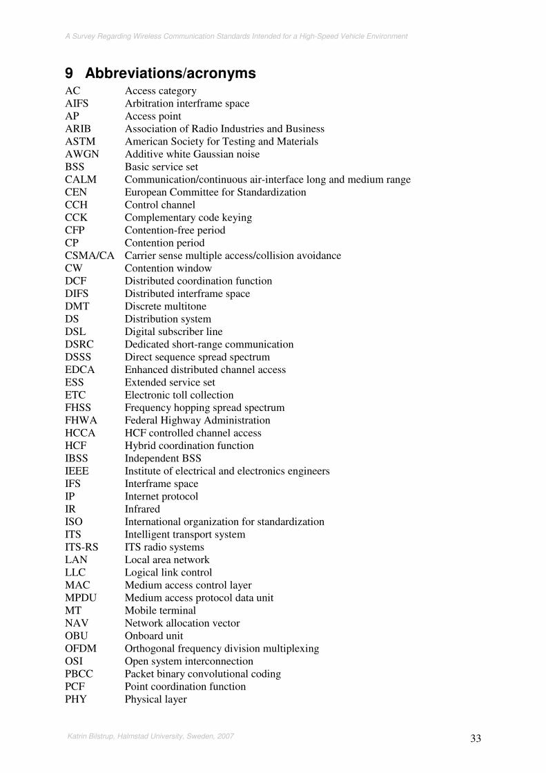
A Survey Regarding Wireless Communication Standards Intended for a High-Speed Vehicle Environment
Katrin Bilstrup, Halmstad University, Sweden, 2007 33
9 Abbreviations/acronyms AC Access category AIFS Arbitration interframe space AP Access point ARIB Association of Radio Industries and Business ASTM American Society for Testing and Materials AWGN Additive white Gaussian noise BSS Basic service set CALM Communication/continuous air-interface long and medium range CEN European Committee for Standardization CCH Control channel CCK Complementary code keying CFP Contention-free period CP Contention period CSMA/CA Carrier sense multiple access/collision avoidance CW Contention window DCF Distributed coordination function DIFS Distributed interframe space DMT Discrete multitone DS Distribution system DSL Digital subscriber line DSRC Dedicated short-range communication DSSS Direct sequence spread spectrum EDCA Enhanced distributed channel access ESS Extended service set ETC Electronic toll collection FHSS Frequency hopping spread spectrum FHWA Federal Highway Administration HCCA HCF controlled channel access HCF Hybrid coordination function IBSS Independent BSS IEEE Institute of electrical and electronics engineers IFS Interframe space IP Internet protocol IR Infrared ISO International organization for standardization ITS Intelligent transport system ITS-RS ITS radio systems LAN Local area network LLC Logical link control MAC Medium access control layer MPDU Medium access protocol data unit MT Mobile terminal NAV Network allocation vector OBU Onboard unit OFDM Orthogonal frequency division multiplexing OSI Open system interconnection PBCC Packet binary convolutional coding PCF Point coordination function PHY Physical layer

A Survey Regarding Wireless Communication Standards Intended for a High-Speed Vehicle Environment
Katrin Bilstrup, Halmstad University, Sweden, 2007 34
PIFS PCF IFS QoS Quality of service RCP Resource command processor RFID Radio frequency identification RM Resource manager RMA RM application RSU Roadside unit SCH Service channel SIFS Short interframe space SIG Special interest group SIS Swedish Standards Institute TC Technical committee TCP Transmission control protocol TG Task group TTA Telecommunication Technology Association UDP User datagram protocol UP User priority UTC Coordinated universal time WAVE Wireless access in vehicular environments WBSS WAVE basic service set WG Working group WSA WAVE service advertisement WSMP WAVE short message protocol WLAN Wireless local area network

A Survey Regarding Wireless Communication Standards Intended for a High-Speed Vehicle Environment
Katrin Bilstrup, Halmstad University, Sweden, 2007 35
10 References [1] IEEE Std. 802.11, Part 11: Wireless LAN Medium Access Control (MAC) and
Physical Layer (PHY) Specifications, 1999. [2] http://www.wi-fi.org/, September 2006. [3] IEEE Std. 802.11e-2005, Part 11: Wireless LAN Medium Access Control (MAC)
and Physical Layer (PHY) Specifications: Amendment 8: Medium Access Control (MAC) Quality of Service Enhancements, 2005.
[4] J. Heiskala and J. Terry, OFDM Wireless LANs: A Theoretical and Practical
Guide, Sams Publishing, US, 2002. [5] IEEE Std. 802.11a-1999, Part 11: Wireless LAN Medium Access Control (MAC)
and Physical Layer (PHY) Specifications: High-Speed Physical Layer in the 5 GHz Band, 1999.
[6] IEEE Std. 802.1D-2004, Media Access Control (MAC) Bridges, 2004. [7] IEEE P802.11p/D1.4, Part 11: Wireless LAN Medium Access Control (MAC)
and Physical Layer (PHY) Specifications: Amendment: Wireless Access in Vehicular Environments (WAVE), Draft 1.4, November 2006.
[8] IEEE Std. 1609.1-2006, IEEE Trial-Use Standard for Wireless Access in
Vehicular Environments (WAVE) – Resource Manager, 2006. [9] IEEE P1609.3/D19, Wireless Access in Vehicular Environments (WAVE) –
Networking Services, Draft 19, March 2006. [10] IEEE Std. 1609.2-2006, IEEE Trial-Use Standard for Wireless Access in
Vehicular Environments (WAVE) – Security Services for Applications and Management Messages, 2006.
[11] IEEE Std. 1609.4-2006, IEEE Trial-Use Standard for Wireless Access in
Vehicular Environments (WAVE) – Multi-channel operation, 2006. [12] K. Finkenzeller, RFID Handbook, John Wiley & Sons, New York, US, 1999. [13] R. Schnacke, “Automative RFID gets rolling”,
http://www.rfidjournal.com/article/articleview/866/1/1/ November 2006. [14] http://www.arib.or.jp, December 2006. [15] ASTM E2213-03, Standard Specification for Telecommunications and
Information Exchange Between Roadside and Vehicle Systems – 5 GHz Band Dedicated Short Range Communications (DSCR) Medium Access Control (MAC) and Physical Layer (PHY) Specifications, 2003.

A Survey Regarding Wireless Communication Standards Intended for a High-Speed Vehicle Environment
Katrin Bilstrup, Halmstad University, Sweden, 2007 36
[16] IEEE Std. 1455-1999, IEEE Standard for Message Sets for Vehicle/Roadside Communications, 1999.
[17] IEEE Std. 802.16-2004, Part 16: Air Interface for Fixed Broadband Wireless
Access Systems, 2004. [18] IEEE Std. 802.16e-2004, Part 16: Air Interface for Fixed Broadband Wireless
Access Systems: Amendment 2: Physical and Medium Access Control Layers for Combined Fixed and Mobile Operation in Licensed Band and Corrigendum 1, 2006.
[19] Z. Abichar, Y. Peng, and J. Morris Chang, “WiMAX: The emergence of
wireless broadband,” IEEE IT Professional, vol. 8, no. 4, pp. 44-48, July-August 2006.
[20] C. Eklund et al., WirelessMAN Inside the IEEE 802.16TM Standard for Wireless
Metropolitan Area Network, IEEE Press, New York, US, 2006. [21] http://www.wimaxforum.org/, December 2006. [22] http://www.ieee802.org/20/index.html, December 2006. [23] http://www.eetimes.com/news/latest/showArticle.jhtml?articleID=189401737,
December 2006. [24] http://www.wibro.or.kr, December 2006. [25] http://www.eetimes.com/news/latest/showArticle.jhtml?articleID=189800030,
December 2006. [26] www.qualcomm.com/qft, December 2006. [27] M. Scott Corson et al., “A new paradigm for IP-based cellular networks,” IEEE
IT Professional, vol. 3, no. 6, pp. 20-29, November-December 2001. [28] www.digita.fi, December 2006. [29] S. Tsumuru, R. Mino, S. Hara, and Y. Hara, ”Performance comparison of
OFDM-FH and MC-CDM in single and multi-cell environments,” in Proc. of the IEEE Vehicular Technology Conference, Stockholm, Sweden, May 2005, pp. 1730-1734.
[30] http://en.wikipedia.org/wiki/IBurst, December 2006. [31] http://global.kyocera.com/, December 2006. [32] http://grouper.ieee.org/groups/802/11/Reports/tgp_update.htm, December 2006. [33] http://www.ieee802.org/21/, February 2007.
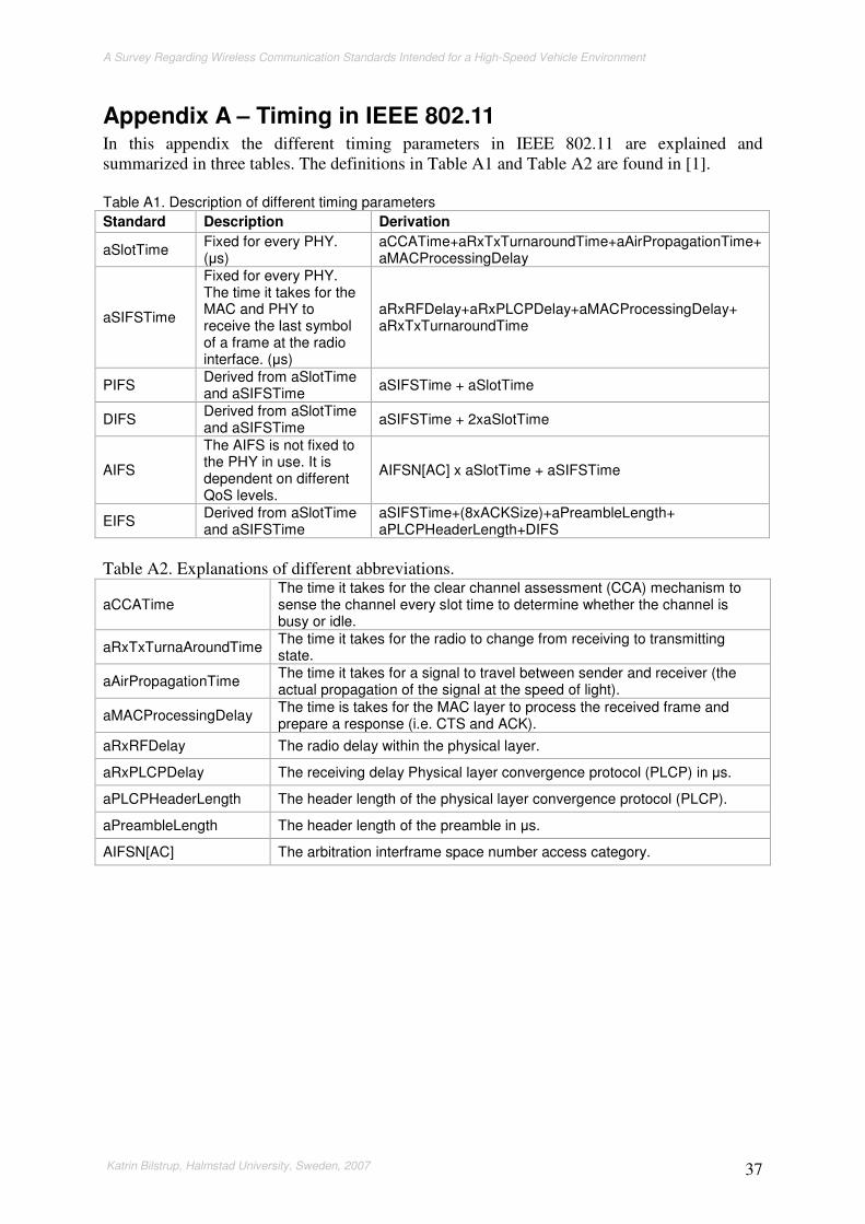
A Survey Regarding Wireless Communication Standards Intended for a High-Speed Vehicle Environment
Katrin Bilstrup, Halmstad University, Sweden, 2007 37
Appendix A – Timing in IEEE 802.11 In this appendix the different timing parameters in IEEE 802.11 are explained and summarized in three tables. The definitions in Table A1 and Table A2 are found in [1]. Table A1. Description of different timing parameters
Standard Description Derivation
aSlotTime Fixed for every PHY. (s)
aCCATime+aRxTxTurnaroundTime+aAirPropagationTime+ aMACProcessingDelay
aSIFSTime
Fixed for every PHY. The time it takes for the MAC and PHY to receive the last symbol of a frame at the radio interface. (s)
aRxRFDelay+aRxPLCPDelay+aMACProcessingDelay+ aRxTxTurnaroundTime
PIFS Derived from aSlotTime and aSIFSTime
aSIFSTime + aSlotTime
DIFS Derived from aSlotTime and aSIFSTime
aSIFSTime + 2xaSlotTime
AIFS
The AIFS is not fixed to the PHY in use. It is dependent on different QoS levels.
AIFSN[AC] x aSlotTime + aSIFSTime
EIFS Derived from aSlotTime and aSIFSTime
aSIFSTime+(8xACKSize)+aPreambleLength+ aPLCPHeaderLength+DIFS
Table A2. Explanations of different abbreviations.
aCCATime The time it takes for the clear channel assessment (CCA) mechanism to sense the channel every slot time to determine whether the channel is busy or idle.
aRxTxTurnaAroundTime The time it takes for the radio to change from receiving to transmitting state.
aAirPropagationTime The time it takes for a signal to travel between sender and receiver (the actual propagation of the signal at the speed of light).
aMACProcessingDelay The time is takes for the MAC layer to process the received frame and prepare a response (i.e. CTS and ACK).
aRxRFDelay The radio delay within the physical layer.
aRxPLCPDelay The receiving delay Physical layer convergence protocol (PLCP) in s.
aPLCPHeaderLength The header length of the physical layer convergence protocol (PLCP).
aPreambleLength The header length of the preamble in s.
AIFSN[AC] The arbitration interframe space number access category.

A Survey Regarding Wireless Communication Standards Intended for a High-Speed Vehicle Environment
Katrin Bilstrup, Halmstad University, Sweden, 2007 38
Table A3. Shows the actual times for different physical layers.
Physical layer
aSlotTime [s]
aSIFSTime [s]
DIFS [s] PIFS [s] CWmin CWmax
DSSS (Section 15.3.3 [dot11])
20 10 40 30 31 1023
FHSS (Section 14.9 [dot11])
50 28 106 78 15 1023
IR (Section 16.4 [dot11])
8 10 28 18 63 1023
DSSS/HR (section 18.3.4 [dot11b])
20 10 40 30 31 1023
OFDM (section 17.5.2 [dot11a])
9 16 41 25 15 1023
[DSSS/CCK]/ OFDM/ PBCC /DSSS-OFDM (section 19.8.4 [dot11g])
Short = 9 Long = 20
10
28 short 50 long
19 short 30 long
Dependent of special
characteristics of the rate set
Dependent of special
characteristics of the rate set

A Survey Regarding Wireless Communication Standards Intended for a High-Speed Vehicle Environment
Katrin Bilstrup, Halmstad University, Sweden, 2007 39
Appendix B – IEEE 802.11 amendments and supplements This appendix contains a table providing an overview to the different supplements and amendments to the legacy 802.11 standard. Table B1. Overview of the IEEE 802.11 alphabet soup.
Amendment A=approved U=unapproved W=withdrawn
Description
802.11 A Legacy 802.11 standard containing three different physical layers.
802.11a A Physical layer supplement using the 5 GHz band.
802.11b A Physical layer supplement using the 2.4 GHz band.
802.11c A Concerning bridge operations and is included in the IEEE 802.1D.
802.11d A Concerning roaming extensions (country-to-country).
802.11e A QoS enhancement to the MAC layer.
802.11F W Was a stand-alone document about inter-access point protocol.
802.11g A Physical layer amendment using the 2.4 GHz band.
802.11h A Spectrum management of the 5GHz band of Europe.
802.11i A Enhanced security.
802.11j A 4.9-5.0 GHz operation in Japan.
802.11k U Radio resource measurements.
802.11m Maintenance of the standard.
802.11n U (April 2008) Higher throughput. 2.4 GHz or 5 GHz. Will use multiple antennas for receiving and transmitting data (MIMO).
802.11p U Extension to the 802.11 both at PHY and MAC level to support high mobility.
802.11r U (End of 2006) Fast roaming.
802.11s U (during 2008) WLAN mesh networking.
802.11T U (Jan 2008) Stand-alone document about testing WLAN equipment.
802.11u U Specifying inter-networking with other type of networks, e.g., UMTS.
802.11v U Network management.
802.11w U Extension to 802.11i, enhancing the security even further.
802.11y U 3.65-3.7 GHz operation in the US.

A Survey Regarding Wireless Communication Standards Intended for a High-Speed Vehicle Environment
Katrin Bilstrup, Halmstad University, Sweden, 2007 40

A Survey Regarding Wireless Communication Standards Intended for a High-Speed Vehicle Environment
Katrin Bilstrup, Halmstad University, Sweden, 2007 41
Appendix C – Clause overview IEEE 802.11 In Table C1 is a crib shown over the different clauses of 802.11 that interfere with different extensions and amendments. The legacy 802.11 standard contained 16 clauses where the extension 802.11a adds one clause and extend one, whereas the quality of service standard 802.11e makes changes to clause 1-11 of the legacy standard but does not add any new clauses. In Table C2 the different clause names are shown. Table C1. A crib to show the different clauses of the 802.11 suite. 1 2 3 4 5 6 7 8 9 10 11 12 13 14 15 16 17 18 19 20 21 22
802.11 x x x x x x x x x x x x x x x x
802.11a x x
802.11b x x x x x
802.11e x x x x x x x x x x x
802.11g x x x x x x x
802.11p x x x x x x x x x
Table C2. Clause names
Clause Name
1 Overview 2 Normative references 3 Definitions 4 Abbreviations and acronyms 5 General description 6 MAC service definition 7 Frame formats 8 Authentication and privacy 9 MAC sublayer functional description 10 Layer management 11 MAC sublayer management entity 12 Physical layer (PHY) service specification 13 PHY management 14 FHSS PHY specification for the 2.4 GHz 15 DSSS PHY specification for the 2.4 GHz 16 Infrared PHY specification 17 OFDM PHY specification for the 5 GHz 18 HR/DSSS PHY specification 19 Extended Rate PHY specification 20 WAVE PHY specification

A Survey Regarding Wireless Communication Standards Intended for a High-Speed Vehicle Environment
Katrin Bilstrup, Halmstad University, Sweden, 2007 42

A Survey Regarding Wireless Communication Standards Intended for a High-Speed Vehicle Environment
Katrin Bilstrup, Halmstad University, Sweden, 2007 43
Appendix D – Standard bodies around the world
CEN CEN stands for European Committee for Standardization and CEN as an abbreviation is derived from the French language, i.e., Comité Européen de Normalisation. CEN has a technical committee named TC278 which special interest is road transport and traffic telematics (and this is also their name). TC278 is further divided into 15 working groups, see Table D1. Table D1. An overview of the technical committee 278 and its working groups
WG CEN TC 278 RTTT
1 Electronic fee collection and access control (EFC)
2 Freight and Fleet Management systems (FFMS)
3 Public Transport (PT)
4 Traffic and Travel Information (TTI)
5 Traffic Control (TC)
6 Parking Management (PM)
7 Geographic Road Data (GRD)
8 Road traffic data (RTD)
9 Dedicated Short Range Communication (DSRC)
10 Man-Machine Interface
11 Subsystem/Intersystem Interfaces
12 Automatic Vehicle Identification (AVI) and Automatic Equipment Identifiication (AEI)
13 Architecture and Terminology
14 After-theft Systems and Vehicle Recovery
15 eSafety
CEN TC278 WG9 is responsible for the DSRC standard developed in Europe named
• EN 12253:2004 Road transport and traffic telematics – Dedicated short-range communication – Physical layer using microwave at 5,8 GHz
• EN 12795 Road transport and traffic telematics – Dedicated short-range communication (DSCR) – DSRC data link layer: medium access and logical link control
• EN 12834 Road transport and traffic telematics – Dedicated short-range communication (DSCR) – DSRC application layer
• EN 13372:2004 Road transport and traffic telematics – Dedicated short-range communication – Profiles for RTTT applications
These standards are approved in Sweden by the Swedish standards institute and are renamed with SS in front of the EN name, i.e., SS- EN 12253:2004, SS- EN 12795, SS- EN 12834, and SS- EN 13372:2004.

A Survey Regarding Wireless Communication Standards Intended for a High-Speed Vehicle Environment
Katrin Bilstrup, Halmstad University, Sweden, 2007 44
ETSI European Telecommunications Standards Institute (ETSI) was founded 1988 on the European Commissions’ initiative and it is not a part of CEPT. It is developing standards within the following areas: telecommunications, radio communications, broadcasting and related topics. ETSI provides tools to assist in certification of products and coordinates and contributes to frequency allocation matters. ETSI has developed a European Standard concerning type approval and conformance testing of DSRC equipment. This is divided into two parts:
• ETSI EN 300 674-1 Electromagnetic compatibility and radio spectrum matters (ERM); Road transport and traffic telematics (RTTT); Dedicated Short-range communication (DSRC) transmission equipment (500 kbps and / 250 kbps) operating in the 5,8 GHz Industrial and Scientific and Medical (ISM) band; Part 1: General characteristics and test methods for Road Side Units (RSU) and On-Board Units (OBU)
• ETSI EN 300 674-2-2 Electromagnetic compatibility and radio spectrum matters (ERM); Road transport and traffic telematics (RTTT); Dedicated Short-range communication (DSRC) transmission equipment (500 kbps and / 250 kbps) operating in the 5,8 GHz Industrial and Scientific and Medical (ISM) band; Part 2: Harmonized EN under article 3.2 of the R&TTE directive; Sub-part 2: Requirements for the On-Board Units (OBU)
The activities that are related to intelligent transport systems (ITS) within ETSI are collected in a task group called TG 37. This task group works in close cooperation with CEN TC 278 and ISO TC 204. The ETSI TG 37 will have a look at spectrum matters of the 5-6 GHz in Europe, cellular convergence standards and testing/formal protocol verification.

A Survey Regarding Wireless Communication Standards Intended for a High-Speed Vehicle Environment
Katrin Bilstrup, Halmstad University, Sweden, 2007 45
ISO International Organization for Standardization (ISO) is situated in Geneva Switzerland and coordinates a network of national standards institutes from 157 countries. It consists of 229 different technical committees where TC 204 is intelligent transport systems (ITS). The TC 204 is further divided into 12 work groups, see Table D2. Table D2. The technical committee 204 and its working groups.
WG ISO TC 204 ITS
1 Architecture
3 Transport information and control systems (TICS) database technology
4 Automatic vehicle and equipment identification
5 Fee and toll collection
7 General fleet management and commercial/freight
8 Public transport/emergency
9 Integrated transport information, management and control
10 Traveller information system
11 Route guidance and navigation system
14 Vehicle/roadway warning and control system
15 Dedicated short-range communications for TICS application
16 Wide area communications/protocols and interfaces
The WG 16 is working on the CALM standard and WG 15 is for the moment working on a standard of a DSRC application layer (ISO 15628). ISO is also working on a DSRC application layer which is called ISO 15628 Road transport and traffic telematics – Dedicated short range communications (DSRC) – DSRC application layer. This is under development by TC204/WG15 (DSRC, CEN WG9) and is in the publication stage (60.00). It is similar to the application layer of CEN, Section 3.1, with some minor changes.


![Justin Thiel [justin@binaryllama.net]jain/cse574-06/ftp/wimax.pdf3. 802.20: Mobile Broadband Wireless Access ... The IEEE 802.20 working group, ... The original intention of the group](https://static.fdocuments.in/doc/165x107/5b2f8e237f8b9a594c8e633f/justin-thiel-justin-jaincse574-06ftpwimaxpdf3-80220-mobile-broadband.jpg)