
A SURVEY OF TECHNOLOGY FOR HYBRID VEHICLE AUXILIARY … · A Survey of Technology for Hybrid...
91
AD A SURVEY OF TECHNOLOGY FOR HYBRID VEHICLE AUXILIARY POWER UNITS INTERIM REPORT TFLRF No. 311 By S.K. Widener Southwest Research Institute San Antonio, Texas li u Prepared for Advanced Research Projects Agency 3701 N. Fairfax Drive Arlington, Virginia 22203-1714 Under Contract to U.S. Army TARDEC Mobility Technology Center-Belvoir Fort Belvoir, Virginia Contract No. DAAK70-92-C-0059 Approved for public release; distribution unlimited October 1995 NOV
Transcript of A SURVEY OF TECHNOLOGY FOR HYBRID VEHICLE AUXILIARY … · A Survey of Technology for Hybrid...
AD
A SURVEY OF TECHNOLOGY FOR HYBRID VEHICLE
AUXILIARY POWER UNITS
INTERIM REPORT TFLRF No. 311
By
S.K. Widener Southwest Research Institute
San Antonio, Texas
li u
Prepared for
Advanced Research Projects Agency 3701 N. Fairfax Drive
Arlington, Virginia 22203-1714
Under Contract to
U.S. Army TARDEC Mobility Technology Center-Belvoir
Fort Belvoir, Virginia
Contract No. DAAK70-92-C-0059
Approved for public release; distribution unlimited
October 1995
NOV

Disclaimers
The findings in this report are not to be construed as an official Department of the Army position unless so designated by other authorized documents.
Trade names cited in this report do not constitute an official endorsement or approval of the use of such commercial hardware or software.
DTiC Availability Notice
Qualified requestors may obtain copies of this report from the Defense Technical Information Center, Cameron Station, Alexandria, Virginia 22314.
Destroy this report when no longer needed. Do not return it to the originator.
REPORT DOCUMENTATION PAGE Form Approved OMB No. 0704-0188
Public reporting burden for this collection of information is estimated to average 1 hour per response, including the time for reviewing instruction, searching existing data sources, gathering and maintaining the data needed, and completing and reviewing the collection of information. Send comments regarding this burden estimate or any other aspect of this collection of information, including suggestions for reducing this burden, to Washington Headquarters Services, Directorate for Information Operations and Reports, 1215 Jefferson Davis Highway, Suite 1204, Arlington. VA 22202-4302, and to the Office of Management and Budget, Paperwork Reduction Project (0704-0188), Washington, DC 20503.
1. AGENCY USE ONLY (Leave blank) 2. REPORT DATE
October 1995
3. REPORT TYPE AND DATES COVERED
Interim April 1994 to June 1995
4. TITLE AND SUBTITLE
A Survey of Technology for Hybrid Vehicle Auxiliary Power Units
6. AUTHOR(S)
Widener, Stanley K.
5. FUNDING NUMBERS
DAAK70-92-C-0059; WD 20 & 36
7. PERFORMING ORGANIZATION NAME(S) AND ADDRESS(ES)
Southwest Research Institute P.O. Drawer 28510 San Antonio, Texas 78228-0510
8. PERFORMING ORGANIZATION REPORT NUMBER
TFLRFNo. 311
9. SPONSORING/MONITORING AGENCY NAME(S) AND ADDRESS(ES) 10. SPONSORING/MONITORING AGENCY REPORT NUMBER
Department of the Army Mobility Technology Center-Belvoir 10115 Gridley Road, Suite 128 Ft. Belvoir, Virginia 22060-5843
Advanced Research Projects Agency 3701 N. Fairfax Drive Arlington, Virginia 22203-1714
11. SUPPLEMENTARY NOTES
12a. DISTRIBUTION/AVAILABILITY STATEMENT
Approved for public release; distribution unlimited
12b. DISTRIBUTION CODE
13. ABSTRACT (Maximum 200 words)
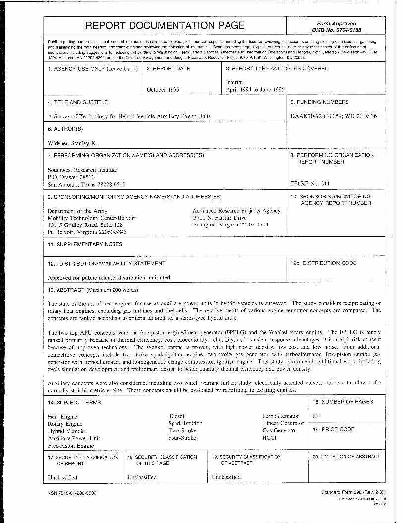
The state-of-the-art of heat engines for use as auxiliary power units in hybrid vehicles is surveyed. The study considers reciprocating or rotary heat engines, excluding gas turbines and fuel cells. The relative merits of various engine-generator concepts are compared. The concepts are ranked according to criteria tailored for a series-type hybrid drive.
The two top APU concepts were the free-piston engine/linear generator (FPELG) and the Wankel rotary engine. The FPELG is highly ranked primarily because of thermal efficiency, cost, producibility, reliability, and transient response advantages; it is a high risk concept because of unproven technology. The Wankel engine is proven, with high power density, low cost and low noise. Four additional competitive concepts include two-stroke spark-ignition engine, two-stroke gas generator with turboalternator, free-piston engine gas generator with turboalternator, and homogeneous charge compression ignition engine. This study recommends additional work, including cycle simulation development and preliminary design to better quantify thermal efficiency and power density.
Auxiliary concepts were also considered, including two which warrant further study: electrically actuated valves, and lean turndown of a normally stoichiometric engine. These concepts should be evaluated by retrofitting to existing engines.
14. SUBJECT TERMS
Heat Engine Rotary Engine Hybrid Vehicle Auxiliary Power Unit Free-Piston Engine
Diesel Spark-Ignition Two-Stroke Four-Stroke
Turboalternator Linear Generator Gas Generator HCCI
15. NUMBER OF PAGES
16. PRICE CODE
17. SECURITY CLASSIFICATION OF REPORT
Unclassified
18. SECURITY CLASSIFICATION OF THIS PAGE
Unclassified
19. SECURITY CLASSIFICATION OF ABSTRACT
Unclassified
20. LIMITATION OF ABSTRACT
NSN 7540-01-280-5500 Standard Form 298 (Rev. 2-89) Prescribed by ANSI Std. 239-18
29B-102

EXECUTIVE SUMMARY
Problems: This study was undertaken to survey the state-of-the-art of heat engines for use as power plants in hybrid vehicles. It assumes that the heat engine drives an electric generator providing auxiliary power for charging batteries and/or powering the electric traction motor, which is the primary drive of the vehicle. The study is confined to reciprocating or rotary heat engines, excluding gas turbines and fuel cells.
Objective: The objective of this project was to survey the state-of-the-art of heat engines for use as powerplants in hybrid vehicles.
Importance of Project: While this study is useful, it is necessarily subjective due to the lack of consistently defined quantitative information on engines in the power class needed for a hybrid APU and on advanced concepts. The ranking study is intended to narrow the focus of research by eliminating concepts that are not likely to succeed in the hybrid APU application, and by focusing attention on those parameters that need to be further quantified. The recommended next step is in-depth analysis of those concepts that offer the most promise based on this study.
Technical Approach: A literature survey was performed to determine the relative merits of various engine-generator concepts. The concepts were ranked according to criteria tailored for a series-type hybrid drive. The ranking procedure assigned weights to each criterion according to its relative importance in hybrid APU applications. By this method, it is hoped that those concepts unlikely to be competitive are systematically eliminated, and those concepts most deserving of further study and development are highlighted.
Accomplishments: The two most promising APU concepts were the free-piston engine/linear generator (FPELG) and the Wankel rotary engine. The FPELG is highly ranked primarily because of perceived advantages in thermal efficiency, cost, producibility, reliability, and transient response; however, it is a high risk concept because of unproven technology for the generator. The Wankel engine is a proven concept with high power density and benefits of relatively low cost and noise. Four additional concepts ranked somewhat lower but within the range of competitiveness for this subjective analysis. These include two-stroke spark-ignition engine, two-stroke gas generator with turboalternator, free-piston engine gas generator with turboalternator, and homogeneous charge compression ignition engine. This study recommends additional evaluation of these concepts, including cycle simulation work and preliminary design to better quantify thermal efficiency and power density.
Auxiliary concepts were also considered, which include those ideas that are not specific to a given engine design but may be applied to a number of different engine types. Of these, two stood out as warranting further study: electrically actuated valves, and lean turndown of a normally stoichiometric engine. It is recommended that these concepts be evaluated by retrofitting to existing engines.
Military Impact: Identification of alternative power plants for hybrid electric vehicle application provides options for military selection. The most optimum engine for military use would be determined from cost benefit and trade-off studies, commercial availability, and requirements for technology demonstration. Of major significance is whether the hybrid electric vehicle drive would be used for administrative-tactical wheeled vehicle or combat-tracked vehicle applications.
ill
fi_l
This work was performed by Southwest Research Institute (SwRI), San Antonio, TX, during the
period April 1994 to June 1995 under Contract No. DAAK70-92-C-0059. The work was funded
by the Advanced Research Projects Agency (ARPA), Arlington, VA, and administered by the
U.S. Army TARDEC, Mobility Technology Center-Belvoir (MTCB), Ft. Belvoir, VA. Major
Richard Cope and Dr. John Gully served as the ARPA project technical monitors. Mr. T.C.
Bowen (AMSTA-RBFF) served as the MTCB contracting officer's representative, and Mr. M.E.
LePera (AMSTA-RBF) served as the MTCB project technical monitor.
The author would like to acknowledge the assistance provided by Mses. N.A. Wilkes and
M.M. Clark in report preparation and editing.
IV
TABLE OF CONTENTS
Section Page
I. INTRODUCTION 1
II. OBJECTIVE 1
III. CRITERIA 2
A. Power Density 2 B. Emissions 2 C. Thermal Efficiency 3 D. Cost 3 E. Transient Response 3 F. Producibility 3 G. Reliability 4 H. Cranking Torque 4 I. Noise, Vibration, and Harshness 4 J. Technical Risk 4 K. Multifuel Capability 5
IV. RANKING PROCEDURE 5
V. STATE-OF-THE-ART 5
A. Generator Technology 10 B. Four-Stroke Spark-Ignited Engines 11 C. Four-Stroke Compression Ignition Engines 16 D. Two-Stroke Spark-Ignited Engines 21 E. Two-Stroke Compression Ignition Engines 22 F. Wankel Rotary Engine 23
VI. ADVANCED CONCEPTS 27
A. APU System Concepts . 27
1. Free-Piston Engine 27
a. Free-Piston Engine With Linear Generator (FPELG) .... 36 b. Free-Piston Gas Generator With Turboalternator 38
2. Rotating Combustion Chamber Engine 39 3. HCCI Engine With Pressure Relief 42

TABLE OF CONTENTS, CONT'D
Section Page
4. High-Speed Detonation Engine 43 5. Model Airplane Engine 44 6. Two-Stroke Gas Generator With Turboalternator 46 7. Regenerative Internal Combustion Engine 47
B. Subsystem Concepts 49
1. Electric Valves • • - - • • • 50 2. Stepwise Mixture Control and Turndown 51 3. Step-Up Gearbox 51 4. Step-Up Gearbox Integrated With Crank 52 5. Slowdown Capture Turbocharging 52 6. Combined Cycle Heat Recovery 53
VII. DISCUSSION OF CONCEPT RANKING . 53
VIII. RECOMMENDATIONS 58
IX. LIST OF REFERENCES . ■ ■ ■ • • 60
APPENDIX
Database of Current Production and Research Engines 65
VI
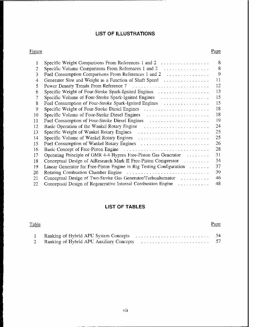
LIST OF ILLUSTRATIONS
Figure Page
1 Specific Weight Comparisons From References 1 and 2 8 2 Specific Volume Comparisons From References 1 and 2 8 3 Fuel Consumption Comparisons From References 1 and 2 9 4 Generator Size and Weight as a Function of Shaft Speed 11 5 Power Density Trends From Reference 7 12 6 Specific Weight of Four-Stroke Spark-Ignited Engines 13 7 Specific Volume of Four-Stroke Spark-Ignited Engines 15 8 Fuel Consumption of Four-Stroke Spark-Ignited Engines 15 9 Specific Weight of Four-Stroke Diesel Engines 18
10 Specific Volume of Four-Stroke Diesel Engines 18 11 Fuel Consumption of Four-Stroke Diesel Engines 19 12 Basic Operation of the Wankel Rotary Engine 24 13 Specific Weight of Wankel Rotary Engines 25 14 Specific Volume of Wankel Rotary Engines 25 15 Fuel Consumption of Wankel Rotary Engines 26 16 Basic Concept of Free-Piston Engine 28 17 Operating Principle of GMR 4-4 Hyprex Free-Piston Gas Generator 31 18 Conceptual Design of AiResearch Mark II Free-Piston Compressor ......... 34 19 Linear Generator for Free-Piston Engine in Rig Testing Configuration 37 20 Rotating Combustion Chamber Engine 39 21 Conceptual Design of Two-Stroke Gas Generator/Turboalternator 46 22 Conceptual Design of Regenerative Internal Combustion Engine 48
LIST OF TABLES
Table Page
1 Ranking of Hybrid APU System Concepts 54 2 Ranking of Hybrid APU Auxiliary Concepts 57
Vll
I. INTRODUCTION
The Advanced Research Projects Agency (ARPA) has taken an initiative in developing hybrid
vehicle technology, focusing on the unconventional technologies needed to make hybrid vehicles
successful as energy-saving and pollution-reducing alternatives to current automotive technology.
The model hybrid electric drivetrain consists of an auxiliary power unit (APU) comprising a
combustion engine driving an electric generator, an electric power storage device (battery),
electric traction motors, and a control system. The APU must provide electric power under
conditions very different from the conventional automotive driving cycle and must meet a
different set of objectives. It is natural, then, that the power plant itself may be unconventional.
This study explores the alternative combustion engine power plants that may be used for hybrid
electric vehicles. The intent is to discriminate between both conventional and unconventional
alternatives to find those concepts that are most worthy of further study in the form of
simulation, analysis, and ultimately, prototype demonstration.
The study was initiated as a brainstorming exercise among a number of engineers at Southwest
Research Institute (SwRI) involved in engine design and development, and in hybrid vehicle
development. The author then proceeded to review the literature available on conventional and
unconventional engines and develop a list of concepts, which were then assessed and ranked
according to their perceived ability to meet the objectives of a hybrid APU. The concepts,
criteria, and ranking are discussed in this report, and recommendations for further study are
provided.
II. OBJECTIVE
The objective of this study is to discern which concepts for combustion engines are the best
choices for detailed study as alternative power plants to the conventional reciprocating engine in
application to hybrid electric vehicle APUs. The study is limited to internal combustion engines
or reciprocating external combustion (Stirling) engines suitable for coupling to electric generators;
turbine engines, fuel cells, and other concepts are also viable alternatives but are not considered

here. The criteria are tailored for series-type hybrid drivetrains in which the combustion engine
drives electric generation as a supplemental charging source for battery storage. Other types of
hybrid drives are possible, such as a parallel arrangement whereby the combustion engine directly
drives the traction wheels through a transmission in combination with electric motors (the criteria
for these systems will be markedly different).
111. CRBTERIÄ
Hybrid powertrains are considered alternatives to conventional combustion engines for two
primary reasons: fuel economy and emissions. The fuel economy benefit arises from two
fundamental factors: power leveling by energy storage in the batteries, and the ability to operate
the APU power plant at constant, peak efficiency conditions. Emissions are improved because
the overall fuel consumption is low, allowing the engine to operate at a near steady state cycle.
Thus, the criteria for selection of an engine for a hybrid vehicle are very different from those for
a conventional automotive power plant. The criteria that are important to hybrid APUs are listed
below, roughly in their order of precedence.
A. Power Density
The volume available for the power plant is limited, as space must be allotted for energy storage,
traction motors, generator, and controls, as well as the engine itself. The weight is important,
since vehicle weight directly impacts fuel economy. High power density, in terms of both power-
to-volume ratio and power-to-weight ratio, is desirable. Power density in consideration of both
engine and generator tends to favor high-speed engines, as the generator volume and weight for
a given power rating decreases with increasing speed.
EL Emissions
If an engine has good power density but substantially worse emissions characteristics than its
conventional competitor, it ultimately will not fulfill the objectives of hybrid vehicles. Thus,
2
concepts that improve power density at the expense of emissions will not be completely
satisfactory. However, brake-specific emissions that are higher than the conventional technology
may be tolerable as the duty factor for the APU is much lower than the conventional drivetrain.
C. Thermal Efficiency
Thermal efficiency—a measure of fuel economy-must be high to achieve overall vehicle fuel
economy benefits over conventional drivetrains. While the hybrid drivetrain has key advantages,
it must also overcome losses associated with energy storage and retrieval, and generator and
motor inefficiencies, as well as the simple problem that the package generally tends to be heavier
than a conventional drivetrain.
D. Cost
To be competitive as a commercial product, a hybrid vehicle must have comparable cost to
conventional vehicles. This equation will have to factor in total life cycle costs, which include
reduced fuel cost as well as the expense of battery replacement and system maintenance. It is
clear that the drivetrain will be significantly more expensive due primarily to the energy storage
system. Thus, the engine itself will have to be as inexpensive as possible.
E. Transient Response
Transient response characteristics of a hybrid APU are a lower priority, as the system is designed
to operate at near steady state conditions. However, a rapid transient response is desirable for
rapid engine catalyst warm-up, assuming a catalyst is used. The response of most interest is the
start-up from cold to full power.
F. Producibility
Closely linked to the cost issue is the producibility of the engine. Will it be manufactured by
conventional methods, or will new or expensive, unconventional processes be required?

Also ultimately a life cycle cost issue, the reliability of combustion engines is a factor to
consider. Many small power plants for utility applications are designed for much shorter life than
their automotive counterparts. However, engine replacement or major overhaul should not be any
more frequent for hybrid powertrains than for conventional engines. The design of APU engines
for reliability must take into account the high power factor. The APU will be operated primarily
at its design point, instead of primarily at low load conditions like a conventional automotive
During start-up, most engines absorb a considerable amount of power from the starter motor to
overcome friction and inertia. This start-up energy can be characterized as the cranking torque
and is highly dependent upon engine design. It is a direct penalty to overall thermal efficiency
and must be taken into consideration for drivetrains where the APU is cycled frequently between
running and nonrunning conditions.
and Hairsnness
Noise, vibration, and harshness (NVH) are measures of the comfort level of passengers in
vehicles or of bystanders. These factors are increasingly important for customer satisfaction and
acceptance. In this regard, the hybrid drivetrain should not be appreciably worse, and preferably
should be better than its conventional counterpart.
Technical Rist
The technical risk of a new concept is not a measure of how well it will perform its intended
function, but of how much is unknown about its viability, and how much research effort may
need to be expended to make it viable.

K. Multifuel Capability
Some engine concepts are limited to certain types of fuel. Alternative fuels such as natural gas
and methanol are of increasing interest primarily due to environmental concerns. The ability to
be tolerant of different fuels would be an advantage.
IV. RANKING PROCEDURE
As a systematic means of distinguishing between APU concepts, a ranking procedure was
applied. In this procedure, each concept was assigned a score relative to each of the previously
described criteria. The criteria were also weighted according to their importance in the APU
application. Where possible, the assigned scores were based on actual quantifiable data. Thermal
efficiency is defined as the ratio of electric power out to fuel energy in. The power density for
an engine type is scored as an actual (reciprocal) specific weight in kW/kg, or specific volume
in kW/L (the reciprocal is used to conform to the overall strategy of "higher is better"). For
parameters which have no quantifiable level, a relative score was assigned with a baseline level
of 1.0. Weighting factors were assigned as the product of a normalizing factor established as the
reciprocal of the difference between maximum and minimum values of the parameter, and a
significance weight in the range of 0 through 5.
V. STATE-OF-THE-ART
As part of this study, an extensive literature review was conducted to assess the current state-of-
the-art for automotive combustion engines and particularly for hybrid APUs in relation to the
above criteria, and to examine the potential for advanced concepts to improve the state-of-the-art.
It is important to understand the best attainable performance of a conventional engine-generator
combination in order to assess the value of unconventional technologies in improving this
performance. During this study, a total of 58 references were reviewed. Supplementary
information was obtained from the SwRI engine database, which is a comprehensive listing of
published data on reciprocating engines from all over the world.
One key reference is a similar study that was conducted eleven years ago by JPL for the U.S.
Department of Energy Q)*, written by Mr. H.W. Schneider. The objectives of that study were
somewhat different in that the primary focus was for parallel drivetrains; however, the document
fairly summarizes the state-of-the-art for that time, and also makes recommendations for series
drivetrains. The author considers in his discussion the following alternatives:
° Four-stroke piston engines
° Four-stroke rotary engines (Wankel) 0 Two-stroke piston engines
° Indirect injection diesel engines
° Direct injection diesel engines
° Brayton cycle engines (gas turbine)
° Stirling engines
° Rankine cycle engines (steam engine)
<= Free-piston engines.
After consideration of the relative merits for series drivetrains, the author recommended research
to be prioritized as follows: direct-injected spark-ignited two-stroke engines, fuel-injected rotary
engines, and free-piston engines.
This study was revised and updated in 1992 by A.F. Burke, with special consideration of the
driving cycle requirements for a series hybrid drivetrain. (2) The developments in the years
between 1984 and 1992 had made the series option more feasible, primarily because of
advancements in electric drivetrain component sizes and efficiencies. For a series drivetrain
application to a passenger car, gradability and minimum sustained highway speed requirements
dictate an APU of about 25 to 30 kW output, suggesting that an appropriate target power rating
Underscored numbers in parentheses refer to the list of references at the end of this report.
6

for the engine is 30 kW. Mr. Burke places a lower priority on fuel economy for the combustion
engines in a series drivetrain because the vehicle is assumed to be operating in a purely electric
mode for 80 to 90 percent of the driving miles, based on results of a Monte Carlo analysis of
typical driving patterns.(3) For the series hybrid, start-stop operation is also less of a
consideration than for the parallel configuration because the periods of continuous operation and
continuous non-operation are longer. According to Mr. Burke's analysis, the series drivetrain
may go for days at a time without using the heat engine due to short urban trips with battery
charging from the wall plug between trips. In a similar study, Mr. Burke focussed on the effects
of start-stop operation indicating that for range extender type operation, where the vehicle would
be operated for extended periods in highway driving with fairly low, continuous power demand,
the overall fuel economy could be greatly improved if the APU were operated intermittently at
its peak efficiency rather than continuously at low load. (4) These updates redefined the APU
engine development priorities as 1) rotary, 2) direct injection two-stroke, and 3) gas turbine
engines, omitting discussion of Stirling, Rankine, or free-piston engines.
The survey of literature done by Mr. Schneider and updated by Mr. Burke distills the state-of-the-
art into estimates of performance and power density attainable by the various current technology
engine types. These summaries are included in the Appendix, which also incorporates data from
other sources as described below. Figure 1 shows the projections of specific weight for the
conventional technology engines, as presented by these two references.
In the legend, "2-S SI" refers to two-stroke spark-ignition engines, "Rotary" to Wankel-type
rotary engines, "4-S SI" to four-stroke spark-ignition engines, "4-S DI CI" to four-stroke direct
injection compression ignition (Diesel) engines, and "4-S IDI CI" to four-stroke indirect injection
compression ignition (Diesel) engines. The later reference applies a bit more pessimism to the
two-stroke gasoline engines but still ranks them at the lowest specific weight. Schneider
presented both DI and IDI diesel engines but discounted them as contenders for the APU due to
high specific volume and weight; Burke did not consider these engines. Burke was more
optimistic for rotary and four-stroke spark-ignition engines. Figure 2 shows the comparison for
specific volumes, which follows similar trends to specific weight. However, Burke was more

2-SSI Rotary 4-SSI 4-S DI CI 4-S IDI CI
M Schneider D Burke li This Study]
Figure 1. Specific weight comparisons from References 1 and 2
^3
«i
o2 > o
I W 1 --
0 -I 2-SSI
=H
W8&
I
S*K$
:•:•:•:•:•:•:■:
t:::::::::%
Rotary 4-SSI 4-SDICI 4-S IDI CI
Schneider O Burke II This Study
Figure 2, Specific vofairoe comparisons from References 1 and 2

pessimistic than Schneider in his predictions. In terms of fuel consumption (see Fig. 3), the two-
stroke spark-ignition engine was a strong contender, with fuel economy approaching or exceeding
that of the IDI diesel. Fuel economy (along with simplicity) was a key reason for Schneider's
recommending the two-stroke SI engine. Burke's update has added some pessimism to this
prediction, but this engine still appears to be a strong contender in his analysis. Of course, the
DI diesel scores best in fuel consumption, but it is still discounted by these researchers because
of its perceived weight and volume penalties.
Reference 5 analyzes key driving conditions of acceleration, gradability, and steady state fuel
economy and compares alternative engines in application to a range-extender vehicle (REV)
based on an existing Ford Taurus platform (two other platforms were analyzed but not explicitly
discussed in the reference). This study determined that the power rating for the APU engine
should be in the range of 25 to 50 kW for this type of application. Several alternative engines
were considered as substitutes for a small (6.5-kW) genset that was considered in a previous
0.3
i0-25
.1 0.2 -4-» Q, E |0.15 o U
3 0.1 Us o
ta "§ 0.05 a,
r,l
Ja. 2-SSI Rotary
■+■ 4-S SI 4-S DI CI 4-S IDI CI
Schneider O Burke Hi This Study
Figure 3. Fuel consumption comparisons from References 1 and 2

phase ofthat analysis. The alternatives included the Orbital OCP "X" engine rated at 37.6 kW,
the GM Quad 4 four-stroke SI engine rated at 62.7 kW, the Nomac gas turbine genset at
24.0 kW, the NASA Series 70 rotary engine at 28.1 kW, and an MTI Mod II Stirling engine at
32.2 kW. The comparison criteria based on vehicle performance with these options are not very
useful in distinguishing between alternative engine categories because the power ratings of the
different engines vary widely. Obviously, acceleration and gradability criteria favored the larger
power plants, whereas fuel economy favored the Stirling engine. This reference does provide a
useful comparison of performance data for several state-of-the-art engine categories, which is
included in the Appendix.
The current state-of-the-art for conventional technologies is discussed in the sections that follow.
In this context, conventional technologies are those currently in production for automotive
engines, or in imminent production status. Such technologies as free-piston engines or Stirling
engines are still very much in the research stage and will therefore be considered as advanced
concepts.
A„ Generator Techoology
Since the objective is electric power out, the generator characteristics must be considered as well
as the engine characteristics. The power density of conventional rotating generators is
significantly enhanced by increasing the shaft speed. The efficiency is less affected, as proper
design can achieve high efficiency at virtually any design speed. At higher speeds, windage
losses tend to degrade the efficiency somewhat; however, for this study, it is assumed that
efficiency is constant with speed. For those concepts that work with a conventional rotating
generator, it is assumed that the generator efficiency is 92 percent. The overall design
requirements of a hybrid APU favor those engines that have higher shaft speed for compactness
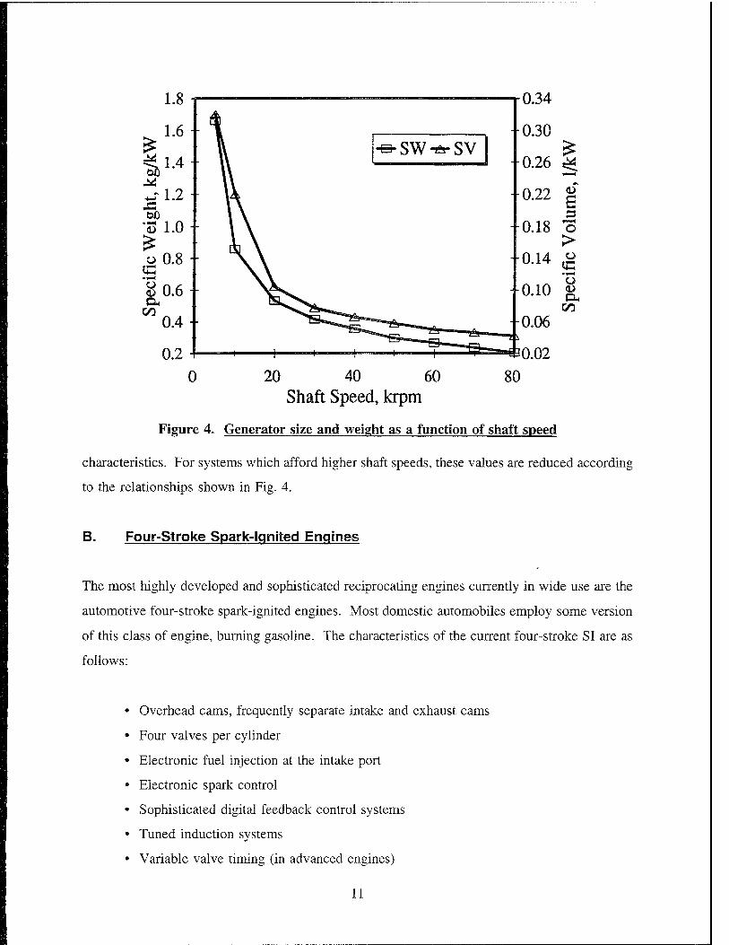
of both engine and generator. Figure 4 shows the characteristic tradeoff of generator size and
weight with shaft speed for a 25-kW generator.© For a baseline unit operating at 6,000 rpm
and generating 30 kW, specific volume and weight are assumed to be 0.3 L/kW and 1.5 kg/kW,
respectively. These values are additive to engine specific volume and weight to obtain system
10
1.8 i
1 6 -
r-0.34
0.30 5 *j 1.2 ■
*53 1.0 -
o 0.8 - IS
-e-SW-A- SV 0.26 ^
-0.22 |
0.18 o >
0.14 o
8 0.6 - a co
0.4-
o.io & CO
-0.06
0 20 40 60 80 Shaft Speed, krpm
Figur« e4. Generator size and weight as a function of shaft speed
characteristics. For systems which afford higher shaft speeds, these values are reduced according
to the relationships shown in Fig. 4.
B. Four-Stroke Spark-Ignited Engines
The most highly developed and sophisticated reciprocating engines currently in wide use are the
automotive four-stroke spark-ignited engines. Most domestic automobiles employ some version
of this class of engine, burning gasoline. The characteristics of the current four-stroke SI are as
follows:
• Overhead cams, frequently separate intake and exhaust cams
• Four valves per cylinder
• Electronic fuel injection at the intake port
• Electronic spark control
• Sophisticated digital feedback control systems
• Tuned induction systems
• Variable valve timing (in advanced engines)
11

° Variable intake geometry (in advanced engines)
° Lightweight materials (aluminum, plastics, composites).
Most of these technologies have not yet been incorporated in engines of the size class appropriate
to hybrid APUs. Turbocharging was a common feature of automotive engines in the mid-1980s
but has gradually disappeared due primarily to durability issues and cost, the advantages in power
density being largely displaced by the improvements due to other technologies. The durability
problems with turbocharging the SI engine are attributed to high turbine inlet temperatures, since
these engines run with stoichiometric fuel-air ratios. Figure 5 (reproduced from Reference 7)
illustrates the trends in power density based on ninety 1988 passenger car engines. Those
engines incorporating multivalve technology approach the turbocharged engines in power density.
It seems unlikely that turbocharging will be a feasible option to obtain high power density on an
SI engine of the power class needed for a hybrid vehicle APU. The remaining technologies
previously listed are all feasible for consideration in the development of the hybrid APU.
300
250
200
ß?150
100
100 iSPLACEMENT (5n.3)
200 300 400
12 3 4 5 DISPLACEMENT (L)
Figure 5. Power density trends from Reference 7
12

TABLE A-l in the Appendix summarizes the state-of-the-art of automotive SI gasoline engines,
based on the current literature. Production engines are shown along with racing engines to
illustrate the range of performance attainable by applying higher technologies.
Figure 6 shows the state-of-the-art for specific weight for four-stroke spark-ignition engines.
There is a noticeable increase in specific weight as the power drops below 50 kW into the size
class appropriate to APUs. The best obtained specific weight for a 30-kW engine is about
1.9 kg/kW, slightly higher than values suggested by Schneider and Burke. However, the
significant sensitivity to power rating in this range (and the lack of engines at 30- to 40-kW
rating) suggests that this level may be challenged by focused effort on this application using
existing technologies. The higher specific weight of engines below 30-kW output is likely
attributable to the lack of penetration of the latest automotive technologies listed above. It is not
unreasonable to presume that a small (30-kW) engine incorporating the latest technologies could
achieve specific weight of 1.2 kg/kW.
10 «P
an
□□□
H H
0 40 80 120 Rated Power, kW
160 200
Figure 6. Specific weight of four-stroke spark-ignited engines
13
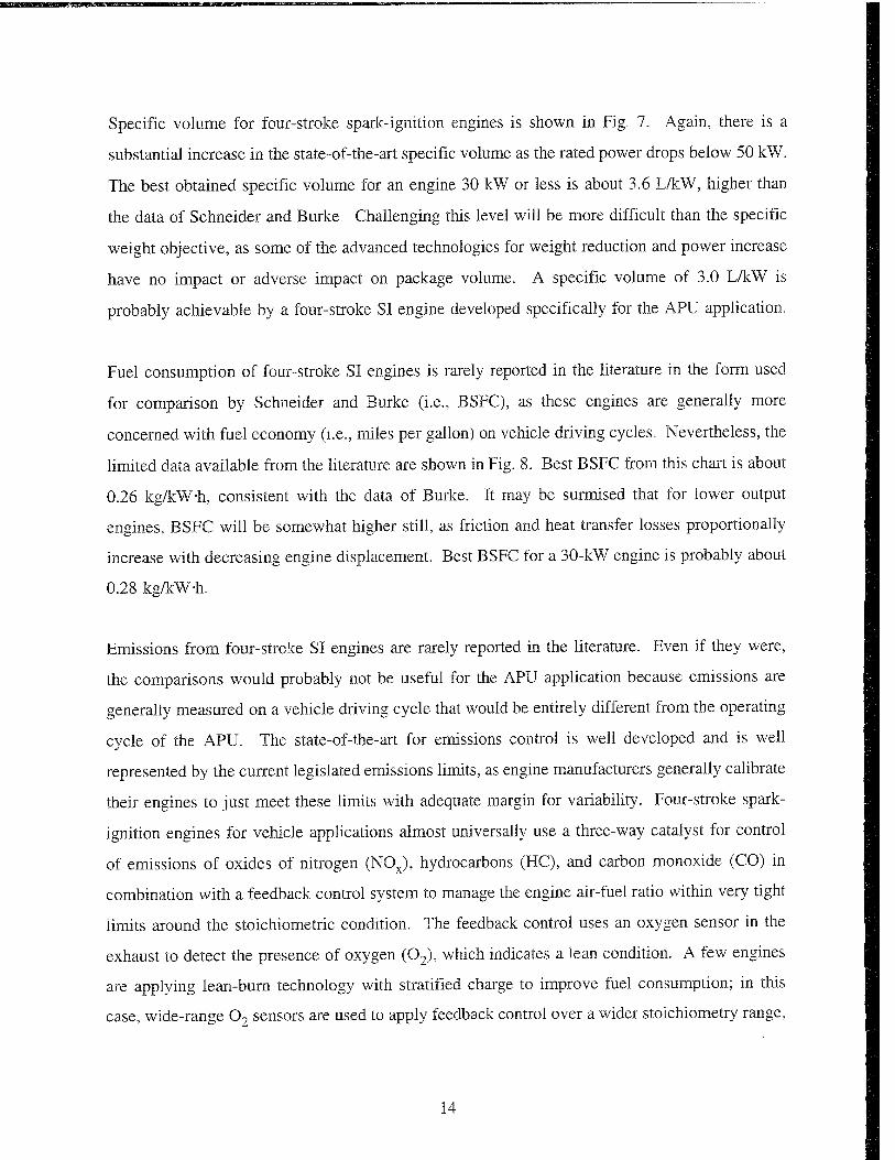
Specific volume for four-stroke spark-ignition engines is shown in Fig. 7. Again, there is a
substantial increase in the state-of-the-art specific volume as the rated power drops below 50 kW.
The best obtained specific volume for an engine 30 kW or less is about 3.6 L/kW, higher than
the data of Schneider and Burke. Challenging this level will be more difficult than the specific
weight objective, as some of the advanced technologies for weight reduction and power increase
have no impact or adverse impact on package volume. A specific volume of 3.0 L/kW is
probably achievable by a four-stroke SI engine developed specifically for the APU application.
Fuel consumption of four-stroke SI engines is rarely reported in the literature in the form used
for comparison by Schneider and Burke (i.e., BSFC), as these engines are generally more
concerned with fuel economy (i.e., miles per gallon) on vehicle driving cycles. Nevertheless, the
limited data available from the literature are shown in Fig. 8. Best BSFC from this chart is about
0.26 kg/kW-h, consistent with the data of Burke. It may be surmised that for lower output
engines, BSFC will be somewhat higher still, as friction and heat transfer losses proportionally
increase with decreasing engine displacement. Best BSFC for a 30-kW engine is probably about
0.28 kg/kW-h.
Emissions from four-stroke SI engines are rarely reported in the literature. Even if they were,
the comparisons would probably not be useful for the APU application because emissions are
generally measured on a vehicle driving cycle that would be entirely different from the operating
cycle of the APU. The state-of-the-art for emissions control is well developed and is well
represented by the current legislated emissions limits, as engine manufacturers generally calibrate
their engines to just meet these limits with adequate margin for variability. Four-stroke spark-
ignition engines for vehicle applications almost universally use a three-way catalyst for control
of emissions of oxides of nitrogen (NOx), hydrocarbons (HC), and carbon monoxide (CO) in
combination with a feedback control system to manage the engine air-fuel ratio within very tight
limits around the stoichiometric condition. The feedback control uses an oxygen sensor in the
exhaust to detect the presence of oxygen (02), which indicates a lean condition. A few engines
are applying lean-burn technology with stratified charge to improve fuel consumption; in this
case, wide-range 02 sensors are used to apply feedback control over a wider stoichiometry range,
14

10
I B 3 o >
is • I-H O s.
8 --
6 -
4-.
2--
ff
r?
D
D
B
□
m
1
w □ n □ n □
-, no □ D
D
D
D
1
a
! H 1 -+■ —1 1 1 0
0 40 80 120 160 200 Rated Power, kW
Figure 7. Specific volume of four-stroke spark-ignited engines
0.4 i
0.35
£ 0.3 -
•* 0.25 u SS 0.2 + CO
0.15 +
0.1 -! 0
H h i !
40 80 120 Rated Power, kW
160 200
Figure 8. Fuel consumption of four-stroke spark-ignited engines
15

and NOx is controlled by a combination of three-way catalyst and lean burn for lower in-cylinder
temperatures. However, this technology is going the wrong direction for hybrid APUs, as it
reduces power density.
A key consideration in emissions of gasoline engines for hybrid APUs, as it is for conventional
vehicle applications, is the catalyst warm-up period. At start-up, the catalyst is cold and
ineffective, and warm-up takes several minutes until the catalyst is fully effective. During this
period, HC and CO emissions are high, both because of catalyst ineffectiveness and high engine-
out emissions due to flame quenching on the cold cylinder internal surfaces and start-up
enrichment of the fuel-air mixture. In conventional drivetrains, this happens only once per drive
cycle. In hybrid applications, particularly for serial drivetrains, it may happen many times over
the driving cycle. The problem will be highly sensitive to the control of the APU, in terms of
the number of start-stop cycles encountered and the time between operating cycles during which
the catalyst and engine cool down. An electrically heated catalyst can be used to overcome the
problem of catalyst warm-up, at some added cost and penalty in power consumption. The APU
engine application, then, will favor engines that have a short warm-up cycle and good combustion
characteristics during cold start such that cold-start enrichment can be minimized. This will favor
gaseous fuels over gasoline, and application of advanced techniques such as high in-cylinder
turbulence, variable valve timing, and variable intake geometry.(8-10).
For the purpose of ranking, the four-stroke SI engines are assigned scores according to the above
arguments for power density and fuel economy; on other criteria, the four-stroke SI engines are
considered to be the baseline and are assigned a score of 1.0.
C„ Four-Stroke Compression Ignition Engines
Diesel engines were largely discounted by Schneider and Burke because of a perception of low
power density. This is a result of high cylinder pressures requiring heavier cylinder, piston and
head structure, and lean-burn operation, which necessitates a higher air consumption than the
comparative stoichiometric spark-ignition engines to achieve a target power level. With regard
to technological development, these engines are highly developed for medium-duty and heavy-
16
duty highway vehicles, and also highly developed for stationary utility applications where weight
is not a major issue. However, they are not highly developed in high power-density applications.
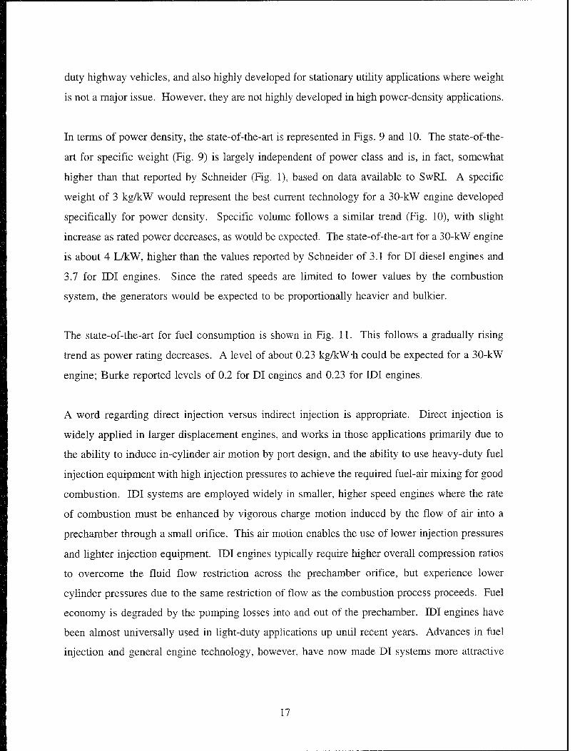
In terms of power density, the state-of-the-art is represented in Figs. 9 and 10. The state-of-the-
art for specific weight (Fig. 9) is largely independent of power class and is, in fact, somewhat
higher than that reported by Schneider (Fig. 1), based on data available to SwRI. A specific
weight of 3 kg/kW would represent the best current technology for a 30-kW engine developed
specifically for power density. Specific volume follows a similar trend (Fig. 10), with slight
increase as rated power decreases, as would be expected. The state-of-the-art for a 30-kW engine
is about 4 L/kW, higher than the values reported by Schneider of 3.1 for DI diesel engines and
3.7 for IDI engines. Since the rated speeds are limited to lower values by the combustion
system, the generators would be expected to be proportionally heavier and bulkier.
The state-of-the-art for fuel consumption is shown in Fig. 11. This follows a gradually rising
trend as power rating decreases. A level of about 0.23 kg/kW-h could be expected for a 30-kW
engine; Burke reported levels of 0.2 for DI engines and 0.23 for IDI engines.
A word regarding direct injection versus indirect injection is appropriate. Direct injection is
widely applied in larger displacement engines, and works in those applications primarily due to
the ability to induce in-cylinder air motion by port design, and the ability to use heavy-duty fuel
injection equipment with high injection pressures to achieve the required fuel-air mixing for good
combustion. IDI systems are employed widely in smaller, higher speed engines where the rate
of combustion must be enhanced by vigorous charge motion induced by the flow of air into a
prechamber through a small orifice. This air motion enables the use of lower injection pressures
and lighter injection equipment. IDI engines typically require higher overall compression ratios
to overcome the fluid flow restriction across the prechamber orifice, but experience lower
cylinder pressures due to the same restriction of flow as the combustion process proceeds. Fuel
economy is degraded by the pumping losses into and out of the prechamber. IDI engines have
been almost universally used in light-duty applications up until recent years. Advances in fuel
injection and general engine technology, however, have now made DI systems more attractive
17

80 120 Rated Power, kW
Figure 9c Specific weight of four-stroke diese! engines
2(
10 T
6
o
O
D
a a
Ö3_n □ n B q$3
Sn an
Ob
40 80 120 160 Rated Power, kW
Figure 10. Specific volume of four-stroke diesel engines
200
18

0.4 1
0.35 - -
£ 0.3
•* 0.25
- -O D
0.15
0.1
o_ n o ft □
□ JO. üB n
0 40 80 120 Rated Power, kW
160 200
Figure 11. Fuel consumption of four-stroke diesel engines
to the automotive community. Particularly in Europe, the automotive DI diesel engine is making
significant inroads. Audi produces perhaps the best engine in this class.(ll) There is no
fundamental reason why this technology cannot be applied to smaller output engines.
Emissions from diesel engines behave quite differently from those of spark ignition engines. The
key emissions are particulates and NOx. Substantial amounts of hydrocarbons can also be
emitted, particularly during cold start. Aftertreatment for oxidation control of particulates and
hydrocarbons is being introduced for many 1994 engines, but it is not as effective as
aftertreatment for SI engines. Aftertreatment for NOx is not yet feasible. Particulates are
primarily produced when the engine undergoes hard transient load application or operates at high
torque and low speed. NOx primarily results from high load operation where the in-cylinder
temperatures are highest. These engines offer the potential to be very low emitters when properly
warmed up and when operated at constant speed and load outside the regions of high NOx
emissions; however, their power density at these conditions is not very good. The baseline
emissions score assigned to diesel engines is 0.9.
19

The cost of current diesel engines is somewhat higher than that for SI engines as a result of more
sophisticated fuel injection equipment and generally robust construction. However, higher
technology SI engines are comparable in cost and may be more expensive and heavier if designed
to equivalent reliability, which is excellent for diesel engines. Producibility is comparable to
four-stroke SI engines. Transient response is slightly worse than that for SI engines because of
larger reciprocating and rotating mass.
Cranking torque is an issue with diesel engines because of the high compression needed to attain
the temperatures to sustain combustion. Smaller engines are more of a problem in this area
because of torque fluctuations with fewer cylinders. Cold startability of smaller engines is also
a concern because of higher relative heat transfer from the combustion chamber. This may
become an issue with APUs in frequent start-stop operation. However, with appropriately
designed power electronics and controls, the generator can also be used as a starter motor,
providing high cranking torque to overcome these issues.
NVH problems are significant for diesel engines, primarily due to the high rate of pressure rise
in the initial stages of combustion. Automotive diesel engines are typically associated with a
"clatter" noise, the sound of diesel combustion. This noise can be regulated by injection rate
control and by turbocharging, at significant increase in cost. Turbocharging may not be an option
for a 30-kW engine.
Multifuel capability is less with diesel engines than with SI engines when considering light
hydrocarbons. Diesel combustion will only work with fuels that contain significant quantities
of long-chain hydrocarbons, which will initiate the combustion process by thermal decomposition
to shorter molecules and free radicals. Organic fuels such as vegetable oils are potential
alternatives, but natural gas, propane, hydrogen, or other alternatives cannot be used without
significant changes to the combustion system.
20
D. Two-Stroke Spark-Ignited Engines
The top ranking in the analyses by Schneider and Burke for two-stroke SI engines was based on
the status of research at that time, indicating great promise for automotive two-strokes with direct
fuel injection. Eleven years later, these engines have not yet lived up to their predictions of rapid
inroads into automotive application. The primary reasons for this slower-than-expected
development are difficulties with durability and emissions. The durability issues are associated
with lubrication of the piston-ring-cylinder wall interface, particularly where the rings are used
to control ports in the cylinder walls for admission of air and exhaust of products. Durability
of crankshaft parts is also an issue in those engines that utilize crankcase pumping as a means
of supplying scavenging air and cannot use conventional pressure lubrication and plain bearings.
Catalyst durability is a problem because of the presence of lubricating oil in the exhaust. The
emissions issues are related to the fact that two-stroke engines inherently contain excess oxygen
in the exhaust, which makes the application of three-way catalysts impossible. Unburned
hydrocarbons and CO can be effectively treated with oxidation catalysts, but research has yet to
perfect a lean catalyst for NOx emissions. Nevertheless, research continues into automotive two-
stroke engines, and reports from key developers such as Orbital Engine Company and Chrysler
suggest that these problems are not insurmountable.
The key advantages of the two-stroke engine are small, lightweight construction (high power
density, both volumetric and weight) and low cost associated with smaller parts count. The
elimination of the overhead valvetrain is largely responsible for both of these advantages; yet
some researchers are still applying overhead valves in their two-stroke engines to overcome the
durability and exhaust oil contamination issues.(12-15)
The availability of specific engine data for automotive class two-stroke engines is poor because
of the highly competitive environment; current developers are not anxious to release their data.
Thermal efficiency gains attributed to lower friction are generally offset by losses associated with
scavenging and pumping; thus, thermal efficiency of the two-stroke engines is comparable to that
of four-stroke engines. Information obtained in an industry survey by SwRI in 1991 indicates
that automotive class engines can achieve a specific weight of 0.9 kg/kW Q6); this level is also
21
probably reasonable for APUs. Despite higher "weight overhead" associated with smaller size,
these engines would also benefit from power density associated with higher speed. No data was
obtained on specific volume, but a level of 0.7 times that for four-stroke SI engines is reasonable,
accounting for the reduction in engine height associated with elimination of the overhead valves,
and for the reduced size and weight of a generator running at higher speed.
Cost of piston-ported two-stroke engines is significantly lower than the poppet-valved engines
because of the greater simplicity and lower parts count. The same argument holds for gains in
producibility and reliability. Emissions are harder to control. The technical risk is higher
because of the immaturity of this technology. NVH is probably about the same as with four-
stroke engines. Mechanical noise may be lower without the valvetrain, but exhaust noise and
bearing noise are increased for two-strokes with rolling-element bearings. Transient response
should be better than for a four-stroke engine because of reduced overall inertia. Cranking torque
fluctuations for a multicylinder engine should be lower because there is a compression stroke on
each revolution.
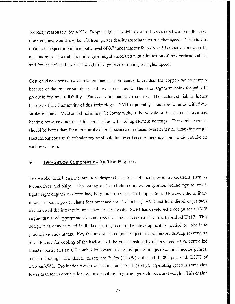
E„ Two-Stroke Compression legnation Engines
Two-stroke diesel engines are in widespread use for high horsepower applications such as
locomotives and ships. The scaling of two-stroke compression ignition technology to small,
lightweight engines has been largely ignored due to lack of application. However, the military
interest in small power plants for unmanned aerial vehicles (UAVs) that burn diesel or jet fuels
has renewed the interest in small two-stroke diesels. SwRI has developed a design for a UAV
engine that is of appropriate size and possesses the characteristics for the hybrid APU.(iZ) This
design was demonstrated in limited testing, and further development is needed to take it to
production-ready status. Key features of the engine are piston compressors driving scavenging
air, allowing for cooling of the backside of the power pistons by oil jets; reed valve controlled
transfer ports; and an IDI combustion system using low pressure injectors, unit injector pumps,
and air cooling. The design targets are 30-hp (22-kW) output at 4,500 rpm, with BSFC of
0.25 kg/kW-h. Production weight was estimated at 35 lb (16 kg). Operating speed is somewhat
lower than for SI combustion systems, resulting in greater generator size and weight. This engine
22
will be the benchmark for comparison. For greater reliability, some weight would be expected
to be added to this engine design, such that estimated engine weight for a hybrid APU would be
around 22 kg. Because of the high compression ratio requirements and the heat losses working
against compression ignition, cranking torque and cold startability will be somewhat worse than
with spark-ignited engines.
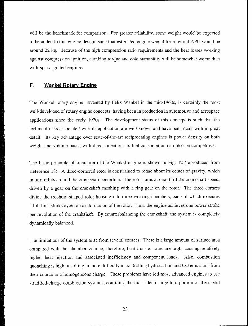
F. Wankel Rotary Engine
The Wankel rotary engine, invented by Felix Wankel in the mid-1960s, is certainly the most
well-developed of rotary engine concepts, having been in production in automotive and aerospace
applications since the early 1970s. The development status of this concept is such that the
technical risks associated with its application are well known and have been dealt with in great
detail. Its key advantage over state-of-the-art reciprocating engines is power density on both
weight and volume basis; with direct injection, its fuel consumption can also be competitive.
The basic principle of operation of the Wankel engine is shown in Fig. 12 (reproduced from
Reference 18). A three-cornered rotor is constrained to rotate about its center of gravity, which
in turn orbits around the crankshaft center line. The rotor turns at one-third the crankshaft speed,
driven by a gear on the crankshaft meshing with a ring gear on the rotor. The three corners
divide the trochoid-shaped rotor housing into three working chambers, each of which executes
a full four-stroke cycle on each rotation of the rotor. Thus, the engine achieves one power stroke
per revolution of the crankshaft. By counterbalancing the crankshaft, the system is completely
dynamically balanced.
The limitations of the system arise from several sources. There is a large amount of surface area
compared with the chamber volume; therefore, heat transfer rates are high, causing relatively
higher heat rejection and associated inefficiency and component loads. Also, combustion
quenching is high, resulting in more difficulty in controlling hydrocarbon and CO emissions from
their source in a homogeneous charge. These problems have led most advanced engines to use
stratified-charge combustion systems, confining the fuel-laden charge to a portion of the useful
23

Figure 12. Basic operation of the Wankel rotary engine
volume, which reduces the power density. The high heat transfer rates cause cooling problems
in the rotor, since a large portion of its surface is exposed to hot gases. Internal cooling by oil
is the most common method of rotor cooling; air-cooled engines have great difficulty in this area.
Sealing of the rotor apex and sides has been the focus of much development, and problems in
these areas are generally solved; however, the large amount of rubbing contact, along with fairly
high operating speeds, leads to higher friction in comparison with piston engines.
Despite these issues, the Wankel rotary engine has experienced some degree of success in
research applications where high power density is a priority, and still retains interest among
developers of lightweight aircraft, particularly unmanned aerial vehicles. Significant development
activities continue for commercial and military applications at Mazda Motor Corporation Q9, 20),
John Deere Technologies International, Inc. (now Rotary Power International) (1_8, 21, 22), and
AAI Corporation (23). Also, a single-rotor air-cooled engine of 38-hp output is manufactured
for UAV and target drone applications by Al vis UAV Engines Ltd. (24) The available data
regarding Wankel engine power density and fuel economy are shown in Figs. 13 through 15.
From the limited data available, it is clear that these engines significantly challenge the power
24

0 40 80 120 Rated Power, kW
160 200
Figure 13. Specific weight of Wankel rotary engines
0 40 80 120 Rated Power, kW
160 200
Figure 14. Specific volume of Wankel rotary engines
25

035
^ 0.25 --
w 0.2 - -
80 120 160 200 Rated Power, kW
Figrare 15. Fuel consumption of Wankel rotary engines
density of conventional reciprocating engines in the under 40-kW power class and can nearly
compete with conventional technology in fuel consumption.
For an engine developed for the APU system, thermal efficiency could be expected to be 27
percent; coupled with the generator, overall efficiency would be 25 percent. Engine specific
weight and volume of about 0.7 kg/kW and 0.6 L/kW, respectively, appear feasible. Operating
speed could be at about 8,000 rpm, resulting in generator specific weight and volume of
1.18 kg/kW and 0.26 L/kW, respectively.
Cost of the Wankel engine should be close to that of conventional two-stroke engines due to the
simplicity of the mechanism. Emissions may be more difficult to control. Producibility and
reliability should be good. Since there is no reciprocating motion, the sliding surfaces never
reverse their sliding motion, which is a prime cause of wear in reciprocating engines. Also,
Wankel engines use total consumption lubrication, which means that fresh oil is continually
supplied to the rubbing surfaces and cannot become degraded or diluted by mixing with fuel.
The technical risks are well established but somewhat higher than for conventional four-stroke
engines. Noise and vibration are well controlled by the balanced system. Multifuel capability
26

is questionable; however, rotary engines have run successfully on gasoline, heavy fuels, and
gaseous fuels. Transient response should be equivalent to two-stroke engines. Cold startability
should be good, with smooth and low cranking torque.
VI. ADVANCED CONCEPTS
The advanced concepts considered in this study are explored in the sections that follow. The
concepts are classified either as "APU System Concepts," which involve a radical departure from
conventional engine technology, and "Technology Concepts," which include ideas that can be
integrated with otherwise conventional engine systems. The system concepts are scored and
ranked along with the conventional technologies; technology concepts are scored and ranked
separately.
A. APU System Concepts
1. Free-Piston Engine
The free-piston engine (FPE) is an idea that has been considered by many researchers since the
early 1900s. The basis of the concept is a piston reciprocating in a cylinder without any
kinematic constraint or mechanical connection, as illustrated in Fig. 16. Power is produced by
a more or less conventional combustion system operating on a two-stroke cycle, firing once per
engine cycle. The combustion system can be diesel, spark-ignited, or can consider some of the
advanced concepts discussed later. The thermal energy is converted into kinetic energy in the
piston and is then absorbed by one of several means and turned into useful work. As the kinetic
energy is absorbed, the piston slows and reverses direction, returning to the combustion chamber
for the next stroke. The reversal is aided by pressure building up in a chamber at the opposite
end of the device from the combustion chamber, typically referred to as the "bounce" chamber.
The precise means of controlling the piston motion without hitting either end of the cylinder is
the subject of much research and has been successfully demonstrated in several cases.
27

Two-Stroke Power Cylinder
Figure 16. Bask concept of free°pislon engine
The FPE has several peculiar characteristics that set it apart from conventional engines. It
operates at theoretically higher mechanical efficiency due to the reduced friction from the fev/er
number of moving joints and mechanical parts. It operates over a very narrow reciprocating
speed band because it is controlled by the natural frequency of the spring mass system, the mass
being the piston and the spring being the effective gas spring of the compression and expansion
events at either end of the piston. The speed can be controlled to a certain extent by modifying
the compression ratio and the gas pressures. The compression ratio and piston stroke are variable
and can be varied stroke-by-stroke. However, the stroke range is limited by the natural dynamics
and cannot be controlled independently of operating conditions. Its transient response is very
good, as it reaches its operating speed essentially instantaneously. One drawback is that because
of the narrow speed band and the need to maintain appropriate compression ratios for the targeted
combustion system, the ability to turn down from the rated condition is limited. The engine is
ideally suited to fixed operating point cycles, as in the APU application.
The primary perceived advantages of the FPE over conventional technology are as follows:
28

Thermal efficiency - Eliminating crankshaft friction should result in a thermal
efficiency improvement of 3 to 5 percent;
Cost and reliability - Fewer moving parts means less cost and more reliability;
Mechanical integrity - Combustion pressures are not limited by structural
considerations in the crank system;
• Transient response - Transient response is very good;
• Power density - The power density advantages, if any, are not as clear, as the engine
cannot be run at high speed independently of the natural dynamics. High power
density can be achieved by running at high boost levels, with higher natural frequency
owing to the increased gas spring constant.
The earliest recorded work with the FPE concept was by the Marquis R. De Pescara, an
Argentinean researcher working in France who patented the concept in the U.S. in 1928.(25) His
patent covered a gas generator application, whereby the power from a diesel cylinder was
absorbed by an air compressor which drove the scavenging air through the power cylinder into
a gas turbine. All shaft power output was provided by the gas turbine. This concept was
developed commercially by the Als-Thom Company into a 770-hp unit, and later by the SIGMA
organization in France, resulting in the GS-34 engine rated at 1,200 hp. The GS-34 unit was
installed on several ships and in stationary power plants and saw considerable service in the
1930s.
After WWII, sporadic development of free-piston gas generators was pursued by researchers in
France and England. (26) General Motors (GM) Corporation and Ford Motor Corporation both
pursued free-piston engines as a vehicle power source in the 1950s.(27-29) Both companies
focused on the gasifier-turbine configuration, wherein the FPE produces no output work other
than the high-pressure exhaust gas, which is routed to a turbine to produce shaft power. GM
took the work as far as a vehicle demonstration. Their device was a siamesed pair of inward-
29
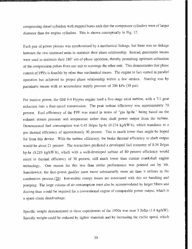
compressing diesel cylinders with stepped bores such that the compressor cylinders were of larger
diameter than the engine cylinders. This is shown conceptually in Fig. 17.
Each pair of power pistons was synchronized by a mechanical linkage, but there was no linkage
between the two siamesed units to maintain their phase relationship. Instead, pneumatic means
were used to maintain their 180° out-of-phase operation, thereby permitting optimum utilization
of the compression pulses from one unit to scavenge the other unit. This demonstrates that phase
control of FPEs is feasible by other than mechanical means. The engine in fact started in parallel
operation but achieved its proper phase relationship within a few strokes. Starting was by
pneumatic means with an accumulator supply pressure of 206 kPa (30 psi).
For tractive power, the GM 4-4 Hyprex engine used a five-stage axial turbine, with a 7:1 gear
reduction into a four-speed transmission. The peak turbine efficiency was approximately 70
percent. Fuel efficiency of the FPE was stated in terms of "gas hp-hr," being based on the
exhaust stream pressure and temperature rather than shaft power output from the turbine.
Demonstrated fuel consumption was 0.45 lb/gas hp-hr (0.274 kg/kW-h), which translates to a
gas thermal efficiency of approximately 30 percent. This is much lower than might be hoped
for from this device. With the turbine efficiency, the brake thermal efficiency to shaft output
would be about 21 percent. The researchers predicted a developed fuel economy of 0.36 lb/gas
hp-hr (0.219 kg/kW-h), which with a well-developed turbine of 80 percent efficiency would
result in thermal efficiency of 30 percent, still much lower than current crankshaft engine
technology. One reason for this less than stellar performance was pointed out by Mr.
Samolewicz: the free-piston gasifier must move substantially more air than it utilizes in the
combustion process.(26) Irreversible energy losses are associated with this air handling and
pumping. The large volume of air consumption must also be accommodated by larger filters and
ducting than would be required for a conventional engine of comparable power output, which is
a space claim disadvantage.
Specific weight demonstrated in these experiments of the 1950s was near 3 Ib/hp (1.8 kg/kW).
Specific weight could be reduced by lighter materials and by increasing the cyclic speed, which
30

8 % H *
■-
© a u cu c 61 cc
ex s o
v «S3
a) u a >-, X
o o
"3 .5 °s D ex .s '■S « Si
4
ex)
31
can be accomplished by greater boost, higher bounce pressures, and reduced reciprocating mass.
All of these are development challenges.
In the mid-1960s, free-piston gasifier research was carried on in Canada by the Free-Piston
Development Company and at the National Research Council of Canada.(26, 30) The unit
developed was considerably smaller than those of previous research, at about 65 gas hp (48 kW),
approaching appropriate size for hybrid APUs. Its weight and volume were 410 lb (186 kg) and
4.69 cu. ft. (133 L), respectively, without accessories. Without provision for a power turbine and
alternator, but assuming a gas-to-electric conversion efficiency of 75 percent, the specific weight
and volume work out to 5.1 kg/kW and 2.7 L/kW, respectively. Minimum specific fuel
consumption was approximately 0.45 lb/gas hp-hr, consistent with that developed by the GM
researchers. These numbers are not encouraging. The reciprocating speed was 2,015 cpm.
Further development of the system for higher speed and lighter weight could presumably improve
these numbers somewhat. Predictions by Wallace, et. al. (30) were that at high boost pressures
and turbine pressure ratio of 5 to 1, the FPE gas generator-turbine combination could achieve
overall brake thermal efficiency of 39.2 percent, still short of current diesel engines but
competitive with spark-ignition engines. At the higher cycle pressures and temperatures, NOx
emissions may become an issue.
More recent development of FPEs has focused on their use as dedicated gas compressors and
hydraulic pumps. As a hydraulic pump, the FPE could be used in hybrid vehicles in one of two
ways: hydraulic motors could be used for traction or for driving an electric generator. Since this
study focuses on the hybrid electric vehicle, the traction motor configuration will not be pursued
here but is well worth considering in the overall view of high efficiency vehicles. Under certain
conditions, hydraulic motors can have efficiencies on the order of 95 percent or better, well in
excess of that of state-of-the-art turbine expanders; therefore, the FPE-hydraulic
pump/motor/generator combination is an attractive alternative to the FPE gas generator.
Research in Japan by Dr. A. Hibi of Toyohashi University has demonstrated several aspects of
the FPE hydraulic pump.(31, 32) Their solution to the problem of poor turndown is to
intermittently cycle the engine, with a dead period between cycles. In demonstration testing, the
32
reported overall thermal efficiency of their device is poor at 14.3 percent; however, they
demonstrated good conversion of indicated gas power to hydraulic power at an efficiency of 84
percent, including losses to drive a scavenging pump. The poor thermal efficiency can be
attributed to the use of a motorcycle-type carbureted two-stroke cycle, with inherent losses of
unburned fuel-air mixture during scavenging. In a later publication, Dr. Hibi suggested an
attainable overall thermal efficiency of 41 percent; however, his assumption of 50 percent
indicated thermal efficiency for the combustion process is optimistic.(33)
The FPE hydraulic pump, with a spark-ignited combustion system, was studied analytically by
P.C. Baruah.(34) A fairly comprehensive first-principles thermodynamic simulation was used,
including the effects of flame speed on combustion rates. However, the analysis omitted the gas
exchange effects, which may be significant. In comparison with a conventional crank engine,
this study pointed out one reason why the thermal efficiency of the FPE may not reach its full
perceived potential. The reversal of the piston at top dead center is controlled entirely by the
dynamics of the spring mass system. Upon commencement of combustion, the piston undergoes
rapid acceleration toward the load end of the engine and achieves substantially higher velocities
during the expansion stroke. The timing of combustion is less flexible than with conventional
engines and must take into consideration the need to appropriately control compression ratio.
As a consequence, the combustion process tends to occur over a greater proportion of the
expansion stroke, in terms of volume, not time. Thus, the thermal energy of combustion is used
less effectively. To overcome this problem, FPEs would have to achieve higher rates of
combustion. One advantage of later combustion, as pointed out by Mr. Baruah, is lower NOx
emissions.
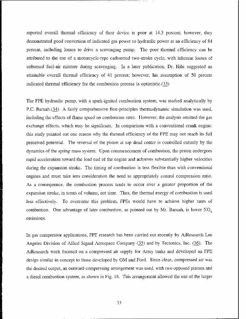
In gas compressor applications, FPE research has been carried out recently by AiResearch Los
Angeles Division of Allied Signal Aerospace Company (35) and by Tectonics, Inc. (36). The
AiResearch work focused on a compressed air supply for Army tanks and developed an FPE
design similar in concept to those developed by GM and Ford. Since clean, compressed air was
the desired output, an outward-compressing arrangement was used, with two opposed pistons and
a diesel combustion system, as shown in Fig. 18. This arrangement allowed the use of the larger
33
ENGIWE LUBRICANT ENGIWE COOLANT
INLEi AIR
ENGINE "^EXHAUST
i START TANK j RECHARGE
"""A AIR
1. Diesel cylinder 2. Fuel injector and synchronizing mechanism
3. Diesel cylinder exhaust port 4. Diesel cylinder scavenge port 5. Diesel cylinder cooling jacket S. Bounce cylinder 7. Compressor cylinder with read valves
8. Coolant pump 9. Coolant radiator and cooling air fan
10. Turbocharger
11. Start tank 12. Start valves
Figure 18. Conceptual design of AiResearcfa Mark II free-piston compressor
34
bore to supply air both for scavenging and for the output. The best obtained indicated specific
fuel consumption of this unit was 0.388 lb/hp-hr (0.236 kg/kW-h), based on the power cylinder
indicator diagram. However, based on the compressed air output, specific fuel consumption was
0.621 lb/hp-hr (0.378 kg/kW-h), representing thermal efficiency of approximately 22 percent.
About half the difference between "indicated" and "brake" output can be attributed to mechanical
friction and half to the portion of the compressed airstream diverted to scavenge the engine.
Some of this pumping loss could presumably be averted by rearranging the valving and porting
such that the scavenging air is diverted at the desired pressure, not first pumped to the
compressor output pressure. Thermal efficiency of 25 to 28 percent might be attainable by using
this arrangement.
Tectonics, Inc. was engaged in the development of FPEs for dedicated air and gas compressors
before the company dissolved in 1993. SwRI was contracted with Tectonics for the design and
development of their FPE compressors. The units designed by Tectonics were targeted for
stationary applications and were not designed for compactness or weight. A single,
conventionally scavenged two-stroke SI natural gas engine cylinder was used for the power unit,
driving a conventional single- or multistage compressor cylinder with a rack-and-pinion-driven
counterweight for balance. In tests at SwRI laboratories, these units achieved about 23 to 24
percent gas thermal efficiency. Inefficiencies were attributed to incomplete combustion,
scavenging losses, heat transfer, and friction primarily in the ringpacks, which were not optimally
designed.
The key to achieving high power density in FPEs is high cyclic speed. It has been reported that
Mr. Frank Stelzer of Germany has designed a free-piston engine capable of cyclic speeds on the
order of 30,000 cpm.(37, 38) This is achieved by employing two opposed combustion chambers
driving both sides of the piston, such that the bounce pressure is the combustion pressure. The
claim of 30,000 cpm seems doubtful, but it is likely that cyclic speeds could be boosted
substantially by this approach. The limit to reciprocating speed will most likely be ring wear.
There are several possibilities for applying FPE technology to a hybrid APU. These are
discussed as separate engine concepts.
35

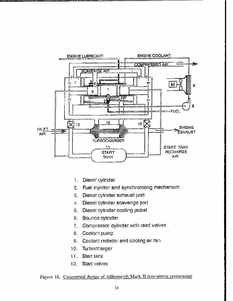
a. Free-Piston Engine With Linear Generator (FPELG)
An approach to power production is to provide a linear electric generator at the "bounce" end of
the cylinder. The concept is shown schematically in Fig. 19. This generator will convert the
kinetic energy of the piston directly to electric current, slowing the piston motion in the process.
SwRI, in partnership with The University of Texas Center for Electromechanics (UTCEM) and
sponsored by ARPA, has investigated the possible design configurations for a linear alternator
and developed a design concept that integrates nicely with the FPE and has high predicted
efficiencies.(39) The elements of the generator include an iron core with an air gap, an excitation
coil, a generator coil, and the lower edge of the piston skirt. Magnetic flux is induced in the
iron core by the excitation coil. As the piston skirt passes through the air gap, it alters the shape
of the magnetic field, inducing current in the generator coil. This concept is mechanically simple
in that the only moving part is the piston itself, and there is no requirement for electrical contact
to the piston. For this reason, mechanical losses should be extremely low. The nature of the
device is such that current is only generated during the expansion stroke of the cycle, and the
power generation during expansion also exerts a restoring force on the piston, helping to slow
its travel toward the bottom end. Gas bounce is necessary to achieve the next compression
stroke. A test is currently underway at SwRI to demonstrate the highest risk element of this
concept, the generator.
Preliminary design of the SwRI-UTCEM FPELG focused on a demonstrator unit of
approximately 6-in. bore and stroke, based on the Tectonics engine unit. Design calculations
indicated that this concept could achieve a peak thermal efficiency of approximately 30 percent,
including generator losses. The demonstrator unit was not packaged for minimum weight;
however, power-to-weight ratios of about 2.5 kg/kW are probably achievable. The demonstrator
represents a specific volume of about 2.8 L/kW, and with development, the level of 1.8 L/kW
is probably achievable, including power electronics.
Cost, reliability, and producibility should be much better than with conventional engine-generator
configurations because of the tight integration of the system and the single moving part.
36
Cranksh
CyI i nder
Adapter Plate
Copper Ring Steel Housing
Central Shaft
Copper Co i I
Figure 19. Linear generator for free-piston engine in rig testing configuration
37
Emissions issues are the same as with conventional two-stroke engines. There is great technical
risk associated with this technology, as the generator concept is unproven and the integration of
the engine with the generator presents challenges. Using two opposed units, there are no
unbalanced reactions, so NVH should be better than with conventional engines; however, exhaust
and intake pulsations will have to be dealt with. Multifuel capability is a bonus for the FPE,
since its compression ratio can be adjusted to suit the fuel used. Transient response is excellent,
as the engine reaches its operating speed instantaneously. This is also reflected in startability;
for a properly designed system, starting is accomplished with a single impulse from either the
electromagnetic system of the generator or a compressed air bottle attached to the bounce
chamber.
b. Free-Piston Gas Generator With Turboalternator
Another option for using the FPE technology is to update the technology of the 1950s and 1960s
by routing the exhaust gas to a turboalternator. The FPE technology for gas generators is fairly
well developed, if somewhat obsolete. Updates of this technology could be expected to achieve
overall specific fuel consumption of 0.48 kg/kW-h, including 0.35 kg/gas kW-h for the gas
generator, turbine efficiency of 80 percent, and generator efficiency of 92 percent. This translates
to a thermal efficiency of roughly 17 percent. Gains would be made in specific power and
weight owing to the high speed generator. Gas generator specific volume could be around
2.0 L/kW and specific weight about 1.5 kg/kW, if developed specifically for these criteria.
Cost of the turboalternator may be somewhat higher than the cost of the linear generator plus
power electronics required in the previous concept; in addition, the FPE is somewhat larger and
more expensive because a stepped bore and valving are needed for the compressor cylinder.
Emissions again are equivalent to the two-stroke engine. Producibility is probably equivalent to
the conventional four-stroke engine, gains of the FPE compensated by complexity of the
turboalternator. Reliability should be somewhat better than conventional engines, as there are
fewer moving parts, and the turbine does not see high exhaust temperatures. The technical risk
is relatively low, as each component has been fairly well developed. With a balanced FPE, the
noise and vibration characteristics should be even better than the FPELG because the turbine will
38

serve to muffle exhaust noise. Multifuel capability is the equivalent of the FPELG. Transient
response is not as good as with the FPELG, or even with conventional engines, because of the
lag of the turboalternator. However, startability is as good, relying upon a compressed air supply.
The compressed air can come from a bottle and can be stored during system operation.
2. Rotating Combustion Chamber Engine
In 1993, SwRI contracted with Mr. Ross Riney to evaluate his concept of a rotary engine.(40)
The essence of the concept includes separate compression and expansion rotors on a common
crankshaft, with a combustion chamber attached to a third rotor on a shaft rotating at one-half
crank speed at right angles to the crankshaft. This is illustrated in Fig. 20. Floating vanes riding
on the rotors divide the compression and expansion housings into two chambers, allowing for
intake and compression processes to occur simultaneously in the compression rotor, and
expansion and exhaust processes to occur simultaneously in the expansion rotor. The air charge
Figure 20. Rotating combustion chamber engine
39

is transferred from the compression stroke to the combustion chamber and subsequently to the
expansion chamber through ports that are timed by the rotating combustion chamber, which also
serves as a rotary valve.
The study done by SwRI utilized thermodynamic cycle simulation to examine the invention and
determine its potential as an alternative power plant. The study found that its significant
advantages were as follows:
° Separate compression and expansion rotors allow the expansion ratio to be substantially
higher than the compression ratio, permitting more complete utilization of the heat
energy.
° Port timings can be arbitrarily established to optimize the gas exchange processes.
° Constant or near-constant volume combustion can be achieved by port timing.
° The duration at constant volume can be tailored to the combustion process.
° Perfect balance assures that the engine can operate at high speed.
0 The engine achieves a power stroke on every revolution while retaining the benefits of
a four-stroke cycle.
While these benefits are important, there are also some significant technical risks:
° The sealing challenge is more significant than for the Wankel engine because of a
large number of sealing surfaces. lo"-
° The seal between the rotor and housing depends upon close tolerances and cannot
permit a floating seal member because of the need to pass under a floating vane.
40

• The separate expansion rotor will be highly thermally loaded.
• The dynamics of the floating vanes may limit speed.
• The gas exchange process also limits the speed at which good efficiency can be
maintained.
The SwRI study only investigated the thermodynamic cycle and did not address sealing,
lubrication, or cooling issues, which are the significant technical challenges. While the study
predicted power density to be substantially higher than for conventional automotive engines, the
thermal efficiency was predicted to be lower, owing primarily to large amounts of heat transfer
due to large surface area. This concept is attractive because of its potential for high power
density at high shaft speed; however, it is also extremely high risk at its current conceptual stage.
Working prototypes have not been built.
Based on the estimates of SwRI's study, the engine would have specific volume of about
1.5 L/kW and specific weight of about 1.2 kg/kW. At a rated speed of 10,000 rpm, the
corresponding generator would have specific volume at roughly 0.22 L/kW and weight of about
0.8 kg/kW. Thermal efficiency of around 19 percent was predicted for the engine, for an overall
system efficiency of 17.5 percent. Cost of the engine may be fairly high because of high-
temperature materials requirements. Emissions should be equivalent to the four-stroke engines.
Producibility and reliability would be questionable due to expensive materials and hot
environment of the combustion chamber and expansion rotor. This concept has very high
technical risk. NVH should be well controlled due to good balance. Multifuel capability is
equivalent to SI engines, and transient response should be fairly good due to low inertia. Starting
may be difficult because of the high leakages around the large sealing surfaces and resulting poor
compression at low speed.
41
3. HCCI Engine With Pressure Relief
Homogeneous Charge Compression Ignition (HCCI) is an unconventional combustion process
wherein a premixed charge of fuel and air is ignited by compressing it to the point of
autoignition. It is similar in many respects to detonation or knock, the uncontrolled combustion
that can damage or destroy SI engines. However, it differs in that an engine designed for HCCI
does not necessarily initiate combustion by a spark and does not experience the travel of a flame
through the mixture, compressing the unburned charge to the point of detonation. Nor is HCCI
generally initiated at hot surfaces of the combustion chamber, as is knock. Rather, the ignition
is initiated at a multitude of points within the combustion chamber volume by the presence of
active radicals, or combustion precursors. Combustion progresses rapidly and consumes the
entire mixture within a short period of time. The intense combustion process has discouraged
most researchers from pursuing HCCI as a feasible commercial process; however, if a means of
dealing with the extreme rates of pressure rise can be devised, there are many benefits to be
gained from HCCI.
Evan Guy Enterprises, Inc., of San Antonio, Texas, has demonstrated a small two-cylinder engine
with several unique features devised to take advantage of HCCI for the combustion of heavy
distillate fuel. The engine is targeted at the UAV application and operates on a two-stroke cycle.
The key feature of the engine is a proprietary cylinder head device designed to soften the
combustion process by limiting the peak pressure. Energy is stored mechanically during the
combustion process and returned to the cylinder during the expansion stroke for useful work.
The engine has been successfully demonstrated burning several fuels, including diesel, JP-8, and
gasoline. Its efficiency is relatively high as a result of high effective compression ratio and an
effective combustion process, which works well with lean mixtures. Durability problems
encountered in early designs have largely been solved.
Based on the limited test data obtained to date, the developed engine has predicted fuel
consumption of 0.3 kg/kW-h, for a brake thermal efficiency of 0.275. Its operating speed is
relatively high at 6,000 rpm, which will lead to compact generator configuration. The expected
specific weight and volume of a developed engine are LI kg/kW and 2.1 L/kW, respectively.
42
The cost should be advantaged relative to conventional four-stroke engines. In its current
configuration, the engine admits a premixed fuel-air charge, so it is subject to emissions problems
due to scavenging losses. However, direct injection is an ultimate goal, so emissions should be
better than for direct-injected SI two-strokes owing to the clean combustion process. A particular
emissions benefit results if the HCCI process can be used to take advantage of the low NOx
possible with extremely lean mixtures, a strong possibility with this engine. Producibility should
be good, but obtaining automotive class reliability will require significant development. Noise
characteristics should be comparable to competing two-stroke engines. The multifuel capability
is very good with volatile fuels but dependent upon preheating of the fuel when running with
diesel or other heavy fuels. Transient response is good; however, because of the required fuel
preheating, startability is not as good. This should be considered a high risk option since the
technology is in early development stages.
4. High-Speed Detonation Engine
It has been observed in the racing industry that engines running at very high crankshaft speed
(13,000 to 15,000 rpm) are relatively insensitive to fuel octane rating. Despite high compression
ratios, they do not suffer from knock problems, and they are not adversely affected by fuels of
octane ratings that would be intolerable in engines of similar compression ratio at conventional
speeds. The explanation is that at these high speeds, the expansion process is so fast that the gas
is expanded before significant pressure excursions can occur. The combustion process is largely
a detonation process, similar to HCCI, but no component damage is encountered because of the
rapid expansion. Since high speed is also desired for the generator of an APU, this approach to
the engine and combustion system may be of interest for the APU system.
The chief advantage of the high-speed detonation engine (HSDE) over conventional technology
is high power density owing to high crankshaft speed. The disadvantages are several, including
durability, thermal efficiency due to high friction, noise, and risk. Scores for the high-speed
detonation engine are based on a three-cylinder engine of 60-mm bore and 50-mm stroke, for a
total displacement of 0.43 L, running at 13,000 rpm. Cycle simulation predictions with this
engine indicate that it could produce 30 kW-h assuming a generator efficiency of 92 percent.
43

Predicted thermal efficiency of the engine was 24.6 percent, lower than conventional four-stroke
engines primarily because of friction and pumping losses at high speed. With generator, a
thermal efficiency of 22.6 percent is predicted. The engine could be packaged with a specific
volume of about 1.75 L/kW and specific weight of 0.7 kg/kW, assuming weight scales with
volume from conventional engines.
Cost of the HSDE should be comparable or slightly higher than a conventional four-stroke
engine. Emissions should also be comparable or slightly worse, as alteration of valve events to
achieve good volumetric efficiency at high speed may cause increased hydrocarbon emissions.
Producibility will be similar, but reliability will be markedly worse. This is a high risk option,
since the technologies are currently only used in racing engines that do not have to meet cost and
durability constraints. Noise would be worse than with conventional technology. The multifuel
capability would be slightly better than with conventional SI engines, since the octane
requirements would be reduced. Transient response should be fairly good, although it may take
the engine longer to reach the high speeds at which it is designed to operate. Startability will
be limited by high compression ratios, requiring relatively high cranking torque.
Model Airplane Engi
Another type of engine which utilizes a homogeneous compression-ignition type combustion
system are the small engines used for model airplanes. These engines typically run at very high
rpm enabled by small displacement, short stroke, and low reciprocating mass, and use either
alcohol fuel or diesel fuel heavily doped with additives to control knock and assure stable
combustion. They are attractive from the standpoint of high power-to-weight ratio and high shaft
speed, but currently only exist in small power ratings, generally of 10 kW and below. Two
possibilities exist to use this technology for hybrid APUs: 1) develop a multicylinder engine with
enough cylinders to make 30 kW (roughly 12 to 15 cylinders would be needed), or 2) develop
a smaller APU and equip the vehicle with several model airplane engines to achieve the desired
power rating. The second option is intriguing because the individual package volume would be
small and several units could conceivably be distributed to various locations in the vehicle that
would otherwise be unutilized. It is also of interest because of a general need for small,
44
lightweight motor-generator units for applications other than hybrid vehicles, particularly for
military use. Hence, the scoring of this concept for the hybrid vehicle will be based on the
second option.
The key to success of these engines for hybrid APUs will be the development of a combustion
system that burns conventional fuels and that is nonpolluting. The model airplane engine is
typically a carbureted two-stroke, and thus unacceptable for vehicle emissions. Direct fuel
injection is difficult to accomplish in the scale required for the small cylinders; therefore, the
most likely option is a four-stroke engine. There are many model airplane four-stroke engines
currently in production, so the technology already exists, but the power density will suffer
somewhat in comparison with the two-strokes. To achieve conventional fuel compatibility, a
spark-ignited combustion system is the likely candidate, with gasoline or natural gas fuel. HCCI
might also be contemplated, at significant added risk.
Estimates for scoring are developed primarily from advertising information of model airplane
engine manufacturers. An engine power-to-weight ratio of 0.6 is probably achievable, along with
specific volume of 1 L/kW. Fuel consumption is likely to be significantly worse than for
automotive technology engines, as these engines typically use a rich fuel-air mixture; however,
an engine designed for the hybrid APU application could improve greatly upon the current fuel
consumption of this class of engine. BSFC is estimated at 0.35 kg/kW-h, resulting in thermal
efficiency of 24 percent. Assuming the engine turns at 10,000 rpm, the generator specific volume
and weight are estimated to be 0.22 L/kW and 0.86 kg/kW, respectively. Cost should be low in
mass production. Emissions are questionable and would require significant development work.
Producibility is good, but reliability would also require significant development, as model aircraft
engines are not currently designed for long life. This is a high risk option due to the immaturity
of the technology for this application. Noise is a significant issue for high rpm engines but can
be dealt with primarily by mufflers. Multifuel capability would be equivalent to conventional
SI engines. Transient response would be better because of low inertia, and cranking torque
should be low.
45

6„ Two-Stroke Gas Generator With Turboalteroator
As an option to the FPE gas generator driving a turboalternator, a fairly conventional two-stroke
engine could also serve as the gas generator. In this system configuration, the two-stroke engine
would provide shaft power to a compressor, which may be a rotating or reciprocating machine.
The compressor would boost the scavenging air for the two-stroke cycle to an elevated pressure,
where it would then pass through the engine. The exhaust of the engine would be routed to the
turboalternator. This concept is shown schematically in Fig. 21.
A cursory analysis of this concept was done using a cycle simulation program for externally
scavenged two-stroke engines, backpressuring the engine with an orifice restriction to represent
the turbine. Turbine power was calculated based on the developed pressure and temperature in
the exhaust manifold, assuming 80 percent efficiency. The engine was driving a compressor at
77 percent efficiency. This analysis determined that the appropriate flowrates for a 30-kW
Turbo-Alternator
Two-Stroke Gas Generator
Figure 21. Conceptual design of two-stroke gas generator/turboaiternator
46
generator could be achieved with a three-cylinder engine of about 0.8-L total displacement.
Thermal efficiency of the complete cycle was predicted to be 22 percent. This engine would
have a specific weight of around 1.2 kg/kW and specific volume of about 2.6 L/kW. Its scores
for specific weight and volume are not as good as for the conventional SI two-stroke engine
because to achieve the proper balance of airflow and pressure rise for the turboalternator, a lean-
burn engine condition was assumed. Also, the engine deals with a proportionally larger
volumetric flow of air than an equivalent sized conventional engine, so there is a penalty for the
air handling ducts and filters. It would benefit from the generator size and weight advantages
of high speed.
Cost for this system would be about the equivalent of a conventional four-stroke
engine/generator; cost advantages of the simple two-stroke engine would be offset by the added
cost of high speed turbomachinery. Emissions should be good, as a lean-burn combustion system
will lead to low NOx emissions. Producibility should be comparable with conventional two-
stroke engines, and reliability should be good, as the turbine inlet temperature is very low. There
is some technical risk associated with the development of an engine tailored to this application,
but the technologies are all fairly well developed. Noise should be better than with conventional
engines because of the noise suppression effects of the turbine. Multifuel capability is equivalent
to conventional engines. Transient response is somewhat worse than conventional engines
because of the turbine inertia. In starting, the ease of cranking the two-stroke engine may be
offset by the reliance upon the compressor for scavenging air.
7. Regenerative Internal Combustion Engine
SwRI maintains an interest in more advanced engine concepts, and has performed studies on a
number of concepts related to Stirling cycle engines. The promise of these ideas is increased
thermal efficiency and reduced emissions; however, they have always been associated with high
weight, volume, and cost penalties, as well as technical risk, and have not yet become viable
commercial products. One such concept was investigated in an internal research project in 1987
and has since been refined.(42) It has now been named the Regenerative Internal Combustion
Engine (RICE). A thermodynamic analysis of the engine cycle predicted an indicated thermal
47

efficiency of 44 percent. Indicated power of 84 kW was predicted from a single-working
cylinder engine of 0.8-L displacement. The analysis was based on no-loss flow conditions and
idealized timing of valve events; more realistic estimates would reduce the efficiency and power
output somewhat.
The RICE concept is illustrated in Fig. 22. Two cylinders are employed, one serving as the
compressor and one as the expander. A transfer valve controls flow out of the compressor and
into a regenerator volume, into which a matrix of heat absorbing material is placed. The purpose
of the regenerator is to recover thermal energy from the burned products after the expansion
event, transferring this energy to the compressed gas from the compressor prior to combustion.
Thus, a portion of the heat energy supplied to the gas before expansion comes from the previous
burned charge, reducing the amount of thermal input needed from combustion. Upon completion
of the expansion event, the burned charge is pumped back through the regenerator and out the
exhaust valve.
Figure 22. Conceptual design of regenerative internal combiastion engine
48
Accounting for realism in fluid flow losses, valve events, and dead volumes, as well as
mechanical friction, the brake thermal efficiency of this device may be as high as 33 percent.
An APU utilizing this concept would then have brake thermal efficiency of 30.4 percent. It is
difficult to predict weight and volume from a conceptual design, but it could be expected to be
heavier and bulkier than conventional engines for a given working displacement. The first
analysis, however, predicted a very high power density based on displacement. Accounting for
the realistic inefficiencies, the displacement of the working cylinder needed for a 30-kW power
plant is about 0.41 L, and the engine could be well represented by a two-cylinder engine of
0.82 L total displacement. This engine may be expected to have a weight of 50 kg and volume
of 82 L, giving specific weight and volume of 1.7 kg/kW and 2.7 L/kW, respectively. The
generator weight and volume would be the equivalent of conventional systems.
Cost will be relatively high, owing primarily to the regenerator, which will require high
temperature materials. Some development of the fuel injection and combustion system will be
needed to assure low emissions, and NOx emissions may be a problem due to preheating of the
air or air/fuel mixture. Producibility and reliability may be slightly worse than for conventional
engines, owing again to the regenerator. This is a relatively high technical risk approach. NVH
is probably better than for conventional engines, as the regenerator will serve to reduce exhaust
pulsation. Multifuel capability is unclear, as the combustion system is as yet unspecified, but is
probably better than conventional spark-ignited engines since the charge is preheated. The
transient response characteristics will be worse than for conventional engines, and starting will
be slow with the need to warm up the regenerator.
B. Subsystem Concepts
For the purpose of ranking the subsystem concepts, they are considered as applied to the baseline
engine, the four-stroke spark-ignited engine. Thus, they can be compared on an equivalent basis.
The scores are expressed as increments to the baseline. Most of the ideas are applicable to
several of the system concepts.
49

1. Electric Valves
A limitation to the speed and performance of conventional poppet-valved four-stroke engines is
the valvetrain, both in terms of valve dynamics limiting engine speed and fluid dynamics
producing pumping losses for flow into and out of the cylinders. Aura Systems, Inc. has patented
an electromagnetic valve actuation system which helps to overcome some of these limitations.(41)
Its claimed advantages are
0 elimination of the conventional valvetrain for reduced engine friction;
° low electric power consumption (53 W per valve on a 16-valve engine at 7,500 rpm);
° rapid valve actuation, achieving near square-wave valve motion; and
° variable, programmable valve timing.
With further development, the system could likely increase the speed capability of conventional
engines. Aura Systems predicts increased power by 10 to 20 percent, increased fuel economy
by 10 to 20 percent, and emissions improvement in comparison with conventional SI engines.
These predictions seem plausible if the system does mechanically what they claim. Even more
increase in power density could be achieved if the engine rated speed is increased. The
developed system cost in production is probably equivalent to a conventional valvetrain; the
added electromagnetic components and power electronics replace the conventional camshaft and
valvetrain components. NVH may be reduced by the elimination of valvetrain mechanical noise.
Transient response may also be improved by programmable valve timing. An automatic
compression release function could be programmed into the valves to aid in starting. There are
technical risks associated with this technology.
50

2. Stepwise Mixture Control and Turndown
Conventional emissions control in a SI engine depends upon a three-way catalyst and tight
control of fuel-air ratio around the stoichiometric condition. If the fuel-air ratio deviates far from
stoichiometric on either side, HC and CO or NOx emissions are adversely affected by poor
catalyst performance. However, if the engine is operated far enough to the lean side, NOx
emissions are again reduced by virtue of lower combustion temperatures. One approach to
emissions control is to operate the engine at stoichiometric fuel-air ratio for rated condition and
reduce power by a combination of throttling and lean mixture. If stepwise power transients are
desired, as is likely the case with a hybrid APU, this control mode is feasible; however, it is
probably not useful for a direct-drive vehicle. The advantages of this concept are improved part-
load fuel economy and emissions, which may or may not be a strong driver for the hybrid APU.
There are no other perceived advantages.
3. Step-Up Gearbox
To take advantage of the reduced weight and size associated with generators running at high shaft
speed, one approach is simply to employ a step-up gearbox. The tradeoffs of this approach are
increased size, weight, cost, and reduced efficiency associated with the gearbox, with reduced
size and weight of the generator. This idea is applicable to any crankshaft engine. Estimates for
the relative effects of incorporating this idea are based on the assumption of a 4:1 step-up gear
ratio to achieve 24,000 rpm with the engine speed at 6,000 rpm. The gearbox for this application
would likely be a two-step geartrain with 2 to 1 ratios on both gear sets. Its weight and volume
would be about 20 kg and 12 L, respectively. The torque losses would be about 3 percent,
resulting in an effective generator efficiency of 89 percent. Slight penalties would be incurred
in system cost, noise, startability, and transient response.
51

4. Step-Up Gearbox Integrated With Crank
To limit the penalties associated with a step-up gearbox, an engine could be designed to
incorporate the features of the gearbox into the crankshaft system, thus reducing somewhat the
weight, volume, and cost penalties. Other effects on system characteristics would be unchanged.
:ure A urooenargämg
Proponents of turbocharging have long recognized the importance of exhaust system pressure
pulsations in the performance of the turbine. Pulse effects are often credited for improvements
in turbine efficiency on the order of 10 to 30 percent, and "effective" efficiency values based on
mean exhaust manifold conditions are often greater than one. Recognizing that a typical
reciprocating engine wastes a significant proportion of the exhaust gas energy in the process of
blowing down the cylinder from its final expansion pressure to the manifold pressure, SwRI
engineers have theorized a means of capturing this otherwise wasted energy. The concept is to
utilize separate exhaust valves for the blowdown process and for the exhaust stroke, capturing
the higher pressure exhaust products in a separate manifold and achieving higher availability of
exhaust energy for work in the turbine. An additional feature of the concept is the use of
acoustic elements in the blowdown manifold to further enhance the recovery of blowdown
energy. While this concept primarily benefits large, highly turbocharged engines, it also has
potential applications to the APU.
One possibility for application to hybrid APUs is to simply highly turbocharge a conventional
engine. This could result in improvements in power densities on the order of 30 to 50 percent
over the naturally aspirated engine; however, turbocharging is difficult for smaller engines. Fuel
economy would also be improved. The improvement attributable to blowdown capture is unclear
without further study but could be on the order of 10 percent in power density and 5 percent in
fuel economy. Another option would be to take an otherwise naturally aspirated engine and
capture the blowdown pulses in a separate manifold, routing them to a turboalternator. This
would be of special interest in parallel drivetrains where the shaft power of the engine would be
used for direct drive and the turbine power for charging the batteries. Further investigation is
52
perhaps merited for this option but outside the scope of consideration in this study. Risks
associated with the idea are primarily to the durability of the turbine, which will be exposed to
higher temperature air.
For the purposes of ranking in this study, the application to the conventional turbocharged engine
is assumed, with the benefits noted above. The applicability of the concept depends upon
whether a turbocharged engine is indicated, which is highly dependent upon the required power
rating. For smaller vehicles, turbocharging is probably not a reasonable option because of the
unavailability of commercial turbochargers in an appropriate size. However, for power ratings
of 50 kW or above, turbocharging is a possibility.
6. Combined Cycle Heat Recovery
The primary source of wasted energy in an internal combustion engine is thermal energy in the
exhaust system. For SI engines, this energy is of relatively high quality (high temperature) and
could be utilized in a combined cycle, similar to cogeneration. This option, referred to as a
"bottoming cycle," has been studied by several researchers.(43-46) The technologies to do this
include Rankine cycle machines, Brayton cycle machines and Stirling engines, as well as other
possibilities. The technologies are not well developed for automotive prime movers and are
likely to have significant cost, weight, and volume penalties. Estimates made by one study
indicated a potential improvement of about 15 percent in fuel economy at rated conditions for
a baseline diesel engine.(43) Volume and weight penalties were not given, but it is assumed for
this study that the additional equipment would require about 50 percent of the baseline engine
volume, weight, and cost.
VII. DISCUSSION OF CONCEPT RANKING
The comparison analysis of APU system concepts is summarized in TABLE 1. This table
presents the raw scores on each of eleven criteria, the calculation of scoring statistics to establish
53
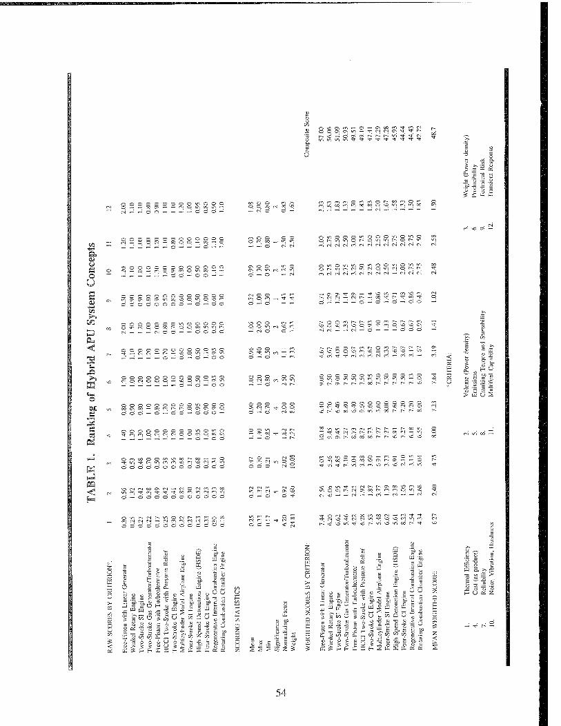
O ^) C\ m - O — CNOOCfi O O CJN CN O — 'I' M CN C> t—; vo —■i o ON CN r- r- r~~ o Tt TJ- CN
t t -t
0000000000000 q q co o)
O O — —
<-<-] <•«-> o n
OOOOOOOOOOOOO (M-oorJ«wqq-oo-^q rJ co - m vi
—'■ ö CN CN
o o o o o ■ o t— o „ , -.-.— - - o **"> ■
m (vi W IN M (N N d M' N CN (N oi
m \o (? -
©
OOOOOOOOOOOOO ^„o— — — — ——■■-.«« — — ON OO
—; ö O O CO cr\ m o cN ^ W"J
O — Ö «-- <N
0000000000000 or^or— cNocNoocNor-^r--; rtrJcJrirnrJriiNN-M'iNN
OOOOOOOOOOOOO
OOOOOOOOOOOOO oocNOOoor~-""'",,~'^'''^
o ro _ -d- -*■ — d — ~
u-i ^ ^O cn d d —
oo *■* r- *^ co -^j- o o -J d ™ d d —'
r- en O r*~i r-- r- r- ci — OCN*3-mONO\DCN -* ^0'_:_-;_ödd —'
0000000000000
d —'• — o — o o ON TT >n m
oor-c-ir-Ocii— r^r— r- OOOCI^OOCi^p^O — MD ■t t' <*i oi en ei r! - ri n -
~ Q»
IS S3
00000000000*00 CN O CN O O O — vqoio—i C; V;
ooooooooo«nooo ._ _ — — -■ — — o OS CN CN p
OOOOOOOOOOOOO TJ- c*-) C-IOCNCNCNOOCNOCOON
„■_;_;_:_;—"—' — -: d — d d
— — o
ON N Is; ^ q q
— T CO —" — d
OOOOOOOOOOOOO OOOOOOCNOOOO--O
OOOOOOOOOOOOO O VC NO
^D CO VO ON O O VO CN CN o oo r^ S r~ oo
;m or— comenr-r- — r— co o !-3-"3-cNr-;r~-r-cNcNONCN — o ;CNO\r^ocododr-;r^^dr^vd,o
Ü S
CN O CO
OmoooOoosOoor-oo-~ — O t in T h m n (*) vo rn ^q « (*; ^. odddoododdded
cnvOOO-tf-ooO—- ro — O o -3- Omoo — OoovqONr-;ON—; —; p
f==l
VDCNCNOOONtN*— fNOCMr^.noo
ö •—' o d o d d d d d d d d
CN CN m CN O m Ci N IT, C> O d —: d d rf
vO^O-^-0)(Nr-C~-ONOOOr~lco moONf-cNCNOor-^firooovq PJ ^ __; _; f-sj — -^ r-i — cN —' — CN
Oor-cNt--oo<Nr--tr>n-io00
mCNCNCN—' CN c~. CN CN CN c"l (T-, —< do'dddddodddod
OCN\CCNOOO"lCOCN—'CN*3"Tf CNvD-rfCNCNOTf\OOCNOm ovOOTTvor^o'^docor^*^"
3= < OS
tÜ CO o
^ ^ ei X — ^
OS b
a -^
S •; >• rrr ,5 ~ i t"! OS
8 I
£Z c- ^— UJ n ^ on
^ o
S
< c c
Ü c
U U
o tyN
(■)
o Ü-i
S UJ o S <
o ;> U >- on u U PI 5
O 5 o
o
-o o
-a
c
> OD z
on G. t/J u u' s ._ tY.
o o
o o
"cb o
DO O
o u
z o
u >-
re £ c -
S H H £ S H I t, OS OS
c "N H
D •JJ ^ m 4d p "cb o DC o
2 ^ U4
Q DO Zi
W "5)
'S DO £ o
c« i>p a. —, w 6 i ü U o 5 > u U >
ü ä >.£ tu •= "i = > OS H ^s- IS nl-
o " d ~ o
s on Q U
c ■S
>■> m c n '■5 u %
r/^ on on £ A> <'
3 =3 DU n> o UJ
^ U- X Ä cc -c
54

final weighting, and the weighted scores. Composite scores at the right of the table are the sum
of weighted scores for all criteria. The concepts are ranked in order of their score, from highest
to lowest. The mean weighted score is provided as a means of evaluating the general merit of
a concept.
The highest scoring concept was the free-piston engine linear generator (FPELG). The primary
contributors to this ranking were perceived advantages in thermal efficiency, cost, producibility,
reliability, NVH, fuel tolerance, and transient response. It is less attractive from the standpoints
of power density and risk; however, it still ranks ahead of the baseline four-stroke SI engine in
the power density categories. It should be noted that the power density of the FPELG is still
unknown and could be grossly overestimated, hence the technical risk. This concept certainly
merits detailed investigation.
The next highest ranked concept is the Wankel rotary engine. By contrast with the FPELG, its
advantages are primarily in the area of power density and risk, with lesser (but still substantial)
benefits in terms of cost and NVH. The Wankel engine is well-established and offers a low risk
alternative for advanced high power-density APUs.
These top two concepts were very closely ranked. Considering the subjectiveness of this
analysis, their order of ranking should be considered interchangeable. By contrast, the next
highest ranked concept, the two-stroke SI engine, scored significantly lower. It scored well in
the categories of thermal efficiency, cost, producibility, reliability, and risk. Interestingly, it did
not score as well in power density. Although the two-stroke engine has been touted as a high
power-density alternative, its advantages are weakened by the need to consider the weight of a
generator in the system. The two-stroke engine has some advantages in the respect that it can
run at higher rpm than a conventional engine; however, the Wankel engine is even better at
achieving high power in a small package.
The combination of a two-stroke gas generator with a turboalternator scored fairly well, primarily
owing to a high power-to-weight ratio and a fairly well developed state of technology for the
55

BS.S Tii~Bi.'irftr*i1
system components. It is disadvantaged with respect to thermal efficiency, cost, and volumetric
power density, the latter attributable to the large air handling requirement.
The free-piston engine/turboalternator combination scored about 1.4 points below the
conventional two-stroke engine gas generator with turboalternator. This lower score is attributed
to lower thermal efficiency, weight power density, and emissions. The emissions difference is
debatable and is based on the presumption of a lean-burn cycle for the conventional crank-driven
two-stroke. The lean-burn conditions could also be applied to the free-piston engine, making its
score equivalent to the crank engine. Both options should be investigated further to better
quantify the differences, particularly in power density.
The HCCI two-stroke engine with pressure relief scored ahead of the mean overall but is seen
as a high risk approach. It has the potential of low cost, good thermal efficiency, and inherently
low NOx emissions. Its score is very close to that of the FPE-turboalternator, suggesting that
further investigation is also warranted.
The composite scores of remaining concepts were below the average. Many of these ideas are
good in one or two respects but suffer in one or several key areas needed to achieve the overall
goals of a hybrid APU. The primary discriminators are thermal efficiency and power density.
The scoring summary for the auxiliary concepts is shown in TABLE 2. For these ideas, the
composite score represents the overall ability to improve over the state-of-the-art for the hybrid
application. Only two of the six concepts scored positive: electric valves and stepwise mixture
control. The potential benefits of electric valves are strong; their main drawback is technical risk.
The stepwise mixture control approach can be implemented by a control system strategy, without
additional cost. Therefore, it offers a low risk technique for improved emissions and thermal
efficiency.
56
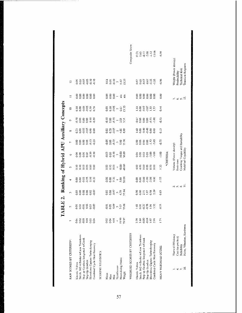
CO
£ "1
G\ r- oo <N S, t- o — "°. o N ^' 2 9
U
'* £
o ö o o o o 3t: un o [-. ° o —: CN ^ O ö O \o
r» r- en m ^o ^D m ro O o -^ —' £ £
o o o o o o — o o o o o o ■"" ö ö ö ö d> d>
o o o — ■ o o o o o o o o o o o o ö c ö d ö ö m \o C\ —■
a v u e o U
u .2 "R s
EU <!
"C
EC o en s s
pa
o — o P P — —
9 ö ö © 9 9
o © o o o © © © Ö © © ©
© o © © o © o © © © —: —: 000099
o © © © © ©
© © © ©
f-j © CO ^O CN OOO©© © © © Ö ©
■OQ-ffnS
— © O '
m © jp O — P O © 9
= o * o 0 9 en ro
£ O o © o ^ Pop
1 en P iri
O © ©
VD o O O § CM ©
o ^ ^r © P 0 9 ^ 8
■r in o^
o © _' _:
9 © © © 9 "7
o © —«
00©© o © © © © © 0" 0
© o o o o © © © © P d 0 0 d <?
© © © o © o 000000 Tf -T © d © ©
s s
© © — r- 00 £} cri o Is- 00 in n
H O
■355 = >UUS
oj m co —
P o o -a- t 5.
Z o
o u § 5 ° o
< ü m w w w en u
u CO
< f- co O Z
o u
QC f~ U > cu CO
C£ 1) 0 ( I CO iu n > ■*
LÜ > 0 S z
E &£ s s •& o
a 1 3 -->
tu « w w a U
o o
3; o s z <
S o "3 o P U OS Z
— ^r c^ —
57

VIII. RECOMMENDATIONS
All of these concept scorings and rankings are subject to substantial error. Many of the concepts
have only been subjected to cursory evaluation and limited analysis, whereas others represent
near production-ready technology. This is reflected in the risk scores. It should be borne in
mind that the evaluation is highly subjective in nature and could have a different outcome if a
different person was doing the analysis. Nonetheless, it is believed that these results present as
fair and unbiased an analysis as can be conducted in a study of this scope.
Bearing in mind the potential for error, it is recommended that these rankings be considered as
a screening test. SwRI recommends further study for the top six concepts. Although it appears
from this analysis that there are two concepts that clearly rank above the rest, these rankings may
change as more detailed information develops. The objective of this study will be to further
quantify and confirm their ranking relative to each other. This should be done in two steps as
follows:
1. Perform an in-depth cycle simulation study of each concept. The thermodynamic
cycle simulation can provide system-level comparisons of performance, fuel economy,
and emissions. This will directly refine the scoring in the categories of thermal
efficiency and emissions and will provide essential information on key component
dimensions to further quantify the power density. Thus, most of the higher
significance scoring factors will be refined. At the conclusion of this study, the
concepts should be reranked and the rankings studied to adjust downward those
concepts which are less competitive. This analysis can be done largely in parallel for
all six concepts but may concentrate on the top ranked concepts at first.
2. Perform a preliminary design analysis of each remaining concept to gain further
refinement of the volume and weight power density. This design analysis will consist
of layouts of all key engine and generator components using a CAD system that will
provide component mass properties for weight rollups. It will also include systems
analysis to assure that accounting is done for weight and size of necessary accessory
58
systems. At this point, the scoring estimates for volume and weight can be more
accurately determined.
At the conclusion of these analyses, it is likely that one or two concepts will emerge as meriting
full-scale development into prototype demonstration systems.
For the subsystem concepts, demonstration tests are the most useful means of further quantifying
their benefits. It is recommended that the top two concepts be considered for implementation
in demonstration test APU systems. Electric valves can be implemented in a conventional engine
to quantify their performance and emissions benefits. The lean turndown approach to achieving
fuel economy improvements in a four-stroke NG engine can be implemented by simply
modifying a control strategy. It can even be investigated by compiling existing data on engines
that can run at both stoichiometric and lean conditions and using these data in an appropriate
hybrid vehicle simulation.
This analysis has been very useful in establishing a framework for decision making regarding
choices of APU systems for hybrid vehicles. It is necessarily subjective but can be greatly
improved by the accumulation of more precise data on the comparison parameters. It is hoped
that ARPA finds this approach useful as well.
59

IX. LIST OF REFERENCES
1. Schneider, H.W., "Evaluation of Heat Engines for Hybrid Vehicle Application," JPL Publication 84-14, DOE/CS/54209-15, 31 August 1984.
2. Burke, A.F., "Hybrid/Electric Vehicle Design Options and Evaluations," SAE Paper No. 920447, February 1992.
3. Burke, A.F., and Smith, G.E., "Impact of Use-Pattern on the Design of Electric and Hybrid Vehicles," SAE Paper No. 810265, February 1981.
4. Burke, A.F., "On-Off Engine Operation for Hybrid Vehicles," SAE Paper No. 930042, 1993.
5. Gelman, D.J., and Perrot, T.L., "Advanced Fleat Engines for Range Extender Hybrid Vehicles," SAE Paper No. 930041, March 1993.
6. BVFLR Report
7. Amann, CA., "The Automotive Engine - A Future Perspective," SAE Paper No. 891666, 1989.
8. Fraidl, O.K., Quissek, F., and Winklhofer, E., "Improvement of LEV/ULEV Potential of Fuel-Efficient High Performance Engines," SAE Paper No. 920416, 1992.
9. Kreuter, P., Heuser, P., and Schebitz, ML, "Strategies to Improve Si-Engine Performance by Means of Variable Intake Lift, Timing and Duration," SAE Paper No. 920449, 1992.
10. Endres, H., Neuber, H.J., and Wurms, R., "Influence of Swirl and Tumble on Economy and Emissions of Multi Valve SI Engines," SAE Paper No. 920516.
11. Stock, D., and Bauder, R., "The New Audi 5-Cylinder Turbo Diesel Engine: The First Passenger Car Diesel Engine with Second Generation Direct Injection," SAE Paper No. 900648, February 1990.
12. Hundleby, G.E., "Development of a Poppet-Valved Two-Stroke Engine - The Flagship Concept," SAE Paper No. 900802, 1990.
13. Stokes, J., Hundleby, G.E., Lake, T.H., and Christie, M.J., "Development Experience of a Poppet-Valved Two-Stroke Flagship Engine," SAE Paper No. 920778, 1992.
14. Sato, K., Ukawa, H., and Nakano, M., "A Two-Stroke Cycle Gasoline Engine with Poppet Valves in the Cylinder Head - Part II," SAE Paper No. 920780, 1992.
15. Ukawa, H, Nakano, M., and Sato, K., "A Two-Stroke Cycle Engine with Poppet Valves in the Cylinder Head - Part III: An Application of Gaseous Fuel Direct Injection System," SAE Paper No. 930983, 1993.
60
16. Widener, S.K., and Swenson, K.R., "Two-Stroke Engines for Automotive Applications," Fourth Quarterly Report, SwRI Project No. 03-1464, March 1991.
17. Widener, S.K., Boyer, L., Gale, N.F., and Wood, CD., "A Heavy-Fueled Engine for Unmanned Aerial Vehicles - Design, Analysis and Prototype Demonstration," SAE Paper No. 950773, 1995.
18. Mount, R.E., and LaBouff, G.A., "Advanced Stratified Charge Rotary Engine Design," SAE Paper No. 890324, 1989.
19. Fujimoto, Y., Tatsutomi, Y., Ozeki, H., and Tadokoro, A., "Present and Prospective Technologies of Rotary Engine," SAE Paper No. 870446, 1987.
20. Tashima, S., Taqdokoro, T., Okimoto, H., and Niwa, Y., "Development of Sequential Twin Turbo System for Rotary Engine," SAE Paper No. 910624, 1991.
21. Mount, R., and Barrel, J., "Advanced Liquid-Cooled, Turbocharged and Intercooled Stratified Charge Rotary Engines for Aircraft," SAE Paper No. 871039, 1987.
22. Jones, C, "Stratified Charge Rotary Engine Developments at JDTI from 1984 to 1991," SAE Paper No. 920310, 1992.
23. Louthan, L., "Development of a Lightweight Heavy Fuel Rotary Engine," SAE Paper No. 930682, 1993.
24. "AR 731 Rotary Engine for Target Drones and UAVs", Technical Specifications from Alvis UAV Engines, Ltd., Lynn Lane, Shenstone, Lichfield WS 14 0DT, UK.
25. Pescara, R.P., "Motor Compressor Apparatus," U.S. Patent No. 1,657,641, 31 January 1928.
26. Samolewicz, J.J., "Experimental and Analytical Study of a Small Free-Piston Gasifier," ASME Paper No. 71-DGP-5, 1971.
27. Underwood, A.F., "The GMR 4-4 "Hyprex" Engine, A Concept of the Free-Piston Engine for Automotive Use," SAE Transactions, 65, 1957, pp. 377-391.
28. Flynn, Jr., G., "Observations on 25,000 Hours of Free-Piston Engine Operation," SAE Transactions, 65, 1957, pp. 508-515.
29. Frey, D.N., Klotsch, P., and Egli, A., "The Automotive Free-Piston-Turbine Engine," SAE Transactions, 65, 1957, pp. 628-634.
30. Wallace, F.J., Wright, E.J., and Campbell, J.S., "Future Development of Free-Piston Gasifier Turbine Combinations for Vehicle Traction," SAE Paper No. 660132, 1966.
31. Hibi, A., "Hydraulic Free-Piston Internal Combustion Engine," Power, April 1984, pp. 87- 91.
61

32. Hibi, A., and Kumagai, S., "Hydraulic Free-Piston Internal Combustion Engine - Test Result," Power, September 1984, pp. 244-249.
33. Hibi., A., and Hu, Y., "A Prime Mover Consists of a Free-Piston Internal Combustion Hydraulic Power Generator and an Hydraulic Motor," SAE Paper No. 930313, 1993.
34. Baruah, P.C., "A Free-Piston Engine Hydraulic Pump for an Automotive Propulsion System," SAE Paper No. 880658, 1988.
35. "Free-Piston Power Unit (FPPU) Integrated System Test Program," Final Report, 90-63865, Rev. A, AiResearch Los Angeles Division of Allied-Signal Aerospace Co., Contract DAAK70-89-C-0082, 22 February 1991.
36. Kubesh, J.T., and Meyer, R.C, "Evaluation of Tectonics Free-Piston Engine," Final Report for SwRI Project 03-4849, November 1992.
37. Stelzer, F., "Two-Stroke Internal Combustion Engine," US Patent No. 4,385,597.
38. Beachley, N.H., and Fronczak, F.J., "Design of a Free-Piston Engine-Pump," SAE Paper No. 921740, 1992.
39. Callahan, T., and Ingram, K., "Free-Piston Engine Linear Geneartor for Hybrid Vehicles Modeling Study," SwRI Draft Report for Project 02-5137.
40. Widener, S.K., "Concept Evaluation of a Rotating Combustion Chamber Engine," Final Report for SwRI Project 03-5221-004, May 1993.
41. "Proposal for Compact, Light Weight Natural Gas Fueled Electric Generator Using the Electromagnetic Valve Actuator/Rotary Actuator Motor Generator (EVA/RAMG)," Proposal by Aura Systems, Inc., to SwRI Belvoir Fuels and Lubricants Research Facility, 02 September 1993.
42. Thring, R.H., "Computer Analysis of the Open-Cycle Stirling Engine," Final Report for SwRI Internal Research Project No. 03-9459, March 1987.
43. Leising, C.J., Purohit, G.P., DeGrey, S.P., and Finegold, J.G., "Waste Heat Recovery in Truck Engines," SAE Paper No. 780686, 1978.
44. Sakono, T., Takizawa, S., Harada, S., Ikeda, T, and Abe, H., "Mazda New Lightweight and Compact V6 Engines," SAE Paper No. 920677, 1992.
45. Hiereth, H., Baehrens, W. E., Müller, W., and Withalm, G., "The Mercedes-Benz Group C Engines for the World Sports Prototype Racing Championships 1989 and 1990," SAE Paper No. 920674, 1992.
46. Ogata, Y., Shinbara, H., and Kimura, S., "Development of a Compact 3-Liter V6 Nissan Engine," SAE Paper No. 920672, 1992.
62
47. Foss, J.E., Jacques, R.L., Marsh, R.A., and Brooks, P.J., "The Northstar DOHC V-8 Engine for Cadillac," SAE Paper No. 920671, 1992.
48. Close, W.H., Fountain, G.H., and Daniel, M.R.L., "The New Collins Compact Scotch Yoke Engine," SAE Paper No. 920675, 1992.
49. SwRI Engine Database (A compilation of engine data from multiple sources).
50. Tsujita, M., Niino, S., Ishizuka, T., Kakinai, A., and Sato, Akihiko, "Advanced Fuel Economy in Hino New PI 1C Turbocharged and Charge-Cooled Heavy Duty Diesel Engine," SAE Paper No. 930272, 1993.
51. Stock, D., and Bauder, R., "The New Audi 5-Cylinder Turbo Diesel Engine: The First Passenger Car Diesel Engine with Second Generation Direct Injection," SAE Paper No. 900648, 1990.
52. Lawrence, R.J., and Evans, R.W., "The Ford 1.8L Four Cylinder Turbocharged Diesel Engine for Passenger Car Application," SAE Paper No. 901716, 1990.
53. Osake, N., Tsutsui, Y., Kakoi, Y., Sakino, Y., and Okazaki, K., "New Mitsubishi 2.8L Four- Cylinder Diesel Engine," SAE Paper No. 940587, 1994.
54. Duret, P., and Moreau, J.F., "Reduction of Pollutant Emissions of the IPAPC Two-Stroke Engine with Compressed Air Assisted Fuel Injection," SAE Paper No. 900801, 1990.
55. Blair, G.P., "Further Developments of a 500 cc Single Cylinder 2-Cycle Engine for Motorcycle Racing and Moto-Cross Applications," SAE Paper No. 740745, 1974.
56. Yamaoka, K., and Tado, H., "The Rotary Engines of Yanmar Outboard Motor," SAE Paper No. 710581, 1971.
57. Louthan, L., "Development of a Lightweight Heavy Fuel Rotary Engine," SAE Paper No. 930682, 1993.
58. Jones, C, "Stratified Charge Rotary Engine Developments at JDTI from 1984 to 1991," SAE Paper No. 920310, 1992.
63
APPENDIX
Database of Current Production and Research Engines
65
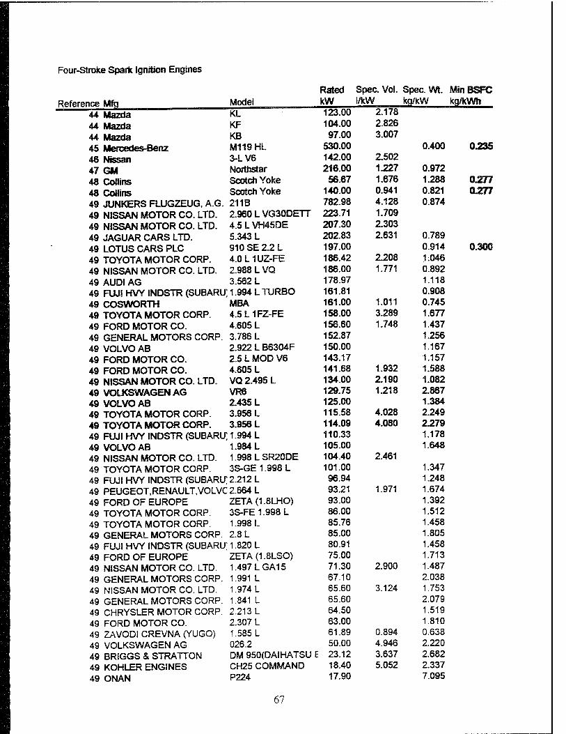
Four-Stroke Spark Ignition Engines
Rated Spec. Vol. Spec. Wt. MinBSFC Reference Mfg. Model kW 1/kW kg/kW kg/kWh 44 Mazda KL ~~ 123^5 2/178
44 Mazda KF 104.00 2.826 44 Mazda KB 97.00 3.007 45 Mercedes-Benz M119HL 530.00 0.400 023S 46 hfissan 3-L V6 142.00 2.502 47 GM Northstar 216.00 1.227 0.972 48 Collins Scotch Yoke 56.67 1.676 1.288 0.277 48 Collins Scotch Yoke 140.00 0.941 0.821 0.277 49 JUNKERS FLUGZEUG, A.G. 211B 782.98 4.128 0.874 49 NISSAN MOTOR CO. LTD. 2.960 L VG30DETT 223.71 1.709 49 NISSAN MOTOR CO. LTD. 4.5 L VH45DE 207.30 2.303 49 JAGUAR CARS LTD. 5.343 L 202.83 2.631 0.789 49 LOTUS CARS PLC 910SE2.2L 197.00 0.914 0.300 49 TOYOTA MOTOR CORP. 4.0L1UZ-FE 186.42 2.208 1:046 49 NISSAN MOTOR CO. LTD. 2.988 L VQ 186.00 1.771 0.892 49 AUDI AG 3.562 L 178.97 1.118 49 FUJI HVY INDSTR (SUBARU] 1.994 L TURBO 161.81 0.908 49 COSWORTH MBA 161.00 1.011 0.745 49 TOYOTA MOTOR CORP. 4.5L1FZ-FE 158.00 3.289 1.677 49 FORD MOTOR CO. 4.605 L 156.60 1.748 1.437 49 GENERAL MOTORS CORP. 3.786 L 152.87 1.256 49 VOLVO AB 2.922 L B6304F 150.00 1.167 49 FORD MOTOR CO. 2.5 L MOD V6 143.17 1.157 49 FORD MOTOR CO. 4.605 L 141.68 1.932 1.588 49 NISSAN MOTOR CO. LTD. VQ 2.495 L 134.00 2.190 1.082 49 VOLKSWAGEN AG VR6 129.75 1-218 2.867 49 VOLVO AB 2.435 L 125.00 1.384 49 TOYOTA MOTOR CORP. 3.956 L 115.58 4.028 2.249 49 TOYOTA MOTOR CORP. 3.956 L 114.09 4.080 2.279 49 FUJI HVY INDSTR (SUBARU] 1.994 L 110.33 1.178 49 VOLVO AB 1.984 L 105.00 1.648 49 NISSAN MOTOR CO. LTD. 1.998 L SR20DE 104.40 2.461 49 TOYOTA MOTOR CORP. 3S-GE 1.998 L 101.00 1.347 49 FUJI HVY INDSTR (SUBARU] 2.212 L 96.94 1.248 49 PEUGEOT,RENAULT,VOLVC 2.664 L 93.21 1.971 1.674 49 FORD OF EUROPE ZETA(1.8LHO) 93.00 1.392 49 TOYOTA MOTOR CORP. 3S-FE 1.998 L 86.00 1.512 49 TOYOTA MOTOR CORP. 1.998 L 85.76 1.458 49 GENERAL MOTORS CORP. 2.8 L 85.00 1.805 49 FUJI HVY INDSTR (SUBARU] 1.820 L 80.91 1.458 49 FORD OF EUROPE ZETA(1.8LSO) 75.00 1.713 49 NISSAN MOTOR CO. LTD. 1.497 L GA15 71.30 2.900 1.487 49 GENERAL MOTORS CORP. 1.991 L 67.10 2.038 49 NISSAN MOTOR CO. LTD. 1.974 L 65.60 3.124 1.753 49 GENERAL MOTORS CORP. 1.841 L 65.60 2.079 49 CHRYSLER MOTOR CORP. 2.213 L 64.50 1.519 49 FORD MOTOR CO. 2.307 L 63.00 1.810 49 ZAVODI CREVNA (YUGO) 1.585 L 61.89 0.894 0.638 49 VOLKSWAGEN AG 026.2 50.00 4.946 2.220 49 BRIGGS & STRATTON DM 950(DAIHATSU E 23.12 3.637 2.682 49 KÖHLER ENGINES CH25 COMMAND 18.40 5.052 2.337 49 ONAN P224 17.90 7.095
67

Four-Stroke Spa* Ignition Engross
Rated Spes. Vol. SpecWl. MlnBSF
Reference Mfq Model kW I/RW kg/kW kq/kWft 4® BRIGGS & STRATTON DM 700(DAIHATSU E 17.52 4.797 3.424
49 OMAN P220 14.91 3.346
4® HONDA GX620 14.91 4.157 2.743
4® KÖHLER ENGINES CH20 (COMMAND) 14.90 4.307 2.752
4® KOHLER ENGINES MV20 (MAGNUM) 14.90 3.980
4® OMAN P220V 14.90 7.383
4® KOHLER ENGSiMES M20 (MAGNUM) 14.90 3.960
4® BRSGGS & STRATTON 350700 13.42 2.481
4® BRIGGS & STRATTON 350400 13.42 2.481
4® BRIGGS & STRATTON 422400 13.42 2.951
4® HONDA GX610 13.42 4.61® 3.048
4® KOHLER ENGINES MV18 (MAGNUM) 13.40 4.403
4® KÖHLER ENGINES M18 (MAGNUM) 13.40 4.403
49 OMAN P218 13.40 3.724
49 KÖHLER ENGINES CH18 (COMMAND) 13.40 4.789 3.060
49 KAWASAKI FC540V 12.68 3.431
4® BRIGGS & STRATTON 402400 11.93 3.31®
4® BRIGGS & STRATTON 303400 11.93 2.716
4® BRIGGS & STRATTON 328400 11.93 4.049
4® ONAN P216V 11.90 4.193
49 KÖHLER ENGINES M16 (MAGNUM) 11.90 4.916
4® ONAN P216 11.90 9.076
4® KÖHLER ENGINES MW16 (MAGNUM) 11.90 4.958
4® KÖHLER ENGINES CV14 (COMMAND) 10.50 8.729 3.762
4® KÖHLER ENGINES CH14 (OQMMAMD) 10.50 7.527 3.810
4® KAWASAKI FC420V 10.44 3.448
4® KAWASAKI KF150D 10.44 6.466
49 ONAN 140 10.40 6.827
4® KÖHLER ENGINES Ml 4 (MAGNUM) 10.40 5.625
4® KAWASAKI FC400V 9.69 3.714
4® KÖHLER ENGINES CV12.5 (COMMAND) 9.33 9.823 4.234
4® KAWASAKI FB460V 9.32 3.862
49 TECUMSEH OVXL/C125 9.32 6.223
49 BRIGGS & STRATTON 260700 9.32 4.104
49 BRIGGS & STRATTON 290400 9.32 3.476
49 ONAN 125 9.30 7.634
49 KÖHLER ENGINES CH12.5 (COMMAND) 9.30 8.499 4.301
49 KÖHLER ENGINES M12 (MAGNUM) 9.00 6.500
49 TECUMSEH OVXL120 8.95 6.480
49 HONDA EL5000 8.95 28.721
49 KÖHLER ENGINES CH11 (COMMAND) 8.20 9.636 4.877
4® HONDA EW171 8.20 30.937 29.503
49 HONDA WT40X 8.20 18.287
49 BRIGGS & STRATTON 254400 8.20 3.554
49 KÖHLER ENGINES CV11 (COMMAND) 8.20 11.177 4.817
49 KÖHLER ENGINES M10 (MAGNUM) 7.50 7.800
49 BRIGGS & STRATTON 221400 7.46 3.846
49 TECUMSEH TVXL220 7.46 7.641
49 BRIGGS & STRATTON 243400 7.46 5.836
49 KAWASAKI KF100D 7.46 6.169
4® KAWASAKI FE290D 6.71 5.006
49 KAWASAKI FC29QV 6.71 3.651
68

Four-Stroke Spark Ignition Engines
Rated Spec. Vol. Spec. WL MinBSFC
Reference Mfq Model kW l/kW kg/kW kq/kWh
49 BRIGGS & STRATTON 161400 6.71 4.259
49 BRIGGS & STRATTON 233400 6.71 6.219
49 KÖHLER ENGINES M8 (MAGNUM) 6.00 5.367
49 TECUMSEH TVXL195 5.97 9.548
49 BRIGGS & STRATTON 195400 5.97 3.533
49 KAWASAKI FE250D 5.89 5.092
49 KAWASAKI FG300D 5.59 4.559
49 TECUMSEH TVXL170 5.22 10.920
49 TECUMSEH TVM140 4.47 7.774
49 KAWASAKI FE170D 3.95 4.428
49 KAWASAKI FA210V 3.88 3.868
49 KAWASAKI FA210D 3.88 3.353
49 TECUMSEH TVM125 3.73 9.316
49 BRIGGS & STRATTON 104700 3.73 5.067
49 KÖHLER ENGINES CH5 (COMMAND) 3.73 5.469
49 BRIGGS & STRATTON 132200 3.73 3.646
49 KAWASAKI FG200D 3.73 6.115
49 HONDA FB7700X 3.73 25.480
49 WISCONSIN ROBIN W1-185V 3.70 8.649
49 KAWASAKI FC150V 3.36 3.874
49 WISCONSIN ROBIN W1-145V 3.00 9.333
49 WISCONSIN ROBIN WT1-125V 3.00 8.433
49 KAWASAKI FG150D 2.68 5.103
49 HONDA WD20X 2.61 21.073
49 KAWASAKI FA130D 2.31 4.326
49 BRIGGS & STRATTON 82200 2.24 4.911
49 US ENGINES INC. 41 cc 2.20 3.763 2.546
49 SHINDAIWA S45B 1.72 35.893 12.419
49 SHINDAIWA SM45P 1.72 10.029
49 SHINDAIWA EC350 1.64 10.058
49 US ENGINES INC. 35cc 1.49 3.688
49 KAWASAKI FA76D 1.27 5.759
49 SHINDAIWA S25P 0.97 13.204
49 SHINDAIWA S20HT 0.67 94.040 17.732
69

Four-Strafe© Compression Ignition Engines
Rated Spec. Vol. Spec. Wt. RfesBSFC
Reference Mfq Model kW l/kW kg/kW
50 Hin© P11C-P-IV 239.0 7.626 3.791 0.185
5® Hino P11C-P-III 221.0 8.247 4.054 0.184
4§ BRIGGS & STRATTON DM 70O(DAIHATSU BUILT) 14.5 5.781 4.608
4S> BRIGGS & STRATTON DM 950(DAIHATSU BUILT) 19.8 4.254 3.482
49 CATERPILLAR 330SB DITA 201.3 6.663 4.59® &208
4® CATERPILLAR mm 242.4 5.116 4© CATERPILLAR 317®: 250 fop FAMILY 187.0 5.923 4.717
4© CATERPILLAR 3176: 325 fop FAMILY 242.0 4.577 3.645
49 CATERPILLAR 3412 484.7 3.837
4© CATERPILLAR 3176 242.0 4.577 3.645
49 CATERPILLAR 3304TO 142.0 6.405 5.289 0.249
49 CATERPILLAR 3406C DITAA 316.9 5.590 4.023 CL202
4© CATERPILLAR 34ÖSTÄ 325.0 6.020 4.701 0.220
49 CATERPILLAR 3208 NA 130.5 5.173 10.154 0.219
49 CATERPILLAR 3208 DIT 186.4 4.110 7.671 0.217
49 CATERPILLAR 3408 298.3 4.794
49 CATERPILLAR 3406B DSTA 298.3 5.947 4.375 0.201
4® CATERPILLAR 3412 559.3 3.326
4® CATERPILLAR 3406 279.6 4.434
49 CATERPILLAR 3408 354.2 4.037
49 CATERPILLAR 3176: 275 hp FAMILY 205.0 5.403 4.302
49 CATERPILLAR 3116 186.0 2.925
4© CATERPILLAR 3176: 300 fop FAMILY 224.0 4.944 3.93S
49 CUMMINS WTC40O BCIV 298.3 5.534 8.884 CL2Ö1
4© CUMMINS KTTA19-C 484.7 5.170 7.84S H208
4® CUMMINS 6BS.9 85.8 5.771 9.971 Ä222
4® CUMMINS 6CTAB.3 186.0 4.312 3.2S8 §2M
49 CUMMINS M-855-CBCS 175.2 8.254 14.780 0.238
4© CUMMINS 4B3.9 56.7 6.497 11.998 1227
4® CUMMINS LTA-10 223.7 5.154 8.627 0.203
49 CUMMINS N14: ESP1 290.0 4.388
49 CUMMINS LT-10-C 167.8 6.350 11.593 0.20-3
49 CUMMINS NTC-475 354.0 5.007 7.599 0.207
49 CUMMINS KTTA38-C 1006.7 5.366 9.189 0.208
4© CUMMINS VTA28-C 596.6 7.264 9.723 0.215
49 CUMMINS 6CT 160.0 5.250 3.800
49 CUMMINS 6C8.3 119.0 6.442 4.790 0^18
49 CUMMINS KTTA-50 1342.2 5.597 8.117 0.214
49 CUMMINS VT-903-C 279.6 5.357 8.511 0.220
49 CUMMINS 6BTA5.9 134.2 4.020 6.742 0.208
49 CUMMINS 4BTA3.9 89.5 4.633 8.102 0.219
49 DAEWOO HEAVY IND. LTD. 1.8L(3AB1) 28.0 9.730 7.750
49 DAEWOO HEAVY IND. LTD. 7.3 L (D0846M) 107.0 7.566 5.794
49 DAEWOO HEAVY IND. LTD. 2.4 L(C240) 38.0 7.817 5.868
49 DAEWOO HEAVY IND. LTD. 7.3 L (D0846HM) 124.0 6.528 5.000
49 DAEWOO HEAVY IND. LTD. 8.1 L(D1146) 133.0 6.226 5.113
49 DAEWOO HEAVY IND. LTD. 11.1 L(D236S) 165.0 7.485 5.358
49 DAEWOO HEAVY IND. LTD. 10.4(D2156HM) 158.0 7.885 5.380
49 DAEWOO HEAVY IND. LTD. 14.6 L (D2848T) 245.0 5.889 3.633
49 DAEWOO HEAVY IND. LTD. 19.8L(MD336) 110.0 32.307 23.091
49 DAEWOO HEAVY IND. LTD. 21.9 L (D2842T) 364.0 5.202 3.077
49 DAEWOO HEAVY IND. LTD. 13.2L(MD334) 74.0 21.658 22.027
70
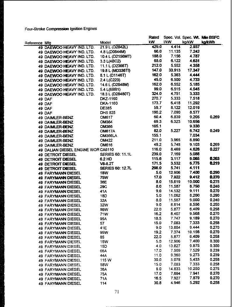
Four-Stroke Compression Ignition Engines
Rated Spec. Vol. Spec. WL Mb» BSFC Reference Mfq Model kW l/kW kg/kW kOfcWh
49 DAEWOO HEAVY IND. LTD. 21.9L(D2842L) 429.0 4.414 2.937 49 DAEWOO HEAVY IND. LTD. 4.8 L(D0844M) 66.0 11.135 7.242 49 DAEWOO HEAVY IND. LTD. 10.4L(D2156MT) 188.0 7.156 4.787 49 DAEWOO HEAVY IND. LTD. 3.3 L(4BC2) 65.0 6.122 4.631 49 DAEWOO HEAVY IND. LTD. 11.1 L(D2366T) 212.0 5.552 4.358 49 DAEWOO HEAVY IND. LTD. 19.8L(MD336TI) 147.0 33.913 17.347 49 DAEWOO HEAVY IND. LTD. 8.1L(D1146T) 162.0 5.363 4.444 49 DAEWOO HEAVY IND. LTD. 2.4 L(C223) 45.0 6.500 4.733 49 DAEWOO HEAVY IND. LTD. 14.6L(D2848M) 162.0 6.552 5.185 49 DAEWOO HEAVY IND. LTD. 5.4 L(6BB1) 99.0 6.515 4.545 49 DAEWOO HEAVY IND. LTD. 18.3L(D28480T) 324.0 4.751 3.333 49 DAF DKZ-1160 270.7 5.333 7.518 49 DAF DKA-1160 173.7 6.418 11.292 49 DAF DE385 59.7 8.122 12.019 49 DAF DHS 825 190.2 7.090 8.577 49 DAIMLER-BENZ OM617 60.4 6.839 9.205 0.269 49 DAIMLER-BENZ OM364 69.3 6.323 10.653 49 DAIMLER-BENZ OM366 105.1 9.330 49 DAIMLER-BENZ OM617A 82.0 5.227 6.742 0.249 49 DAIMLER-BENZ OM366LA 155.1 7.034 49 DAIMLER-BENZ OM422 211.0 3.965 8.890 49 DAIMLER-BENZ OM616 49.2 5.748 9.103 0.269 49 DALIAN DIESEL ENGINE WOR CA6110 116.0 8.469 4.828 0.227 49 DETROIT DIESEL SERIES 60:11.1L 239.0 7.169 5.088 49 DETROIT DIESEL 6.2 HD 115.6 3.117 6.065 ©263 49 DETROIT DIESEL V8-8.2T 171.5 3.532 6.775 0219 49 DETROIT DIESEL SERIES 60:12.7L 298.0 5.741 4.111 49 FARYMANN DIESEL 18W 5.0 12.906 7.400 0.290 49 FARYMANN DIESEL 75W 17.0 7.922 9.412 0270 49 FARYMANN DIESEL 36E 8.0 15.619 10.000 0275 49 FARYMANN DIESEL 29C 8.0 11.587 8.750 0240 49 FARYMANN DIESEL 41A 9.0 14.532 9.111 0270 49 FARYMANN DIESEL 18D 5.0 11.062 8.200 0290 49 FARYMANN DIESEL 32A 8.0 11.587 9.000 0.240 49 FARYMANN DIESEL 32W 9.0 8.814 8.556 0.250 49 FARYMANN DIESEL 86W 22.0 5.877 6.409 0258 49 FARYMANN DIESEL 71W 16.2 8.407 9.568 0270 49 FARYMANN DIESEL 95A 18.5 7.747 9.189 0270 49 FARYMANN DIESEL 57 15.0 7.083 7.333 0258 49 FARYMANN DIESEL 41E 9.0 13.884 9.444 0270 49 FARYMANN DIESEL 95W 19.2 7.374 10.156 0270 49 FARYMANN DIESEL 85 22.0 5.877 6.409 0258 49 FARYMANN DIESEL 15W 5.0 12.906 7.400 0.300 49 FARYMANN DIESEL 15D 4.0 13.827 9.875 0.300 49 FARYMANN DIESEL 66A 17.0 7.509 7.529 0.239 49 FARYMANN DIESEL 44A 11.0 9.360 9.273 0.239 49 FARYMANN DIESEL 115W 30.0 5.078 5.433 0.258 49 FARYMANN DIESEL 58W 15.0 7.083 7.333 0.258 49 FARYMANN DIESEL 36A 8.0 14.833 10.250 0.275 49 FARYMANN DIESEL 75A 17.0 7.694 7.941 0.270 49 FARYMANN DIESEL 71A 16.5 7.927 7.879 0270 49 FARYMANN DIESEL 114 30.8 4.946 5.292 0258
71

Four-Strote Gompresssoim Igniion Engjress
Reference Mfq FARYMANN DIESEL
Mode!
49 49 FIAT 49 FIAT 49 GARDNER 49 GARDNER 49 HIN© MOTORS 49 HINO MOTORS 49 HINO MOTORS 49 HINO MOTORS 49 HINO MOTORS 49 HINO »TORS 49 HINO MOTORS 49 HINO MOTORS 49 HINO MOTORS 49 HINO MOTORS 49 HINO MOTORS 49 HINO MOTORS 49 HINO MOTORS 49 HINO MOTORS 49 HINO MOTORS 49 HINO MOTORS 49 HINO MOTORS 49 HINO MOTORS 49 HINO MOTORS 49 HINO MOTORS 49 HINO MOTORS 49 HINO MOTORS 49 HINO MOTORS 49 HINO MOTORS 49 HINO MOTORS 49 HINO MOTORS 49 HINO MOTORS 49 HINO MOTORS 49 HINO MOTORS 49 HINO MOTORS 49 HINO MOTORS 49 HiNO MOTORS 49 ISUZU MOTORS LIMITED 49 ISUZU MOTORS LIMITED 49 ISUZU MOTORS LIMITED 49 ISUZU MOTORS LIMITED 49 ISUZU MOTORS LIMITED 49 ISUZU MOTORS LIMITED 49 ISUZU MOTORS LIMITED 49 ISUZU MOTORS LIMITED 49 ISUZU MOTORS LIMITED 49 ISUZU MOTORS LIMITED 49 ISUZU MOTORS LIMITED 49 ISUZU MOTORS LIMITED 49 ISUZU MOTORS LIMITED 49 ISUZU MOTORS LIMITED 49 ISUZU MOTORS LIMITED
21A 8340.04 8140.61 6LXCT 6LXDT EM100 EK130-T EP100-T W04G-T W04D EF750T H08C-T P11C EK100 WQ6D EP100-T! EH700 W04C-T EM10U EH700 P09C H06C-TI H05C-T EF750 W04C H07C WQ6D EM100 EF750T EK200 EK1O0 EF750 W04D EP100-TI H06C-T EF750T W06E 6BG1T UM6BD1MTC3 QD-40 4HF1 6BG1TC 6BD1 6BD1T 2KC1 QD-60 6WA1TC 6SA1T 4BD1T 6BD1T 6RB1 4JB1
Rated Spec. Vol. Spec. WL Mb» BSFC kW l/kW kq/kW I <0®m
6.0 8.908 8I833'" 0.26® 75.3 6.862 12.003 0.214 56.7 3.988 8.487 0.24®
169.3 11.177 205.2 6.160 9.220 114.0 8.621 6.481 173.0 9.581 6.068 127.0 8.913 6.063 103.0 3.648 3.301 84.5 4.327 3.716
272.0 6.720 4.441 151.0 5.060 3.616 239.0 7.626 3.791 198.0 7.669 4.948 110.5 4.430 3.837 212.5 5.327 7.988
91.0 8.127 5.485 84.0 5.171 4.226
174.0 8.505 4.828 121.0 5.903 4.298 232.0 7.220 3.953 138.0 5.873 4.203 113.0 6.669 4.823 243.0 7.474 4.815
77.5 4.848 4.0S2 132.0 11.504 7.424 87.0 6.374 4.828
163.0 5.962 4.540 243.8 10.277 11.278 0L2I4 198.0 6.428 5.202 153.0 9.193 6.405 186.0 11.876 6.280 62.0 6.966 5.484
214.0 5.940 4.028 129.8 5.805 9.249 0.216 214.0 11.690 5.607 121.0 4.046 3.471 127.5 5.69S 3.960 157.3 5.343 4.029 30.6 8.855 15.635 0.271 99.0 3.384
147.0 6.624 3.878 113.3 6.234 4.102 123.0 5.948 8.599
11.3 12.368 8.437 41.8 7.087 11.758 0.268
280.0 3.857 145.4 5.973 4.264
76.1 6.390 4.299 115.6 5.253 4.283 168.5 7.179 5.696 43.3 8.152 5.803
72

Four-Stroke Compression Ignition Engines
Rated Spec. Vol. Spec. Wt. MBIBSFC
Reference Mfq Model kW l/kW kq/kW ko/MMi 49 ISUZU MOTORS LIMITED 6RB1T 196.9 7.571 5.435 49 ISUZU MOTORS LIMITED 4BD1 61.9 7.106 5.203 49 ISUZU MOTORS LIMITED 3KC1 17.5 9.399 5.878 49 ISUZU MOTORS LIMITED 3KR1 22.0 9.595 6.001 49 ISUZU MOTORS LIMITED 6BD1 96.9 6.740 4.694 49 ISUZU MOTORS LIMITED QD-90 58.2 7.938 11.932 0225 49 ISUZU MOTORS LIMITED C240 43.3 8.130 6.243 49 ISUZU MOTORS LIMITED C240 33.6 8.852 6.646 49 ISUZU MOTORS LIMITED 3AB1 25.4 10.745 8.559 49 ISUZU MOTORS LIMITED 6RA1T 210.0 9.293 4.929 0213 49 ISUZU MOTORS LIMITED 6SA1T 164.1 4.917 3.444 0228 49 ISUZU MOTORS LIMITED 6HE1-N 121.0 4.207 0230 49 ISUZU MOTORS LIMITED 6HE1-S 143.0 3.559 0230 49 ISUZU MOTORS LIMITED 6SA1 117.1 7.136 5.040 49 ISUZU MOTORS LIMITED 6BB1 83.5 7.824 5.448 49 ISUZU MOTORS LTD. 1.817 L4FB1 38.0 7.127 4.579 49 JOHN DEERE 6068D 97.0 6.062 49 JOHN DEERE 60S9D 89.0 5.820 49 JOHN DEERE 3179D 43.0 6.698 7.512 49 JOHN DEERE 6076H 183.0 4.339 49 JOHN DEERE 4039D 60.0 7.033 49 JOHN DEERE 6059T 123.0 4.268 49 JOHN DEERE 4045T 86.0 5.663 49 JOHN DEERE 4239A 87.0 5.253 49 JOHN DEERE 4039T 82.0 5.329 49 JOHN DEERE 6619A 225.0 4.929 49 JOHN DEERE 6076A 168.0 4.948 49 JOHN DEERE 3179T 59.0 5.593 49 JOHN DEERE 4045D 63.0 7.524 49 JOHN DEERE 6359A 131.0 4.350 4.733 49 JOHN DEERE 6068T 130.0 4.631 49 JOHN DEERE 6466A 168.5 4.928 10.681 0216 49 KOMATSU SA6D110-1 164.1 5.758 8.065 0206 49 KOMATSU 6D125-1 152.9 6.446 12.187 0211 49 KOMATSU SA6D140 368.0 3.885 3.342 49 KOMATSU SA12V170 1102.9 4.248 8.755 49 KOMATSU S6D140 294.0 4.863 4.082 49 KOMATSU SA8V140 459.3 3.656 7.384 49 KOMATSU SA6D125-1 275.9 3.884 7.191 0.196 49 KUBOTA D1105-B 18.6 6.222 49 KUBOTA D1005-B 19.4 5.983 49 KUBOTA V1205-B 23.5 5.662 49 KUBOTA D3200B 49.2 6.683 14.122 0.228 49 KUBOTA V1505-B 24.6 5.405 49 KUBOTA WG750-B 17.2 3.597 49 KUBOTA D905-B 17.5 6.620 49 KUBOTA V4300B 65.6 6.124 12.816 0.225 49 KUBOTA V1902B 31.3 7.422 13.666 0.262 49 KUBOTA V1305-B 25.7 5.170 49 KUBOTA WG600-B 14.2 4.355 49 M.A.N. D2556MK 237.9 7.595 7.878 49 M.A.N. D0226MKF 146.2 5.041 6.486
73

Four-Stroke Com^esaomi Ignition Engines
Rated Spec. Vol. Spec. Wt Mm BSFC
Reference Mfg Model kW l/kW kp/kW ko/kWfo 49 MACK E6-350-4VHCMCAC 261.0 7.989 0.208 49 MITSUBISHI MOTORS CORP. , 4D31T 89.5 4.555 7.264 49 MITSUBISHI MOTORS CORP. , 6D14 115.6 5.065 9.820 49 MITSUBISHI MOTORS CORP. , 6D16 136.1 5.323 3.584 49 MITSUBISHI MOTORS CORP. . 6D22T3 246.1 7.593 8.550 49 MSTSUBISHB MOTORS CORP. 6D22 167.8 12.176 11.7» 49 MSTSUBISHB MOTORS CORP. 6D14T 145.4 4.928 8.259 49 msm D22S-4 62.6 5.462 12.500 49 MMS D226.6T 114.1 5.063 9.221 49 NAVISTAR T444E:HEUI 160.3 3.121
49 NAVISTAR DT-239 67.1 6.521 13.783 0.253 49 NAVISTAR 6.9 L 126.8 5.180 6.705 49 NISSAN DIESEL SD1604 25.0 7.197 49 NISSAN DIESEL PE6 151.4 3.691 12.081 49 NISSAN DIESEL SD33 65.6 7.269 10.073 49 NISSAN DIESEL PE6-TA 216.3 10.173
49 NISSAN DIESEL SD226J 34.6 8.67S 49 NISSAN DIESEL TD2704 51.5 4.855 49 NISSAN DIESEL BD3O04 55.2 4.714 49 NISSAN DIESEL TD2304 44.1 5.665 49 NISSAN DIESEL ND6 97.7 9.528 12.868 49 NISSAN DIESEL FD3504 62.5 4.878 49 NISSAN DIESEL NE6 130.5 4.904 49 NISSAN DIESEL SD3304 53.0 5.685 49 NISSAN DIESEL SD33SJ 53.7 7.171
■ 49 NSSSAN DIESEL SD22 44.7 5.612 10.594 49 NISSAN DIESEL FD3304 58.8 5.150 49 NISSAN DIESEL FD35TA1® 95.6 6.223 49 NISSAM DIESEL FDS14 84.6 5.403 49 NISSAN DIESEL SD2204 34.6 6.219 49 NISSAN DIESEL FD35T04 77.2 4.208
49 NISSAN DIESEL FD33T04 73.6 4.351 49 NISSAN DIESEL SD33T6 61.8 8.498 49 NISSAN DIESEL SD2504 39.7 5.539
49 NISSAN DIESEL ND6T 120.8 15.433 11.225
49 NISSAN DIESEL FD60S 84.6 8.631 49 NISSAN DIESEL NE6T 156.6 4.246
49 NISSAN DIESEL FE6 126.8 4.023 49 NISSAN DIESEL SD33T 78.3 5.281 8.289
49 PERKINS 4.2032 44.0 7.980 11.728 0.255
49 PERKINS 4.108 32.8 6.154 15.544 0.257
49 PERKINS T6.60 CC 134.2 4.498 8.568
49 PERKINS TV8.640 187.2 4.564 10.258
49 PERKINS T4.40 CC 89.5 5.454 8.694
49 PEUGEOT SA 2.3 L XD2S 60.7 3.542
49 PEUGEOT SA 2.3 L XD2 51.5 3.883
49 POYAUD 060212 131.2 3.553 8.648
49 POYAUD 062030S 175.2 6.072 10.985
49 RENAULT 062045 MIDR 220.0 4.965 8.819
49 RENAULT 063540 231.2 6.301 10.962
49 RENAULT 720 65.6 5.047 10.408
49 SCANIA DSC11.03 254.3 8.585 0.204
74

Four-Stroke Compression Ignition Engines
Reference Mfg 49 49 49 49 49 49 49 49 49 49 49 49 49 49 49 49 49 49 49 49 49 49 49 49 49 49 49 49 49 49 49 49 49 49 49 49 49 49 49 49 49 49 49 49 49 49 49 49 49 49 49 49
SCANIA SCANIA SSANGYONG SSANGYONG SSANGYONG SSANGYONG SSANGYONG SSANGYONG SSANGYONG SSANGYONG SSANGYONG SSANGYONG SSANGYONG SSANGYONG SSANGYONG SSANGYONG SSANGYONG SSANGYONG SSANGYONG SSANGYONG SSANGYONG SSANGYONG SSANGYONG SSANGYONG SSANGYONG SSANGYONG SSANGYONG SSANGYONG SSANGYONG SSANGYONG SSANGYONG SSANGYONG SSANGYONG SSANGYONG SSANGYONG SSANGYONG SSANGYONG SSANGYONG SSANGYONG SSANGYONG SSANGYONG SSANGYONG SSANGYONG SSANGYONG SSANGYONG SSANGYONG SSANGYONG SSANGYONG SSANGYONG SSANGYONG STEYR STEYR
HEAVY IND. HEAVY IND HEAVY IND HEAVY IND. HEAVY IND HEAVY IND HEAVY IND HEAVY IND HEAVY IND HEAVY IND HEAVY IND HEAVY IND HEAVY IND HEAVY IND HEAVY IND HEAVY IND HEAVY IND HEAVY IND HEAVY IND HEAVY IND HEAVY IND HEAVY IND. HEAVY IND HEAVY IND HEAVY IND. HEAVY IND HEAVY IND HEAVY IND HEAVY IND HEAVY IND HEAVY IND HEAVY IND HEAVY IND HEAVY IND HEAVY IND HEAVY IND HEAVY IND HEAVY IND HEAVY IND HEAVY IND HEAVY IND HEAVY IND HEAVY IND HEAVY IND HEAVY IND HEAVY IND HEAVY IND HEAVY IND
Rated ! Spec. Vol. Spec. Wt Affin BSFC Model kW /kW I «3/kW ko/kWh DSC9 211.8 5.198 8.330 DS14.01 324.4 5.456 8.086 0209 WARTSILA 12V32 4920.0 15.618 15.152 MANB&W9L28/32H 1980.0 21.668 12.741 WARTSILA 12V22 2100.0 9.405 13.074 WARTSILA 8V22 1400.0 8.691 12.662 WARTSILA 18V32 7380.0 11.890 6.898 WARTSILA 16V32 6560.0 14.345 12.611 WARTSILA 6R22/26 1125.0 12.819 7.515 WARTSILA 16V32 6560.0 11.315 7.206 WARTSILA 6R22/26 1065.0 12.475 14.938 MANB&W6L28/32H 1320.0 19.494 14.291 WARTSILA 16V22 2800.0 10.434 6.591 MAN B&W 8L28/32H 1760.0 21.968 12.887 WARTSILA 4R22/26 710.0 15.274 19.462 WARTSILA 4R32 1640.0 16.340 18.847 WARTSILA 9R32 3690.0 16.479 17.248 WARTSILA 8R22/26 1500.0 11.384 6.848 MANB&W5L23/30 800.0 20.591 13.807 MANB&WT23LH-4E 550.0 14.274 16.033 WARTSILA 8R22 1400.0 12.197 7.338 WARTSILA 8R32 3280.0 17.068 17.461 MAN B&W 7L28/32H 1540.0 22.099 13.312 WARTSILA 8R22 1400.0 14.970 13.508 WARTSILA 8V22 1400.0 12.838 6.558 WARTSILA 4R22 700.0 16.811 9.870 WARTSILA 16V22 2800.0 8.948 12.249 WARTSILA 8R32 3280.0 15.361 9.83S WARTSILA 9R32 3690.0 16.386 9.851 MAN B&W 8L23/30 1280.0 20.516 11.222 WARTSILA 6R32 2460.0 17.454 9.608 WARTSILA 4R22 700.0 17.403 19.740 WARTSILA 12V22 2100.0 11.864 6.667 MAN B&W 7L23/30 1120.0 17.929 11.607 MAN B&W 6L23/30 960.0 19.038 12.216 WARTSILA 6R22 1050.0 13.735 8.052 WARTSILA 4R32 1640.0 20.008 10.255 WARTSILA 4R22/26 750.0 15.690 9.212 WARTSILA 18V32 7380.0 14.223 12.318 SULZER 9S20 1440.0 17.022 8.144 WARTSILA 6R32 2460.0 14.485 16.630 SULZER 8S20 1280.0 17.763 8.381 MANB&W18V28/32H 3960.0 15.790 10.813 SULZER 6S20 960.0 18.384 8.902 WARTSILA 6R22 1050.0 14.304 15.152 WARTSILA 8R22/26 1420.0 13.000 13.316 MAN B&W 12V28/32H 3585.0 9.679 8.381 MAN B&W 5L28/32H 1100.0 21.004 15.000 MANB&W16V28/32H 4785.0 11.081 8.673 WARTSILA 12V32 4920.0 13.802 7.945 610 99.2 6.358 11.999 0231 615.68 230.4 3.575 7.725
75
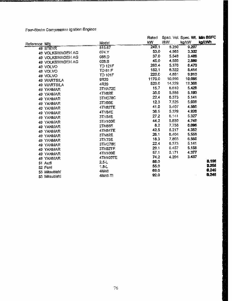
Foor-Strote Conrapressioira Ignition Engines
Rated Spec. Vol. Spec. WL Mn BSFC
Reference Mfts Mode! kW l/kW ko/kW tefMMn
49 STEYR 815.67 249.1 5.250 9207
49 VOLKSWAGEN AG Q74.Y 53.0 4.565 3.302
49 VOLKSWAGEN AG 088.D 37.0 5.548 3.486
49 VOLKSWAGEN AG 028.B 45.0 4.586 2J8B
49 VOLVO TD121F 283.4 5.378 8.470
49 VOLVO TD61F 152.1 6.322 8.414
49 VOLVO TD101F 220.0 4.881 9.910
49 WARTSBLA 9R20 1170.0 10.999 10.08S
49 WARTSSLA 4R20 520.0 14.229 12.308
49 YANMAR 3TNA72E 15.7 6.810 5.42S
49 YANMAR 4TN82E 35.0 5.555 5.193
49 YANMAR 3TNC78C 22.4 6.373 5.141
49 YANMAR 3TN6SE 12.3 7.525 5.03S
49 YANMAR 4TN82TE 41.0 5.407 4.56«
49 YANMAR 4TN84E 36.5 5.329 4.926
49 YANMAR 3TN84E 27.2 6.141 5.327
49 YANMAR 3TN1O0E 44.2 5.659 4.74S
49 YANMAR 2TN86E 8.2 7.758 6.09S
49 YANMAR 4TNS4TE 42.5 5.217 4.352
49 YANMAR 3TN82E 26.1 6.404 5.556
49 YANMAR 3TN75E 18.3 7.803 6.568
49 YANMAR 3TNC78E 22.4 6.373 5.141
49 YANMAR 3TN82TE 29.1 6.457 5.158
49 YANMAR 4TN1OTE 57.1 5.171 4.377
49 YANMAR 4TN100TE 74.2 4.294 3.43?
51 Aarfi 2.5-L 88.0 ■LIM 52 Foinä 1.8-L 55.0 tSUÜ
53 MisobisSiJ "ff6ul&!Hy< 89.0 §.241
53 MHsuk&tfi 4M40-T! 02.0 ÜL241
76
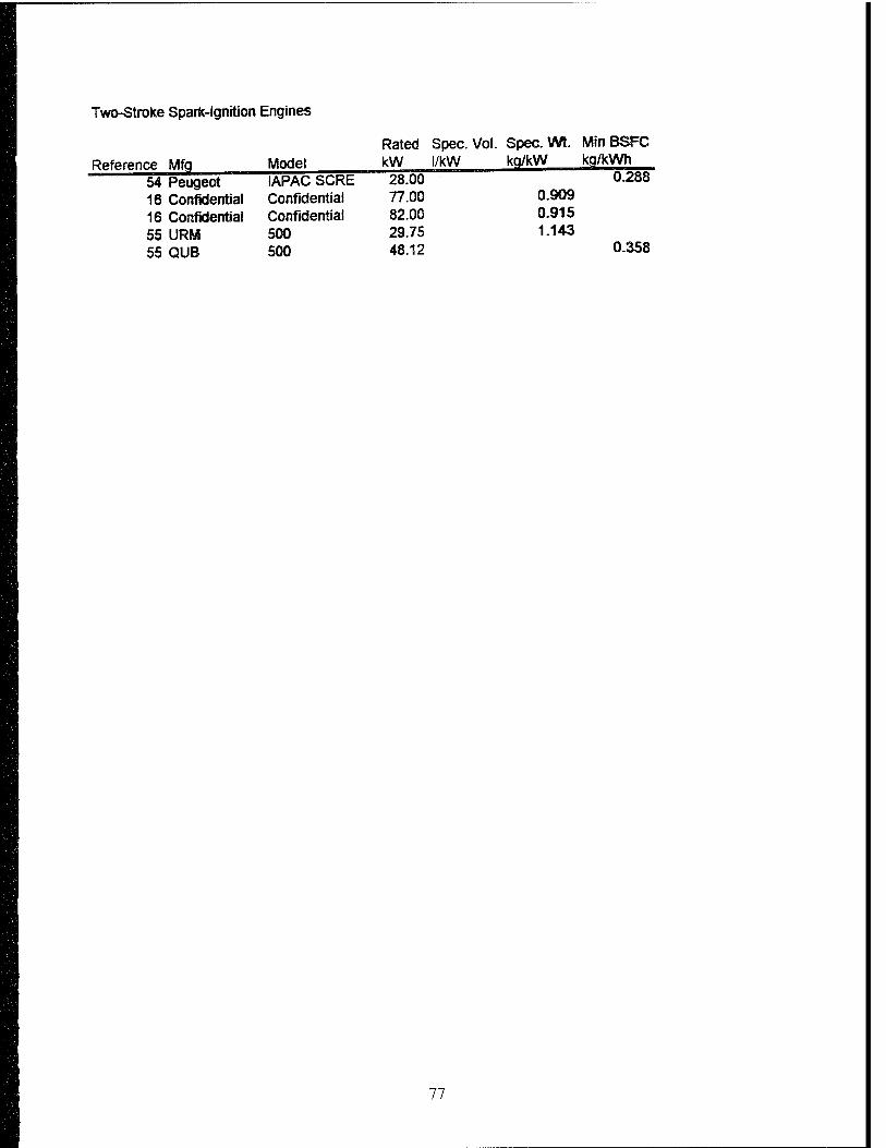
Two-Stroke Spark-Ignition Engines
Rated Spec. Vol. Spec. Wt. MinBSFC
Reference Mfq Model kW l/kW ka/kW kg/kWh
54 Peugeot IAPAC SCRE 28.00 0.288
16 Confidential Confidential 77.00 0.909
16 Confidential Confidential 82.00 0.915
55 URM 500 29.75 1.143
55 QUB 500 48.12 0.358
77
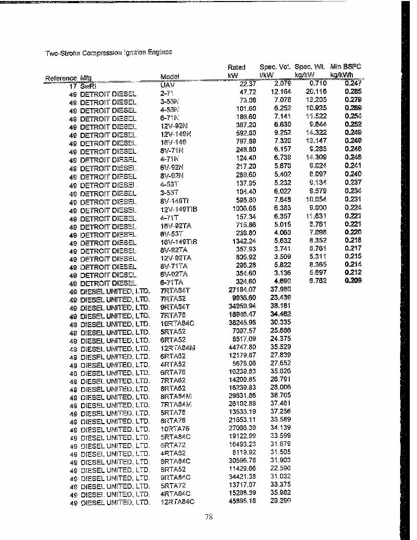
Two-Stroke Compression Ignition Engines
Rated : Spec. Vol. : Spec. Wl. Min BSFC
Reference Mfp Model kW 22.37
l/kW 2.07®
kp/kW 0.710
kq/kWfe 0247 17 SwRI UAV
4® DETROIT DIESEL 2-71 47.72 12.164 20.116 0285
49 DETROIT DIESEL 3-53N 73.08 7.Q78 13.205 027®
4® DETROIT DIESEL 4-53N 101.60 6.252 10.925 Q26S-
4® DETROIT DIESEL 6-71N 186.60 7.141 11.522 0.254
4® DETROIT DIESEL 12W-92N 397.20 6.630 9.S44 0252.
4® DETROIT DIESEL 12V-149N 592.80 9.252 14.322 0248
4® DETROIT DIESEL 16V-149 797.89 7.320 13.147 024S-
4® DETROIT DIESEL 8V-71N 248.80 6.157 9.285 024®
4® DETROIT DIESEL 4-71N 124.40 6.739 14.309 0246
49 DETROIT DIESEL 6V-92N 217.20 5.670 9.024 0241
4® DETROIT DIESEL 8V-92N 289.60 5.402 8.097 0240
4® DETROIT DIESEL 4-53T 137.95 5.232 9.134 0237
4® DETROIT DIESEL 3-53T 104.40 6.022 9.579 0234
4® DETROIT DIESEL 8V-149TI 5SS.80 7.648 10.054 0231
4® DETROIT DIESEL 12V-149TIB 1006.68 6.383 9.000 0.224
4® DETROIT DIESEL 4-71T 157.34 6.357 11.631 0221
4® DETROIT DIESEL 16V-92TA 715.86 5.015 6.761 0221
4® DETROIT DIESEL 6¥-53T 238.80 4.060 7.098 0220
4® DETROIT DIESEL 16V-149TIB 1342.24 5.632 8.352 0218
4® DETROIT DIESEL 8V-92TÄ 357.93 3.741 6.761 0217
49 DETROIT DIESEL 12V-92TA 805.92 3.509 5.311 0215
4® DETROIT DIESEL 8W-71TA 298.28 5.822 8.365 0214
4® DETROIT DIESEL 6V-92TA 354.60 3.136 5.697 0212
4® DETROIT DIESEL &-71TA 324.60 4.690 @.762 02G8
4® DIESEL UNITED, LTD. 7RTA84T 27184.07 37.98®
4® DIESEL UNITED, LTD. 7KTA52 9936.50 23.43®
4§ DIESEL UNITED, LTD. 9RTAS4T 34950.94 38.181
4® DFSHL UNITED, LTD. 7HTA7® WBm.47 34.462
4® DIESEL UNITED, LTD. 10RTA84C 38245.98 30.335
4® DIESEL UNITED, LTD. 5RTA52 7097.57 25.686
4® DIESEL UNITED, LTD. 6RTA52 8517.09 24.375
49 DIESEL UNITED, LTD. 12RTA84M 44747.80 35.529
4® DIESEL UNITED, LTD. 6RTA62 12179.87 27.839
49 DIESEL UNITED, LTD. 4RTA52 5678.06 27.652
4® DIESEL UNITED, LTD. SRTA76 16239.83 35.626
4® DIESEL UNITED, LTD. 7RTA62 14209.85 26.791
4® DIESEL UNITED, LTD. 8RTA62 16239.83 26.006
49 DIESEL UNITED, LTD. 8RTA84M 29831.86 38.705
49 DIESEL UNITED, LTD. 7RTA84M 26102.88 37.461
49 DIESEL UNITED, LTD. 5RTA76 13533.19 37.256
4® DIESEL UNITED, LTD. 8RTA76 21653.11 33.589
49 DIESEL UNITED, LTD. 10RTA76 27066.39 34.139
49 DIESEL UNITED, LTD. 5RTA84C 19122.99 33.599
49 DIESEL UNITED, LTD. 6RTA72 16493.23 31.679
49 DIESEL UNITED, LTD. 4RTA62 8119.92 31.505
49 DIESEL UNITED, LTD. 8RTA84C 30596.78 31.903
49 DIESEL UNITED, LTD. 8RTA52 11429.66 22.590
49 DIESEL UNITED, LTD. 9RTA84C 34421.38 31.032
49 DIESEL UNITED, LTD. 5RTA72 13717.07 33.375
49 DIESEL UNITED, LTD. 4RTA84C 15298.39 35.982
4® DIESEL UNITED, LTD. 12RTA84C 45895.18 29.290
78
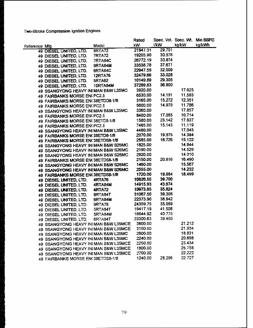
Two-Stroke Compression ignition Engines
Reference Mfg 49 DIESEL UNITED, LTD. 49 DIESEL UNITED, LTD. 49 DIESEL UNITED, LTD. 49 DIESEL UNITED, LTD. 49 DIESEL UNITED, LTD. 49 DIESEL UNITED, LTD. 49 DIESEL UNITED, LTD. 49 DIESEL UNITED, LTD. 49 SSANGYONG HEAVY INI 49 FAIRBANKS MORSE EN( 49 FAIRBANKS MORSE EN( 49 FAIRBANKS MORSE ENC 49 SSANGYONG HEAVY INI 49 FAIRBANKS MORSE EN( 49 FAIRBANKS MORSE ENC 49 FAIRBANKS MORSE EN( 49 SSANGYONG HEAVY INI 49 FAIRBANKS MORSE EN( 49 FAIRBANKS MORSE ENC 49 SSANGYONG HEAVY INI 49 SSANGYONG HEAVY INI 49 SSANGYONG HEAVY INI 49 FAIRBANKS MORSE ENC 49 SSANGYONG HEAVY INI 49 SSANGYONG HEAVY INI 49 FAIRBANKS MORSE ENC 49 DIESEL UNITED. LTD. 49 DIESEL UNITED, LTD. 49 DIESELUNfTED, LTD. 49 DIESEL UNITED, LTD. 49 DIESEL UNITED, LTD. 49 DIESEL UNITED, LTD. 49 DIESEL UNITED, LTD. 49 DIESEL UNITED, LTD. 49 DIESEL UNITED, LTD. 49 SSANGYONG HEAVY INI 49 SSANGYONG HEAVY INI 49 SSANGYONG HEAVY INI 49 SSANGYONG HEAVY INI 49 SSANGYONG HEAVY INI 49 SSANGYONG HEAVY INI 49 SSANGYONG HEAVY INI 49 FAIRBANKS MORSE ENC
Rated Spec. Vol. Spec. Wt. MinBSFC Model kW /kW kg/kW kg/kWh 8RTA72 21947.31 29.701 7RTA72 19203.90 30.576 7RTA84C 26772.19 30.874 9RTA84M 33538.78 37.671 6RTA84C 22947.59 32.009 12RTA76 32479.66 33.028 5RTA62 10149.89 29.305 10RTA84M 37289.83 36.800 MANB&WL35MC 3920.00 17.625 PC2.5 6530.00 14.191 11.593 38ETDD8-1/8 3165.00 15.272 12.351 PC2.5 5600.00 14.979 11.786 MAN B&W L35MC 3360.00 17.857 PC2.5 8400.00 17.085 10.714 38ETD8-1/8 1580.00 23.142 17.837 PC2.5 7465.00 15.143 11.119 MANB&WL35MC 4480.00 17.045 38ETD8-1/8 2370.00 19.975 14.384 38ETDS8-1/8 2585.00 18.726 15.122 MAN B&W S26MC 1825.00 14.944 MAN B&W S26MC 2190.00 14.529 MAN B&W S26MC 2920.00 14.010 38ETDS8-1/8 2150.00 20.816 16.490 MANB&WS26MC 1460.00 15.567 MANB&WS2SMG 2555.00 14.232 38ETDS8-1/8 1720.00 19.984 18.499 4RTA76 10826.55 39.700 4RTA84M 14915.93 43.674 4RTA72 10973.65 35.824 8RTA84T 31067.50 39.308 6RTA84M 22373.90 38.842 9RTA76 24359.75 35.089 5RTA84T 19417.19 41.508 5RTA84M 18644.92 40.775 6RTA84T 23300.63 39.450 MAN B&W L35MCE 3600.00 21.212 MAN B&W L35MCE 3150.00 21.934 MAN B&W L35MC 2800.00 18.831 MAN B&W L35MC 2240.00 20.698 MAN B&W L35MCE 2250.00 23.434 MAN B&W L35MCE 1800.00 25.758 MAN B&W L35MCE 2700.00 22.222 38ETDS8-1/8 1240.00 28.296 22.727
79

Rotary Engines
Reference Mfg Model 1 Pmsdicted best attainabfe
24 AMs AR731 2 Norton 2 Rotac
56 YaBimar R220 56 Yanmar R450 57 Nestom, AAI Modifications NR631 58 JTOI DemfWa» 2116 R 58 JTDI 580 Series 58 JTDI 580 Series 58 JTDI 580 Series
Rated Spec. Vol. Spec. Wl Min BSFC kW i/kW kg/kW kg/kWh
30.00 1.000 1.300 O.30S 28.30 0.360 0.350 0.316 30.00 1.400 0.700 0.300 25.00 1.200 1.100 0.360 16.55 0.382 36.78 0.382. 28.50 1.195 0.320
560.00 0.23© 846.37 0.224 149.14 0.268 300.00 0.760 0.237
80
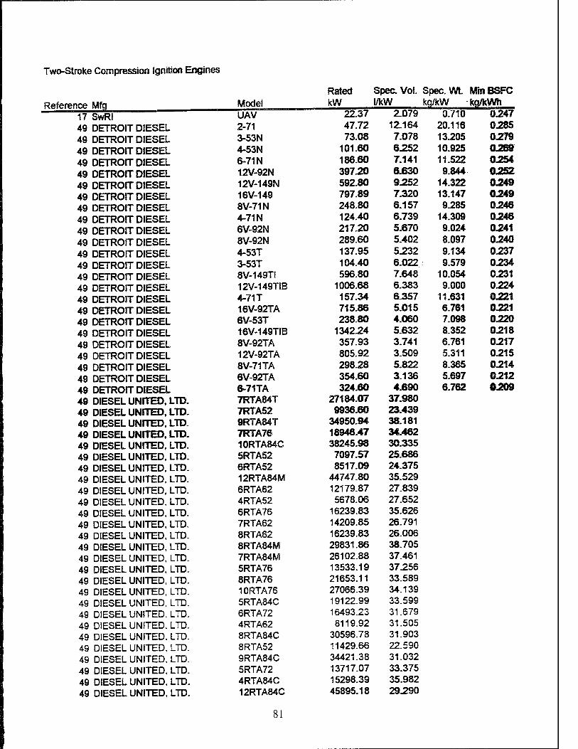
Two-Stroke Compression Ignition Engines
Reference 17 49 49 49 49 49 49 49 49 49 49 49 49 49 49 49 49 49 49 49 49 49 49 49 49 49 49 49 49 49 49 49 49 49 49 49 49 49 49 49 49 49 49 49 49 49 49 49 49 49 49 49
Rated Spec Vol. Spec. WL MhlBSFC
Mfq Model kW WcW <g/kW kg/kWn
SwRI UAV 22.37 2.079 0.710 0.247
DETROIT DIESEL 2-71 47.72 12.164 20.116 0285
DETROIT DIESEL 3-53N 73.08 7.078 13.205 0279
DETROIT DIESEL 4-53N 101.60 6.252 10.925 0269
DETROIT DIESEL 6-71N 186.60 7.141 11.522 0254
DETROIT DIESEL 12V-92N 397.20 6.630 9.844 02SZ
DETROIT DIESEL 12V-149N 592.80 9.252 14.322 0249
DETROIT DIESEL 16V-149 797.89 7.320 13.147 0249
DETROIT DIESEL 8V-71N 248.80 6.157 9.285 0248
DETROIT DIESEL 4-71N 124.40 6.739 14.309 0246
DETROIT DIESEL 6V-92N 217.20 5.670 9.024 0241
DETROIT DIESEL 8V-92N 289.60 5.402 8.097 0240
DETROIT DIESEL 4-53T 137.95 5.232 9.134 0237
DETROIT DIESEL 3-53T 104.40 6.022 9.579 0234
DETROIT DIESEL 8V-149TI 596.80 7.648 10.054 0231
DETROIT DIESEL 12V-149TIB 1006.68 6.383 9.000 0224
DETROIT DIESEL 4-71T 157.34 6.357 11.631 0221
DETROIT DIESEL 16V-92TA 715.86 5.015 6.761 0221
DETROIT DIESEL 6V-53T 238.80 4.060 7.098 0220
DETROIT DIESEL 16V-149TIB 1342.24 5.632 8.352 0218
DETROIT DIESEL 8V-92TA 357.93 3.741 6.761 0217
DETROIT DIESEL 12V-92TA 805.92 3.509 5.311 0215
DETROIT DIESEL 8V-71TA 298.28 5.822 8.365 0214
DETROIT DIESEL 6V-92TA 354.60 3.136 5.697 0212
DETROIT DIESEL 6-71TA 324.60 4J690 6.762 0209 DIESEL UNITED, LTD. 7RTA84T 27184.07 37.980 DIESEL UNITED, LTD. 7RTA52 9936.60 23.439
DIESEL UNITED, LTD. 9RTA84T 34950.94 38.181 DIESEL UNITED, LTD. 7RTA76 18948.47 34.482
DIESEL UNITED, LTD. 10RTA84C 38245.98 30.335
DIESEL UNITED, LTD. 5RTA52 7097.57 25.686
DIESEL UNITED, LTD. 6RTA52 8517.09 24.375
DIESEL UNITED, LTD. 12RTA84M 44747.80 35.529
DIESEL UNITED, LTD. 6RTA62 12179.87 27.839
DIESEL UNITED, LTD. 4RTA52 5678.06 27.652
DIESEL UNITED, LTD. 6RTA76 16239.83 35.626
DIESEL UNITED, LTD. 7RTA62 14209.85 26.791
DIESEL UNITED, LTD. 8RTA62 16239.83 26.006
DIESEL UNITED, LTD. 8RTA84M 29831.86 38.705
DIESEL UNITED, LTD. 7RTA84M 26102.88 37.461 DIESEL UNITED, LTD. 5RTA76 13533.19 37.256
DIESEL UNITED, LTD. 8RTA76 21653.11 33.589 DIESEL UNITED, LTD. 10RTA76 27066.39 34.139
DIESEL UNITED, LTD. 5RTA84C 19122.99 33.599
DIESEL UNITED. LTD. 6RTA72 16493.23 31.679
DIESEL UNITED, LTD. 4RTA62 8119.92 31.505
DIESEL UNITED, LTD. 8RTA84C 30596.78 31.903
DIESEL UNITED. LTD. 8RTA52 11429.66 22.590
DIESEL UNITED, LTD. 9RTA84C 34421.38 31.032
DIESEL UNITED, LTD. 5RTA72 13717.07 33.375
DIESEL UNITED, LTD. 4RTA84C 15298.39 35.982
DIESEL UNITED, LTD. 12RTA84C 45895.18 29.290
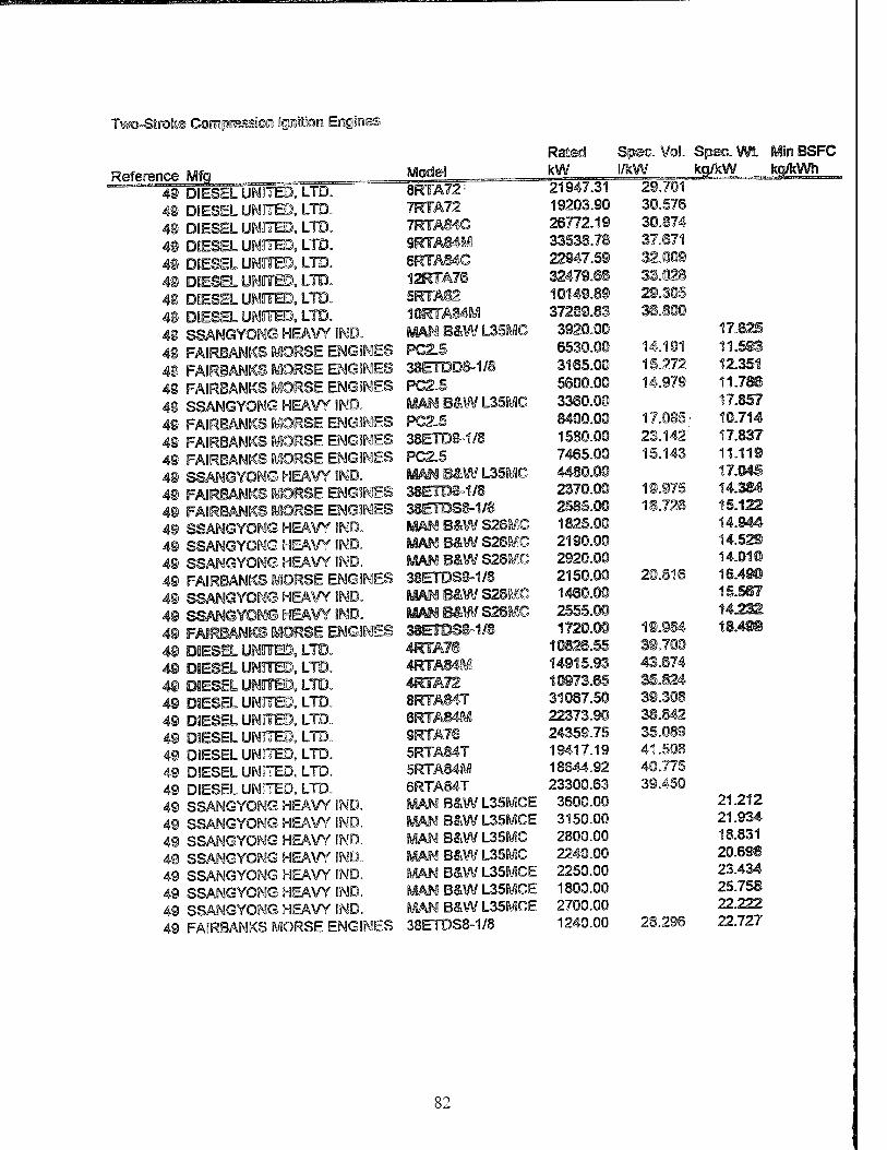
T¥OT-Strote Compressjon Ignition Engines
Rated Spec. Vol. SpecSm. MinBSFC
Reference Mfq Model kW /kW kq/kW kct/kWh
49 DIESEL UNITED, LTD. 8RTA72: 21947.31 29.701
40 DIESEL UNITED, LTD. 7RTA72 19203.90 30.576
4S DIESEL UNITED, LTD. 7RTAS4C 26772.19 30.874
49 DIESEL UNITED, LTD. 9RTAB4M 33538.78 37.871
4® DIESEL UNITED, LTD. 6RTÄ84C 22947.59 32.009
48 DIESEL UNITED, LTD. 12KTA76 32479.6S 33.028
48 DIESEL UNITED, LTD. 5RTA62 10149.89 29.305
48 DIESEL UNITED, LTD. 10RTA84M 37289.83 38.800
40 SSANGYONG HEAVY IND. MAM B&W L35MC 3920.00 17.625
49 FAIRBANKS MORSE ENGINES PC2.5 6530.00 14.191 11.598
49 FAIRBANKS MORSE ENGINES 38ETDD8-1/8 3165.00 15.272 12.351
49 FAIRBANKS MORSE ENGINES PC2.5 5600.00 14.979 11.786
49 SSANGYONG HEAVY IND. MAN B&W L35MC 3360.00 17.857
40 FAIRBANKS MORSE ENGINES PC2.5 8400.00 17.085.' 10.714
49 FAIRBANKS MORSE ENGINES 38ETDS-1/8 1580.00 23.142: 17.837
49 FAIRBANKS MORSE ENGINES PC2.5 7465.00 15.143 11.119
49 SSANGYONG HEAVY IND. Mm B&W L35MC 4480.00 17.045
49 FAIRBANKS MORSE ENGINES 38ETD8-1/8 2370.00 19.975 14.384
49 FAIRBANKS MORSE ENGINES 38ETDS8-1/8 2585.00 18.726 15.122
49 SSANGYONG HEAVY IND. MAW B&W S26MC 1825.00 14.944
49 SSANGYONG HEAVY IND. MßM B&W S26MC 2190.00 14.529
49 SSANGYONG HEAVY IND. MAN B&W S26MC 2920.00 14.010
49 FAIRBANKS MORSE ENGINES 38ETDS8-1/8 2150.00 20.816 16.490
49 SSANGYONG HEAVY IND. MAN B&W S2SMC 1460.00 15.567
49 SSANGYONG HEAVY IND. 8ÜAHB&WS2SW1C 2555.00 14J232
49 FAIRBANKS MORSE ENGINES 38erasa-i/8 1720.00 19.984 18.4«
49 DIESEL UNITED, LTD. 4RTA7® 10826.55 39.700
49 DIESEL UNITED, LTD. 4RTÄ84M 14915.93 43.674
49 DIESEL UNITED, LTD. 4RFÄ72 10973.65 35.824
49 DIESEL UNITED, LTD. 8RTÄ84T 31067.50 39.308
49 DIESEL UNITED, LTD. 6RTA84M 22373.90 38.842
49 DIESEL UNITED, LTD. 9RTA76 24359.75 35.089
49 DIESEL UNITED, LTD. 5RTA84T 19417.19 41.508
49 DIESEL UNITED, LTD. 5RTA84M 18644.92 40.775
49 DIESEL UNITED, LTD. 6RTA84T 23300.63 39.450
49 SSANGYONG HEAVY IND. MAN B&W L35MCE 3600.00 21.212
49 SSANGYONG HEAVY IND. MAN B&W L35MCE 3150.00 21.934
49 SSANGYONG HEAVY IND. MAN B&W L35MC 2800.00 18.831
49 SSANGYONG HEAVY IND. MAN B&W L35MC 2240.00 20.698
49 SSANGYONG HEAVY IND. MAN B&W L35MCE 2250.00 23.434
49 SSANGYONG HEAVY IND. MAN B&W L35MCE 1800.00 25.758
49 SSANGYONG HEAVY IND. MAN B&W L35MCE 2700.00 22.222
49 FAIRBANKS MORSE ENGINES 38ETDS8-1/8 1240.00 28.296 22.727
82
DISTRIBUTION LIST
Department of Defense
DEFENSE TECH INFO CTR CAMERON STATION ALEXANDRIA VA 22314
ODUSD ATTN: (L) MRM PETROLEUM STAFF ANALYST PENTAGON WASHINGTON DC 20301-8000
ODUSD ATTN: (ES)CI 400 ARMY NAVY DR STE 206 ARLINGTON VA 22202
DIR DLA ATTN: DLA MMSLP 8725 JOHN J KINGMAN RD STE 2533 FT BELVOIR VA 22060-6221
DIR ADV RSCH PROJ AGENCY ATTN: ARPA/ASTO 3701 N FAIRFAX DR ARLINGTON VA 22203-1714
Department of the Army
HQDA ATTN: DALOTSE 500 PENTAGON WASHINGTON DC 20310-0500
SARDA ATTN: SARD TT PENTAGON WASHINGTON DC 20310-0103
CDR AMC ATTN: AMCRD S
AMCRD E 5001 EISENHOWER AVE ALEXANDRIA VA 22333-0001
CDR ARMY TACOM ATTN: AMSTA IM LMM
AM STA IM LMB AMSTA IM LMT AMSTA TR NAC AMSTA TR R AMSTA TR D AMSTA TR M AMSTA TR M (C RAFFA) AMSTA TR M (D HERRERA) AMSTA TR M (R MUNT) AMCPM ATP USMC LNO AMCPM LAV AMCPMM113/M60 AMCPM CCE/SMHE
WARREN MI 48397-5000
MOBILITY TECH CTR BELVOIR ATTN: AMSTA RBF (M E LEPERA)
AMSTA RBXA (R E TOBEY) 10115 GRIDLEY RD STE 128 FT BELVOIR VA 22060-5843
PROG EXEC OFFICER ARMORED SYS MODERNIZATION ATTN: SFAE ASM H CDR TACOM WARREN MI 48397-5000
PROG EXEC OFFICER TACTICAL WHEELED VEHICLES ATTN: SFAE TWV TVSP
SFAE TWV FMTV SFAE TWV PLS
CDR TACOM WARREN MI 48397-5000
PROG MGR UNMANNED GROUND VEH ATTN: AMCPM UG REDSTONE ARSENAL AL 35898-8060
DIR ARMY RSCH LAB ATTN: AMSRL PB P 2800 POWDER MILL RD ADELPHIAMD 20783-1145
VEHICLE PROPULSION DIR ATTN: AMSRL VP (MS 77 12) NASA LEWIS RSCH CTR 21000 BROOKPARK RD CLEVELAND OH 44135
10
TFLRFNo. 311 Page 1 of 3

CDR ARO ATTN: AMXRO EN (D MANN) RSCH TRIANGLE PK NC 27709-2211
CDR TRADOC ATTN: ATCD SL 5 INGALLS RDBLDG 163 FT MONROE VA 23651-5194
CDR ARMY ATCOM ATTN: AMSAT I WM
AMSAT R EP (V EDWARD) 4300 GOODFELLOW BLVD ST LOUIS MO 63120-1798
CDR AVIA APPL TECH DIR ATTN: AMSAT R TP (H MORROW) FT EUSTIS VA 23604-5577
CDR ARMY SOLDIER SPT CMD ATTN: SATNC US (J SIEGEL)
SATNC UE NATICKMA 01760-5018
US ARMY INDUSTRIAL ENGRG ACTIVITY ATTN: AMXIBP ROCK ISLAND IL 61299-6000
CDR APC ATTN: SATPC L NEW CUMBERLAND PA 17070-5005
CDR ARMY TECOM ATTN: AMSTE TA R
AMSTE TC D APGMD 21005-5006
PROJ MGR PETROL WATER LOG ATTN: AMCPM PWL 4300 GOODFELLOW BLVD ST LOUIS MO 63120-1798
PROJ MGR MOBILE ELEC PWR ATTN: AMCPM MEP T
AMCPM MEP L 7798 CISSNA RD STE 200 SPRINGFIELD VA 22150-3199
CDR ARMY ARMOR CTR ATTN: ATSB CD ML
ATSB TSM T FTKNOX KY 40121-5000
CDR ARMY QM SCHOOL ATTN: ATSM PWD FT LEE VA 23001-5000
CDR ARMY TRANS SCHOOL ATTN: ATSP CD MS FT EUSTIS VA 23604-5000
CDR ARMY ENGR SCHOOL ATTN: ATSECD FT LEONARD WOOD MO 65473-5000
CDR ARMY ABERDEEN TEST CTR ATTN: STEAC EN
STEAC LI STEAC AE STEAC AA
APG MD 21005-5059
CDR ARMY YPG ATTN: STEYP MT TL M YUMAAZ 85365-9130
CDR ARMY CERL ATTN: CECER EN P O BOX 9005 CHAMPAIGN IL 61826-9005
Department of the Navy
OFC CHIEF NAVAL OPER ATTN: DR A ROBERTS (N420) 2000 NAVY PENTAGON WASHINGTON DC 20350-2000
CDR NAVAL SEA SYSTEMS CMD ATTN: SEA 03M3 2531 JEFFERSON DAVIS HWY ARLINGTON VA 22242-5160
CDR NAVAL SURFACE WARFARE CTR ATTN: CODE 63
CODE 632 CODE 859
3A LEGGETT CIRCLE ANNAPOLIS MD 21402-5067
TFLRFNo. 311 Page 2 of 3
Department of the Navy/U.S. Marine Corps
HQ USMC ATTN: LPP WASHINGTON DC 20380-0001
PROG MGR COMBAT SER SPT MARINE CORPS SYS CMD 2033 BARNETT AVE STE 315 QUANTICOVA 22134-5080
PROG MGR GROUND WEAPONS MARINE CORPS SYS CMD 2033 BARNETT AVE QUANTICO VA 22134-5080
PROG MGR ENGR SYS MARINE CORPS SYS CMD 2033 BARNETT AVE QUANTICO VA 22134-5080
CDR 2ND MARINE DIV PSC BOX 20090 CAMP LEJEUNNE NC 28542-0090
CDR 1ST MARINE DIV CAMP PENDLETON CA 92055-5702
Department of the Air Force
HQ USAF/LGSF ATTN: FUELS POLICY 1030 AIR FORCE PENTAGON WASHINGTON DC 20330-1030
SA ALC/LDPG ATTN: D ELLIOTT 580 PERRIN BLDG 329 KELLY AFBTX 78241-6439
HQ USAF/LGTV ATTN: VEH EQUIP/FACILITY 1030 AIR FORCE PENTAGON WASHINGTON DC 20330-1030
WR ALC/LVRS 225 OCMULGEE CT ROBINS AFB GA 31098-1647
SA ALC/SFT 1014 BILLY MITCHELL BLVD STE KELLY AFB TX 78241-5603
Other Federal Agencies
NASA LEWIS RESEARCH CENTER CLEVELAND OH 44135
NIPER P O BOX 2128 BARTLESVILLE OK 74005
DOE CE 151 (MR RUSSELL) 1000 INDEPENDENCE AVE SW WASHINGTON DC 20585
EPA AIR POLLUTION CONTROL 2565 PLYMOUTH RD ANN ARBOR Ml 48105
TFLRFNo. 311 Page 3 of 3