IoT Communication Protocols, Socket Programming with Python, MQTT & HTTP

HAL Id: hal-02918332https://hal.inria.fr/hal-02918332
Submitted on 20 Aug 2020
HAL is a multi-disciplinary open accessarchive for the deposit and dissemination of sci-entific research documents, whether they are pub-lished or not. The documents may come fromteaching and research institutions in France orabroad, or from public or private research centers.
L’archive ouverte pluridisciplinaire HAL, estdestinée au dépôt et à la diffusion de documentsscientifiques de niveau recherche, publiés ou non,émanant des établissements d’enseignement et derecherche français ou étrangers, des laboratoirespublics ou privés.
A survey of IoT protocols and their security issuesthrough the lens of a generic IoT stack
Jonathan Tournier, François Lesueur, Frédéric Le Mouël, Laurent Guyon,Hicham Ben-Hassine
To cite this version:Jonathan Tournier, François Lesueur, Frédéric Le Mouël, Laurent Guyon, Hicham Ben-Hassine. Asurvey of IoT protocols and their security issues through the lens of a generic IoT stack. Internet ofThings, Elsevier, 2020, pp.100264. �10.1016/j.iot.2020.100264�. �hal-02918332�

A survey of IoT protocols and their security issues throughthe lens of a generic IoT stack
Jonathan Tourniera,b, François Lesueurb, Frédéric Le Mouëlb, Laurent Guyona,Hicham Ben-Hassinea
aAlgosSecure, 57 bd Vivier Merle, Lyon, FrancebUniversité de Lyon, INSA-Lyon, CITI, F-69621, Villeurbanne, France
Abstract
The Internet of things (IoT) is rapidly growing, and many security issues relate toits wireless technology. These security issues are challenging because IoT protocolsare heterogeneous, suit different needs, and are used in different application domains.From this assessment, we identify the need to provide a homogeneous formalism apply-ing to every IoT protocols. In this survey, we describe a generic approach with twofoldchallenges. The first challenge we tackle is the identification of common principlesto define a generic approach to compare IoT protocol stack. We base the comparisonon five different criteria: the range, the openness of the protocol, the interoperability,the topology and the security practices of these IoT protocols. The second challengewe consider is to find a generic way to describe fundamental IoT attacks regardlessof the protocol used. This approach exposes similar attacks amongst different IoTprotocols and is divided into three parts: attacks focusing on packets (passive and ac-tive cryptographic attacks), attacks focusing on the protocol (MITM, Flooding, Sybil,Spoofing, Wormhole attacks) and attacks focusing on the whole system (Sinkhole, Se-lective forwarding attacks). It also highlights which mechanisms are different betweentwo protocols to make both of them vulnerable to an attack. Finally, we draw somelessons and perspectives from this transversal study.
Keywords: IoT security, IoT protocols, IoT attacks, Generic approach, IoTcomparison
1. Introduction
The IoT [1, 2, 3, 4] refers to a network of physical objects (things) able to commu-nicate (amongst themselves and with external entities) and to sense and interact withthe real world. These things have different computing and sensorial capabilities, pro-viding complex interactions with their environment or users. IoT is rapidly growing asthe number of devices strongly increases and should reach several billion in 2020 [5].Many applications have already been developed in various domains, such as energymanagement, traffic control, mobility and healthcare. These applications have differ-ent needs and constraints (scalability, coverage and energy) [6] that induce a global
Preprint submitted to Elsevier Received: Revised 24 July 2020 / Accepted 25 July 2020

heterogeneity in IoT. For instance, many protocols have been created to satisfy differ-ent types of applications, and each manufacturer wants to the maximum market sharefor its proposed objects and protocols. The associated market pressure pushes manu-facturers and vendors to produce their items as quickly as possible.
The early release of these objects involves fast development, relegating the securityto future work. Nevertheless, these objects are deployed in the real world, sometimes incritical infrastructure (healthcare and industry) and in houses. The threat is heightened,because devices are not isolated but rather are connected to a local network or eventhe Internet: without proper segmentation, the compromise of one device can lead tocompromise of the entire network.
1.1. IoT applications and threats
IoT LAN
IT LAN
Internet Cloud
Figure 1: IoT eco-system representation.
IoT eco-system is heterogeneous with several subsystems, the whole intercon-nected through the Internet. Figure 1 is our vision of this IoT eco-system. We rep-resent smart buildings, a smart factory and various isolated devices (considered assmart cities), in which all these actors may use cloud services and may be intercon-nected through Internet. For each actor in this eco-system, several IoT protocols andapplications exist with specific requirements. For instance, the smart factory and smartbuildings use a mix of short-range IoT protocols, such as Bluetooth low energy (BLE),ZigBee or WirelessHart. There may also be interconnected to a private network. Thesesubsystems integrate actuator-sensor and monitoring applications. Smart cities uselong-range protocols, such as LoRaWan, SigFox or NB-IoT. The use of cloud servicesis possible through an antenna acting as a gateway. Unlike smart buildings and smartfactories, the devices of smart cities only communicate to the antenna and cannot usea peer-to-peer type of network. A large number of applications exist [7], such as videosurveillance, traffic and parking managing and smart meters (whether, water, etc.). Wecan also integrate smart build and smart factories as a component of the smart city.
2

With this vast amount of application comes several threats. Much related workshows that it is easy to take control of IoT devices and networks. For instance, manyattacks [8, 9, 10, 11] allow an attacker to take full control of all devices in a network.In [8, 9], it was found that an attacker can control the door locks and the alarm of a smarthome, whereas in [10], it was found that an attacker can take control of any Bluetooth-enabled device. Once the attacker has control of the device, the attacker may retrievesensitive data stored in the device, use it to spy the user or use it as a relay to spreadthe attack (Mirai malware [12] or its variants). An attacker may even inject a lethaldose of insulin through a connected pump [13], using classical vulnerabilities [14]such as man-in-the-middle (MITM) or buffer overflows. Multiple reports have alsodetailed how attackers can exploit IoT devices to retrieve the personal information ofusers [15, 16].
1.2. MotivationsThe evolution of applications and communications in IoT has led to the devel-
opment of multiple protocols, each of which attempts either to meet expectations ofvarious uses or to target a specific domain. This plethora of protocols leads to multiplespecifications and documentations, which may not be publicly available if the protocolsare proprietary. Most related work on IoT security has engaged a specifically targetedprotocol and the large number of (incompatible) protocols, leading to numerous (in-compatible) security studies. However, even if protocols are incompatible and differin characteristics and features, they inherit a similar architecture defining IoT systems.These protocols thus share abstract principles and are vulnerable to the same types ofattacks. Because focusing n times on n different protocols is thus largely inefficient, weextracted in this survey these abstract features to be able to describe how any IoT pro-tocol works and how all protocols are inherently vulnerable to the same set of genericattacks.
Moreover, because IoT is relatively young, its core protocols are evolving (newprotocols or new versions). This leads to heterogeneous deployments, either todaywith different protocols on different parts of IoT or tomorrow with legacy protocolsused alongside newer protocols. Some protocols can be designed to be secure, withthe implementation of all security standards, but the environment in which they areused, the number and type of devices deployed and the need for interoperability withother or older protocols lead to many risks that create security issues. Dealing with thisheterogeneity requires us to create an abstract model of these IoT protocols to be ableto design the overall system with homogeneous formalism.
In this survey, we propose a generic approach to (1) identify common principlesof IoT protocols and thus create an abstract protocol stack and (2) describe attackswithin this abstract model. Our purpose is thus to consolidate the large and disparateyet related work we identified on IoT protocols and security in a coherent structure.
1.3. MetareviewIn this section, we analyse and compare our work to existing surveys related to
IoT security. Related surveys can be divided into three groups: those focused on thesecurity of a unique protocol, those focused on the security of a specific (OSI) layerand those that encompassed IoT systems in their entirety.
3

The first group of surveys [17, 18, 19, 20, 21] focused on the security of a uniqueprotocol stack, such as Z-Wave, Zigbee, BLE, WirelessHart or an open IPv6 low powerwireless personal area networks (6LoWPAN) stack. Thus, they did not allow the readerto compare these protocols or gain an abstract view of the fundamental characteristicsof IoT protocols. In this survey, we construct this abstract view, which is a prereq-uisite to analysing the fundamental security vulnerabilities of current and future IoTprotocols, especially in expected heterogeneous systems.
The second group of surveys [22, 23, 24, 25, 26] tackled the problem of comparingprotocols, but each focused on only one OSI layer, such as data link (MAC), network,transport or session. Thus, they did not study or allow the reader to understand the (se-curity) interactions amongst the layers. We are convinced that IoT systems are complexwith, for instance, network keys provisioned through the application layer and manyother strong interactions throughout the stack. We thus aimed to provide full-stackunderstanding of IoT protocols by describing and analysing all layers.
Finally, the third group of surveys [27, 28, 29, 30] provided a global view of se-curity and associated challenges in IoT. However, this work was built upon the visionof the IoT architecture presented by Zhao and Ge [31]. This vision was based on arepresentation of generic IoT systems with three layers: the perception layer, the net-work layer and the application layer. The perception layer gathers all environmentaldata, the network layer transmits and processes these data, the application layer makesthe link between the final user and the needed data. However, in our opinion, this IoTmodel is so abstract that it is hard to fit the security problems of IoT protocols intoit. Furthermore, in the perception layer, some confusion lies between technologies andprotocols, such as for RFID, WSN, ZigBee or even blockchain in the same group [27].In our survey, rather than abstraction at the global IoT system scale, we advocate in-termediate abstraction at the protocol level, which allowed us to precisely describe andcompare IoT protocols, as well as their security issues.
4

[17] [18] [19] [20] [21] [22] [23] [24] [25] [26] [27] [28] [29] [30] Our Work
Prot
ocol
stac
k(1
)OS4I ! (!) (!) (!) (!) (!) (!) !
BLE ! (!) (!) (!) (!) !
ZigBee ! (!) (!) (!) (!) (!) !
Z-Wave ! (!) (!) !
WirelessHart ! !
LoRaWAN !
SigFox !
Lay
er(2
)
APP (!) (!) (!) (!) (!) ! ! !
TRANS (!) (!) (!) (!) (!) ! ! ! !
NWK (!) (!) (!) (!) (!) ! ! !
DL (!) (!) (!) (!) (!) ! !
PHY (!) (!) (!) (!) (!) ! !
Syst
em(3
) 3-layers ! ! ! !
Protocol-level (!) (!) (!) (!) (!) (!) !
Table 1: Metareview summary according to three groups of surveys: (1) works focused on a unique IoTprotocol stack, (2) works focused on a layer-level protocol comparison and (3) works focused on the securityof the entire IoT system.
We summarise the meta-review section in Table 1. We represent the three groupswe tackled in this paper. We then put a !for each point addressed in a referenceand a (!) if the point is partially addressed. We leave an empty cell if the referenceis not concerned by the point. For instance, we put a !in the row BLE (Protocolstack (1)) for the reference [18], because this work analysed the entire BLE stack,ranging from the physical (PHY) layer to the application layer. However, this workonly focused on the BLE stack and did not compare or analyse other IoT protocols.Therefore, the second point, consisting of comparing multiple protocols for a specificlayer (identified as Layer (2) in Table 1), is partially addressed, so we put a (!) inthe corresponding cells. The last point (System (3)) concerns works focused on thesecurity of IoT protocols with the vision of the entire system, whether it is representedin a 3-layer model presented by Zhao and Ge [31] (it corresponds to the 3-layer rowin Table 1), or with an intermediate abstraction at the protocol level (correspondingto the row Protocol-level in Table 1). Because the work proposed in [18] addressedthe security with a layer-level point of view, and not with a global vision of the BLEprotocol, this work partially addressed this point, and the corresponding cell is filledwith a (!).
1.4. Contribution and challenges
As stated in Section 1.2, our contribution in this survey is to describe fundamentalsecurity issues of IoT networks, regardless of the IoT protocol stack used. These issues,as illustrated in Section 1.3, are presented in a large and disparate body of related work;
5

consolidating this heterogeneous related work raises two challenges we tackle in thisarticle :
• Identify a generic approach to comparing IoT protocol stacks: The sametarget of users and applications has several protocol stacks with their own designsand protocols and operating in different frequency bands with different ranges.Furthermore, documentations and specifications are specific to a protocol andhave different levels of precision.
• Find a generic way to describe attacks regardless of protocols: Attacks onIoT systems are always described on a specific protocol. Describing them gener-ically requires understanding of which ones are identical, which mechanism theydepend on and whether they can be achieved on another protocol.
1.5. Outline
This survey gathered and analysed various works on security in IoT protocol stacks.In Section 2, we present our approach to generically compare various IoT protocolstacks. Section 3 details the most popular IoT protocols and fits them in our commonframe. These two sections tackle the first challenge presented previously. Section 4describes our approach to analysing the security of the parts of IoT systems, with Sec-tions 5, 6 and 7 focusing on the security of packets, protocols and whole systems,respectively. Sections 4-7 thus correspond to the second challenge. We conclude thispaper in Section 9 and discuss some perspectives.
2. IoT protocol study
2.1. Comparison criteria
In this section, we present the criteria we used to compare the IoT protocol stacks.We describe five criteria: range, openness, interoperability, topology (network archi-tecture) and security practices. The four firsts are technical criteria, and the last one isa qualitative judgement.
2.1.1. RangeThe first criterion used to classify the list of IoT protocol stacks is the area of action
in which they can be used. We distinguished three types of network area: personal areanetwork (PAN), local area network (LAN) and wide area network (WAN).
PAN protocols handle a limited number of devices on a short range. They aretypically worn by the user and connect to a central point that must also be on the user.Typical setups encompass Bluetooth piconets with some wearable devices (watch orwristband) connected to a smartphone.
LAN protocols are defined by a limited number of devices within a restricted area,such as a house, factory or laboratory. However, they use a high debt rate in commu-nications. The device range is about 100 m. and the throughput is around 250 Kbps.Moreover, many of these protocols operate on the 2.4GHz industrial, scientific andmedical (ISM) frequency band.
6

WAN protocols are identified by a long range with low throughput and generallyoperate in a subgigahertz frequency band. The range can reach dozens of kilometreswith a maximum throughput that ranges from 10 to 30 Kbps. Another characteristic isthe regular use of cellular topology. However, the number of devices is not limited toan area. The more antennas, the more devices.
2.1.2. OpennessOur second criterion of classification is the level of transparency of the protocol.
It corresponds to the availability and accessibility of information and resources of aprotocol, such as technical specifications, implementations and source code. From thisinformation, we split the degree of transparency into three levels: open (everything ispublished), half-open (not all resources are available) and closed (little information isavailable).
Open protocol stack. This level offers access to every part of the protocol stack. Allprotocols used in the stack are published; the overall stack is also published, and openimplementations are available. This degree of transparency allows better comprehen-sion of the protocol.
Half-open protocol stack. This level falls between an open protocol and a proprietaryone. It offers only partial access to the protocol information. This means that it ispossible to determine the protocols used in the stack but that one or many of themare proprietary. In another case, the company may use an open protocol but modify itwithout giving a detailed specification.
Closed protocol stack. This degree of transparency offers only the information thecompany wants to reveal. No specification is publicly available. Moreover, all attemptsto reverse engineer the protocol without permissions can lead to legal actions.
2.1.3. InteroperabilityThe next criterion involves interoperability of the protocol stack with the existing
world. Because Internet protocol (IP) is the standard interconnection, we determinewhether it is possible for a device to be directly reachable, without proxy, from theInternet or from another IoT networks.
2.1.4. Network architectureNetwork architecture (topology) represents the way devices organise themselves.
IoT stacks use one or several types of architectures, with four main topologies. How-ever, depending on the protocol stack, these topologies can be slightly modified togive different possibilities. Figure 2 represents the four categories of topologies wedescribe: star, tree, peer to peer (P2P) and cellular.
To provide a better generic vision of the available topology, we defined three typesof nodes found in all protocols with different names or specific features: gateway,router and end device. The gateway is a node that controls the entire network andallows communication between the network and the Internet. The router forwards
7

GW
@
ED ED
ED ED
GW @
ED RT
EDED
GW
RT ED
RT ED
@
ED
ED GWGW
@
EDED
EDED
Figure 2: Types of topology: gateway (GW), router (RT) and end device (FD)
messages inside the network between devices. The end device is a node that can onlysend or receive messages.
The star topology is based on a master slave model, with a gateway (master) actingas a single central hub with which every end device (slave) can communicate.
The tree topology is based on parent child relationships, in which a router can beeither a parent or a child and an end device is exclusively a leaf of the network. Thegateway controlling the whole network is called the root node.
In the P2P topology, there is no central hub that each communication must pass toreach the destination node. All routers can communicate with all other routers. Wheneach router has a connection with all other routers, this topology is called a mesh.
Cellular topology, also called star of stars topology, is quite similar to star topol-ogy, with multiple gateways directly linked to the Internet. An important point in thistopology is the possibility for a device to be connected to more than one gateway. Thus,all messages are sent several times, and the redundancy is handled in the Internet partof the topology.
2.1.5. Security practicesThe security practice criterion is a personal judgement, ideally based on previous
observations, regarding the attitude of the organisations supporting a protocol towardsecurity issues. We focus primarily on responses to reported security vulnerabilities,because some protocols are open, have been well studied and can be improved by se-curity researchers, whereas for others, the organisations behind them may be reluctantto collaborate with the security community.
8

Regarding security issues, we consider communication, transparency or bug boun-ties to be good practices. In contrast, we consider organisations trying to limit securityanalysis and publication of their protocols to be undertaking bad security practices.
2.2. Generic IoT stackTo compare IoT protocol stacks in detail, we propose a common layered model
as used in traditional networks with the OSI [32] or the transmission control pro-tocol (TCP)/IP [33] models. Our proposed model is largely inspired by these well-established models but adapted to fit IoT protocol stacks. The OSI model (2), as shownin Figure 3, provides seven layers ranging from the physical layer to the applicationlayer. Although the presentation layer and the session layer provide suitable func-tionalities for classic information technology (IT) networks, these two layers are notclearly defined and used in IoT systems. Thus, we decide to remove these layers fromthe generic IoT stack. The TCP/IP model (3), represented in Figure 3, provides a4-layer stack, ranging from the network interface layer to the application layer. How-ever, this model is used to determine how a device should be connected to the Internet.Therefore, the modification of protocols, such as TCP to UDP, with this model, may becomplicated.
Application (7)
Presentation (6)
Session (5)
Transport (4)
Network (3)
Data-link (2)
Physical (1)
(2) OSI model
Application
Transport
Internet
Networkinterface
(3) TCP/IP model
Application layer
Transport layer
Network layer
Data-Link layer
(1) Generic IoT stack
Physical layer
Figure 3: (1) Generic IoT stack compared to (2) OSI model and (3) TCP/IP model.
The generic IoT stack (1) is represented in Figure 3. We use this model to com-pare all IoT protocol stacks presented in this survey. The model is composed of fivelayers, from the physical layer (PHY layer) to the application layer. Each layer pro-vides specific features: the physical and data-link layers specify the radio frequency(RF) functionalities, the network layer defines routing and security capabilities and thetransport and application layers specify the commands available in the protocol.
3. IoT protocol stacks
This section introduces IoT protocol stacks classified according to criteria definedin the previous section. For this survey, we chose to focus on recent protocols that
9

are widely deployed, have been analysed by researchers or hackers and aim to proposesecurity features: open stack for IoT (OS4I), BLE, Zigbee, Z-Wave, WirelessHart,LoRaWAN and Sigfox. We considered including narrowband IoT (NB-IoT) [34], butwe concluded that its lack of current deployment, usage and security research made itirrelevant for a survey.
For each presented protocol stack, we first describe the stack structure, then presentthe associated routing mechanisms and finally analyse the security model. Each pre-sented stack is labelled with the five criteria following this sequence:
Security practicesTypes of topologyInteroperabilityOpennessRange
All protocols presented in this section are summarised in Table 2, along with thecriteria used to compare them and other features such as throughput, maximum numberof nodes per network or security features.
Protocols
OS4I BLE ZigBee Z-Wave WirelessHart LoRaWAN SigFox
Feat
ures
Range LAN <100m LAN <100m LAN <100m LAN <100m LAN <100m WAN ~5km WAN ~10km
Openness Open Half-open Half-open Close Close Close Close
Interoperability Yes No No No No No No
Topologies Star, tree, mesh Star, mesh Star, tree, mesh Mesh Mesh Cellular Cellular
Security practices Yes Yes Yes No No No No
Throughput 250 Kbps 100 Mbps 250 Kbps 40 Kbps 250 Kbps 50 Kbps 100 bps
Frequency band 2.4 GHz 2.4 GHz 2.4 GHz sub-GHz 2.4 GHz sub-GHz sub-GHz
Nodes max Thousands 32000 64000 232 30000 104 / BS 106 / BS
Multi-hop Yes No/yes Yes Yes Yes No No
Authentication Yes Yes/no Yes Yes Yes Yes No
Encryption AES-CCM AES-CCM AES-CCM AES-CCM AES-CCM AES No
Table 2: IoT protocol summary.
3.1. OS4I YesStar, Mesh, TreeYesOpenLAN
In this section, we describe OS4I, a stack using protocols based on open technolo-gies for each layer. This section provides more details than the others because thisstack is the first presented and consists only of open (and thus documented) protocols.
10

Application layer
Transport layer
Network layer
Data-Link layer
Physical layer
CoAP/MQTT
UDP/TCP
IPv66LoWPAN
IEEE802.15.4
Figure 4: OS4I stack compared to the generic IoT stack.
3.1.1. OS4I stack descriptionFigure 4 depicts the IoT protocol stack only based on open technologies. The PHY
layer and the data-link layer are defined by the Institute of Electrical and ElectronicsEngineers (IEEE) 802.15.4 standard [35]. An adaptative layer called 6LoWPAN ap-pears between the data-link layer and the network one to ensure interoperability withnon-IoT networks using IPv6. Various protocols can be used at the application layersuch as constrained application protocol (CoAP) or message queue telemetry transport(MQTT). Depending on the IoT protocol deployed, the transport layer is defined byuser datagram protocol (UDP) or TCP, respectively.
PHY layer. The PHY layer specifies the radio characteristics. This layer allows theprotocol to operate in three possible frequency bands: 2.4 GHz (with 16 channels), 915MHz (with 10 channels) and 868 MHz (with 1 channel). The throughput can be up to250 Kbps with a 10-m communication range. Moreover, the PHY layer offers collisionavoidance and other features, providing real-time suitability.
Available frequency bands are split into two groups, the low band for 868 or 915MHz (depending on the country in which the protocol is deployed) and the high bandfor 2.4 GHz. All groups are based on a direct sequence spread spectrum (DSSS),ensuring high resistance against interference. However, depending on the frequencyband used, the modulation technique differs, implying different throughput. The lowband offers 40 Kbps using binary phase shift keying (BPSK) modulation, whereas thehigh band offers 250 Kbps using offset quadrature phase shift keying (O-QPSK).
Medium access control (MAC) layer. The MAC layer provides functionalities like datatransfer and channel scan. This layer also defines two types of nodes: reduced functiondevice (RFD) and full function device (FFD).
An RFD can only act as a network end device (ED). These devices are generallyequipped with sensors or actuators. Unlike the FFD, the RFD can only communicatewith a single FFD. According to Figure 2, an RFD can only be an ED.
An FFD is more powerful and can act as an ED (as an RFD), an internal routerrelaying messages in a multihop network (router) or a network coordinator (personalarea network coordinator (PAN coordinator)). The PAN coordinator can send beacons,
11

providing synchronisation, communication and network join services. A single PANcoordinator per network controls the entire system and acts as a gateway linking thenetwork devices to the Internet.
6LoWPAN protocol. One IoT challenges resides in the need to transpose classic IP net-working to the world of low capability devices operating in the context of low powerwireless personal area networks (LoWPAN). To achieve this, the Internet EngineeringTask Force (IETF) specified the 6LoWPAN protocol [36, 37] in 2007. This protocolcarries IPv6 packets over IEEE 802.15.4 networks. As a result, it allows interconnec-tions between 6LoWPAN and classic IPv6 networks.
Using IPv6 allows 6LoWPAN to leverage its specific features, such as neighbourdiscovery, address resolution through link-local scoped multicast, duplicate addressdetection and router discovery. However, IPv6 packets are larger than those of IEEE802.15.4. Therefore, the protocol offers various mechanisms to ensure a fit betweenthe IPv6 datagrams and 6LoWPAN frame, despite eventual issues:
• Header compression: The adaptation layer optimises the space available for thedata in an IPv6 packet by compressing its header. This means reducing the lengthof each header used within the packet, whether it is an IPv6, UDP or TCP header.
• Fragmentation and reassembly: Because the IPv6 maximum transmission unit(MTU) requirement does not match the size of the IEEE 802.15.4 frames, all IPv6packets are fragmented into several segments and reassembled at the destination.
• Layer 2 forwarding: The adaptation layer allows the link layer to forward of IPv6datagrams.
Header compression is defined in Request for Comments (RFC) 6282 [38] thatupdates the old RFC 4944 [39] to improve the methods used to compress IPv6 andUDP headers. Similar mechanisms exist [40] to perform header compression for TCP,but we did not address them in this paper and instead focused on UDP. The headercompression level can vary according to the chosen type of communication amongstthe three available options:
• Link-local unicast communication: This type of communication occurs betweentwo devices within a 6LoWPAN network. The devices addresses are generatedfrom the link-local prefix and the IEEE 802.15.4 addresses. In this context, bothaddresses can be determined from the IPv6 header. Thus, the IPv6 header can becompressed to 2 bytes.
• Multicast communication: This type of communication relates to interaction de-vices outside the link-local scope but still within the same network. Throughuse of the shared context for multicast, header compression can be reduced to 4bytes.
• Global communication: Broader communication also occurs outside of the link-local scope. However, global communication makes multiple IP hops and reachesa destination outside of the network. Hence, the source and destination addressesmust be set in the header, increasing it up to 7 bytes.
12

Transport layer. The transport layer relies on UDP or TCP. The choice between thesetwo protocols is tied to the protocol used on the upper layer. There are pros and consfor each protocol. For instance, TCP allows better quality of service (QoS) with robustmessage delivery, whereas always-on TCP connections limit usage in a constrainedenvironment. In a same way, UDP provides fast, efficient message transmission butlacks the reliability and service guarantee of TCP.
Application layer. The application layer is an abstraction layer that specifies the pro-tocol used to ensure the communication between hosts. Such communication can beeither between ED or between the server and and end device. Based on OS4I, shownin Figure 4, we describe two open protocols: CoAP built upon UDP and MQTT builton TCP.
The Constrained Restful Environments (CoRE) workgroup proposed CoAP [41,42], a protocol designed for devices with limited resources (battery, memory or evencomputing power). This protocol is based on a representational state transfer (REST)architecture like hypertext transfer protocol (HTTP), but its complexity is reduced bythe use of UDP rather than TCP. Moreover, methods such as GET, POST, PUT andDELETE are included in the protocol, allowing compatibility with HTTP. Thus, CoAPextends the unification between classic information technology (IT) and IoT definedby 6LoWPAN with the capability for well-known web applications to interact with IoTmachine-to-machine (M2M) applications.
Furthermore, CoAP offers numerous functionalities [43], such as an asynchronoustransaction model, an embedded web transfer protocol (coap://), lost packet retrans-mission and support of unicast and multicast communications. Furthermore, the useof UDP implies a new protocol that ensures the security of communication, namely,datagram transport layer security (DTLS) [44, 45, 46]. Finally, CoAP provides func-tionalities unavailable in HTTP, namely, observe, block and discovery:
• Observe: This feature is a mechanism of subscription to a resource. The clientdoes not request the server to acquire a the fresh value; rather, the server notifiesthe client that the value has changed and sends it.
• Block: This feature can be compared with IP fragmentation. However, instead ofrelying on IP fragmentation that requires more resources, CoAP enables a pairof block options, allowing the transfer a large amount of information in multiplesequences of request response.
• Discovery: This feature allows a client to know which resources are availableon the server or gives the client the location of each resource. CoAP introducesthe new approach of web discovery service by including the uniform resourceidentifier (URI) /.well-known/core, in which each server provides a descriptionof its resources. Thus, the client can send a GET request to discover services.
MQTT is an open standard protocol originally created by IBM. This protocol isbased on a publish subscribe model designed for classic communications as well aslightweight M2M communications [47]. Contrary to CoAP, MQTT is built upon TCP,
13

so the security of the protocol relies on the traditional secure sockets layer/transportlayer security (SSL/TLS) protocol.
MQTT provides some interesting characteristics that make it compatible with con-strained networks. It ensures a small amount of transport overhead and limits protocolexchanges to reduce network traffic in an environment with low bandwidth. The useof TCP with MQTT provides a solution to mitigate predictable connection losses in anunreliable network. Moreover, MQTT ensures QoS, which is split into three levels :
QoS 0 (at most once): This level depends on the reliability of the TCP/IP net-work. This is the lowest level of QoS, so the messagesare sent only once and the recipient can receive or not re-ceive the message. Moreover, the recipient does not sendan acknowledgement (ACK) response.
QoS 1 (at least once): This level assures that messages will arrive, but duplica-tion may occur. For each message received, the recipientmust send an ACK response to confirm the receipt.
QoS 2 (once): This is the highest level of QoS and the messages areassured arrival with the recipient without duplication orloss. This exchange is performed by a four-way handshakemechanism between the broker and the client.
3.1.2. Routing in 6LoWPANMultihop routing allows transmission of packets amongst distant devices. This ac-
tion can be done through multiple devices, commonly called transmission over multi-hop. The routing is important in networks such as 6LoWPAN, in which the capabilitiesof nodes are limited. The 6LoWPAN protocol is an adaptation layer inserted betweenthe network layer (IPv6) and the data-link layer (IEEE 802.15.4 MAC).
Depending on the layer by which the routing process is done, we can split routingprotocols into two categories: mesh-under and route-over [48, 49]. For the mesh-underscheme, the routing decision is taken on the adaptation layer based on the link layer,whereas the network layer controls the routing decision for a route-over scheme.
Mesh-under routing. The adaptation layer performs IPv6 fragmentation to forwardIPv6 packets over the IEEE 802.15.4 radio link. In a mesh-under scheme, the packetforwarding is transparent to fragmentation. There is no control of the fragmentationheader. Thus, only the information contained in the IEEE 802.15.4 header and themesh addressing header is used to forward a packet or a fragment. The source and finaldestination are included in the mesh addressing header, and the address of the currentand next hop are contained in the IEEE 802.15.4 header. In this way, it is possible toknow whether the fragment or packet has reached the destination or must be forwardedto the next hop without reassembly of the packet. This is the difference between anIP hop and a simple hop. Contrary to the route-over scheme, in mesh-under routing,the IPv6 packet does not have to be reassembled at each hop. However, if a fragmentis missing, then all fragments must be retransmitted. According to [49], it is possible
14

to reduce the number of fragments that must be retransmitted by using the selectiveretransmission for the mesh-under scheme.
The IETF and the 6LoWPAN Working Group published several protocols to en-sure compatibility with 6LoWPAN features. The first one was the ad hoc on demanddistance vector routing algorithm (AODV) [50] in 2003; however, it was not adaptedfor the mesh-under scheme and link-layer addresses. The second one was LOAD [51]a derivative version of AODV, but its development was suspended. LOADng [52] wasfinally proposed to provide a better compatibility with mesh-under routing. It is alsoderived from the AODV routing protocol and aspires to become the standard for thistype of routing.
Route-over routing. The other way to provide routing in a 6LoWPAN network is toforward data frames at the network layer. This routing scheme is based on IP routing,whereby each link-layer hop corresponds to an IP hop. The IPv6 hop-by-hop and IProuting table options are mainly used in route-over routing. The former option carrieselective information that need to be verified by each hop on the delivery path. The lat-ter option provides information that lets the current hop know which hop must receiveall fragments. These two options imply that all fragments must be reassembled at eachhop to retrieve IPv6 header information. Thus, when the adaptation layer receives allfragments, it creates an IP packet and sends it to the network layer. If the final desti-nation matches with the current hop, then the packet is transmitted to the higher layer.However, if it does not match, then the IP packet comes back to the adaptation layerthat fragments it and forwards it to the next hop based on routing table information.
As in mesh-under routing, if a fragment in the route-over scheme is missing duringreassembly, all fragments must be retransmitted. The difference in the latter schemeis that the retransmission is made not from the source but rather from the last hop thatforwarded the IP packet. According to [49], selective retransmission for the route-overscheme allows it to retransmit only lost fragments.
the routing over low power and lossy (ROLL) Working Group formed by the IETFproposed a routing protocol for low-power and lossy networks (RPL) in 2008 [53, 54,55]. RPL is a distance vector IPv6 routing protocol for low-power and lossy networksand builds a destination oriented directed acyclic graph (DODAG) to represent thenetwork as logical routing topology. Thus, it is easier to compute operations such asbest path.
3.1.3. Security in OS4IOS4I is a stack based on multiple IoT protocols, in which each defines a specific
layer of the stack. Each layer is independent and provides its own security mechanisms.
Security in IEEE 802.15.4. We only consider the security provided by the IEEE 802.15.4MAC layer. It offers data encryption using the AES-CCM* block cipher mode of op-eration. This protocol is a variation of the AES-CCM algorithm; it provides the samefeatures and adds the possibility of using encryption-only capabilities. The size of thekey is fixed to 128 bits, as is as the size of the plaintext block.
15

Application layer
Transport layer
Network layer
Data-Link layer
Physical layer
Application
HCI
GAP - GATT
ATT - SM
LinkL2CAP
PHY
Host
Controller
Figure 5: BLE stack. Host controller interface.
Security in network layer. The network layer relies on IPv6, so we only consider IPsecurity (IPSec) as a security mechanism to ensure interoperability with the Internet.Raza et al. presented approaches of IPSec [56] and key exchanges [57] to make themsuitable for constrained environments.
Security in the transport layer. The security provided by this layer depends on theprotocol used at the application layer. If CoAP is used, then the transport protocol isUDP and the security mechanism provided is DTLS [44, 45, 46]; if MQTT is deployed,then TCP is used as the transport protocol and the corresponding security mechanismis SSL/TLS.
3.2. BLE YesStar, MeshNoHalf-OpenLAN, PAN
BLE is a protocol developed by the Bluetooth special interest group (SIG) andintroduced in version 4.0 of the Bluetooth specification [58]. BLE is a wireless protocolfor short-range communication whose field is similar to that of classic Bluetooth, suchas control and monitoring applications. By design, BLE is suitable for low-powerdevices and meets the requirements for IoT.
There is no compatibility between devices implementing BLE and those imple-menting classic Bluetooth. Hence, many devices implement both protocols and arecalled dual-mode devices.
3.2.1. BLE stack descriptionFigure 5 represents the BLE stack compared with the generic IoT stack. The appli-
cation layer is the only one that is not defined in the BLE specification. For the otherlayers, we can split them into two parts: the host and the controller.
The host handles the upper layers of the stack which are the logical link control andadaptation protocol (L2CAP), the attribute protocol (ATT), the security manager (SM),the generic access profile (GAP) and the generic attribute profile (GATT) protocol. Thecontroller handles the lowest layers of the protocol, which are the link and PHY layers.The two parts can communicate to each other using the host controller interface (HCI).The following sections present an overview of each layer of the BLE stack [59].
16

PHY layer. Like most LAN wireless protocols presented earlier, BLE operates in the2.4 GHz ISM band with 40 channels and a space of 2 MHz. BLE distinguishes betweentwo types of RF channels: advertising and data channels. Three advertising channelsare used for device discovery, and 37 data channels are used for bidirectional commu-nication between devices. An adaptive frequency hopping mechanism is used on datachannels to reduce the effects of interference, fading, multipath, etc. This mechanismrandomly chooses one of the 37 available data channels to communicate at a giventime.
The PHY layer uses Gaussian frequency-shift keying (GFSK) modulation for allchannels and provides a data rate of 1 Mbps.
Link layer. The link layer is responsible of creating and maintaining communications,as well as advertising and scanning. These functionalities are ensured by six rolespaired defined at this layer:
• Advertiser-scanner: An advertiser device sends announcements through adver-tising channels to be discovered. A scanner device listens on these channelswhile waiting to discover a device.
• Slave-master: A slave device is an advertiser that accepts a connection. A masterdevice is a scanner that has initiated a connection that is accepted.
• Broadcaster-observer: A broadcaster device sends announcements and denies allconnections. An observer device only detects devices that make announcementswithout creating a connection.
These roles are defined according the type of communication used, whether it isunicast (P2P) or broadcast. In a unicast connection, two role pairs are involved; theadvertiser-scanner and the slave-master roles. The broadcaster-observer role pair isonly used in a broadcast connection.
Unicast connections follow various phases, during which the roles of the devicesevolve. A P2P connection starts with a discovery phase involving two devices. Thefirst device that wishes to be discovered takes on the role of advertiser, and the onethat wishes to connect takes on the role of scanner. The advertiser device sends adver-tising packets claiming that it is a connectable device until a scanner device finds it.After filtering and analysing the information contained in advertising packet, the scan-ner device wishing to initiate a connection takes on the role of an initiator and sendsa connection request (CONNECT_REQ) packet to the advertiser. This phase corre-sponds to the connecting phase. The next phase is known as the connected phase andbegins when the advertiser accepts the CONNECT_REQ packet. During this phase,the advertiser becomes the slave and the scanner becomes the master.
A master can handle several connections with different slaves. Since the Bluetooth4.1 specification, a slave is no longer required to connect with only one master andcan be simultaneously connected to multiple masters. Nevertheless, regardless of theBluetooth version used, a slave must respond to a master.
Sleep mode by default for slaves allows improved energy savings. Slaves are wokenperiodically to listen to packets from a master. The period is determined by the master.
17

Moreover, the master handles all communications using a time division multiple access(TDMA) scheme. It also determines the use of the frequency hopping algorithm andshares all needed information with the slaves.
Each connection between master and slaves brings division of the physical channelinto connection events, which are nonoverlapping time units. All connection events areinitiated by the master and use the same data channel frequency throughout the event.A connection event is open until no more data are transmitted or an error occurs
L2CAP layer. The L2CAP protocol is a simplified version of classic Bluetooth L2CAP.The main goal of this protocol is to multiplex the data of the ATT and SM layers intothe link layer. Contrary to classic Bluetooth L2CAP, the functionality of segmentationand reassembly is not necessary in BLE, because the higher layers can take care oftheir payload size.
ATT and SM layers. ATT is used atop an L2CAP channel to define communicationbetween devices using a client server scheme, in which the server stores a set of datastructures, called attributes, containing the information managed by GATT. A clientcan access attributes by requesting the server. Many types of operations are allowed,such as read and write attribute values; however, all transactions follow a strict stop-and-wait scheme. This means that no other request can be sent until the response to theprevious request has been received and processed.
The SM protocol is a complement of the security features defined in BLE. TheSM protocol is used to take care of the three phases processed on devices’ connection,in other words, the pairing session. A pairing session is determined by three phases;(1) announcement of the capabilities of each device, (2) generation of the short-termkey (STK) and (3) distribution of the long-term key (LTK), the connection signature-resolving key (CSRK) and the identity-resolving key.
GAP and GATT layers. GATT is built atop ATT. It determines the client server roles re-gardless of master slave role. It also gives structure to attributes in the form of servicesand characteristics, in which a service is a set of characteristics and a characteristic isa set of attributes. Hence, GATT acts as a framework that uses ATT. The main rolesof GATT are the discovery of services and the exchange of characteristics betweendevices.
GAP is a framework that specifies device roles, models and procedures to enablediscovery amongst nodes, the broadcasting of data and the establishment of secureconnections. Four roles can be adopted by a device to join a network: broadcaster,observer, central or peripheral. Broadcaster and observer roles are the same as theones defined at the link layer. These roles are used to implement unidirectional andconnectionless communications. The peripheral and central devices are involved inbidirectional and connection-oriented communications. The peripheral device relies ona slave role, and the central device relies on a master role. A procedure is a sequenceof actions that a device must perform to accomplish its tasks. A model is the state inwhich a device must perform a procedure. Hence, a model depends on the role playedby the device, and a procedure depends on the model and the role.
18

3.2.2. Routing in BLEOriginally, BLE focused on a star topology, in which the device playing the master
role is the central node and the slaves are the end points. Thus, all communicationspassed through the central node. BLE topology can also be called a master slave topol-ogy because of the role played by the devices. Piconet is another word to cover innetworking in BLE and is not described further here.
With Bluetooth core specification 5.0 [60], mesh topology became available onBLE [61]. From this perspective, many mesh network mechanisms have emerged; [62]provides a taxonomy of the different BLE mesh networks.
According to [61], BLE mesh networking follows a message-oriented communica-tion type using a publish subscribe messaging system. However, BLE adapts it with arelay principle to be more convenient in large spaces. Thus, a message can be retrans-mitted through many devices acting as relay with a limit of 127 hops. Finally, BLEuses a flooding approach to publish and relay messages. Thus, all devices in the rangeof the sender device receive the message, all devices acting as a relay retransmit it toall devices in their range and so on.
3.2.3. Security in BLEThe security in BLE comprises multiple security modes with multiple security lev-
els. The security mode and the security level are based on the method of pairing that isused between the devices.
Pairing. Pairing implies the authentication of two devices with the use of a sharedsecret. This authentication allows the encryption of the link with STK and the distri-bution of LTK to ensure encrypted communication. Four procedures generate an STKduring a pairing:
• Just works: Use a default pin code.
• Passkey: Display a pin code on a device that must be used by the other one.
• OOB: Use a side channel to transmit data (NFC, QRcode, etc.).
• Numeric comparison: Display pin codes on both devices; verification must bedone by the user.
Security in BLE is split into two modes, with multiple security levels for each mode:
Security mode 1. This mode provides security based on encryption with four securitylevels:
• Level 1: No security (no authentication and no encryption)
• Level 2: Unauthenticated pairing with encryption
• Level 3: Authenticated pairing with encryption
• Level 4: Authenticated LE Secure Connections pairing with encryption
19

Application layer
Transport layer
Network layer
Data-Link layer
Physical layer
IEEE
802.15.4
APF
APS
ZD
O
APL
NWK layer
Figure 6: Detail of the Zigbee protocol.
Security mode 2. This mode enforces security based on data signing and provides twosecurity levels:
• Level 1: Unauthenticated pairing with data signing
• Level 2: Authenticated pairing with data signing
The encryption is based on the 128 bit AES-CCM protocol and the shared secretkey is generated using LTK. The authentication is provided by using CSRK.
3.3. Zigbee YesStar, Mesh, TreeNoHalf-OpenLAN
Zigbee is an IEEE 802.15.4-based protocol specified by the Zigbee Alliance.
3.3.1. Zigbee stack descriptionThe Zigbee protocol is based on the IEEE 802.15.4 standard for the physical layer
and the data-link layer (presented in Section 3.1.1). The standard then specifies theupper layers, as shown in Figure 6.
According to [20], these upper layers are composed of the network layer and anapplication layer, with the application layer consisting of an application framework(APF), Zigbee device object (ZDO) and application sublayer (APS). The followingsections detail each part of these layers.
network (NWK) layer. The network layer provides numerous functionalities, amongstwhich are multihop routing, route discovery and maintenance, security and joining orleaving network.
Application Framework (APF). APF is composed of 254 application object (APO), inwhich each APO is a piece of software that controls a specific hardware unit (switch,lamp, etc.) available on the device. All APOs can communicate and interact amongstthemselves, with a locally unique endpoint number assigned to each APO.
Zigbee Device Object (ZDO). ZDO offers services to the APOs and allows them todiscover devices and the services they implement in the network. It also provides suchservices as communication, network and security management services.
20

Application Sub Layer (APS). APS links APO and ZDO to manage data transfer ser-vices between them. To create an application, APS must conform to an existing profileprovided by the Zigbee Alliance. The message format and protocol for interactionsbetween APO are defined by the application profile. The main advantage of the appli-cation profile is interoperability amongst applications developed by different manufac-turers.
3.3.2. Routing in ZigbeeZigbee is based on the IEEE 802.15.4 standard to specify the PHY and MAC layers.
Thereby, Zigbee provides star, tree and mesh topologies. Moreover, each device thatcomposes a Zigbee network is either an FFD or an RFD, but their names change tobecome Zigbee ED, Zigbee router, accompanied by a Zigbee coordinator. A Zigbee EDis an RFD or an FFD acting as a simple device. A Zigbee router is an FFD with routingcapabilities. A Zigbee coordinator is unique to the Zigbee network and corresponds toan FFD controlling the entire network.
The routing algorithm used in Zigbee depends on the network topology used.
Tree topology. The only possible algorithm within a tree topology consists of basicparent child links established as a result of join operations (called tree-based routing).Routers maintain a list of their address and the address information associated withtheir children and parents. Communications work with a beaconing system; the parentand the child who want to communicate must synchronise themselves before the startof communication.
Mesh topology. Although more complex to handle and with beaconing disallowed, amesh type of network is more robust than a tree topology and resilient to faults. Routersmaintain a routing table and employ a route discovery algorithm to construct or updatethese data structures on the path nodes. The routing table is consulted only if the trivialrouting for the next hop to the destination is not possible. If the destination is not found,even in the routing table, then the discovery routing algorithm is started. In the worstcase, if the resources needed for the discovery are unavailable, then routing falls backto a tree-based mode.
Route discovery algorithm. A route discovery algorithm is a necessary process to cre-ate a routing table entry in the nodes along the path between two nodes wishing tocommunicate. A route discovery table is maintained by the routers and the coordinatorto implement route discovery. Zigbee uses the AODV and broadcast mechanism toreach the destination.
3.3.3. Security in ZigbeeThe Zigbee protocol provides services at the NWK and APS layers to ensure the
following security features: key establishment, secure networks, key transport andframe security. The Zigbee stack relies on an open trust model; hence, each layertrusts the others.
Zigbee network security is ensured by two encryption keys: the network key andthe link key. The network key is used to secure broadcast communications. This 128-bit key is shared amongst all devices in the network. There are two ways for a device
21
Application layer
Transport layer
Network layer
Data-Link layer
Physical layer
ITU G9959
Application
layer
Routing layer
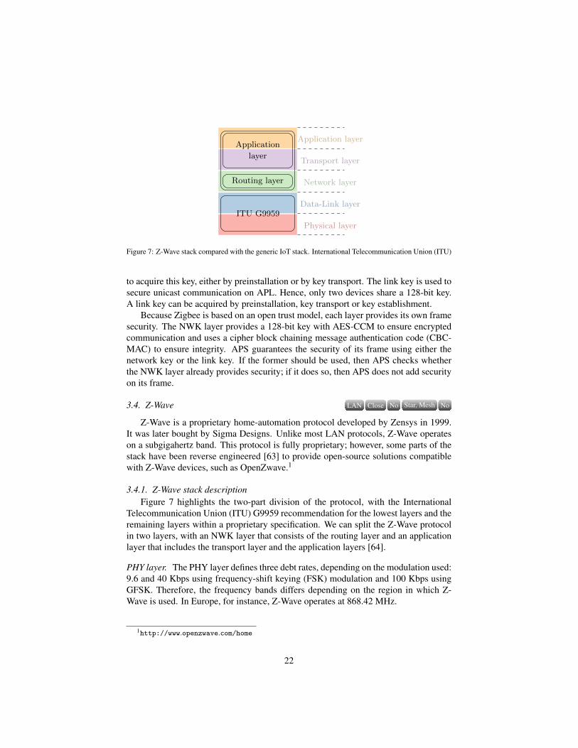
Figure 7: Z-Wave stack compared with the generic IoT stack. International Telecommunication Union (ITU)
to acquire this key, either by preinstallation or by key transport. The link key is used tosecure unicast communication on APL. Hence, only two devices share a 128-bit key.A link key can be acquired by preinstallation, key transport or key establishment.
Because Zigbee is based on an open trust model, each layer provides its own framesecurity. The NWK layer provides a 128-bit key with AES-CCM to ensure encryptedcommunication and uses a cipher block chaining message authentication code (CBC-MAC) to ensure integrity. APS guarantees the security of its frame using either thenetwork key or the link key. If the former should be used, then APS checks whetherthe NWK layer already provides security; if it does so, then APS does not add securityon its frame.
3.4. Z-Wave NoStar, MeshNoCloseLAN
Z-Wave is a proprietary home-automation protocol developed by Zensys in 1999.It was later bought by Sigma Designs. Unlike most LAN protocols, Z-Wave operateson a subgigahertz band. This protocol is fully proprietary; however, some parts of thestack have been reverse engineered [63] to provide open-source solutions compatiblewith Z-Wave devices, such as OpenZwave.1
3.4.1. Z-Wave stack descriptionFigure 7 highlights the two-part division of the protocol, with the International
Telecommunication Union (ITU) G9959 recommendation for the lowest layers and theremaining layers within a proprietary specification. We can split the Z-Wave protocolin two layers, with an NWK layer that consists of the routing layer and an applicationlayer that includes the transport layer and the application layers [64].
PHY layer. The PHY layer defines three debt rates, depending on the modulation used:9.6 and 40 Kbps using frequency-shift keying (FSK) modulation and 100 Kbps usingGFSK. Therefore, the frequency bands differs depending on the region in which Z-Wave is used. In Europe, for instance, Z-Wave operates at 868.42 MHz.
1http://www.openzwave.com/home
22

MAC layer. The MAC layer handles data exchange between devices and is responsiblefor such actions as frame acknowledgement, retransmission and packet origin authen-tication. The MAC frame is split into three parts; the MAC header (MHR), the MACservice data unit (MSDU) and the MAC footer (MFR). MHR contains important infor-mation, such as HomeID and SourceID, in which HomeID is a unique 4-byte numberidentifying a network and sourceID is an 8-bit number identifying a node within theZ-Wave network.
The MAC layer defines two types of devices in the network: the control deviceand the end device. Control nodes initiate commands and end devices respond to thesecommands. Moreover, a control device can act as a primary controller or a secondarycontroller. The primary controller is unique to each network and assigns HomeID andSourceID for each Z-Wave node during the enrolment process. It also stores and main-tains the routing tables for the entire network. The secondary controller contains thesame HomeID as the primary controller and maintains the routing table. End deviceswith batteries can also forward messages to nodes out of range of the control node.
Routing layer. The routing layer ensures the success of message transmission betweenthe control node and the end devices. Moreover, this layer specifies the maximumnumber of nodes as 232 and the maximum number of hops as four.
The routing layer is in charge of the routing features of the Z-Wave network. Itassigns the role of each device with a unique primary controller, which manages theentire network. It also determines which end devices participate in routing. Therefore,it is responsible for managing network topology and maintaining the routing table, withfeatures such as topology discovering and topology healing.
Application layer. The application layer depends on the Z-Wave application developer.Nevertheless, some behaviours are applicable to all devices. The application layer isresponsible for executing received commands. Commands are split into two classes:device and command.
The command class is related to a specific function, whereas the device class isrelated to the device. The device class is separated into three subclasses: basic, genericand special. The basic class identifies controllers and end devices with or withoutrouting capabilities. The generic class specifies the functions a device can performwithin its own role. Finally, the special class defines more specific features in devicefunctionality.
3.4.2. Routing in Z-WaveZ-Wave is a mesh networking protocol composed of a unique primary controller,
which manages the entire network, and up to 231 end devices, many of which haverouting capability. Moreover, Z-Wave uses a source-routed mesh network architectureto create the routing in the network, in which the routing table is handled by the pri-mary node and maintained by all control nodes. Hence, each control node can initiatecommunication with other nodes using the route stored in the routing table. A routecan pass a maximum of four nodes to reach the destination. If a route is unavailable,then the source node attempts to reach the destination via another route, continuingthese attempts until the path to reach the destination node is found. Then, the routingtable is updated by the control node to add or remove unused routes.
23

Application layer
Transport layer
Network layer
Data-Link layer
Physical layer
Hart App
WirelessHartproprietary
IEEE 802.15.4
Figure 8: WirelessHart stack compared with the generic IoT stack.
3.4.3. Security in Z-WaveZ-Wave comes without encryption by default, so all communications are sent in
plain text which facilitates interception, gathering and decoding of messages. Until thefifth generation of Z-Wave devices, the only security features were HomeID, whichuniquely identifies a network, and the explicit action required of the controller to adda new device to the network. In the latest generation (the 500 series), Sigma Designsintroduced a secure pairing process and provided hardware capabilities supporting the128-bit advanced encryption standard (AES-128). Once a device and the controller arepaired using the secure mode, a key is exchanged and used to encrypt further commu-nications. However, the latest generation must maintain backward compatibility witholder devices that lack the same level of security. In addition, even if the newest de-vices can use a secure mode and encryption, older devices require a no-security levelto operate. Therefore, legacy devices constitute an exploitable weak link.
3.5. WirelessHart NoMeshNoCloseLAN
The WirelessHart [65] protocol has been designed solely for the process automa-tion and manufacturing industries. It was created in September 2007 and relies onthe already-popular highway addressable remote transducer (HART) protocol. Thisprotocol was created to be suitable for IoT networks based on criteria such as powerconsumption and scalability just like all other IoT protocols. However, WirelessHartgoes beyond these other protocols, adding reliability and security as key features of theprotocol.
Figure 8 represents the stack of the WirelessHart protocol compared with our genericIoT stack. As explained earlier, the lower layer of WirelessHart is based on the openIEEE 802.15.4 standard. However, only the physical layer uses the IEEE standard; thedata-link layer relies on other mechanisms specific to WirelessHart.
WirelessHart implements its own TDMA data-link layer and uses the concept of asuperframe to provide better resistance to collision, as well as to provide deterministiccommunication.
According to [65], the network layer includes the transport layer and supports im-portant features that ensure reliability against interference and obstacles.
24

0x41AddressSpecifier
SequenceNumber
NetworkID
Dest.Address
SourceAddress
DLPDUSpecifier
Data Link LayerPayload MIC CRC
DLPDU header DLPDU footer
Figure 9: WirelessHart DLPDU structure.
The application layer is the same as that used in the HART protocol. Hence, itassures a perfect connection and compatibility between the two protocols, allowing awireless device to communicate with another device outside of the WirelessHart net-work without modification of the packets.
3.5.1. WirelessHart stack descriptionAs shown in Figure 8, WirelessHart defines its own data-link and network or trans-
port layers to adapt the existing HART protocol to wireless devices.
Data-link layer. In WirelessHart, this layer fills the important role of providing reliableand secure communication. These mechanisms are established by the data link protocoldata unit (DLPDU).
Moreover, as shown in Figure 8, the data-link layer differs from the data link pro-vided by the IEEE 802.15.4 standard. It introduces two features, frequency hoppingand channel blacklisting, to ensure reliability of communication.
Furthermore, TDMA used for the MAC layer improves resilience against collisionby allowing transmissions only within a strict time slot of 10 ms. Hence, multiple timeslots are grouped to from a superframe. A superframe is used to control the timingtransmissions.
The DLPDU of WirelessHart is detailed in Figure 9. The first byte is fixed to the0x41 for every frame of WirelessHart. The TDMA data-link layer specification definesfive types of frames:
• Acknowledgement DLPDU: This frame informs a sender of a nonbroadcast frameas to whether the frame was accepted.
• Advertise DLPDU: This frame contains all information needed to join the net-work. This frame corresponds to an invitation.
• Keep-alive DLPDU: This frame lacks a payload and is used for network timesynchronisation or access communication between neighbours.
• Disconnect DLPDU: This frame advices all device neighbours that a networkdevice is leaving.
• Data DLPDU: This is the only DLPDU that can contain information from ahigher layer in the payload. All other DLPDUs are exclusively used at the secondlayer.
25

HH
H
Automation Application area
GW
FD FD
FD
FDFD
A
FD
FD
Wired communicationWireless communication
H HostFD Field DeviceGW GatewayA Adapter
Figure 10: WirelessHart network structure.
Network and transport layers. The network layer is responsible of routing functional-ities, as well as addressing and delivery of data in a secure manner. The transport layercontrols reliable transmission and is included within the network layer [65]; it handlesthe security and reliability of the network.
The network manager is an important component of a WirelessHart network. Itis responsible for forming and configuring the network, scheduling communicationbetween devices, managing routing in the network and monitoring and reporting on thehealth of the network. There is only one network manager per WirelessHart network.
The network manager assures the functionalities provided by the network layer.All configurations of routing tables for the joining processes of network devices arehandled by the network manager. Furthermore, it is the only component that can updatethe routing tables. There are two ways to provide routing according to WirelessHartstandard [66].
3.5.2. Routing in WirelessHartWirelessHart network provides many types of topology [65], including star, clus-
ter and mesh. However, only the mesh topology is recommended for a WirelessHartnetwork. In this network architecture, each device has the capability to provide rout-ing, improving the scalability and reliability of the network. Moreover, a mesh topol-ogy provides redundant paths, assuring messages are routed around physical obstacles,broken links and various types of interference. All features are managed by a uniquecentral point called the network manager. Figure 10 illustrates the WirelessHart net-work structure.
WirelessHart provides three mechanisms to handle messages routing: graph, sourceand superframe.
Graph routing. All paths to route a message from a source to a destination using thegraph routing protocols are precomputed and form different graphs identified by a
26

graph identifier (graph ID). These paths are created by the network manager and down-loaded to each device. Thus, to send a packet, the source device includes in the headerthe specific graph ID determined by the destination. Hence, as each device proceeds tothe destination, it knows the next node to which it should forward the packet.
Source routing. Unlike the graph routing protocol, the source routing protocol is basedon an ad hoc protocol to create the route for messages. Thus, to send a packet, thesource device provides a list of devices through which the packet must travel. Whenthe packet reaches a node, it is forwarded to the next hop until it reaches the destinationnode. This protocol is used to provide network diagnostics.
Superframe routing. The superframe routing protocol is a variation of the graph rout-ing protocol. The packets are assigned to a superframe. Whereas graph routing pro-vides end-to-end routing paths in the network, superframe routing [67] uses the as-signed superframes based on a graph to provide communication opportunities.
3.5.3. Security in WirelessHartWirelessHart provides no choice as whether to use its security and disables the
option of turning it off. Security services are handled at the MAC and NWK layers,and each layer ensures security features.
The MAC layer provides hop-to-hop security and data integrity using the messageintegrity code (MIC) with AES-128 in CCM mode. The network layer uses a set ofkeys to ensure security for end-to-end communication including confidentiality anddata integrity. There are four keys:
• Public key: Used to generate MIC on the MAC layer by joining devices
• Network key: Shared amongst all devices and used to authenticate messages ona one-hop basis
• Join key: Unique to each network device and used to authenticate the joiningdevice during the joining process with the network manager
• Session key: Generated by the network manager, unique for each pair of devices,and used to ensure confidentiality and data integrity for unicast communication.
3.6. LoRaWAN NoCellularNoCloseWAN
LoRaWAN is a low power wide area network (LPWAN) intended for devices withconstrained resources operating on a long-range network. LoRaWAN is a MAC layerprotocol based on the long-range (LoRa) RF protocol (Figure 11) and maintained bythe LoRa Alliance.
3.6.1. LoRaWAN stack descriptionLoRaWAN [68] is a protocol developed to be used with the LoRa modulation tech-
nique. It provides to features suitable for LPWAN.
27

Application layer
Transport layer
Network layer
Data-Link layer
Physical layer
Application
(HTTP/MQTT)
LoRaWAN
LoRa
Figure 11: LoRaWAN stack compared with the generic IoT stack.
GatewaysEnd-devicesNetworkServers
ApplicationServers
LoRa RF
LoRa RF
ethernet, 4G ethernet, 4G
LoRaWAN
Figure 12: Architecture of a LoRaWAN network.
LoRa. LoRa is a proprietary radio modulation of the chip spread spectrum for LP-WAN. It uses the subgigahertz RF bands (868 MHz in Europe and 915 MHz in NorthAmerica). It provides a long communication range, typically around 5 km in urbanareas and up to 50 km in rural areas.
LoRaWAN. LoRaWAN defines the system architecture (shown in Figure 12) of thenetwork and the communication protocol. Moreover, LoRaWAN enables bidirectionalcommunication and thus defines three classes of devices:
• Class A: Class A must be supported by all devices. This is the class with thelowest energy consumption but with high downlink latency. Only two short win-dows for receiving downlinks are available after an uplink transmission of an enddevice.
• Class B: Class B devices include all class A windows for receiving downlinksand open additional windows for receiving downlinks at scheduled times. Agateway always sends a time-synchronised beacon to the end device. Thus, theserver always knows when the device is listening.
28

• Class C: Class C consumes the most energy of all classes. However, devicesfrom class C have continuously open windows for receiving downlinks exceptwhen the devices are transmitting.
Each class serves a particular application need and has optimised requirements for aspecific use. The difference amongst the three classes is the relationship between powerconsumption and latency. Class A has the lowest energy consumption but the high-est latency, whereas class C offers the lowest latency but needs a high-energy powersource.
3.6.2. Routing in LoRaWANThe architecture of a LoRaWAN network comprises four parts, as shown in Fig-
ure 12. From left to right, end devices communicate only with the gateway using LoRaRF protocol. Then, gateways centralise all messages from end devices before trans-mitting them to the network servers using high-data-rate technologies like Ethernetor long-term evolution (4G). In a similar manner, the network servers transfer data toapplication servers using high-data-rate technologies. LoRaWAN uses a cellular topol-ogy, also known as star of stars (Figure 2).
Moreover, each end device is associated with multiple base stations (or gateways).Hence, all data sent by the devices are forwarded by multiple gateways, without re-gard for redundancy or the integrity of the data. These verifications are applied by thenetwork server. The network server is in charge of the validation of various charac-teristics, such as data redundancy, integrity verification, receipt confirmation, emissionpower and even the debt adaptation.
3.6.3. Security in LoRaWANLoRaWAN defines three security keys that provide encryption and authentication in
the network: the network session key (NwkSKey), the application session key (AppSKey)and the application key (AppKey). Each key has a 128-bit length. The NwkSKey isused to communicate at the network level (device to network servers). This key isalso used to compute the MIC of each message sent on the network to ensure its in-tegrity. The AppSKey is used to encrypt messages at the application level. This meansthat only the end device or the application server can encrypt and decrypt the mes-sages. NwkSKey and AppSKey are unique to each device and to each session and aregenerated according to the device activation method, either dynamically or statically.The over-the-air-activation (OTAA) method uses the AppKey and obtains other re-sources from the server to dynamically derive the set of keys. The static method (ABP)uses a preshared AppKey to derive the two session keys. Based on the method used,NwkSKey and AppSKey are regenerated whenever the device is dynamically activated(OTAA); otherwise, the sessions keys remain the same until changed.
3.7. Sigfox NoCellularNoCloseWAN
Sigfox is another LPWAN technology that was created before LoRaWAN in 2009.These two protocols are intended for long-range communication and resource-constraineddevices but provide different solutions to achieve their goals. Sigfox acts as an operator
29

Application layer
Transport layer
Network layer
Data-Link layer
Physical layer
HTTP/MQTT
Frame
PHY
MAC
Figure 13: Sigfox stack compared with the generic IoT stack.
that owns its network; hence, a subscription to the Sigfox operator is required to usethe network.
Sigfox is a proprietary protocol that includes all layers except the application layer(as shown in Figure 11).
3.7.1. Sigfox stack descriptionSigfox uses ultranarrowband radio technology and as LoRaWAN operates on the
ISM bands (868 MHz in Europe). A specific feature of Sigfox is a payload length ofonly 12 bytes. The protocol is designed to be used with a short payload. Moreover, theuse of the ISM band restrains the number of packets sent each day. Hence, the limit onpackets per device in Sigfox is 14 messages per day. Thus, the technology is mainlyused by applications that do not require a continuous flow of data.
According to Figure 13, the Sigfox stack includes three parts: the PHY layer, theMAC layer and the frame layer.
PHY layer. The role of the PHY layer is the same as for all other protocols: handlethe protocol signal. In other words, the PHY layer manages RF modulation. Sigfoxuses two modulation algorithms, depending on the type of communication: differentialBPSK (DBPSK) modulation for uplink and GFSK modulation for downlink.
This layer is also in charge of the bit rate and the operation frequencies, dependingon the country in which Sigfox is used. For example, in European countries, the Sigfoxprotocol operates on the 868-MHz band at a bit rate of 100 bps.
MAC layer. The MAC layer is in charge of the device’s authentication in the network.To do this, the MAC layer adds fields for authentication, as well as other standardprogrammes such as an error-detection code (cyclic redundancy check). Moreover, theSigfox protocol removes all signalling from the MAC layer and devices. This meansdevices are not synchronised with the network.
Frame layer. The frame layer includes the transport and network layers from the genericIoT stack. The frame layer must satisfy the functionalities of these two layers. In otherwords, it acquires the payload provided by the application layer and generates the radioframe that is useful for the lower layers. Therefore, the frame layer adds a sequencenumber systematically into the frame.
30

GatewaysEnd-devicesSigFoxCloud
ethernet, 4G
Figure 14: Architecture of a Sigfox network.
3.7.2. Routing in SigfoxThe routing in Sigfox is similar to the routing in LoRaWAN. The topology of a
Sigfox network is also a star of stars, as shown in Figure 14. However, Sigfox uses acloud platform to transfer the processing power, rather than transferring in the devices,to reduce the energy consumption.
Devices enable bidirectional communication, but downlink communication canonly be started by the device. Then, a short window is enabled for the downlink.Moreover, like LoRaWAN, Sigfox devices are not associated to a unique base station.The data can be sent through multiple antenna to reach the cloud platform on whichthe data will be used.
3.7.3. Security in SigFoxSigfox devices are provisioned with a unique symmetrical AES-128 authentication
key. This key is derived to provide a MAC for each message to ensure authenticity andintegrity. In addition, a sequence counter avoids replay attacks. However, there is noconfidentiality mechanism; by default, all messages are sent in plain text. Therefore,applications must implement their own end-to-end encryption to protect critical infor-mation. Sigfox clearly relies on security through obscurity, providing a subpar securityquality, while denying access for research on the proprietary protocol [69].
4. IoT attack study
IoT devices are embedded devices that include operating system and system soft-ware. Moreover, these devices are interconnected and use wireless communicationto exchange messages. These features all imply the likehood of IoT security threats,which can be evaluated using the traditional confidentiality, integrity and availabilityprinciple:
• Confidentiality: Capacity to hide information from those who are not authorisedto view it.
31

• Integrity: Capability to ensure that transmitted data are not tampered with ormodified from the source to the destination
• Availability: Capacity of information to always be readily accessible by entitiesauthorised to access it. For the rest of this paper, when we talk about attacksagainst availability, we only refer to attacks implemented by an attacker, notthose caused by natural disasters.
We consider IoT systems to be networks of devices with a specific architecture, ortopology. Every device can exchange data with every other device through commu-nication using one or multiple protocols. Moreover, even though there can be manysoftware issues in IoT devices, we focus on vulnerabilities against communication andprotocols. Software issues are usually not specific to IoT but rather are classical ITproblems.
Observe andmanipulate packets
Focus on packets
Alter the topology
Focus on protocols
Compromisethe system
Focus on the system
Figure 15: IoT kill chain.
We propose in Figure 15 an attack pattern that an attacker could follow to gain fullcontrol of an IoT system. This kill chain is split into three parts: packets, protocoland finally the system. The first step is focused on devices and more precisely, onsent and received messages (Section 5). The second step of the kill chain concernsthe protocol and possible ways to alter the topology to control a subnet or the entirenetwork (Section 6). The last step describes attacks against the whole system after ithas been compromised (Section 7).
Table 3 summarises all attacks presented and detailed in this sections for all pro-tocols. When an attack is possible in theory or practically for each protocol, the cellis filled with one or more references. Empty cells show attacks for which there is notenough documentation available, either on the protocols or on the attack, to be able toidentify whether the attack is feasible. Finally, when we think that an attack cannotbe achieved, we place a %in the corresponding cell. The assumption of whether anattack is possible if no reference is available depends on analysis of the protocols andour experience.
32

AttacksProtocols
OS4I BLE ZigBee Z-Wave WirelessHart LoRaWAN SigFox
Pack
ets Passive cryptographic [70] [18, 71, 72] [73] [17] [19] [74, 75] [69]
Active cryptographic [76] [77] [73, 78, 79] [17] [74, 75] [69]
Prot
ocol
s
MITM [77] [20] [80]
Flooding [76, 81, 82] [73] [19] [75]
Sybil [82] % [83] % % %
Spoofing [84] [73] [19] [74, 75]
Wormhole [85, 82] % [20] [19] [86]
denial-of-service (DoS) [87] [88, 79] [80, 17] [19] [74, 75]
Syst
ems Sinkhole [82] % [89, 90] % %
Selective forwarding [82] % [20] [19] % %
Table 3: Attacks summary.
5. Focus on packet security
Packet security is the first element in the kill chain as shown in Figure 15. Thisstep consists of retrieving information or potentially gaining control of a device. Asdescribed earlier, we deliberately only consider vulnerabilities against communicationand protocol and not software exploitation. Thus, this step describes attacks againstcommunication from and to a device – in other words, cryptographic attacks. Wedistinguish passive cryptographic attacks from active ones.
Passive cryptographic attacks consist of extracting secrets or confidential data fromintercepted frames without emitting a message. Because no action is performed withinthe network, there is no risk of altering the integrity or availability of the network.Instead, passive cryptographic attacks compromise confidentiality by stealing informa-tion from devices through eavesdropping.
With active cryptographic attacks, an attacker can modify messages transmittedthrough the network. The attacker can also inject traffic by forging or replaying framesto disturb the network. Hence, an active attack aims to compromise the three principlesof confidentiality, integrity and availability.
5.1. Passive cryptographic attacksWireless communications are natively prone to traffic interception. Encryption is
one solution to ensure that transmitted data are protected against unauthorised access.We distinguish four levels of cryptographic attacks, which we characterise as attackingno cryptography, ugly cryptography, bad cryptography and good cryptography.
5.1.1. No cryptographyMany IoT systems use unencrypted communications to communicate. This makes
it easy to gain information from captured packets. In this case, no specific actionsare required from the attacker to obtain the information contained in a message: theattacker examines the wireless communications and extracts information without com-puting actions.
33

5.1.2. Ugly cryptographyWe consider the cryptography to be ugly when communications are encrypted with
weak cryptography, such as an old algorithm or small keys, and are thus easily break-able.2 In this case, an attacker can obtain all plain texts from encrypted communi-cations using limited computational power. Communications with ugly cryptographyshould be considered equivalent to those that are unencrypted.
5.1.3. Bad cryptographyWith bad cryptography, the algorithms that encrypt the payloads use state-of-the-
art standards, but the developers relied on an ad hoc implementation or deployment ofthese algorithms. Often, these implementations do not tackle every aspect necessaryto provide the expected level of security. Weaknesses may lie in key generation, keyexchange or key encryption, etc.
In [17], the authors, after analysis of the frame encryption and authentication al-gorithm in a Z-Wave network, were able to find a vulnerability that allowed them totake the control of a smart door. It appears that the encryption key was not sent inpain text. Hence, the first thing an attacker must determine is how the key is encrypted.The authors assumed that the key was generated by a pseudo random number generator(PRNG) provided by the Z-Wave chip and then encrypted with a hard-coded temporarydefault key in the chip’s firmware. They found that this key value was 16 bytes of zeroand they were able to retrieve the plain text of the key.
5.1.4. Good cryptographyIn good cryptography, the algorithms used to encrypt communications are strong
enough to be hard or impossible to break in a finite time. This cryptography relieson a standard algorithm, such as AES, with good parameters, sufficient key size, validimplementation and proven deployment. Here, an attacker may not to be able to findthe plain text of the payload, yet it may still be possible to identify patterns that allowthe attacker to gain some information.
5.2. Active cryptographic attacks
Good implementation of a cryptographic standard is not always enough to ensureperfect security of data. Other mechanisms are important to secure communicationwithin a network. However, to test whether these mechanisms are present, an attackermust inject packets into the network or tamper with existing packets in the network.
5.2.1. Same-nonce attacksIn cryptography, nonces are random numbers that must be used only once. These
numbers can be generated from a random or a pseudorandom generator. The main goalof these nonces is to avoid the reused of a frame in a replay attack. A same-nonce attackallows an attacker to retrieve partial information regarding plain texts from cipher textmessages.
2https://www.wired.com/story/hackers-steal-tesla-model-s-seconds-key-fob/
34

This attack is possible in Zigbee [91, 79, 78] and 6LoWPAN [76], mainly becauseof the security provided by IEEE 802.15.4 at the MAC layer [23]. The cipher suiteused in IEEE 802.15.4 to encrypt payloads is AES-CTR. Hence, the payload is XORedwith a keystream generated from a nonce and a preshared key. The nonce is derivedfrom the device’s extended address and the frame counter. When two payloads areencrypted with the same keystream, it is possible to decrypt them. Thus, let’s considertwo payloads P and P′, their encrypted versions C and C′ and the K keystream. Wehave C⊕C′ = (P⊕K)⊕ (P′⊕K) = P⊕P′. This conclusion is possible if the counterdoes not change between two frames.
In [76], the authors identified that when a device could not receive the expectedbeacon in time, the device rebooted. This unexpected behaviour reset the counter tozero but kept the same extended address and preshared key. Thus, in waiting for thegood frame, it was possible to obtain several frames with the same keystream.
5.2.2. Replay attacksA replay attack consists of simply resending intercepted frames to the same device
a moment later. The consequences of a replay attack are diverse, such as commandreplays and data retransmissions. Therefore, a replay attack does not allow an attackerto gain new information from the intercepted frame; instead this attack represents thusan integrity issue (not a confidentiality one).
In [76], the authors used the same vulnerability as for a same-nonce attack: counterreset. Just as in the same-nonce attack, when the device rebooted, its counters werereset. Thus, it was possible for an attacker to replay an intercepted frame with the rightframe number.
In the same manner, in [78], the authors showed how they could switch on a light byreplaying a frame. In Zigbee, when a counter reaches the maximum number, it is resetto zero but neither the nonce nor the key used to generate the keystream is changed.Thus, to replay a frame, the attacker just had to wait until the counter was reset.
5.2.3. Malleability attacksA malleability attack is a combination of the two previous attacks: replay and same-
nonce. In other words, in a malleability attack, an attacker forges a new frame, encryptsit and sends it through the network. In a same-nonce attack, the attacker retrieves plaintext and with the plain text and its cipher text, can retrieve the keystream using an XORoperation: C = P⊕K→ K =C⊕P, where C is the cipher text, P is the plain text andK is the keystream. With the keystream, it is possible to forge a new encrypted frame.Instead of using a replay attack, an attacker can send the new forged frame with thesame counter.
In [76], the authors took advantage of counter reset after device reboot to use same-nonce attacks and gain large amounts of cipher text encrypted with the same keystream.In this way, they could retrieve many plain text frames. Using the XOR operationbetween plain text and cipher text, they retrieved several keystreams with differentcounters. Thus, they had the capability to forge new frames with the keystreams. Then,instead of replaying an intercepted frame to pull off a replay attack, the authors senttheir forged frames with the corresponding counter through the network.
35

A
E
B
Expectedcommunication
Man-In-The-Middle
Figure 16: MITM attack.
6. Focus on protocol security
After the first step of the kill chain shown in Figure 15, an attacker was able toretrieve information or potentially take control of a device. The next step is to spreadthat control or simply increase the privileges. In an IoT system, this consists of alteringthe topology to take control of some part of the network using protocol weaknesses.
6.1. MITM attack
The MITM attack is well known in network and communication protocols. It con-sists of secretly intercepting, altering and relaying information between two devicesthat believe they are communicating with each other. Figure 16 represents the tradi-tional scheme of an MITM attack, in which device A and device B are the two legiti-mate devices and device E is the attacker attempting to intercept the traffic.
In [92], the author presented a tool to perform an MITM attack against devicesusing the BLE protocol to communicate. During the presentation, he details the re-quirements needed to perform this attack and how easy it is to implement it. The attackconsists of creating two fake devices, one acting as the central device and one as adummy. The central device will connect to the legitimate device, and the dummy isa perfect copy in term of features and characteristics of the legitimate device. Thedummy and the central device must be connected to each other to relay communica-tion. The most important thing is timing. To perform this attack, it is mandatory thatthe attacker connect the central device to the legitimate device before the user can doso. Then, the attacker must copy the device to catch the user connection and relayinformation between the legitimate device and the user through the central device andthe dummy. Therefore, the user believes communications with BLE-enabled deviceis occurring normally, but instead, all communications are being intercepted, analysedand even altered. Depending on the tool used to perform the MITM attack, different ca-pabilities are available such as a replay attack or on-the-fly communication alterations.
6.2. Flooding attack
A flooding attack consists of sending a succession of requests to a particular de-vice. This action attempts to consume enough of the device’s resources to limit or stop
36

NMD1 D2
T
A
D4
D6D5 D7
D8
(a) Network before the disconnect attack
NMD1 D2
T
A
D4
D6D5 D7
D8
(b) Network after the disconnect attack
Figure 17: Network before (a) and after (b) the disconnect attack.
its activity. Furthermore, this attack can be divided into multiple attacks with differ-ent consequences, such as the Hello flood attack [82]. Generally, a flooding attack isconsidered the simplest attack leading to DoS [93, 94].
In [76], the authors flooded a 6LoWPAN sensor to make it lose synchronisationwith the PAN coordinator. Device reboot was not an anticipated behaviour, but theyfound that sensors, because of the flooding attack, could not receive the expected bea-con from the PAN coordinator, giving rise to loss of synchronisation. Thus, the sen-sor had to resynchronise with the PAN coordinator. By capturing the IEEE 802.15.4frames sent to the coordinator, it was possible to gather useful information, such as theextended address of the device. Moreover, it appears that this flooding attack affectedthe PAN coordinator in a same manner, forcing it to reboot. Hence, this attack allowednot only the disruption of the sensor but also the gathering of information required tolead other attacks.
6.3. Spoofing attack
A spoofing attack is a well-known network security attack. It consists of an attackersuccessfully masquerading as another device by tampering with the target’s data. In ourcase, a spoofing attack consists of using a controlled device to spoof a legitimate deviceinside a network to implement different actions, such as disconnecting or sending falseinformation.
In [95], Bayou et al. implemented a spoofing attack to disconnect a node. Thisattack was based on the DLPDU structure, especially the disconnect type of DLPDU.This structure was created at the data-link layer and secured by the network key (sharedby all network devices). According to the WirelessHart standard, this type of messageallowed the device to inform its neighbours that it was leaving the network. Thus,each neighbour removed all information about the departing device from its neighbourlist and deleted all links towards or from it. Then, the neighbours reported this devicedisconnection to the network manager, which updated the routing tables.
37

To implement a disconnect attack, the attacker must spoof the identity of a legiti-mate node by forging a false disconnect DLPDU with the source address of the targeteddevice and then send it to the network manager. Afterward, the network manager willremove all links of the targeted device from its routing table. To perform this attack,the attacker needs a preparation state to gather information about the targeted device.The short address and the long address of the device are mandatory. Furthermore, theattacker’s device must be synchronised with the network’s current time because of theuse of TDMA (see Section 3.5 for more details). This action can be done as follows:
• Compromise a legitimate device that received its own schedule from the networkmanager.
• Use the retry slot to send the disconnect packet to each target’s neighbour one byone until the parent is found.
In [95], the authors used the join link to send the disconnect DLPDU. This linkis normally used by new devices to join the network. But to accelerate the joiningprocess, WirelessHart allows advertisement DLPDU to be sent on the join link. Thismessage contains joining information and is sent periodically through the entire net-work. Hence, the attacker’s device must wait for an advertisement DLPDU from thetarget’s parent and use the join link to send the disconnect message.
Figure 17a represents the network before a disconnect attack, in which the red nodeis the attacker’s device A, the green node represents the target T and the blue node isthe network manager NM. During this phase, A acts as a normal device. As soon asthe attack is launched, A enters search mode to gather information about the target andwaits for an advertisement message. When the target parent (D2 in Figure 17) sendsit, A forges a disconnect DLPDU, sets the short address of T as the source addressand sends it to D2. After receipt and validation of this packet with the network key,D2 removes the sending device from its neighbour list and forwards the informationto NM. Thus, all links with T are removed and this device is no longer considered adevice of the network (as shown in Figure 17b). All packets from T , whether its ownor those of its children, are dropped. At this point, two distinct networks exist with nocommunication between them.
6.4. Sybil attackThe sybil attack [96] aims to forge and use numerous identities from a single mali-
cious node. It has been widely used to target distributed reputation systems but is alsoa threat for distributed routing protocols. With numerous created identities, an attackerholds a large amount of influence in the network, which might affect the network’seffectiveness and even the chosen paths of distributed service or multipath routing.
This attack is only possible if the network does not run a trusted central authoritythat verifies each identity before including it in the network. This lack of control is atraditional weakness of wireless ad hoc and sensor networks.
In [97], Medjek et al. described how an attacker could throw a sybil attack againstRPL-based network. They used and took advantage of an RPL feature to add a nodeto the network. Two methods exist to join an RPL network: waiting for DODAG in-formation object (DIO) messages or sending DODAG information solicitation (DIS)
38

messages. These DIS messages are similar to router solicitation messages, allowing anode to discover DODAG information from its neighbours by soliciting DIO messages.Once an attacker receives DIO messages, the attacker fills a DODAG destination ad-vertisement object (DAO) message with a crafted node identifier and its parent address.The attacker then broadcasts the DAO message to be advertised by the node neighbourto update the routing table and the parent list. With this method, the attacker can createmany nodes with forged identities and add them to an RPL network.
6.5. Wormhole attack
In wormhole attacks [98], the attacker uses a tunnel between two malicious nodesto relay messages from zone A to zone B faster or with fewer apparent hops thanwould be done using the expected multihop protocol. The attacker can use a wired linkbetween the two relays or even fast wireless connectivity. This manipulation allows theattacker to be seen as the best route between these two zones and thus to relay mostpackets between them. The attacker then gains privileges that allow eavesdroppingor manipulation of the routed packets. This attack is highly dangerous, because itdoes not require known cryptographic keys, thus, this attack is effective even if thecommunication network provides confidentiality and integrity.
In [85], Perazzo et al. presented an implementation of a wormhole attack againsta 6LoWPAN network built upon IEEE 802.15.4 and using the routing algorithm RPL.The first step of the attack was to enable communication between devices too distantto communicate directly. This was possible using two malicious nodes, mn1 and mn2,as gateways, one in each area and connected with a high-speed connection, such as theInternet or a local network. Another important point is the method of delivery for ACKpackets to ensure that devices used the tunnel as shortest path to reach the destination.The time between emission and receipt of an ACK packet must be shorter than thetimeout. Therefore, using a specification of IEEE 802.15.4, in which ACK packetsmust not be authenticated, the authors used a programme to reply to an ACK responsefor any unicast frames received in both malicious nodes. The attack was thus led asfollows: mn1 intercepted DIO broadcast messages from zone A and relayed them tomn2, which replayed the messages in the other zone. Each device receiving the DIOmessage responded to the sender with a unicast frame. These frames were interceptedby mn2, and then it automatically replied with a forged ACK packet before transferringthe unicast frame to mn1. In this way, the attacker was able to reduce the number ofhops between the two devices and to control the traffic flow passing through the createdtunnel.
7. Focus on system security
After the second step of the kill chain shown in Figure 15, an attacker was able toalter some parts of the topology. The attacker can then try to alter the functioning ofthe entire system.
39

7.1. Sinkhole attacks
A sinkhole attack consists of creating a centralised point from a malicious node andluring all traffic from a particular area. Furthermore, all devices from this area mustcommunicate through this malicious device. This attack makes it possible to performmany other attacks, such as selective forwarding.
To make the malicious device the centralised point for all other nodes, it must beseen as a good choice by respecting the routing algorithm. Depending on the algorithmused, the criteria to be an attractive node may differ. But a high-quality route andlow-latency transmission are two points that allow it to become the central point of allcommunication. A perfect way to reach this aim is to spoof or replay an advertisementfor a high-quality route to another device.
This attack is easy to implement in an RPL network [82] because of its particulararchitecture in the DODAG form. The attacker can intercept a DIO control messageand change the advertised rank contained inside. The rank field identifies the positionof the router inside the graph. Moreover, the attacker can remove the delay usuallyused to reduce network congestion. These two modifications increase the reputation ofthe malicious node, and force the other devices to send their traffic through this node.
7.2. Selective-forwarding attacks
A selective-forwarding attack takes place in networks with the assumption that anyactives nodes are faithful when they forward packets. The selective-forwarding attackconsists of allowing only wanted traffic to move through malicious nodes. The remain-ing packets are dropped, ensuring that they are not propagated.
There are two methods of implementing this attack. The first method is to usemalicious nodes, becoming a black hole and forcing them to refuse to forward everypacket. However, this behaviour may lead legitimate nodes to seek another route tosend their packets. Hence, the second, more effective method consists of not droppingevery packet but choosing only those the attacker wants to forward.
This attack, when applied against RPL [82], consists of letting the malicious nodesdrop all packets except packets relative to the protocol. Hence, the attack insists thatonly packets destined for the malicious node or containing RPL information are notdropped. In this way, the protocol works normally, but application data can be lost.The RPL self-healing and self-management mechanisms cannot correct the maliciousbehaviour even after running for 24 hours [82].
40

Generic approach to describefundamental security issues
of IoT networks
Generic approach tocomparing IoT stacks
(Section 2)
Comparison criteria(Section 2.1)
Range
Interoperability
Security practices
Topology
Openness
Generic IoT stack(Section 2.2)
IoT protocols(Section 3)
OS4I
BLE
Zigbee
ZWave
WirelessHart
LoRaWAN
Sigfox
Generic approach todescribe IoT attacks
(Section 4)
Focus on packets(Section 5)
Passive cryptographic attacks
Active cryptographic attacks
Focus on protocols(Section 6)
MITM
Flooding
Sybil
Spoofing
Wormhole
Focus on system(Section 7)
Sinkhole
Selective forwarding
Figure 18: Summary of the generic approach to describe fundamental security issues of IoT networks.
8. Discussion
In this section, we discuss the lessons we learned from our approach to describefundamental security issues of IoT networks and identify several initiatives for futurework, which may improve the security of IoT networks.
8.1. Approach to describe fundamental security issues of IoT networks: lessons learned
Figure 18 outlines the approach we used to describe the security issues of IoTprotocols. From this approach, we pinpointed two challenges we tackled in this survey.
The first challenge concerned the generic approach to compare different IoT stacks.From this challenge, we highlighted the difficulty of identifying common criteria anddefining an abstract structure to efficiently compare different IoT protocol stacks. Thesignificant related work presented in Section 1.3 emphasises the difficulty to charac-terize IoT protocol stacks generically. Depending on the area of activity, usages andapplications, the characteristics and the specificities of IoT protocol stacks differ [99].
41

For instance, the Sigfox protocol, mainly used for wide-area communications with lowdata-rate, uses a DBPSK modulation for uplink and operates on the 868 MHz band,whereas the BLE protocol, used for short-range communications with high data-rate,uses a GFSK modulation and operates on the 2.4 GHz band. The availability of thedocumentation and specifications of every protocol is variable and accentuates the dif-ficulty to provide a common approach to compare them. We tackled this challenge withthe proposition of a generic IoT stack and five comparison criteria, which are used topresent and analyse different IoT protocol stacks in a similar formalism. This proposi-tion captures the fundamental characteristics of the IoT paradigm and, as such, shouldbe able to capture future IoT protocols: we would need to classify these novel proto-cols according to the proposed criteria and, as our generic stack divides the protocolsinto fundamental IoT applications layers, we should be able to map future (versions of)protocols onto this stack.
The second challenge addressed the generic approach to describing IoT attacks.As described throughout this paper, published attacks against IoT protocols are alwaysprotocol-specific. We can explain this result with multiple points of view. The mul-titude of protocols makes the analysis of each attack against every protocols hard andtedious. Furthermore, regarding the protocol, the condition to realize the attacks couldbe hard or even impossible to reproduce in practice. For instance, two devices are re-quired to perform a MITM attack in BLE, whereas an infrastructure must be deployedto ensure that Zigbee devices can communicate to finally perform the MITM attack.This constraint makes the generic analysis of attacks complicated. Finally, the avail-ability and the accessibility of details about the security mechanisms differ with everyIoT protocol stack, making the generic analysis of attacks hard for every IoT protocolsstacks. We tackled this challenge with a killchain divided into three parts: attacks fo-cusing on packets, attacks focusing on protocols and attacks focusing on systems. Wewere able to analyse each attack in relation to the formalism proposed for the genericIoT stack. Hence, we were able to inventory similar attacks on different protocols,link them, estimate which attacks could be similarly done against another protocoland which protocols were inherently resistant to specific attacks. In the event of anovel attack against a given protocol, we should be able to classify it in the killchain(packets, protocols, systems), identify whether it is an adaptation of an attack againstanother protocol or a fundamentally innovative one and, if it is an innovative one, anal-yse whether it could be used against other IoT protocols. Moreover, when new IoTprotocols will arrive, once they are analysed through the lens proposed in the first part(comparison criteria, generic stack), we should be able to rapidly evaluate which vul-nerabilities exist or, to the contrary, are mitigated.
8.2. Perspectives to improve the security of IoT networks
We can exhibit some root causes to these security problems. First, although pro-tocol stacks evolve, commercial imperatives imply that they must keep some compat-ibility with already-deployed objects, which causes legacy security limitations [100,101]. This problem may be mitigated by isolating parts of the system or by pro-moting open-source software or hardware, which usually carries fewer legacy require-ments [102, 103], allowing old objects to be upgraded. Second, objects often cannot be
42

upgraded [104], and for those that can vendors usually provide inadequate security pol-icy upgrades [105] (which either are provided too rarely or are not provided for enoughtime, considering the expected duration of these objects). We strongly believe thatIoT vendors need to foster communication with security researchers, rather than tryingto mute them. These collaborations can lead to open specifications and collaborativebug bounties [106]. Third, commercial pressure puts usability before security [107],and any actor who would like to change this process would probably face lower salesthan those of its competitors. A penetration testing approach [108] may yield excit-ing results by emphasising, for a given deployment, security measures that should notbe ignored. Finally, despite providing similar functionalities, there are too many het-erogeneous protocols. Security researchers and operator endeavours are thus scatteredamongst systems, instead of uniting their forces. We need a common framework tomutualise security efforts and facilitate exchange amongst communities working ondifferent protocols.
Starting from this work, we identify that a new method might be defined to ensurethe same security mechanisms regardless of the protocol stack used. Defining this newmethod raises several new interesting research and methodological points:
• Identifying common security criteria by drawing up a list of security featuresamongst all protocols to establish a global base that could be applied for eachprotocol stack. Existing works [109, 110, 111] provide classifications and tax-onomies of security features that could be applied generically. However, theseworks are focused on a specific aspect or a specific application of the IoT andnot on IoT protocol stacks. These works may be worth to be pursued to providea taxonomy of security criteria suitable for every IoT protocol stacks.
• Harmonising security mechanisms by finding a solution to apply them regardlessof the protocol stack used. A solution may be to define a certification that eachprotocol must apply [112, 113]. This certification, relying on common securitycriteria, should be generic enough to suit the maximum IoT protocol stacks andcover the largest field of applications. We could imagine another solution, suchas a framework [114] that identifies which security mechanisms must be appliedaccording to the application domain targeted.
• Ensuring a constant security level, even if protocol stacks and deploymentsevolve. IoT environments are indeed much more subject to evolutions in timeand space [115, 116]. It means - in time - guaranteeing a regular follow-up ofevery version deployed for a protocol to ensure the same level of security. Sys-tematic security regression testings need to be defined and need to also evolvewith new IoT protocols. They should, for instance, avoid compatibility issuesopening security breaches from two different versions of the same protocol. Orthey should, for instance, avoid two different protocols known to be individuallysafe, but opening a security breach when combined. It also means - in space -to be able to correlate a physical area and a security level. Deploying a new IoTdevice, a crash or misbehaviour of a device, should affect the security level andbe considered as a potential intrusion. Automatic analysis of the device trafficshould be able to dynamically qualify the level of security of the overall deployed
43

IoT architecture. IoT environments require intrinsic flexibility to easily deployanything, anywhere, anytime, but raise this new challenge to define new flexiblesecurity frontiers and guarantees in space and time.
Tomorrow’s IoT will be multiprotocol, mixing various complementary systems de-ployed at different moments, and will have to deal with both the legacy of a commonprotocol and a range of different protocols. Analysis on the scale of a unique protocolwill no longer be pertinent.
9. Conclusion
This survey aims to detail the many challenges to the security of IoT. We define ageneric approach to compare major IoT protocol stacks, using a generic stack based onthe OSI model. We base our comparison on five criteria: range, openness, interoper-ability, network architecture and security practices. We also suggest a kill chain againstIoT networks, with multiple attacks that are not specific to a given protocol. Finally,we propose a comprehensive, structured and generic study of IoT security issues.
References
[1] A. Al-Fuqaha, M. Guizani, M. Mohammadi, M. Aledhari, M. Ayyash, Internetof things: A survey on enabling technologies, protocols, and applications, IEEECommunications Surveys & Tutorials 17 (4) (2015) 2347–2376.
[2] L. Da Xu, W. He, S. Li, Internet of things in industries: A survey, IEEE Trans-actions on industrial informatics 10 (4) (2014) 2233–2243.
[3] J. Gubbi, R. Buyya, S. Marusic, M. Palaniswami, Internet of things (iot): Avision, architectural elements, and future directions, Future Generation Comp.Syst. 29 (7) (2013) 1645–1660.
[4] S. Sicari, A. Rizzardi, L. A. Grieco, A. Coen-Porisini, Security, privacy and trustin internet of things: The road ahead, Computer networks 76 (2015) 146–164.
[5] Gartner, Gartner says 5.8 billion enterprise and automotive iot endpointswill be in use in 2020, https://www.gartner.com/en/newsroom/press-releases/2019-08-29-gartner-says-5-8-billion-enterprise-and-automotive-io, accessed on 17 June 2020 (2019).
[6] J. Lin, W. Yu, N. Zhang, X. Yang, H. Zhang, W. Zhao, A survey on internet ofthings: Architecture, enabling technologies, security and privacy, and applica-tions, IEEE Internet of Things Journal 4 (5) (2017) 1125–1142.
[7] M. J. Kaur, P. Maheshwari, Building smart cities applications using iot andcloud-based architectures, in: International Conference on Industrial Informat-ics and Computer Systems (CIICS), IEEE, 2016, pp. 1–5.
44

[8] T. H. news, How drones can find and hack internet-of-things devices fromthe sky, https://thehackernews.com/2015/08/hacking-internet-of-things-drone.html, accessed on 21 August 2019 (2019).
[9] T. H. news, Z-wave downgrade attack left over 100 million iot de-vices open to hackers, https://thehackernews.com/2018/05/z-wave-wireless-hacking.html, accessed on 21 August 2019 (2019).
[10] T. H. news, Blueborne: Critical bluetooth attack puts billions of devices at risk ofhacking, https://thehackernews.com/2017/09/blueborne-bluetooth-hacking.html, accessed on 21 August 2019 (2019).
[11] T. H. news, Hackers could turn LG smart appliances into remote-controlledspy robot, https://thehackernews.com/2017/10/smart-iot-device-hacking.html, accessed on 21 August 2019 (2019).
[12] R. Hallman, J. Bryan, G. Palavicini, J. DiVita, J. Romero-Mariona, IoDDoS -the internet of distributed denial of sevice attacks - A case study of the miraimalware and iot-based botnets, in: IoTBDS, 2017.
[13] J. Radcliffe, Hacking medical devices for fun and insulin: Breaking the humanSCADA system, in: Black Hat, 2011.
[14] T. H. news, Hackers can remotely access syringe infusion pumps to de-liver fatal overdoses, https://thehackernews.com/2017/09/hacking-infusion-pumps.html, accessed on 21 August 2019 (2019).
[15] T. H. news, Casino Gets Hacked Through Its Internet-Connected Fish TankThermometer, https://thehackernews.com/2018/04/iot-hacking-thermometer.html, [Online; accessed on 21 August 2019] (2019).
[16] T. H. news, How to Hack Smart Bluetooth Locks and IoT Devices — Checkthis Out, https://thehackernews.com/2016/09/hacking-bluetooth-locks.html, [Online; accessed on 21 August 2019] (2019).
[17] B. Fouladi, S. Ghanoun, Security evaluation of the z-wave wireless protocol,Black hat USA 24 (2013).
[18] M. Ryan, Bluetooth: With low energy comes low security, in: 7th USENIXWorkshop on Offensive Technologies, WOOT, USENIX Association, 2013.
[19] S. Raza, A. Slabbert, T. Voigt, K. Landernäs, Security considerations for theWirelessHART protocol, in: International Conference on Emerging Technolo-gies and Factory Automation (ETFA), IEEE, 2009, pp. 1–8.
[20] P. Baronti, P. Pillai, V. W. C. Chook, S. Chessa, A. Gotta, Y. Hu, Wireless sensornetworks: A survey on the state of the art and the 802.15.4 and zigbee standards,Computer Communications 30 (7) (2007) 1655–1695.
45

[21] M. Sain, Y. J. Kang, H. J. Lee, Survey on security in internet of things: state ofthe art and challenges, in: International Conference on Advanced Communica-tion Technology (ICACT), IEEE, 2017, pp. 699–704.
[22] K. T. Nguyen, M. Laurent, N. Oualha, Survey on secure communication proto-cols for the internet of things, Ad Hoc Networks 32 (2015) 17–31.
[23] A. Reziouk, E. Laurent, J.-C. Demay, Practical security overview of IEEE802.15.4, in: International Conference on Engineering & MIS (ICEMIS), IEEE,2016, pp. 1–9.
[24] M. Brachmann, O. Garcia-Morchon, M. Kirsche, Security for practical CoAPapplications: Issues and solution approaches, 10th GI/ITG KuVS FachgespraechSensornetze (FGSN11) (2011) 15–16.
[25] V. Karagiannis, P. Chatzimisios, F. Vazquez-Gallego, J. Alonso-Zarate, A surveyon application layer protocols for the internet of things, Transaction on IoT andCloud Computing 3 (1) (2015) 11–17.
[26] K. Lounis, M. Zulkernine, Attacks and defenses in short-range wireless tech-nologies for iot, IEEE Access 8 (2020) 88892–88932.
[27] D. M. Mendez, I. Papapanagiotou, B. Yang, Internet of things: Survey on secu-rity and privacy, CoRR abs/1707.01879 (2017). arXiv:1707.01879.URL http://arxiv.org/abs/1707.01879
[28] A. Oracevic, S. Dilek, S. Özdemir, Security in internet of things: A survey, in:2017 International Symposium on Networks, Computers and Communications(ISNCC), 2017, pp. 1–6.
[29] F. A. Alaba, M. Othman, I. A. T. Hashem, F. Alotaibi, Internet of things security:A survey, J. Network and Computer Applications 88 (2017) 10–28.
[30] M. Ammar, G. Russello, B. Crispo, Internet of things: A survey on the securityof iot frameworks, J. Inf. Sec. Appl. 38 (2018) 8–27.
[31] K. Zhao, L. Ge, A survey on the internet of things security, in: InternationalConference on Computational Intelligence and Security (CIS), IEEE, 2013, pp.663–667.
[32] G. Bora, S. Bora, S. Singh, S. M. Arsalan, Osi reference model: An overview,International Journal of Computer Trends and Technology (IJCTT) 7 (4) (2014)214–218.
[33] B. A. Forouzan, TCP/IP protocol suite, McGraw-Hill, Inc., 2002.
[34] R. Ratasuk, B. Vejlgaard, N. Mangalvedhe, A. Ghosh, Nb-iot system form2m communication, in: wireless communications and networking conference(WCNC), IEEE, 2016, pp. 1–5.
46

[35] IEEE Standards Association, 802.15.4-2015 - IEEE Standard for Low-RateWireless Networks, Tech. rep.URL https://ieeexplore.ieee.org/document/7460875
[36] J. Hui, D. Culler, S. Chakrabarti, 6LoWPAN: Incorporating IEEE 802.15. 4 intothe IP architecture, Internet Protocol for Smart Objects Alliance (IPSO) (2009).
[37] J. Olsson, 6lowpan demystified, Tech. rep., Texas Instruments (2014).URL https://www.ti.com/lit/wp/swry013/swry013.pdf
[38] J. Hui, P. Thubert, Compression format for ipv6 datagrams over ieee 802.15.4-based networks, RFC 6282, RFC Editor (September 2011).URL http://www.rfc-editor.org/rfc/rfc6282.txt
[39] G. Montenegro, N. Kushalnagar, J. Hui, D. Culler, Transmission of ipv6 packetsover ieee 802.15.4 networks, RFC 4944, RFC Editor (September 2007).URL http://www.rfc-editor.org/rfc/rfc4944.txt
[40] A. Ayadi, P. Maillé, D. Ros, L. Toutain, T. Zheng, Implementation and evalua-tion of a TCP header compression for 6lowpan, in: International Wireless Com-munications and Mobile Computing Conference (IWCMC), 2011, pp. 1359–1364.
[41] Z. Shelby, K. Hartke, C. Bormann, The constrained application protocol (coap),RFC 7252, RFC Editor (June 2014).URL http://www.rfc-editor.org/rfc/rfc7252.txt
[42] R. A. Rahman, B. Shah, Security analysis of IoT protocols: A focus in CoAP, in:International Conference on Big Data and Smart City (ICBDSC), IEEE, 2016,pp. 1–7.
[43] C. Bormann, A. P. Castellani, Z. Shelby, CoAP: An application protocol forbillions of tiny internet nodes, IEEE Internet Computing 16 (2) (2012) 62–67.
[44] N. Modadugu, E. Rescorla, The design and implementation of datagram TLS,in: Network and Distributed System Security Symposium (NDSS), 2004.
[45] T. Kothmayr, C. Schmitt, W. Hu, M. Brünig, G. Carle, DTLS based securityand two-way authentication for the internet of things, Ad Hoc Networks 11 (8)(2013) 2710–2723.
[46] S. Raza, D. Trabalza, T. Voigt, 6lowpan compressed DTLS for CoAP, in: In-ternational Conference on Distributed Computing in Sensor Systems (DCOSS),IEEE, 2012, pp. 287–289.
[47] Andrew Banks and Rahul Gupta, MQTT version 3.1.1, OASIS Standard (29October 2014).URL http://docs.oasis-open.org/mqtt/mqtt/v3.1.1/mqtt-v3.1.1.html
47

[48] A. Ludovici, A. Calveras, J. Casademont, Forwarding techniques for IP frag-mented packets in a real 6lowpan network, Sensors 11 (1) (2011) 992–1008.
[49] A. H. Chowdhury, M. Ikram, H.-S. Cha, H. Redwan, S. Shams, K.-H. Kim, S.-W. Yoo, Route-over vs mesh-under routing in 6lowpan, in: International confer-ence on wireless communications and mobile computing: Connecting the worldwirelessly (IWCMC), ACM, 2009, pp. 1208–1212.
[50] C. Perkins, E. Belding-Royer, S. Das, Ad hoc on-demand distance vector(AODV) routing, RFC 3561, RFC Editor, http://www.rfc-editor.org/rfc/rfc3561.txt (July 2003).URL http://www.rfc-editor.org/rfc/rfc3561.txt
[51] S. D. Park, 6LoWPAN ad hoc on-demand distance vector routing (LOAD),Internet-Draft draft-daniel-6lowpan-load-adhoc-routing-03, IETF Secretariat(June 2007).URL http://www.ietf.org/internet-drafts/draft-daniel-6lowpan-load-adhoc-routing-03.txt
[52] T. H. Clausen, J. Yi, A. C. de Verdiere, Loadng: Towards AODV version 2, in:Vehicular Technology Conference (VTC), IEEE, 2012, pp. 1–5.
[53] O. Iova, G. P. Picco, T. Istomin, C. Király, RPL: the routing standard for theinternet of things... or is it?, IEEE Communications Magazine 54 (12-Supp)(2016) 16–22.
[54] T. Winter, P. Thubert, A. Brandt, J. Hui, R. Kelsey, P. Levis, K. Pister, R. Struik,J. Vasseur, R. Alexander, Rpl: Ipv6 routing protocol for low-power and lossynetworks, RFC 6550, RFC Editor (March 2012).URL http://www.rfc-editor.org/rfc/rfc6550.txt
[55] J. Vasseur, N. Agarwal, J. Hui, Z. Shelby, P. Bertrand, C. Chauvenet, RPL: TheIP routing protocol designed for low power and lossy networks, Internet Protocolfor Smart Objects Alliance (IPSO) (2011).
[56] S. Raza, S. Duquennoy, T. Voigt, U. Roedig, Demo abstract: Securing commu-nication in 6lowpan with compressed ipsec, in: International Conference on Dis-tributed Computing in Sensor Systems and Workshops (DCOSS), IEEE, 2011,pp. 1–2.
[57] S. Raza, T. Voigt, V. Jutvik, Lightweight ikev2: a key management solution forboth the compressed ipsec and the ieee 802.15. 4 security, in: Proceedings of theIETF workshop on smart object security, Vol. 23, Citeseer, 2012.
[58] B. SIG, Bluetooth specification version 4.0 vol 0 (6/2010), https://www.bluetooth.org/docman/handlers/downloaddoc.ashx?doc_id=229737, [Online; accessed on 21 August 2019].
48

[59] C. Gomez, J. Oller, J. Paradells, Overview and evaluation of bluetooth lowenergy: An emerging low-power wireless technology, Sensors 12 (9) (2012)11734–11753.
[60] B. SIG, Bluetooth specification version 5.0, https://www.bluetooth.org/DocMan/handlers/DownloadDoc.ashx?doc_id=421043, [Online; accessedon 21 August 2019].
[61] B. S. . M. W. Group, Bluetooth Mesh Networking specification, https://www.bluetooth.com/specifications/mesh-specifications, [Online;accessed on 21 August 2019].
[62] S. M. Darroudi, C. Gomez, Bluetooth low energy mesh networks: A survey,Sensors 17 (7) (2017) 1467.
[63] C. W. Badenhop, S. R. Graham, B. W. P. Ramsey, B. E. Mullins, L. O. Mail-loux, The Z-Wave routing protocol and its security implications, Computers &Security 68 (2017) 112–129.
[64] C. W. Badenhop, J. D. Fuller, J. Hall, B. W. P. Ramsey, M. Rice, EvaluatingITU-T G.9959 based wireless systems used in critical infrastructure assets, in:9th International Conference Critical Infrastructure Protection (ICCIP), 2015,pp. 209–227.
[65] D. Chen, M. Nixon, A. Mok, WirelessHART: Real-Time Mesh Network forIndustrial Automation, 1st Edition, Springer, 2010.
[66] J. Song, S. Han, A. Mok, D. Chen, M. Lucas, M. Nixon, W. Pratt, Wirelesshart:Applying wireless technology in real-time industrial process control, in: Real-Time and Embedded Technology and Applications Symposium (RTAS), IEEE,2008, pp. 377–386.
[67] K. Dang, J. Shen, L. Dong, Y. Xia, A graph route-based superframe schedulingscheme in wirelesshart mesh networks for high robustness, Wireless PersonalCommunications 71 (4) (2013) 2431–2444.
[68] N. Sornin, M. Luis, T. Eirich, T. Kramp, O. Hersent, LoRaWAN Specification,Tech. Rep. V1.0.1 Draf 3, LoRa Alliance (October 2015).URL https://enablingsupport.zendesk.com/hc/en-us/article_attachments/202357691/LoRaWAN1.0.1_d3.pdf
[69] 01net, Objets connectés : polémique sur la sécurité du réseau françaisSigfox, https://www.01net.com/actualites/objets-connectes-le-reseau-francais-sigfox-une-passoire-en-matiere-de-securite-957875.html, [Online (French); accessed on 21 August 2019] (2019).
[70] S. Andy, B. Rahardjo, B. Hanindhito, Attack scenarios and security analysisof MQTT communication protocol in IoT system, in: International Conferenceon Electrical Engineering, Computer Science and Informatics (EECSI), IEEE,2017, pp. 1–6.
49

[71] J. Slawomir, Gattacking bluetooth smart devices, Black Hat USA (2016).
[72] W. K. Zegeye, Exploiting bluetooth low energy pairing vulnerability intelemedicine, in: International Telemetering Conference Proceedings, Interna-tional Foundation for Telemetering, 2015.
[73] X. Fan, F. Susan, W. Long, S. Li, Security analysis of zigbee, Tech. rep., MIT(2017).URL http://courses.csail.mit.edu/6.857/2017/project/17.pdf
[74] X. Yang, Lorawan: Vulnerability analysis and practical exploitation, Master’sthesis, TU Delft. (2017).URL https://repository.tudelft.nl/islandora/object/uuid:87730790-6166-4424-9d82-8fe815733f1e?collection=education
[75] X. Yang, E. Karampatzakis, C. Doerr, F. Kuipers, Security vulnerabilities inLoRaWAN, in: International Conference on Internet-of-Things Design and Im-plementation (IoTDI), IEEE, 2018, pp. 129–140.
[76] A. Reziouk, A. Lebrun, J.-C. Demay, Auditing 6lowpan networks using standardpenetration testing tools, DEF CON 24 (2016).
[77] T. Melamed, An active man-in-the-middle attack on bluetooth smart devices,International Journal of Safety and Security Engineering 8 (2) (2018) 200–211.
[78] O. Olawumi, K. Haataja, M. Asikainen, N. Vidgren, P. Toivanen, Three practi-cal attacks against zigbee security: Attack scenario definitions, practical exper-iments, countermeasures, and lessons learned, in: International Conference onHybrid Intelligent Systems (HIS), 2014, pp. 199–206.
[79] J. Durech, M. Franekova, Security attacks to ZigBee technology and their prac-tical realization, in: International Symposium on Applied Machine Intelligenceand Informatics (SAMI), IEEE, 2014, pp. 345–349.
[80] J. D. Fuller, B. W. Ramsey, Rogue z-wave controllers: A persistent attack chan-nel, in: Local Computer Networks Conference Workshops (LCN), IEEE, 2015,pp. 734–741.
[81] P. Pongle, G. Chavan, A survey: Attacks on RPL and 6LoWPAN in IoT, in:International Conference on Pervasive Computing (ICPC), IEEE, 2015, pp. 1–6.
[82] L. Wallgren, S. Raza, T. Voigt, Routing attacks and countermeasures in the RPL-based internet of things, International Journal of Distributed Sensor Networks(IJDSN) 9 (2013).
[83] G. Lee, J. Lim, D.-k. Kim, S. Yang, M. Yoon, An approach to mitigating sybilattack in wireless networks using zigBee, in: International Conference on Ad-vanced Communication Technology (ICACT), Vol. 2, IEEE, 2008, pp. 1005–1009.
50

[84] M. Mavani, K. Asawa, Modeling and analyses of ip spoofing attack in 6lowpannetwork, Computers & Security 70 (2017) 95–110.
[85] P. Perazzo, C. Vallati, D. Varano, G. Anastasi, G. Dini, Implementation ofa wormhole attack against a RPL network: Challenges and effects, in: 14thAnnual Conference on Wireless On-demand Network Systems and Services(WONS), IEEE, 2018, pp. 95–102.
[86] E. Aras, G. S. Ramachandran, P. Lawrence, D. Hughes, Exploring the secu-rity vulnerabilities of LoRa, in: International Conference on Cybernetics (CYB-CONF), IEEE, 2017, pp. 1–6.
[87] C. P. O’Flynn, Message denial and alteration on IEEE 802.15. 4 low-power ra-dio networks, in: International Conference on New Technologies, Mobility andSecurity (NTMS), IEEE, 2011, pp. 1–5.
[88] B. Stelte, G. D. Rodosek, Thwarting attacks on ZigBee-Removal of the Killer-Bee stinger, in: International Conference on Network and Service Management(CNSM), IEEE, 2013, pp. 219–226.
[89] M. Kurniawan, S. Yazid, Mitigation strategy of sinkhole attack in Wireless Sen-sor Network, in: International Workshop on Big Data and Information Security(IWBIS), IEEE, 2017, pp. 119–125.
[90] L. Coppolino, V. DAlessandro, S. DAntonio, L. Levy, L. Romano, My smarthome is under attack, in: International Conference on Computational Scienceand Engineering (CSE), IEEE, 2015, pp. 145–151.
[91] L. N. Whitehurst, T. R. Andel, J. T. McDonald, Exploring security in zigbee net-works, in: Cyber and Information Security Research Conference (CISR), 2014,pp. 25–28.
[92] D. Cauquil, BtleJuice: the Bluetooth Smart MitM Framework,DEF CON 24 Internet of Things Village, 2016, available athttps://www.youtube.com/watch?v=lcn07TclnS0 (accessed on 21 August2019).
[93] C. L. Schuba, I. V. Krsul, M. G. Kuhn, E. H. Spafford, A. Sundaram, D. Zam-boni, Analysis of a denial of service attack on tcp, in: IEEE Symposium onSecurity and Privacy, IEEE, 1997, pp. 208–223.
[94] S. Sicari, A. Rizzardi, D. Miorandi, A. Coen-Porisini, Reato: Reacting to denialof service attacks in the internet of things, Computer Networks 137 (2018) 37–48.
[95] L. Bayou, D. Espes, N. Cuppens-Boulahia, F. Cuppens, Security issue of wire-lesshart based SCADA systems, in: International Conference on Risks and Se-curity of Internet and Systems (CRiSIS), Springer, 2015, pp. 225–241.
51

[96] J. R. Douceur, The sybil attack, in: International Workshop on Peer-to-PeerSystems (IPTPS), 2002, pp. 251–260.
[97] F. Medjek, D. Tandjaoui, I. Romdhani, N. Djedjig, Performance evaluationof RPL protocol under mobile sybil attacks, in: Trustcom/BigDataSE/ICESS,IEEE, 2017, pp. 1049–1055.
[98] Y.-C. Hu, A. Perrig, D. B. Johnson, Packet leashes: a defense against wormholeattacks in wireless networks, in: Annual Joint Conference of the IEEE Computerand Communications INFOCOM, Vol. 3, IEEE, 2003, pp. 1976–1986.
[99] J. Ding, M. Nemati, C. Ranaweera, J. Choi, Iot connectivity technologies andapplications: A survey, IEEE Access 8 (2020) 67646–67673.
[100] S. Tedeschi, C. Emmanouilidis, J. Mehnen, R. Roy, A design approach to iotendpoint security for production machinery monitoring, Sensors 19 (10) (2019)2355.
[101] J. Yun, R. C. Teja, N. Chen, N. Sung, J. Kim, Interworking of onem2m-based iotsystems and legacy systems for consumer products, in: International Conferenceon Information and Communication Technology Convergence (ICTC), 2016, pp.423–428.
[102] E. Baccelli, C. Gündogan, O. Hahm, P. Kietzmann, M. S. Lenders, H. Petersen,K. Schleiser, T. C. Schmidt, M. Wählisch, Riot: An open source operating sys-tem for low-end embedded devices in the iot, IEEE Internet of Things Journal5 (6) (2018) 4428–4440.
[103] X. Vilajosana, P. Tuset, T. Watteyne, K. Pister, Openmote: Open-source proto-typing platform for the industrial iot, in: International Conference on Ad HocNetworks, Springer, 2015, pp. 211–222.
[104] B. Schneier, The Internet of Things Is Wildly Insecure - And Often Un-patchable, https://www.wired.com/2014/01/theres-no-good-way-to-patch-the-internet-of-things-and-thats-a-huge-problem/, [On-line; accessed on 24 July 2020] (2014).
[105] F. J. A. Padilla, E. Baccelli, T. Eichinger, K. Schleiser, The future of iot softwaremust be updated, in: IAB Workshop on Internet of Things Software Update(IoTSU), 2016.
[106] T. Walshe, A. Simpson, An empirical study of bug bounty programs, in: IEEE2nd International Workshop on Intelligent Bug Fixing (IBF), IEEE, 2020, pp.35–44.
[107] P. Kearney, Iot security: Experience is an expensive teacher, The Internet ofThings: From Data to Insight (2020) 107–120.
[108] M. Bishop, About penetration testing, IEEE Security & Privacy 5 (6) (2007)84–87.
52

[109] F. Alkhabbas, R. Spalazzese, P. Davidsson, Characterizing internet of thingssystems through taxonomies: A systematic mapping study, Internet of Things 7(2019) 100084.
[110] M. Shrestha, C. Johansen, J. Noll, D. Roverso, A methodology for security clas-sification applied to smart grid infrastructures, International Journal of CriticalInfrastructure Protection 28 (2020) 100342.
[111] P. Williams, P. Rojas, M. Bayoumi, Security taxonomy in iot – a survey, in: 62ndInternational Midwest Symposium on Circuits and Systems (MWSCAS), 2019,pp. 560–565.
[112] S. N. Matheu, J. L. Hernandez-Ramos, A. F. Skarmeta, Toward a cybersecuritycertification framework for the internet of things, IEEE Security & Privacy 17 (3)(2019) 66–76.
[113] G. Baldini, A. Skarmeta, E. Fourneret, R. Neisse, B. Legeard, F. Le Gall, Se-curity certification and labelling in internet of things, in: 3rd World Forum onInternet of Things (WF-IoT), 2016, pp. 627–632.
[114] D. A. Robles-Ramirez, P. J. Escamilla-Ambrosio, T. Tryfonas, Iotsec: Uml ex-tension for internet of things systems security modelling, in: International Con-ference on Mechatronics, Electronics and Automotive Engineering (ICMEAE),IEEE, 2017, pp. 151–156.
[115] S. L. Keoh, S. S. Kumar, H. Tschofenig, Securing the internet of things: Astandardization perspective, IEEE Internet of things Journal 1 (3) (2014) 265–275.
[116] S. M. M. Fattah, N.-M. Sung, I.-Y. Ahn, M. Ryu, J. Yun, Building iot services foraging in place using standard-based iot platforms and heterogeneous iot prod-ucts, Sensors 17 (10) (2017) 2311.
53