
A Successive Refinement Approach to Wireless Infrastructure Network Deployment
9
A Successive Refinement Approach to Wireless Infrastructure Network Deployment N. Ahmed and S. Keshav School of Computer Science, University of Waterloo Waterloo, ON, Canada, N2L 3G1 {n3ahmed, keshav}@cs.uwaterloo.ca Abstract— There has been a recent proliferation in wireless infrastructure network deployments. In a typical deployment, an installer uses either a one-time site survey or rules of thumb to place wireless access points and allocate them channels and power levels. Because the access point location problem is inherently complex and one that requires tradeoffs among competing requirements, these approaches can result in either dead spots or significant unintended interference among wireless access points. This degrades network performance for end clients, with throughput reduction factors of 4x found in field measurements [1]. In this paper, we take a first step towards improving client performance by coordinating choices of channels and power levels at wireless access points using a successive refinement approach. Our contributions are two-fold: First, we develop a mathematical model that crisply defines the solution space and identifies the characteristics of an optimal channel and power- level configuration. Second, we present heuristics that, under some simplifying assumptions, yield near-optimal configurations. We use Monte Carlo simulations to evaluate the performance of our heuristics. We find that the choice of heuristics for transmit power control impacts performance more than the channel allocation strategy, especially at high densities. Also, surprisingly, randomly assigning channels to access points appears to be an effective strategy at higher deployment densities. Taken together, we believe that this study paves the way to designing rapidly deployable real-world infrastructure networks that also have good performance. I. I NTRODUCTION There has been a recent proliferation in the deployment of wireless infrastructure networks based on the IEEE 802.11 standard. These networks are created by placing a set of wireless access points (APs) within a geographical area, such as a floor of a building or a public space, so as to maximize coverage and prevent the creation of ‘dead spots’. This place- ment problem is challenging because of competing pressures. On the one hand, the greater the number of APs, the better the coverage and the lower the likelihood of creating dead spots. Besides, mobile devices that are always likely to be close to an AP can use higher transmission rates and are less likely to suffer from connection drops due to dead spots. On the other hand, increasing the number of access points costs more money, both to purchase the APs and to install them. Moreover, in locations that are served by more than one AP, there is a problem of interference, that is, suppression of communication between a mobile device and a particular AP because of simultaneous communication between another mobile device and another AP. Therefore, blindly increasing the number of APs can not only be more expensive but in fact counter-productive. The problem is further complicated by the following con- siderations: • Irregular AP coverage areas: The Euclidean distance of a point from an AP does not uniquely determine whether that point is in the AP’s coverage area. • Dynamic coverage areas: Coverage areas may change over time due to shadowing and multi-path transmission, which can be induced simply by having people walk into a room, or shifting a metal cabinet by a few centimeters. • External Interference: Interference can be caused not only by mobile devices and APs in the infrastructure (i.e. inter- nal interference), but also by rogue APs in the coverage area, as well as cordless phones and microwave ovens that are essentially uncontrollable (i.e. external interference). Internal interference includes AP-AP interference, client- AP interference, and client-client interference. • Asymmetric channel conditions: Channel state may differ in the client-to-AP and AP-to-client directions even on the same path. Moreover, the interference range of an AP may be much larger than its transmission range. To cope with these problems, infrastructure designers have only four degrees of freedom. First, they can choose how many APs to install. Second, they can choose the location of each AP. Third, they can assign a power level to an AP; the greater the power level, the larger the coverage area 1 . Finally, they can assign any one of N non-overlapping channels to an AP because interference is caused only among APs assigned to the same channel. A closer examination of the free variables, however, indi- cates a difficulty. Once the number of APs and the location of each AP is determined and the APs have been installed, it is difficult, if not impossible, to physically relocate them. Therefore, in practice, the only free variables that can be dy- namically varied are the power level and the channel assigned to each AP. Given the inherently dynamic nature of wireless coverage, the problem, therefore, essentially reduces to an optimal (and dynamic) assignment of these two parameters to maximize coverage while simultaneously minimizing cost 1 Although some modern cards [2] also allow modifying transmission rate separately from transmit power, we assume each AP uses the highest transmission rate supported for the transmit power used.
Transcript of A Successive Refinement Approach to Wireless Infrastructure Network Deployment

A Successive Refinement Approach to WirelessInfrastructure Network Deployment
N. Ahmed and S. KeshavSchool of Computer Science, University of Waterloo
Waterloo, ON, Canada, N2L 3G1{n3ahmed, keshav}@cs.uwaterloo.ca
Abstract— There has been a recent proliferation in wirelessinfrastructure network deployments. In a typical deployment, aninstaller uses either a one-time site survey or rules of thumb toplace wireless access points and allocate them channels and powerlevels. Because the access point location problem is inherentlycomplex and one that requires tradeoffs among competingrequirements, these approaches can result in either dead spotsor significant unintended interference among wireless accesspoints. This degrades network performance for end clients, withthroughput reduction factors of 4x found in field measurements[1]. In this paper, we take a first step towards improving clientperformance by coordinating choices of channels and powerlevels at wireless access points using asuccessive refinementapproach. Our contributions are two-fold: First, we develop amathematical model that crisply defines the solution space andidentifies the characteristics of an optimal channel and power-level configuration. Second, we present heuristics that, undersome simplifying assumptions, yield near-optimal configurations.We use Monte Carlo simulations to evaluate the performance ofour heuristics. We find that the choice of heuristics for transmitpower control impacts performance more than the channelallocation strategy, especially at high densities. Also, surprisingly,randomly assigning channels to access points appears to be aneffective strategy at higher deployment densities. Taken together,we believe that this study paves the way to designing rapidlydeployable real-world infrastructure networks that also havegood performance.
I. I NTRODUCTION
There has been a recent proliferation in the deployment ofwireless infrastructure networks based on the IEEE 802.11standard. These networks are created by placing a set ofwireless access points (APs) within a geographical area, suchas a floor of a building or a public space, so as to maximizecoverage and prevent the creation of ‘dead spots’. This place-ment problem is challenging because of competing pressures.On the one hand, the greater the number of APs, the betterthe coverage and the lower the likelihood of creating deadspots. Besides, mobile devices that are always likely to beclose to an AP can use higher transmission rates and areless likely to suffer from connection drops due to dead spots.On the other hand, increasing the number of access pointscosts more money, both to purchase the APs and to installthem. Moreover, in locations that are served by more than oneAP, there is a problem ofinterference, that is, suppressionof communication between a mobile device and a particularAP because of simultaneous communication between anothermobile device and another AP. Therefore, blindly increasing
the number of APs can not only be more expensive but in factcounter-productive.
The problem is further complicated by the following con-siderations:
• Irregular AP coverage areas: The Euclidean distance ofa point from an AP does not uniquely determine whetherthat point is in the AP’s coverage area.
• Dynamic coverage areas: Coverage areas may changeover time due to shadowing and multi-path transmission,which can be induced simply by having people walk intoa room, or shifting a metal cabinet by a few centimeters.
• External Interference: Interference can be caused not onlyby mobile devices and APs in the infrastructure (i.e. inter-nal interference), but also by rogue APs in the coveragearea, as well as cordless phones and microwave ovens thatare essentially uncontrollable (i.e. external interference).Internal interference includes AP-AP interference, client-AP interference, and client-client interference.
• Asymmetric channel conditions: Channel state may differin the client-to-AP and AP-to-client directions even onthe same path. Moreover, the interference range of anAP may be much larger than its transmission range.
To cope with these problems, infrastructure designers haveonly four degrees of freedom. First, they can choose how manyAPs to install. Second, they can choose the location of eachAP. Third, they can assign a power level to an AP; the greaterthe power level, the larger the coverage area1. Finally, theycan assign any one ofN non-overlapping channels to an APbecause interference is caused only among APs assigned tothe same channel.
A closer examination of the free variables, however, indi-cates a difficulty. Once the number of APs and the locationof each AP is determined and the APs have been installed,it is difficult, if not impossible, to physically relocate them.Therefore, in practice, the only free variables that can bedy-namicallyvaried are the power level and the channel assignedto each AP. Given the inherently dynamic nature of wirelesscoverage, the problem, therefore, essentially reduces to anoptimal (and dynamic) assignment of these two parametersto maximize coverage while simultaneously minimizing cost
1Although some modern cards [2] also allow modifying transmissionrate separately from transmit power, we assume each AP uses the highesttransmission rate supported for the transmit power used.
and interference.In an ideal world, we envision that a wireless infrastructure
installer can place a number of APs roughly equally spaced ina geographical area, without necessarily doing a site survey,and then simply walk away. The APs should manage theirchannel and power allocation to maximize coverage, takinginto account the complications mentioned above. If there arepersistent dead spots, then the system should automaticallydetect them and tell the installer where to add an AP. Con-versely, if some AP’s power level has been set to zero, theinstaller could be asked to remove that AP. Moreover, thesystem should dynamically adapt its parameters in response tochanging workloads and environmental conditions. We termthis approachsuccessive refinement, as opposed to today’stypical pre-planned deployments that use a one-time physicalsite survey followed by a static choice of operating parame-ters. We argue that our approach can not only improve theperformance of currently deployed infrastructure networks butalso make new deployments much easier. This approach is alsowell suited for dynamically changing environments.
Unfortunately, we are far from this ideal world. We donot really know how to deal with irregular coverage, asym-metric and dynamic channel conditions, external interference,and changing coverage areas. In this paper, we take a firststep towards our ultimate goal of building a self-managingsuccessive refinement framework for wireless infrastructurenetworks. We make some assumptions that allow us to solve afar simpler problem. Our goal in making these simplificationsis to develop intuition for the problem that can serve as thebasis for eventually constructing a more realistic solution. Asdiscussed in Section VII, our simplified model does indeedpoint a way toward solving the general problem in real-worlddeployments, a topic we plan to explore in future work.
Our contributions are two-fold. First, we develop a mathe-matical model that describes the solution space and identifiesthe characteristics of an optimal channel and power-levelconfiguration. Second, we present heuristics that, under somesimplifying assumptions, yield near-optimal configurations.We use Monte Carlo simulations to evaluate the performanceof our heuristics. We find that the choice of heuristics fortransmit power control significantly impacts performance,and, that, surprisingly, randomly assigning channels to accesspoints appears to be an effective strategy at higher deploymentdensities.
The rest of the paper is organized as follows: SectionII discusses related work, Sections III and IV describe themathematical model for our problem, and Section V presentsour proposed heuristics. Section VI presents our evaluation ofthe proposed algorithms and Section VII presents a discussionof our findings and conclusions.
II. RELATED WORK
There is a large body of literature that attempts to ad-dress the AP configuration and placement problem [3], [4].This combination is typical of site survey based wirelessdeployments. We argue that wireless deployments need not
only conduct one-time surveys, but also dynamically adjustin response to changes in environmental conditions, makingsuccessive refinement a better alternative.
Due to the cost of wireless site surveys, many companies arealso recently trying to move toward dynamic reconfigurationof wireless infrastructure networks [1], [5], [6]. In particular,our successive refinement approach is similar to the visionshared by Autocell [1]. However, these management solutionsare customized for proprietary hardware and use proprietaryalgorithms to achieve their ends, which makes them both hardto validate and hard to compare with other algorithms. Incontrast, our algorithms are meant for commodity hardwareand are published openly.
Power control is a well-studied problem for wireless net-works in general. For wireless infrastructure networks, pro-posed solutions include methods that compute optimal powerlevels off-line and then select appropriate power levels basedon such values [7]. Akella et al [8] use a state machineapproach for combined power and rate control. However, noneof these solutions take into account the degree of interferenceactually experienced in the environment to decide on theappropriate transmit power to use at each of the APs. Welater show that this is crucial in determining the performanceof any power control technique.
Channel assignment for infrastructure networks has alsobeen studied in the literature and has been shown to beNP-hard [9]. Mishra et al [10] use a client-based channelassignment that assigns channels to APs based on the inter-ference experienced by clients. However, they are not able toaccurately capture the degree of interference at individual APsand also require a feedback mechanism from agents runningon the clients. Most other techniques [11] support channelassignments by solving complex optimization problems thatare not well suited for a dynamically changing environment.We advocate that any approach be efficient and adopt arefinement strategy to adapt to changes in the environment.
Self-management ofchaoticnetworks was first proposed byAkella et al [8]. This work studied autonomous mechanismsthat use local information for making decisions. They focusedmainly on transmission rate and power control whereas ourwork also addresses channel assignment. In parallel, Wetherallet al [12] are also exploring coordination mechanisms to makebetter self-management decisions.
Finally, a new class ofSpectrum Etiquetteprotocols [13]have also been proposed for coordination between wirelessdevices that share the medium. These protocols, although well-grounded, are hard to realize on existing wireless infrastructurenetworks. In contrast, we propose techniques that can run onexisting infrastructure without requiring any protocol modifi-cations to APs.
III. M ODEL
We now state the general problem more formally. Thisallows us to state our assumptions crisply and delineate thescope of our solution.
We assume that the wireless network infrastructure is meantto cover a given geographical area,A. At a point withcoordinates(x, y) in A, we define a utility functionU(x, y).This utility function is proportional to the transmission ratethat can be obtained by a client at that point, and is zero atpoints where there is no coverage. The transmission rate at agiven point, in turn, depends on the load from other clientsat the closest AP, and the signal strengths and the degree ofinterference among multiple APs that cover that point. Forinstance, if there is a single AP serving that location, with ahigh signal strength, and that has no other clients, then thetransmission rate is high. On the other hand, a point that isfar away from all the APs, or is too near multiple APs wouldhave a low transmission rate.
We model the degree of interference, for locations inoverlapping AP coverage areas, as being proportional to thesum of the traffic loads in each such AP. We can summarizethis discussion as follows. LetAP (x, y) be the AP with thehighest signal strength at(x, y), whereAP (x, y) = φ if noAP has a signal strength higher than the signal floor at thatpoint. Then, a mobile at(x, y) will associate withAP (x, y).We define the setInterfere(x, y) as the set of APs and clientsthat have a signal strength greater than the signal floor at(x, y)and are notAP (x, y). Then:
U(x, y) ∝ 1load(AP (x, y))
(1)
U(x, y) ∝ signal strength(AP (x, y)) (2)
U(x, y) ∝ 1∑i∈Interfere(x,y) load(i)
(3)
We would like to choose channel assignments and powerlevels so as to maximize the overall utility, subject to con-straints on the number of available channels, the number ofavailable power levels, the traffic load at each AP, and the(x,y) placements of the access points2.
Formally, the objective function we wish to maximize is:
Maximize
∫(x,y)∈A
U(x, y)dxdy (4)
Given that we need to assign channels and transmit powerlevels to each of the APs, the problem is therefore a jointchannel assignment and power control (CAPC) optimizationproblem. Our long-term goal is to solve the general CAPCproblem in realistic settings. As mentioned earlier, in this paperwe solve a simpler version of the CAPC problem by choosinga simpler form of the utility function. Harder versions of theCAPC problem correspond to more complex utility functions.
IV. SOLUTION MODEL
Our model attempts to maximize the objective functionindicated in Section III. We make the following simplifyingassumptions:
2Though the discussion so far has assumed static coverage areas and trafficloads, it can be trivially extended with a time parameter to allow us to computethe overall utility at each point in time.
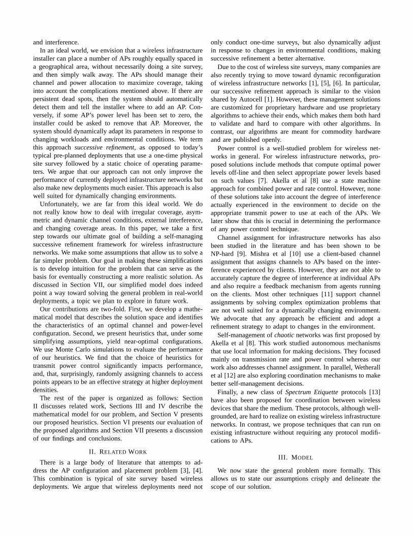
Fig. 1. Model Lattice that represents (x,y) location coordinates in the verticalplane and channels in the horizontal plane.
• APs in 2-D plane: We assume APs are located in a two-dimensional plane.
• Omni-directional Antennas: We assume all APs areequipped with omni-directional antennas.
• Physical Interference Model: We use the interferencemodel used in [14] for modeling signal path loss inour model. Using this model and the assumptions listedabove, our coverage areas can be represented as circulardisks in a 2-dimensional plane.
• Centralized solution: We assume that a single centralcoordinator determines the optimal solution. Given thatmost real deployments have a centralized controller forauthentication, authorization, and accounting (AAA), thisassumption is not particularly strong.
• Cooperation: We assume that the APs are cooperative.• Access Point Interference: We only consider AP-AP in-
terference for our model.• Symmetric channels: We assume channels are symmetric.• Identical APs: We assume all APs have identical discrete
power levels and choice of channels.
Based on these assumptions, we can geometrically representour model as shown in Fig. 1. The vertical plane on the latticeembeds the locations of each of the access points, which arefixed. The channels are represented by the third dimensionas the horizontal plane on the lattice. The transmit powerand corresponding coverage areas of each of the APs arerepresented by dashed circles around the origins A, B, andC. Larger transmit powers correspond to larger circles on the2-D plane. Therefore, using this model, overlapping circlesindicate interference between neighbouring APs.
With this model and the stated assumptions, we translatethe CAPC optimization problem to two simple geometricproblems:
1) Packing variable-size disks on a rectangle (PACK-RECT): Here, we model the utility function as follows:
• U(x, y) = 0 if there is no coverage at(x, y) i.e.AP (x, y) = φ
• U(x, y) = 1 if Interfere(x, y) = φ• U(x, y) = −∞ if Interfere(x, y) 6= φ
Here, we study power-control only (i.e. a single chan-nel), ignoring the effects of client load and assuminguniform signal strength in a coverage area. Given theutility function above, it is easy to see that no coverageoverlap between adjacent APs is allowed. The problemthus reduces to a packing problem forfixed-locationvariable-sized disks on a 2-dimensional plane wherethe objective is to maximize the coverage of the plane.This problem is computationally hard because there arepn possible solutions wheren is the number of accesspoints andp is the number of discrete power levels foreach AP. For even small deployments with 10 APs andconsidering only 5 possible power levels, there are morethan 9 million possible solutions.
2) Packing variable-size disks on a stack of rectangles(PACK-ST): This problem extends the previous one formultiple channels, keeping the utility function the same.In this case, each rectangle represents a separate channel.Due to the additional degree of freedom, we now needto solve the channel assignment problem as well. It hasbeen shown in [9] that the channel assignment problemfor Wireless LANs is NP-hard3.
Optimal solutions to even these simplified problems arecomputationally hard. Therefore, in an effort to build practicalsolutions, we devise heuristics to approximate the optimalsolution. We then compare their performance relative to theoptimal solution, computed using exhaustive search.
V. HEURISTICS
We now present three heuristic power-control algorithmsfor the PACK-RECT problem and two algorithms for jointchannel assignment and power control (PACK-ST). All APsare initialized to the lowest power level (i.e. transmit powerof zero) when the algorithms begin execution.
A. Randomized Incremental Algorithm (RIA)
The idea behind this algorithm is to pick an AP at randomand increase its power level, until either the maximum poweris reached, or the AP begins to interfere with another AP. Moreformally, the algorithm first places all APs into an unorderedfeasibleset. It then randomly picks an AP from the set andincreases its power level by one step. If the transmit power ofthe AP cannot be increased any further or increasing its powercauses interference, it is removed from the set, otherwise itis kept. The algorithm then selects another AP at random andrepeats this process until eventually all APs have been removedfrom the set. This process is illustrated in Algorithm 1.
Due to randomization, a single run of this algorithm doesnot always yield a good solution. Therefore we run thealgorithm many times and choose the run with the bestperformance. In the worst case, no APs interfere and thealgorithm incrementally increases the power of each AP untilall APs reach maximum transmit power. Therefore, the running
3The authors reduce the channel assignment problem to a maximumk-colorable graph problem on an unweighted graph, wherek is the number ofchannels.
Algorithm 1 Randomized Incremental Algorithm(Tx = TransmitPower)
1: Place all APs into feasible setf .2: Randomly select an access pointAPi from f .3: if AP ′
is Tx 6= max. Tx then4: IncreaseAPi’s power by one.5: if ( ∃(x, y) s.t. U(x, y) = −∞ ) then6: DecreaseAPi’s power by one and allocate it this
power level.7: RemoveAPi from f .8: end if9: else
10: RemoveAPi from f and allocate it its current powerlevel.
11: end if12: if f = ∅ then13: Terminate.14: else15: Go to step 2.16: end if
Algorithm 2 Generalized Greedy Power Allocation Algorithm(Tx = Transmit Power)
1: Place all APs in a setf2: Order the set according to the power control algorithm
being used.3: Remove the first AP,APi from f .4: Expand coverage ofAPi until (∃(x, y) s.t. U(x, y) =−∞) or APi’s Tx = max. Tx.
5: if ( ∃(x, y) s.t. U(x, y) = −∞ ) then6: DecreaseAPi’s power by one and allocate it this power
level.7: end if8: if f = ∅ then9: Terminate.
10: else11: Go to step 3.12: end if
time of RIA is bounded byO(p ∗ n), wherep andn are thenumber of discrete power levels and access points respectively.
B. Generalized Greedy Power Allocation Algorithm
Algorithm 2 illustrates the general steps followed by theother two power control algorithms. The generalized algorithmgreedily increases the transmit power of an AP, chosen in turnfrom an ordered feasible set, to the maximum possible power,given AP interference and power constraints.
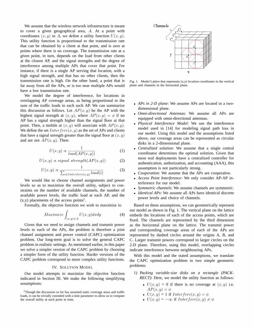
1) Distance-based Ordering Algorithm (DOA):The DOAalgorithm orders the feasible set by decreasing distance ofan AP from the center of mass (or centroid) defined by: (∑
i(xi/n),∑
i(yi/n) ), where (xi, yi) are the coordinatesof APi and n is the number of APs. The DOA algorithm isbased on the idea that APs farthest from the center of massare likely to experience less interference and thus should
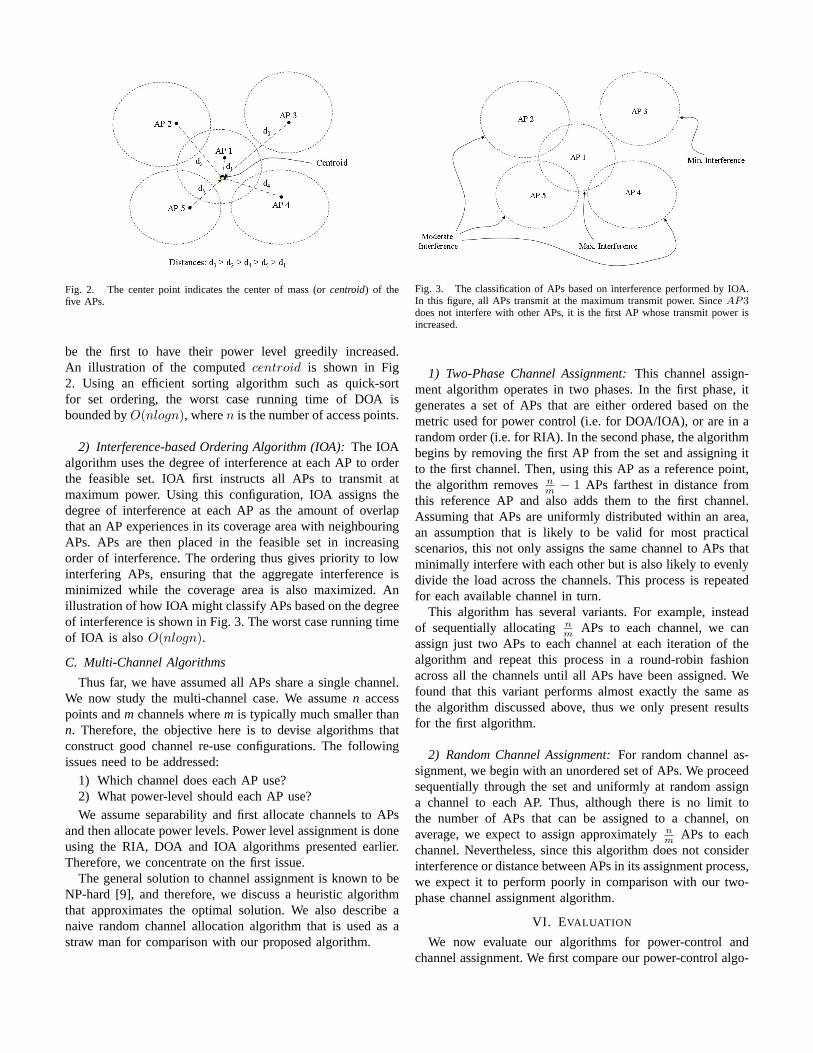
Fig. 2. The center point indicates the center of mass (orcentroid) of thefive APs.
be the first to have their power level greedily increased.An illustration of the computedcentroid is shown in Fig2. Using an efficient sorting algorithm such as quick-sortfor set ordering, the worst case running time of DOA isbounded byO(nlogn), wheren is the number of access points.
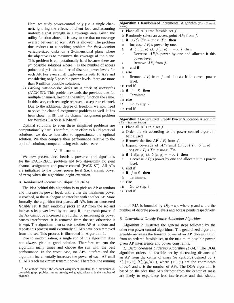
2) Interference-based Ordering Algorithm (IOA):The IOAalgorithm uses the degree of interference at each AP to orderthe feasible set. IOA first instructs all APs to transmit atmaximum power. Using this configuration, IOA assigns thedegree of interference at each AP as the amount of overlapthat an AP experiences in its coverage area with neighbouringAPs. APs are then placed in the feasible set in increasingorder of interference. The ordering thus gives priority to lowinterfering APs, ensuring that the aggregate interference isminimized while the coverage area is also maximized. Anillustration of how IOA might classify APs based on the degreeof interference is shown in Fig. 3. The worst case running timeof IOA is alsoO(nlogn).
C. Multi-Channel Algorithms
Thus far, we have assumed all APs share a single channel.We now study the multi-channel case. We assumen accesspoints andm channels wherem is typically much smaller thann. Therefore, the objective here is to devise algorithms thatconstruct good channel re-use configurations. The followingissues need to be addressed:
1) Which channel does each AP use?2) What power-level should each AP use?We assume separability and first allocate channels to APs
and then allocate power levels. Power level assignment is doneusing the RIA, DOA and IOA algorithms presented earlier.Therefore, we concentrate on the first issue.
The general solution to channel assignment is known to beNP-hard [9], and therefore, we discuss a heuristic algorithmthat approximates the optimal solution. We also describe anaive random channel allocation algorithm that is used as astraw man for comparison with our proposed algorithm.
Fig. 3. The classification of APs based on interference performed by IOA.In this figure, all APs transmit at the maximum transmit power. SinceAP3does not interfere with other APs, it is the first AP whose transmit power isincreased.
1) Two-Phase Channel Assignment:This channel assign-ment algorithm operates in two phases. In the first phase, itgenerates a set of APs that are either ordered based on themetric used for power control (i.e. for DOA/IOA), or are in arandom order (i.e. for RIA). In the second phase, the algorithmbegins by removing the first AP from the set and assigning itto the first channel. Then, using this AP as a reference point,the algorithm removesnm − 1 APs farthest in distance fromthis reference AP and also adds them to the first channel.Assuming that APs are uniformly distributed within an area,an assumption that is likely to be valid for most practicalscenarios, this not only assigns the same channel to APs thatminimally interfere with each other but is also likely to evenlydivide the load across the channels. This process is repeatedfor each available channel in turn.
This algorithm has several variants. For example, insteadof sequentially allocatingn
m APs to each channel, we canassign just two APs to each channel at each iteration of thealgorithm and repeat this process in a round-robin fashionacross all the channels until all APs have been assigned. Wefound that this variant performs almost exactly the same asthe algorithm discussed above, thus we only present resultsfor the first algorithm.
2) Random Channel Assignment:For random channel as-signment, we begin with an unordered set of APs. We proceedsequentially through the set and uniformly at random assigna channel to each AP. Thus, although there is no limit tothe number of APs that can be assigned to a channel, onaverage, we expect to assign approximatelyn
m APs to eachchannel. Nevertheless, since this algorithm does not considerinterference or distance between APs in its assignment process,we expect it to perform poorly in comparison with our two-phase channel assignment algorithm.
VI. EVALUATION
We now evaluate our algorithms for power-control andchannel assignment. We first compare our power-control algo-

rithms with each other and the optimal configuration. We thencompare the two-phase channel assignment algorithm withrandom channel assignment.
A. Evaluation Methodology
We have written a compact simulator in Java to compareour algorithms. We emulate a random deployment scenario byrandomly placing APs on a two-dimensional grid of fixed size(i.e. 500x500). APs are placed such that no two APs occupythe same location but however may be within interferencerange of one another (even if they transmit at minimumpower). This may cause some APs to be effectively blockedout during the configuration generation process. We discussthe implications of this problem in later sections. The inputsto the simulation include:
• The number of deployed APs.• The number of available channels.• The number of transmit powers to choose from.• The maximum transmit power of all APs.• The power control algorithm being used.• The channel assignment algorithm being used.Coverage areas of APs are represented as uniform circular
areas on the grid. As indicated in section IV, since weare solving the PACK-RECT and PACK-ST problems, theobjective here is to maximize coverage of the grid whilekeeping the interference zero. The maximum transmit powerof an AP is computed by taking the maximum coverage ofthe AP as a fraction of the total grid area (which is 30%for our simulations). This prevents any single AP from usingup the entire grid, since, due to power limitations, this isunlikely to happen in practice. For most of our results, wehave also fixed the number of transmit power levels to15.The number of transmit power levels are quite diverse acrossdifferent vendors [15][2] and we find that15 power levelscovers the space of most typical radios. For our multi-channelresults, we also fixed the number of available channels to three.This represents the most widely-deployed 802.11b systems4.For transmission rate, we adopt a conservative approach whereAPs always transmit at 1 Mbps uniformly across their entirecoverage area. We defer the study of dynamic rate-adaptationschemes based onpath lossto future work.
To compute the utility, we have used Monte-Carlo sampling.That is, we randomly select some sample points within thecoverage areas to estimate the cumulative coverage of all theAPs. We could have used an exact method for computingcoverage areas by first computing the coverage of each APand then subtracting from it any overlapping zones. However,exactly computing overlaps is a mathematically daunting task.Monte-Carlo sampling provides a quick, simple, and fairlyaccurate approximation of the coverage of the grid. In ourcomputations, we used different sample sizes and comparedthe relative error in the computed result. When comparing
4Our multi-channel results only present the benefits of using multiplechannels and their effect on power control. We defer a study of the effect ofvarying the number of available channels on the performance of the algorithmsto future work.
Fig. 4. The square represents the area on which the APs are placed. Eachshade represents a separate channel.
Fig. 5. Histogram of performance of power control algorithms againstoptimal configuration using single channel and five power levels.
sample sizes of 50,000 and 250,000 for example, we foundthat the error in the computed utility was less than±1.6%,which is acceptable. The area of the grid was 250,000.
B. Results
We repeated our simulation 30 times in order to minimizestatistical variation in our results. For every run, we generatea set of randomized AP locations to prevent placement biasesthat could affect any of our algorithms. For RIA, in each run,we also ran the algorithm 10 times on the same set of APlocations and took the maximum of the computed utilities. Anexample output of our simulator is shown in Fig. 4. We nowdiscuss our results further.
Fig. 5 presents the mean coverage area for each of ourpower-control algorithms and the optimal solution (using only

Fig. 6. Performance of power control algorithms using a single channel and15 power-levels
Fig. 7. Comparison of power control algorithms based on the number ofAPs used by the algorithms, using a single channel and 15 power-levels
a single channel and five power levels). For these low densitydeployments, we see that the IOA and DOA algorithms per-form quite close to the optimal solution, which was computedusing exhaustive search of all possible configurations. For highdensity deployments, we are not able to provide a quantitativecomparison since the search space for the optimal solutionincreases exponentially fast with increasing AP densities. Ingeneral, since we need to assign both power levels and chan-nels to APs, the size of the search space effectively becomesPN ∗CN , where P = number of transmit powers, C = numberof channels, and N is the number of APs. For P = 5, C = 3,and N = 10, we have≈ 576 billion possible configurations!However, as we discuss later, we do obtain evidence of near-optimal behavior even for high density deployments from ourmulti-channel results. These results show that our algorithmscover almost 100% of the grid, clearly indicating that ouralgorithms are near optimal.
Fig. 6 presents a comparison of IOA, DOA, and RIA. We
Fig. 8. Performance of power control algorithms using random channelassignment for 3 channels and 15 power-levels
Fig. 9. Performance of power control algorithms using two-phase channelassignment for 3 channels and 15 power-levels
observe that RIA always performs worse than IOA and DOA,especially in high density environments. This is probablybecause RIA does not bias power-level increases towardsAPs that are in less congested areas, causing it to performpoorly in high-density environments where opportunities forinterference increase. Another reason may be that RIA incre-ments power levels atall APs. In contrast, DOA and IOAgreedily maximize their coverage at each step of the algorithm.Consequently, with these algorithms, at high AP densities,APs that are close to an AP transmitting at high power mayeffectively be blocked from communicating at all. Althoughthis may be thought of as negative behavior, it is actuallybeneficial since it serves to reduce the overall interferencein the system. Figure 7 illustrates this by showing that thenumber of APs can be reduced by as much as 60% with theIOA algorithm while RIA uses almost all of the available APs.This result also gives us an intuition as to the optimal numberof APs that would be required to cover a grid of given size.
We now turn our attention to the multi-channel case. Fig. 8presents results for our power-control algorithms using randomchannel assignment and Fig. 9 shows the performance ofthe power control algorithms using our two-phase channelassignment algorithm. These figures demonstrate the bene-fits of using multiple channels over a single channel. Fordense environments, we see an almost 37% increase in thecumulative coverage area as compared to a single channel.Moreover, the percentage grid coverage of the IOA/DOAalgorithms increases to approximately 93%, from about 70%for the single channel case. Since the interference region iseffectively partitioned among the three channels, the coveragearea increases. In addition, we also observe that the gapbetween RIA and IOA/DOA has also decreased. Since theinterference per channel has been reduced, RIAs blindness tointerference does not hurt it as much.
When we compare the performance of the random channelassignment algorithm and our two-phase channel assignmentalgorithm, we see that both channel allocation algorithmsperform roughly similarly across the board. At low AP den-sities, the two-phase algorithm does perform better becauseit places APs farthest away from each other (i.e. with leastinterference), onto a common channel. This gain is maximizedfor the first channel, but decreases for later channels, so thatoverall, the gain from this strategy is not too great, especiallyat higher AP densities. Intuitively, having multiple channelssimply partitions the problem space into three. At high enoughdensity, this reduction in problem size does not reduce theoverall interference level, and a random channel assignmentworks just as well as a more complex channel allocationstrategy. In such situations, performance depends more onthe power-allocation algorithm than the channel allocationalgorithm, as illustrated by the better performance of IOA andDOA over RIA for both channel allocation schemes. This leadsus to advocate the (far simpler) random channel allocationstrategy as a pragmatic solution in real-world deployments.
VII. D ISCUSSION ANDCONCLUSIONS
Deploying a wireless infrastructure network requires us tobalance several conflicting requirements. In this paper, we havetaken the first step towards an ideal world, where an installercan quickly set up a network and simply walk away. Wepropose a successive-refinement approach to deployment. Weargue that this approach is better suited for real-world wirelessdeployments. We also present a mathematical and geometricmodel that crisply describes the solution space and identifiesthe characteristics of an optimal configuration. We design andevaluate heuristics that yield near-optimal configurations. Wefind that the choice of heuristics for transmit power control ofaccess points is a crucial factor in determining the quality ofthe solution. We also find that a random channel assignmentapproach is effective for assigning channels as the deploymentdensity increases.
We hasten to point out that our results are preliminarybecause they do not capture several aspects of the real-world problem. For example, our interference model is very
simplistic and does not capture irregularity in the coverage ofthe APs. This affects IOA since it relies on the underlyinggeometric model. Also, our utility function assigns the sameutility to each point on the covered grid. In reality, this utilityis dependent upon many factors: uplink/downlink channelconditions, transmission rate, traffic load, etc. Finally, althoughour algorithms do perform well in simulation, we still need totest them on a real testbed.
Nevertheless, our results do allow us to develop someintuition about the form of the final solution:
• Although finding the optimal configuration even for oursimple problem is hard, to our surprise, we find that sim-ple heuristics closely approach this optimal configuration.
• In general, careful power control appears to be moreimportant than careful channel allocation. This resultshould hold even in more general conditions.
• Surprisingly, both IOA and DOA perform almost iden-tically even though IOA more accurately models thedegree of interference and was thus expected to besuperior to DOA. We can explain this phenomenon froma computational geometric perspective. Note that eachAP’s coverage area roughly corresponds to its Voronoiregion [16], i.e. the region such that points in the regionare closer to this AP than any other AP. Clearly, we needto first allocate power levels to APs in larger Voronoiregions, that are likely to be closer to the boundaryarea. The DOA metric does well because it sorts APs inorder of their distance from the centroid, which, due itsgreedy nature, are assigned larger power levels and thuslarger coverage areas. In this sense, DOA approximatelyallocates power levels in order of decreasing size of theVoronoi regions. Incidently, DOA is also insensitive tothe underlying geometric model, making it suitable fornon-circular coverage areas as well.
• We also observe that a naive random channel assignmentis able to perform similarly to an interference-aware twophase channel assignment.
Based on these observations, we conjecture the following:For sufficiently dense deployments, an effective configurationstrategy would be to first perform a random assignment ofchannels to APs, and then use a greedy power allocationalgorithm that is the same as or similar in spirit to DOA. Sincechannel assignment is performed at random, coordination isonly needed for power allocation.
Our future work lies in two directions. On the theoreticalside, we intend to explore the use of computational geometry,in particular Voronoi diagrams, to study the general problem.We are also extending our model to allow overlapping cover-age areas, which is necessary to support seamless mobility. Fora start, this can be modeled simply by modifying the utilityfunction as follows:U(x, y) = −k ∗α if |Interfere(x, y)| =k, where α is a tuning parameter. In this case, we essen-tially associate a disutility, corresponding to the number ofoverlapping APsk, at each point where overlap is possible(of course, this ignores the load at these APs). Our next
step is to augment our model to incorporate other sourcesof interference such as Client-AP interference and Client-Client interference. Finally, we are considering algorithmsthat permit rapid reconfiguration in response to changes inthe environment. On the practical side, we are constructinga real test bed on which to investigate the performance ofour algorithms. We hope to use this experience both to refineour assumptions and to test our algorithms in a more realisticsetting.
REFERENCES
[1] “AutoCell Product Solutions”http://www.autocell.com/products/index.html
[2] “Cisco Aeronet Access Point Hardware Installation Guide (for 340 and350 Series)”,Cisco Systems Inc, 2004.
[3] P. Sangtae “Optimal Acess Point Selection and Channel Assignmentin IEEE 802.11 Networks”, Masters Thesis, Department of ComputerScience and Engineering, University of North Texas,December 2004.
[4] Y. Lee, K. Kim, and Y. Choi “Optimization of AP Placement and ChannelAssignment in Wireless LANs”,In workshop on Wireless Local Networks(WLN), IEEE LCN,November 2002.
[5] “Trapeze Networks Wireless LAN Mobility System”http://www.trapezenetworks.com/products/descriptions.asp
[6] “AccessOne/Network OWS”http://www.strixsystems.com/products/productsmain.asp
[7] D. Qiao, S. Choi, A. Jain and K. Shin “Adaptive Transmit Power Controlin IEEE 802.11a Wireless LANs”,In Proceedings of IEEE VehicularTechnology Conference (VTC), October 2003.
[8] A. Akella, G. Judd, S. Seshan, and P. Steenkiste, “Self-Management inChaotic Wireless Deployments”,In Proceedings of 11th InternationalConference on Mobile Computing and Networking (MobiCom),August2005.
[9] M. Halldorsson and J. Halpern and L. Li and V. Mirrokni, “On spectrumsharing games”,In Proceedings of the 23rd annual ACM symposium onPrinciples of distributed computing (PODC),July 2004.
[10] A. Mishra, S. Bannerjee, and W. Arbaugh, “Weighted Coloring basedChannel Assignment for WLANs”,In Mobile Computing and Commu-nications Review, July 2005.
[11] K. K. Leung and B. “J” Kim, “Frequency Assignment for IEEE 802.11Wireless Networks”, In Proceedings of IEEE Vehicular TechnologyConference (VTC),October 2003.
[12] D. Wetherall, “Managing Chaotic Wireless Networks”,Presented atMicrosoft Research (MSR) Summit on Self-Managing Networks,June2005.
[13] D. Raychaudhuri and X. Jing “A Spectrum Etiquette Protocol forEfficient Coordination of Radio Devices in Unlicensed Bands”,InProceedings of 14th Annual IEEE International Symposium on PersonalIndoor and Mobile Radio Communications (PIMRC), Beijing, China,Sept. 2003.
[14] P. Gupta and P. R. Kumar “The Capacity of Wireless Networks”,InIEEE Transactions on Information Theory, Vol. 46, No. 2, March 2000.
[15] “Linksys Support Forum”http://www.linksysinfo.org/
[16] M. DeBerg, O. Schwarzkopf, M. Van Kreveld and M. Overmars, “Com-putational Geometry: Algorithms and Applications (Second Edition)”Springer-Verlag New York,2000.