A Study on the Contraction Joint Element & Damage Constitutive Model for Concrete Arch Dams (2014) -...
11
Xu et al. / J Zhejiang Univ-Sci A (Appl Phys & Eng) 2014 15(3):208-218 208 A study on the contraction joint element and damage constitutive model for concrete arch dams * Qiang XU †1 , Jian-yun CHEN 1,2 , Jing LI 1 , Hong-yuan YUE 1 ( 1 School of Civil and Hydraulic Engineering, Dalian University of Technology, Dalian 116023, China) ( 2 State Key Laboratory of Coastal and Offshore Engineering, Dalian University of Technology, Dalian 116023, China) † E-mail: [email protected] Received July 15, 2013; Revision accepted Nov. 15, 2013; Crosschecked Feb. 12, 2014 Abstract: A new contraction joint element model for the interface in different meshes between the arch dam sections is con- structed. The study on the elastic-plastic damage constitutive model for concrete, which is applied to multi-axial stresses, is also taken. The models of the dam-foundation-reservoir system for Xingbiling and Jinping concrete arch dams, China are calculated using the proposed contraction joint elements and the elastic-plastic damage constitutive model to verify the proposed models. Results showed that the proposed contraction joint element model has a high precision in simulating the behavior of contraction joints and the elastic-plastic damage constitutive model has a high precision in simulating the behavior of the damage to the concrete. Key words: Contraction joint element, Damage, Concrete, Arch dam, Constitutive model doi:10.1631/jzus.A1300244 Document code: A CLC number: TV3 1 Introduction It is necessary to study concrete arch dams, which play an important role in current engineering. The studies on concrete arch dams mainly focus on two aspects, which are the joint element model and the constitutive model for concrete. Ahmadi et al. (2001) proposed a nonlinear contraction joint element model with coupled shear-tensile behavior to analyze a dam-reservoir system. Liu et al. (2002) made a study on the effects of radiation damping on the con- traction joint opening of arch dams. Azmi and Paultre (2002) constructed a nonlinear contraction joint el- ement to describe the partial joint opening and closing as well as tangential displacement of concrete dams under seismic load. Long et al. (2005) used the contraction joint element model to simulate the opening and closing behaviors of contraction joints in arch dams during an earthquake. Arabshahi and Lotfi (2009) used the contraction joint element model to simulate the nonlinear seismic responses of concrete lift joints, which were sliding and joint opening. Zhang et al. (2009) used the contraction joint element model to analyze the Dagangshan arch dam under construction in China. However, these studies mainly focused on the contraction joint elements in the con- dition in which the meshes of the interface between dam sections were the same. However, the outlet structures in the arch dam caused contraction in joint elements in the condition in which the meshes of the interface between dam sections were different. Damage factors were introduced in constitutive models, which were proposed by Løland (1980), Krajcinovic (1983), Mazars and Pijaudier-Cabot (1989), Aifantis (1999) and so on, to describe the behavior of damaged concrete. Based on above Journal of Zhejiang University-SCIENCE A (Applied Physics & Engineering) ISSN 1673-565X (Print); ISSN 1862-1775 (Online) www.zju.edu.cn/jzus; www.springerlink.com E-mail: [email protected] * Project supported by the National Natural Science Foundation of China (Nos. 51109029, 51178081, 51138001, and 51009020), and the State Key Development Program for Basic Research of China (No. 2013CB035905) © Zhejiang University and Springer-Verlag Berlin Heidelberg 2014
-
Upload
jhdiazr9002 -
Category
Documents
-
view
25 -
download
2
Transcript of A Study on the Contraction Joint Element & Damage Constitutive Model for Concrete Arch Dams (2014) -...
Xu et al. / J Zhejiang Univ-Sci A (Appl Phys & Eng) 2014 15(3):208-218
208
A study on the contraction joint element and damage constitutive
model for concrete arch dams*
Qiang XU†1, Jian-yun CHEN1,2, Jing LI1, Hong-yuan YUE1 (1School of Civil and Hydraulic Engineering, Dalian University of Technology, Dalian 116023, China)
(2State Key Laboratory of Coastal and Offshore Engineering, Dalian University of Technology, Dalian 116023, China) †E-mail: [email protected]
Received July 15, 2013; Revision accepted Nov. 15, 2013; Crosschecked Feb. 12, 2014
Abstract: A new contraction joint element model for the interface in different meshes between the arch dam sections is con-structed. The study on the elastic-plastic damage constitutive model for concrete, which is applied to multi-axial stresses, is also taken. The models of the dam-foundation-reservoir system for Xingbiling and Jinping concrete arch dams, China are calculated using the proposed contraction joint elements and the elastic-plastic damage constitutive model to verify the proposed models. Results showed that the proposed contraction joint element model has a high precision in simulating the behavior of contraction joints and the elastic-plastic damage constitutive model has a high precision in simulating the behavior of the damage to the concrete.
Key words: Contraction joint element, Damage, Concrete, Arch dam, Constitutive model doi:10.1631/jzus.A1300244 Document code: A CLC number: TV3
1 Introduction It is necessary to study concrete arch dams,
which play an important role in current engineering. The studies on concrete arch dams mainly focus on two aspects, which are the joint element model and the constitutive model for concrete. Ahmadi et al. (2001) proposed a nonlinear contraction joint element model with coupled shear-tensile behavior to analyze a dam-reservoir system. Liu et al. (2002) made a study on the effects of radiation damping on the con-traction joint opening of arch dams. Azmi and Paultre (2002) constructed a nonlinear contraction joint el-ement to describe the partial joint opening and closing as well as tangential displacement of concrete
dams under seismic load. Long et al. (2005) used the contraction joint element model to simulate the opening and closing behaviors of contraction joints in arch dams during an earthquake. Arabshahi and Lotfi (2009) used the contraction joint element model to simulate the nonlinear seismic responses of concrete lift joints, which were sliding and joint opening. Zhang et al. (2009) used the contraction joint element model to analyze the Dagangshan arch dam under construction in China. However, these studies mainly focused on the contraction joint elements in the con-dition in which the meshes of the interface between dam sections were the same. However, the outlet structures in the arch dam caused contraction in joint elements in the condition in which the meshes of the interface between dam sections were different. Damage factors were introduced in constitutive models, which were proposed by Løland (1980), Krajcinovic (1983), Mazars and Pijaudier-Cabot (1989), Aifantis (1999) and so on, to describe the behavior of damaged concrete. Based on above
Journal of Zhejiang University-SCIENCE A (Applied Physics & Engineering)
ISSN 1673-565X (Print); ISSN 1862-1775 (Online)
www.zju.edu.cn/jzus; www.springerlink.com
E-mail: [email protected]
* Project supported by the National Natural Science Foundation of China (Nos. 51109029, 51178081, 51138001, and 51009020), and the State Key Development Program for Basic Research of China (No. 2013CB035905) © Zhejiang University and Springer-Verlag Berlin Heidelberg 2014
Xu et al. / J Zhejiang Univ-Sci A (Appl Phys & Eng) 2014 15(3):208-218
209
theories, many studies were made. Kuna-Ciska and Skrzypek (2004) studied the anisotropic evolution of damage factors for elastic-brittle materials based on the theory of continuum damage mechanics (CDM) and the finite element method (FEM). Marfia et al. (2004) analyzed the change in damage factors for reinforced concrete in the process of compressive and tensile softening. Mirzabozorg and Ghaemian (2005) proposed a damage constitutive model to describe the behavior of concrete under static and dynamic loads. Lin and Hu (2005) analyzed the effects of the strain-rate on a damage constitutive model for con-crete. Calayir and Karaton (2005) used a continuum damage model to describe the response of the con-crete gravity dams under seismic load. Contrafatto and Cuomo (2006) introduced the plastic theory into the damage constitutive model to describe the be-havior of concrete. Pan et al. (2009) presented a damage constitutive model to analyze the damage of arch dams during strong earthquakes using a massless foundation model and viscous-spring boundary input model. Thus, the problems of simulating the damage and the behavior of contraction joints of an arch dam are important for actual projects.
In this paper, the elastic-plastic damage evolving model for concrete are studied and the contraction joint element model is constructed to describe the behavior of contraction joints in the condition in which the meshes of the interface be-tween dam sections are different. Then numerical examples for the Xingbiling and Jinping arch dams are performed.
2 Modeling of the contraction joint element for the interface in different meshes between the arch dam sections
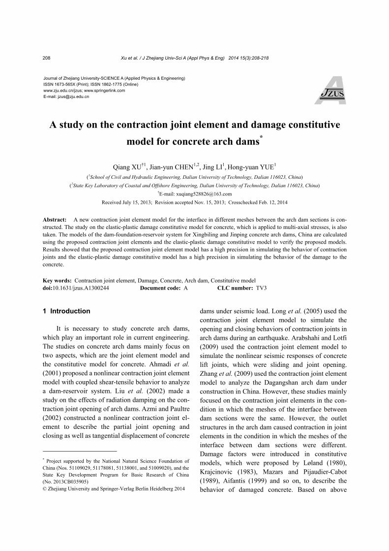
As shown in Fig. 1, the establishment of the joint
elements for the interface in different meshes between the arch dam sections can be divided into two steps. The main purpose of the first step is to establish the interface coordination method for the interface and arch dam section in different meshes. The main pur-pose of the second step is to establish the joint ele-ment models for the interface and the arch dam sec-tion in the same mesh.
2.1 Interface coordination method for the inter-face elements and the finite element of dam sec-tions in different meshes
The differences between the displacements of the interface and that of arch dam section in different meshes can be described as
21
1 2
1 2
1 2
1 2
1 2
2 21 1
11
1 1 2 2
1 1
1 1 2 2
1 1
,
nn
j ji iji
m mn n
i i j j m mi j
m mn n
i i j ji j
u u u
v v v
w w w
N uN u
N v N v
N w N w
N u
N v
N w
(1)
where
1 2
1 1 1 2 2 21 2 1 2[ , , , , , , , ],m n nN N N N N N N (2)
1 2
1 1 1 2 2 2 T1 2 1 2[ , , , , , , , ] ,m n nu u u u u u u (3)
1 2
1 1 1 2 2 2 T1 2 1 2[ , , , , , , , ] ,m n nv v v v v v v (4)
1 2
1 1 1 2 2 2 T1 2 1 2[ , , , , , , , ] ,m n nw w w w w w w (5)
where u1, v1, and w1 are the displacements in x, y, and z directions of the interface of the finite elements of dam sections shown in Fig. 2, respectively. u2, v2, and w2 are the displacements in x, y, and z directions of
interface elements shown in Fig. 2, respectively. 1,iu 1,iv and 1
iw are the displacements in x, y, and z
Fig. 1 Numerical method for the joints of arch dam sections in different meshes
X
Y
Z
Element in large scale
Interface element for dam joint
Finite element in small scale
P33
P43
P32
P4 2
P23
P1 3
P2 2
P1 2
P3 1P2
1P1
1
P4 1P5
1P6 1
P7 1
P8 1
P9 1
O
Xu et al. / J Zhejiang Univ-Sci A (Appl Phys & Eng) 2014 15(3):208-218
210
directions of node 1iP of the interface of the finite
elements of dam sections, respectively (the super-
script 2 denotes those for the interface elements); 1iN
and 2jN are the shape functions of the interface of the
finite elements of dam sections and the interface elements, respectively.
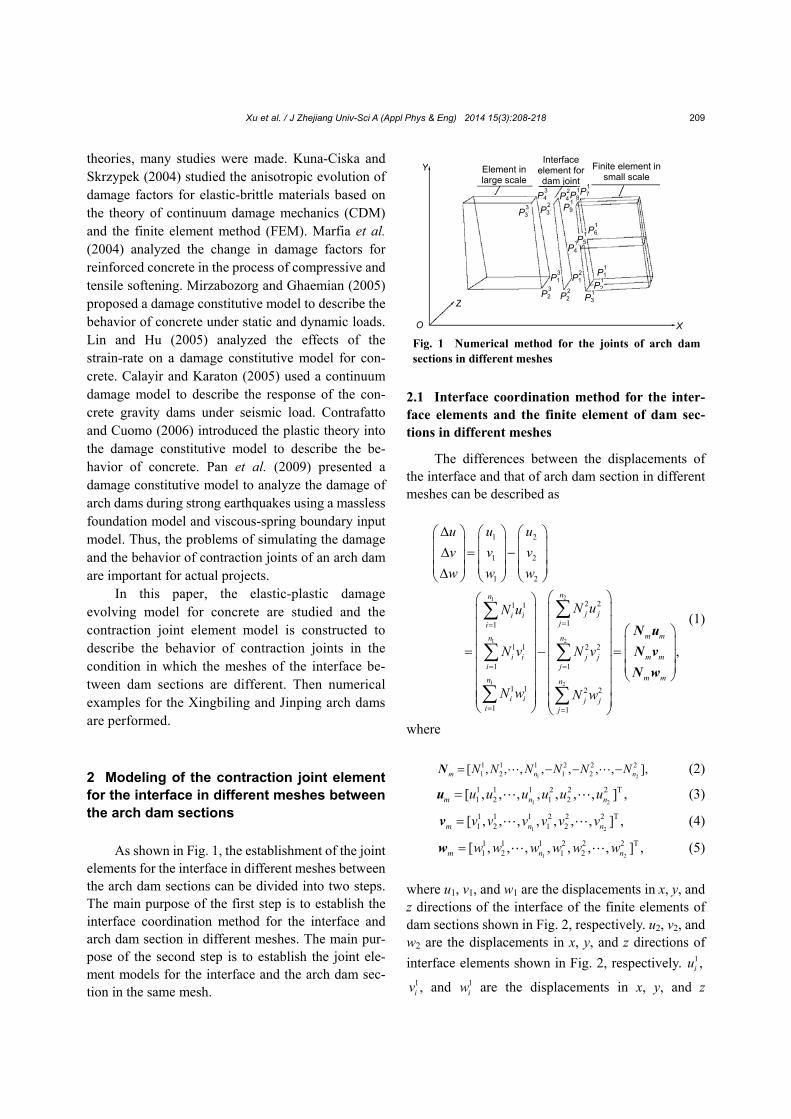
Thus, the virtual strain energy π of the interface between the interface of the finite elements of dam sections and interface elements can be expressed as
2 2 2
T
T
T T T T
T
T T T T
1 1 1π d
2 2 2
0 01
, , 0 0 [ , , ] d2
0 0
1, ,
2
0 0
0 0 [ , , ] d ,
0 0
x y zA
x
yA
z
m
m m m mA
m
x m
y m m m m
z m
k u k v k w A
k
u v w k u v w A
k
k
k A
k
N
u v w N
N
N
N u v w
N
0 0
0 0
0 0
0 0
0 0
0 0
(6)
where kx, ky, and kz are the virtual stiffness factors of the interface between the finite elements of dam sec-tions and the interface elements; A is the area of the interface between the finite element of dam sections and the interface element.
Based on the virtual work principle and using the variational method for Eq. (6), we can obtain:
T T T T
T
T T T T
T
T T T T
π ( , , )[ , , ]
( , , )
0 0
0 0 d [ , , ] ,
0 0
m m m x y z
m
m m m mA
m
x m
y m m m m
z m
k
k A
k
u v w F F F
N
u v w N
N
N
N u v w
N
0 0
0 0
0 0
0 0
0 0
0 0
(7)
where Fx, Fy, and Fz are the vectors of nodal force of the interface in x, y, and z directions, respectively.
The stiffness matrix of the interface between the finite elements of dam sections and the interface el-ements is
T
T
T
0 0
0 0
0 0
d .
m x
m yA
m z
m
m
m
k
k
k
A
N
K N
N
N
N
N
0 0
0 0
0 0
0 0
0 0
0 0
(8)
kx, ky, and kz are adopted as the value of the elastic modulus of concrete.
2.2 Joint element for the interface and finite ele-ments in the same mesh
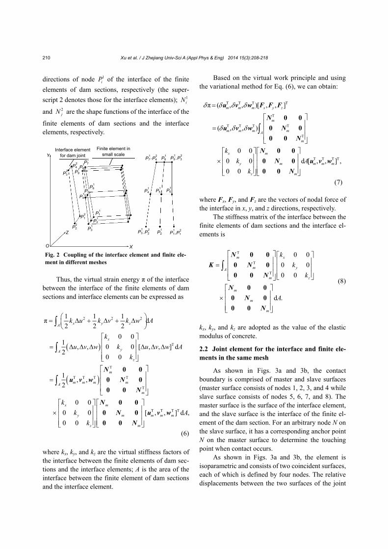
As shown in Figs. 3a and 3b, the contact boundary is comprised of master and slave surfaces (master surface consists of nodes 1, 2, 3, and 4 while slave surface consists of nodes 5, 6, 7, and 8). The master surface is the surface of the interface element, and the slave surface is the interface of the finite el-ement of the dam section. For an arbitrary node N on the slave surface, it has a corresponding anchor point N on the master surface to determine the touching point when contact occurs.
As shown in Figs. 3a and 3b, the element is isoparametric and consists of two coincident surfaces, each of which is defined by four nodes. The relative displacements between the two surfaces of the joint
Fig. 2 Coupling of the interface element and finite ele-ment in different meshes
Interface element for dam joint
Finite element in small scale
P7 1
P4 2
P81
P91
P32
P4 1
P51
P61
P3 1
P2 2
P21
P11
P12
P3 2
P4 2
P9 1P8
1P7
1
P5 1P6
1
P4 1
P2 1
P1 1
P3 1
P1 2
P2 2
X
Z
Y
O
Xu et al. / J Zhejiang Univ-Sci A (Appl Phys & Eng) 2014 15(3):208-218
211
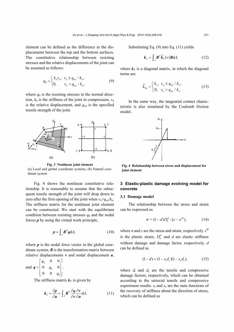
element can be defined as the difference in the dis-placements between the top and the bottom surfaces. The constitutive relationship between resisting stresses and the relative displacements of the joint can be assumed as follows:
n n n on n0
n on n
, / ,
0, / ,
k v v q kq
v q k
(9)
where q0 is the resisting stresses in the normal direc-tion, kn is the stiffness of the joint in compression, vn is the relative displacement, and qon is the specified tensile strength of the joint.
Fig. 4 shows the nonlinear constitutive rela-tionship. It is reasonable to assume that the subse-quent tensile strength of the joint will drop down to zero after the first opening of the joint when vn>qon/kn. The stiffness matrix for the nonlinear joint element can be constructed. We start with the equilibrium condition between resisting stresses q0 and the nodal forces p by using the virtual work principle,
T d ,
AA p B q (10)
where p is the nodal force vector in the global coor-dinate system, B is the transformation matrix between relative displacements v and nodal displacement u,
and 0
0
0
0 0
0 0 .
0 0
q
q
q
q
The stiffness matrix kT is given by
TT d .
AA
p q vk B
u v u (11)
Substituting Eq. (9) into Eq. (11) yields
TT T ( ) d ,
Av A k B k B (12)
where kT is a diagonal matrix, in which the diagonal terms are
n n on nTn
n on n
, / ,
0, / .
k v q kk
v q k
(13)
In the same way, the tangential contact charac-
teristic is also simulated by the Coulomb friction model.
3 Elastic-plastic damage evolving model for concrete
3.1 Damage model
The relationship between the stress and strain can be expressed as
el pl0= (1 ) : ( ),d D (14)
where σ and ε are the stress and strain, respectively. εpl
is the plastic strain, el0D and d are elastic stiffness
without damage and damage factor, respectively. d can be defined as
t c c t(1 ) (1 )(1 ),d s d s d (15)
where dt and dc are the tensile and compressive damage factors, respectively, which can be obtained according to the uniaxial tensile and compressive experiment results. st and sc are the state functions of the recovery of stiffness about the direction of stress, which can be defined as
Fig. 4 Relationship between stress and displacement for joint element
qn
qon
vn
kn
1
Fig. 3 Nonlinear joint element (a) Local and global coordinate systems; (b) Natural coor-dinate system
(a) (b)
Xu et al. / J Zhejiang Univ-Sci A (Appl Phys & Eng) 2014 15(3):208-218
212
t t t
c c c
ˆ1 ( ) , 0 1,
ˆ1 (1 ( )) , 0 1,
s w r w
s w r w
(16)
where ˆ1, if ( ) 0,ˆ( )ˆ0, if ( ) 0,
yr
y
(17)
where 3
1
ˆ ˆ( ) ,ii
y
(18)
where ̂ equals principal stresses. wt and wc are the tensile and compressive weight factors for the recovery of stiffness, respectively. wt and wc are relevant to the material properties, which control the recovery of
stiffness. ˆ( )r is the function for judging the tensile
and compressive statement under multi-axial stress, which is also the function of the principal stresses.
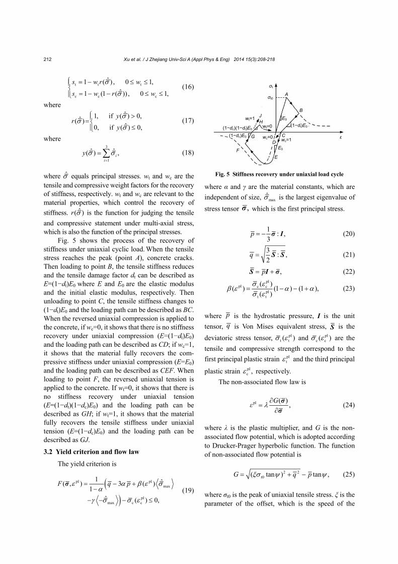
Fig. 5 shows the process of the recovery of stiffness under uniaxial cyclic load. When the tensile stress reaches the peak (point A), concrete cracks. Then loading to point B, the tensile stiffness reduces and the tensile damage factor dt can be described as E=(1−dt)E0 where E and E0 are the elastic modulus and the initial elastic modulus, respectively. Then unloading to point C, the tensile stiffness changes to (1−dt)E0 and the loading path can be described as BC. When the reversed uniaxial compression is applied to the concrete, if wc=0, it shows that there is no stiffness recovery under uniaxial compression (E=(1−dt)E0) and the loading path can be described as CD; if wc=1, it shows that the material fully recovers the com-pressive stiffness under uniaxial compression (E=E0) and the loading path can be described as CEF. When loading to point F, the reversed uniaxial tension is applied to the concrete. If wt=0, it shows that there is no stiffness recovery under uniaxial tension (E=(1−dt)(1−dc)E0) and the loading path can be described as GH; if wt=1, it shows that the material fully recovers the tensile stiffness under uniaxial tension (E=(1−dc)E0) and the loading path can be described as GJ.
3.2 Yield criterion and flow law
The yield criterion is
pl plmax
plmax c c
1 ˆ( , ) 3 ( )1
ˆ ( ) 0,
F q p
σ (19)
where α and γ are the material constants, which are
independent of size, max̂ is the largest eigenvalue of
stress tensor ,σ which is the first principal stress.
1
: ,3
p σ I (20)
3: ,
2q S S (21)
,p S I σ (22) pl
pl c cpl
t t
( )( ) (1 ) (1 ),
( )
(23)
where p is the hydrostatic pressure, I is the unit
tensor, q is Von Mises equivalent stress, S is the
deviatoric stress tensor, plt t( ) and pl
c c( ) are the
tensile and compressive strength correspond to the
first principal plastic strain plt and the third principal
plastic strain plc , respectively.
The non-associated flow law is
pl ( ),
Gε
σ
σ (24)
where λ is the plastic multiplier, and G is the non- associated flow potential, which is adopted according to Drucker-Prager hyperbolic function. The function of non-associated flow potential is
2 2t0( tan ) tan ,G q p (25)
where σt0 is the peak of uniaxial tensile stress. ξ is the parameter of the offset, which is the speed of the
σt
A
B
σt0
E0
(1−dt)E0
J
wt=1H
wt=0(1−dc)(1−dt)E0
(1−dc)E0 G wc=0wc=1 C
D
F
E
E0
ε
Fig. 5 Stiffness recovery under uniaxial load cycle

Xu et al. / J Zhejiang Univ-Sci A (Appl Phys & Eng) 2014 15(3):208-218
213
non-associated flow potential G that tends to asymp-tote (when ξ is closed to 0, the non-associated flow potential G is closed to a straight line). ψ is the dila-tancy angle in p-q plan. 4 Numerical examples and results
4.1 Verification for the proposed contraction joint element model
The Xingbiling arch dam in Guizhou province border between Guizhou and Yunnan provinces of China, which is 135.50 m in height and 444.86 m in the arc length of the dam crest under static and dy-namic load at the same time is used to verify the proposed contraction joint element model. The maximum thicknesses at crest and base of the dam are 8 m and 35 m, respectively. The total number of contraction joints in the dam is 2. The thickness of contraction joints is 2 cm. The dam is located in an extremely strong earthquake region with a designed peak ground acceleration (PGA) of 0.269g. The in-fluence using massless foundation is analysed. Fig. 6 shows the model of the Xingbiling arch dam. The dead depth of reservoir water is 105 m. The density of concrete is 2400 kg/m3. The elastic moduli of con-crete and rock are 22 GPa and 20 GPa, respectively. The Poisson’s ratios of concrete and rock are 0.167 and 0.24, respectively. The specified tensile strength qon and friction coefficient of the joints are 0 MPa and 0.6, respectively. Hydrodynamic pressure effects are considered using additional mass elements according to Westergaard expression for incompressible reser-voir fluid, in which the Westergaard additional masses are diagonal. Fig. 7 shows seismic ground accelera-tion histories.
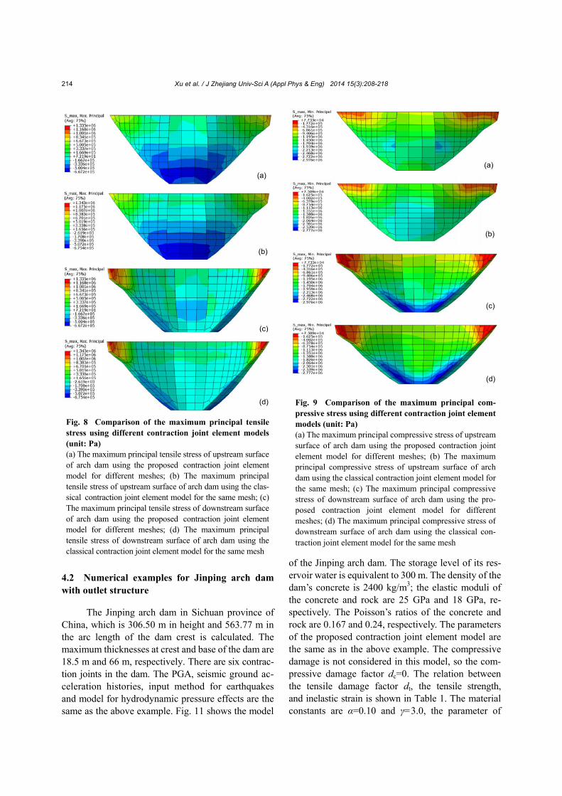
Figs. 8 and 9 show that the error of stress is approximately 6.5% between using the proposed contraction joint element model and the classical contraction joint element through comparing the maximum value of the stress. Therefore, the proposed joint element model has fewer errors in the distribu-tions of stress of the arch dam. Fig. 10 shows that the error of the maximum opening of the upstream face of the arch dam is approximately 1% between using the proposed contraction joint element model and the classical contraction joint element through comparing the maximum value of the opening. The error of the
maximum opening of the downstream face of the arch dam is approximately 6.5% between using the pro-posed contraction joint element model and the clas-sical contraction joint element. Therefore, the pro-posed joint element model has fewer errors in the opening of contraction joints of the arch dam, and the proposed joint element model has larger effects on the opening of contraction joints of the downstream face of the arch dam than that of the upstream face of the arch dam.
Fig. 6 Model of Xingbiling arch dam (a) Xingbiling arch dam with foundation; (b) Position of contraction joints
(b)
Contraction joints
(a)
Fig. 7 Seismic ground accelerations along (a) and across (b) the river, and in the vertical direction (c)
Xu et al. / J Zhejiang Univ-Sci A (Appl Phys & Eng) 2014 15(3):208-218
214
4.2 Numerical examples for Jinping arch dam with outlet structure
The Jinping arch dam in Sichuan province of China, which is 306.50 m in height and 563.77 m in the arc length of the dam crest is calculated. The maximum thicknesses at crest and base of the dam are 18.5 m and 66 m, respectively. There are six contrac-tion joints in the dam. The PGA, seismic ground ac-celeration histories, input method for earthquakes and model for hydrodynamic pressure effects are the same as the above example. Fig. 11 shows the model
of the Jinping arch dam. The storage level of its res-ervoir water is equivalent to 300 m. The density of the dam’s concrete is 2400 kg/m3; the elastic moduli of the concrete and rock are 25 GPa and 18 GPa, re-spectively. The Poisson’s ratios of the concrete and rock are 0.167 and 0.24, respectively. The parameters of the proposed contraction joint element model are the same as in the above example. The compressive damage is not considered in this model, so the com-pressive damage factor dc=0. The relation between the tensile damage factor dt, the tensile strength, and inelastic strain is shown in Table 1. The material constants are α=0.10 and γ=3.0, the parameter of
Fig. 8 Comparison of the maximum principal tensilestress using different contraction joint element models (unit: Pa) (a) The maximum principal tensile stress of upstream surfaceof arch dam using the proposed contraction joint elementmodel for different meshes; (b) The maximum principal tensile stress of upstream surface of arch dam using the clas-sical contraction joint element model for the same mesh; (c)The maximum principal tensile stress of downstream surface of arch dam using the proposed contraction joint element model for different meshes; (d) The maximum principal tensile stress of downstream surface of arch dam using the classical contraction joint element model for the same mesh
(a)
(b)
(c)
(d)
(a)
(b)
(c)
(d)
Fig. 9 Comparison of the maximum principal com-pressive stress using different contraction joint element models (unit: Pa) (a) The maximum principal compressive stress of upstreamsurface of arch dam using the proposed contraction joint element model for different meshes; (b) The maximum principal compressive stress of upstream surface of arch dam using the classical contraction joint element model for the same mesh; (c) The maximum principal compressive stress of downstream surface of arch dam using the pro-posed contraction joint element model for different meshes; (d) The maximum principal compressive stress ofdownstream surface of arch dam using the classical con-traction joint element model for the same mesh
Xu et al. / J Zhejiang Univ-Sci A (Appl Phys & Eng) 2014 15(3):208-218
215
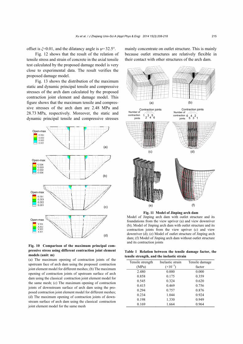
offset is ξ=0.01, and the dilatancy angle is ψ=32.5°. Fig. 12 shows that the result of the relation of
tensile stress and strain of concrete in the axial tensile test calculated by the proposed damage model is very close to experimental data. The result verifies the proposed damage model.
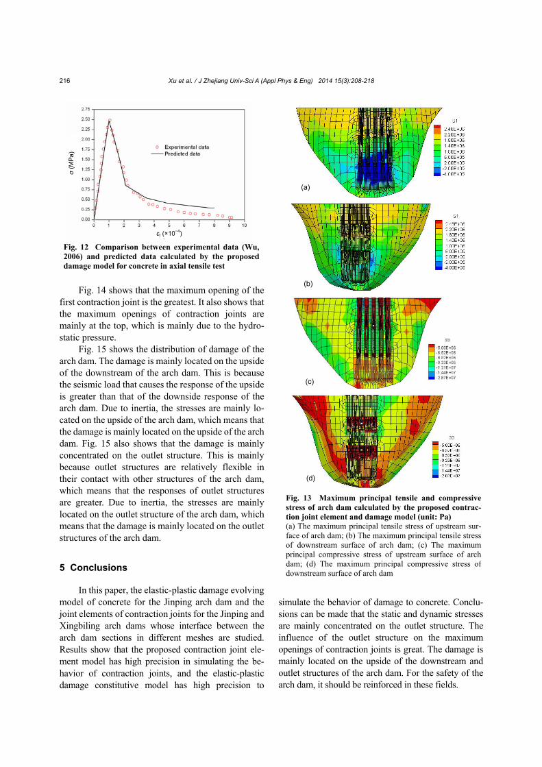
Fig. 13 shows the distribution of the maximum static and dynamic principal tensile and compressive stresses of the arch dam calculated by the proposed contraction joint element and damage model. This figure shows that the maximum tensile and compres-sive stresses of the arch dam are 2.48 MPa and 28.73 MPa, respectively. Moreover, the static and dynamic principal tensile and compressive stresses
mainly concentrate on outlet structure. This is mainly because outlet structures are relatively flexible in their contact with other structures of the arch dam.
Fig. 10 Comparison of the maximum principal com-pressive stress using different contraction joint element models (unit: m) (a) The maximum opening of contraction joints of the upstream face of arch dam using the proposed contractionjoint element model for different meshes; (b) The maximum opening of contraction joints of upstream surface of arch dam using the classical contraction joint element model for the same mesh; (c) The maximum opening of contraction joints of downstream surface of arch dam using the pro-posed contraction joint element model for different meshes; (d) The maximum opening of contraction joints of down-stream surface of arch dam using the classical contraction joint element model for the same mesh
(a)
Open-max
(b)
Open-max
(c)
Open-max
(d)
Open-max
Fig. 11 Model of Jinping arch dam Model of Jinping arch dam with outlet structure and its foundations from the view upriver (a) and view downriver(b); Model of Jinping arch dam with outlet structure and its contraction joints from the view upriver (c) and view downriver (d); (e) Model of outlet structure of Jinping arch dam; (f) Model of Jinping arch dam without outlet structureand its contraction joints
(a) (b)
(e) (f)
(c)
Contraction jointsNumber of contraction
joints1
23
45
6
(d)
Contraction joints
6 5
4 3
2 1
Number of contraction
joints
Table 1 Relation between the tensile damage factor, the tensile strength, and the inelastic strain
Tensile strength (MPa)
Inelastic strain (×10−3)
Tensile damage factor
2.480 0.000 0.000 0.858 0.175 0.359 0.545 0.324 0.620 0.415 0.469 0.756 0.294 0.757 0.876 0.234 1.044 0.924 0.198 1.330 0.949 0.169 1.664 0.964
Xu et al. / J Zhejiang Univ-Sci A (Appl Phys & Eng) 2014 15(3):208-218
216
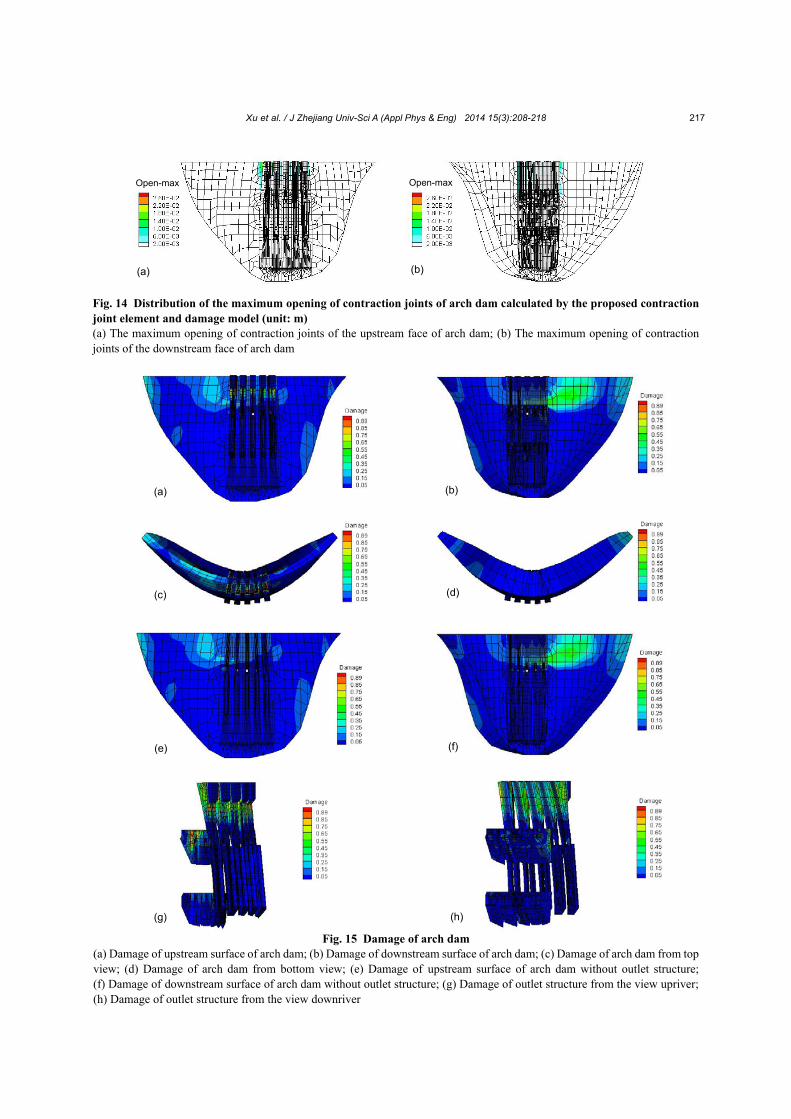
Fig. 14 shows that the maximum opening of the
first contraction joint is the greatest. It also shows that the maximum openings of contraction joints are mainly at the top, which is mainly due to the hydro-static pressure.
Fig. 15 shows the distribution of damage of the arch dam. The damage is mainly located on the upside of the downstream of the arch dam. This is because the seismic load that causes the response of the upside is greater than that of the downside response of the arch dam. Due to inertia, the stresses are mainly lo-cated on the upside of the arch dam, which means that the damage is mainly located on the upside of the arch dam. Fig. 15 also shows that the damage is mainly concentrated on the outlet structure. This is mainly because outlet structures are relatively flexible in their contact with other structures of the arch dam, which means that the responses of outlet structures are greater. Due to inertia, the stresses are mainly located on the outlet structure of the arch dam, which means that the damage is mainly located on the outlet structures of the arch dam.
5 Conclusions
In this paper, the elastic-plastic damage evolving model of concrete for the Jinping arch dam and the joint elements of contraction joints for the Jinping and Xingbiling arch dams whose interface between the arch dam sections in different meshes are studied. Results show that the proposed contraction joint ele-ment model has high precision in simulating the be-havior of contraction joints, and the elastic-plastic damage constitutive model has high precision to
simulate the behavior of damage to concrete. Conclu-sions can be made that the static and dynamic stresses are mainly concentrated on the outlet structure. The influence of the outlet structure on the maximum openings of contraction joints is great. The damage is mainly located on the upside of the downstream and outlet structures of the arch dam. For the safety of the arch dam, it should be reinforced in these fields.
σ (
MP
a)
εt (×10−4)
Fig. 12 Comparison between experimental data (Wu,2006) and predicted data calculated by the proposed damage model for concrete in axial tensile test
(a)
(b)
(c)
(d)
Fig. 13 Maximum principal tensile and compressive stress of arch dam calculated by the proposed contrac-tion joint element and damage model (unit: Pa) (a) The maximum principal tensile stress of upstream sur-face of arch dam; (b) The maximum principal tensile stress of downstream surface of arch dam; (c) The maximum principal compressive stress of upstream surface of arch dam; (d) The maximum principal compressive stress ofdownstream surface of arch dam
Xu et al. / J Zhejiang Univ-Sci A (Appl Phys & Eng) 2014 15(3):208-218
217
(a)
Open-max
(b)
Open-max
Fig. 14 Distribution of the maximum opening of contraction joints of arch dam calculated by the proposed contraction joint element and damage model (unit: m) (a) The maximum opening of contraction joints of the upstream face of arch dam; (b) The maximum opening of contraction joints of the downstream face of arch dam
(a) (b)
(c) (d)
(e) (f)
(g) (h)
Fig. 15 Damage of arch dam(a) Damage of upstream surface of arch dam; (b) Damage of downstream surface of arch dam; (c) Damage of arch dam from top view; (d) Damage of arch dam from bottom view; (e) Damage of upstream surface of arch dam without outlet structure; (f) Damage of downstream surface of arch dam without outlet structure; (g) Damage of outlet structure from the view upriver; (h) Damage of outlet structure from the view downriver
Xu et al. / J Zhejiang Univ-Sci A (Appl Phys & Eng) 2014 15(3):208-218
218
References Ahmadi, M.T., Izadinia, M., Bachmann, H., 2001. A discrete
crack joint model for nonlinear dynamic analysis of con-crete arch dam. Computers & Structures, 79(4):403-420. [doi:10.1016/S0045-7949(00)00148-6]
Aifantis, E.C., 1999. Strain gradient interpretation of size effects. International Journal of Fracture, 95(1-4): 299-314. [doi:10.1023/A:1018625006804]
Arabshahi, H., Lotfi, V., 2009. Nonlinear dynamic analysis of arch dams with joint sliding mechanism. Engineering Computations, 26(5):464-482. [doi:10.1108/026444009 10970158]
Azmi, M., Paultre, P., 2002. Three-dimensional analysis of concrete dams including contraction joint non-linearity. Engineering Structures, 24(6):757-771. [doi:10.1016/ S0141-0296(02)00005-6]
Calayir, Y., Karaton, M., 2005. A continuum damage concrete model for earthquake analysis of concrete gravity dam- reservoir systems. Soil Dynamics and Earthquake Engi-neering, 25(11):857-869. [doi:10.1016/j.soildyn.2005.05. 003]
Contrafatto, L., Cuomo, M., 2006. A framework of elastic- plastic damaging model for concrete under multiaxial stress states. International Journal of Plasticity, 22(12): 2272-2300. [doi:10.1016/j.ijplas.2006.03.011]
Krajcinovic, D., 1983. Constitutive equations for damaging materials. Journal of Applied Mechanics, 50(2):355-360. [doi:10.1115/1.3167044]
Kuna-Ciska, H., Skrzypek, J.J., 2004. CDM based modelling of damage and fracture mechanisms in concrete under tension and compression. Engineering Fracture Me-chanics, 71(4-6):681-698. [doi:10.1016/S0013-7944(03) 00023-7]
Lin, G., Hu, Z.Q., 2005. Earthquake safety assessment of concrete arch and gravity dams. Earthquake Engineering and Engineering Vibration, 4(2):251-264. [doi:10.1007/ s11803-005-0008-9]
Liu, X.J., Xu, Y.J., Wang, G.L., et al., 2002. Seismic response of arch dams considering infinite radiation damping and joint opening effects. Earthquake Engineering and En-gineering Vibration, 1(1):65-73. [doi:10.1007/s11803- 002-0009-x]
Long, Y.C., Zhou, Y.D., Zhang, C.H., 2005. A comparison study of nonlinear dynamic responses of arch dams based on two types of contraction joint models. Journal of Hy-draulic Engineering, 36(9):1094-1099 (in Chinese).
Løland, K.E., 1980. Continuous damage model for load- response estimation of concrete. Cement and Concrete Research, 10(3):395-402. [doi:10.1016/0008-8846(80) 90115-5]
Marfia, S., Rinaldi, Z., Sacco, E., 2004. Softening behavior of reinforced concrete beams under cyclic loading. Interna-tional Journal of Solids and Structures, 41(11-12): 3293-3316. [doi:10.1016/j.ijsolstr.2003.12.015]
Mazars, J., Pijaudier-Cabot, G., 1989. Continuum damage theory—application to concrete. Journal of Engineering Mechanics, 115(2):345-365. [doi:10.1061/(ASCE)0733- 9399(1989)115:2(345)]
Mirzabozorg, H., Ghaemian, M., 2005. Non-linear behavior of mass concrete in three-dimensional problems using a smeared crack approach. Earthquake Engineering and Structural Dynamics, 34(3):247-269. [doi:10.1002/eqe.423]
Pan, J.W., Zhang, C.H., Wang, J.T., et al., 2009. Seismic damage-cracking analysis of arch dams using different earthquake input mechanisms. Science in China Series E: Technological Sciences, 52(2):518-529. [doi:10.1007/ s11431-008-0303-6]
Wu, F., 2006. Experimental Study on Whole Stress-strain Curves of Concrete under Axial Tension. MS Thesis, Hunan University, China (in Chinese).
Zhang, C.H., Pan, J.W., Wang, J.T., 2009. Influence of seismic input mechanisms and radiation damping on arch dam response. Soil Dynamics and Earthquake Engineering, 29(9):1282-1293. [doi:10.1016/j.soildyn.2009.03.003]
中文概要:
本文题目:混凝土拱坝横缝单元和损伤本构的研究 A study on the contraction joint element and damage constitutive model for concrete arch dams
研究目的:研究混凝土拱坝多尺度横缝单元和坝体损伤。
创新要点:解决了拱坝坝段单元采用不同剖分形式(即多尺度剖分形式)时,在静动力荷载下,拱坝横
缝开度和坝体损伤的计算。 研究方法:首先建立大尺度交接面单元和小尺度单元坝段自由度耦合,然后建立大尺度交接面单元和大
尺度单元坝段横缝单元模型,并对坝体损伤本构的计算进行研究。 重要结论:通过对比计算发现,通过混凝土的损伤本构计算的应力峰值和实验结果相同,下降段的应力
应变曲线基本吻合。提出的不同尺度横缝单元模型对坝体应力和横缝开度的计算误差在 7%以
内。 关键词组:多尺度;横缝单元;损伤本构;拱坝;本构模型