A study on the behavior of beam-column connections in ... · In both connections, the steel area...
13
Volume 5, Number 5 (December 2012) p. 848-873 • ISSN 1983-4195 © 2012 IBRACON Due to the large increase in the use of precast concrete structures in multistory buildings, this work covers a study on the behavior of beam-column connection with emphasis on the continuity provided by the slab reinforcement. Two prototypes were tested, each one with a different detail of the continuity reinforcement distribution. In both connections, the steel area used on the concrete cover of the hollow core slab was the same, varying the amount of bars that passed through the column and the ones that were placed adjacent to the column. The experimental results showed that the connection with bars adjacent to the column presented stiffness increase and a better cracking control. According to the classification the two tested connections can be considered semi-rigid. Keywords: precast concrete, semi-rigid connection, beam-column connection. Em decorrência do grande aumento na utilização de estruturas pré-moldadas de concreto na construção de edifícios de múltiplos pavimentos, abordou-se neste trabalho o estudo do comportamento de ligações viga-pilar com ênfase na continuidade proporcionada pela armadura da laje. Dois protótipos foram ensaiados, cada um deles com um detalhamento diferente de distribuição da armadura de continuidade. Em ambas as ligações, a área de aço utilizada na capa da laje foi a mesma, variando a quantidade de barras que passavam através do pilar por meio de aber- turas e as que se localizavam em suas laterais. Os resultados experimentais mostraram que a ligação com barras laterais ao pilar apresentaram aumento da rigidez e maior controle da fissuração. De acordo com a classificação realizada, as duas ligações ensaiadas podem ser consideradas semi-rígidas. Palavras-chave: concreto pré-moldado, ligação semi-rígida, ligação viga-pilar. A study on the behavior of beam-column connections in precast concrete structures: experimental analysis Estudo do comportamento de ligações viga-pilar em estruturas pré-moldadas de concreto: análise experimental M. N. KATAOKA a [email protected] M. A. FERREIRA b [email protected] A. L. H. C. EL DEBS c [email protected] a Department of Structural Engineering, School of Engineering of São Carlos, University São Paulo, [email protected], Trabalhador Saocarlense Avenue, nº 400, CEP: 13566-580, São Carlos, SP, Brazil. b Department of Civil Engineering, Federal University of São Carlos, [email protected], Via Washington Luís, km 235, CEP: 13565-905, São Carlos, Brasil. c Department of Structural Engineering, School of Engineering of São Carlos, University São Paulo, [email protected], Trabalhador Saocarlense Avenue, nº 400, CEP: 13566-580, São Carlos, SP, Brazil. Received: 21 Aug 2012 • Accepted: 01 Oct 2012 • Available Online: 05 Dec 2012 Abstract Resumo
Transcript of A study on the behavior of beam-column connections in ... · In both connections, the steel area...
Volume 5, Number 5 (December 2012) p. 848-873 • ISSN 1983-4195
© 2012 IBRACON
Due to the large increase in the use of precast concrete structures in multistory buildings, this work covers a study on the behavior of beam-column connection with emphasis on the continuity provided by the slab reinforcement. Two prototypes were tested, each one with a different detail of the continuity reinforcement distribution. In both connections, the steel area used on the concrete cover of the hollow core slab was the same, varying the amount of bars that passed through the column and the ones that were placed adjacent to the column. The experimental results showed that the connection with bars adjacent to the column presented stiffness increase and a better cracking control. According to the classification the two tested connections can be considered semi-rigid.
Keywords: precast concrete, semi-rigid connection, beam-column connection.
Em decorrência do grande aumento na utilização de estruturas pré-moldadas de concreto na construção de edifícios de múltiplos pavimentos, abordou-se neste trabalho o estudo do comportamento de ligações viga-pilar com ênfase na continuidade proporcionada pela armadura da laje. Dois protótipos foram ensaiados, cada um deles com um detalhamento diferente de distribuição da armadura de continuidade. Em ambas as ligações, a área de aço utilizada na capa da laje foi a mesma, variando a quantidade de barras que passavam através do pilar por meio de aber-turas e as que se localizavam em suas laterais. Os resultados experimentais mostraram que a ligação com barras laterais ao pilar apresentaram aumento da rigidez e maior controle da fissuração. De acordo com a classificação realizada, as duas ligações ensaiadas podem ser consideradas semi-rígidas.
Palavras-chave: concreto pré-moldado, ligação semi-rígida, ligação viga-pilar.
A study on the behavior of beam-column connections in precast concrete structures: experimental analysis
Estudo do comportamento de ligações viga-pilar em estruturas pré-moldadas de concreto: análise experimental
M. N. KATAOKA a
M. A. FERREIRA b
A. L. H. C. EL DEBS c
a Department of Structural Engineering, School of Engineering of São Carlos, University São Paulo, [email protected], Trabalhador Saocarlense Avenue, nº 400, CEP: 13566-580, São Carlos, SP, Brazil.b Department of Civil Engineering, Federal University of São Carlos, [email protected], Via Washington Luís, km 235, CEP: 13565-905, São Carlos, Brasil.c Department of Structural Engineering, School of Engineering of São Carlos, University São Paulo, [email protected], Trabalhador Saocarlense Avenue, nº 400, CEP: 13566-580, São Carlos, SP, Brazil.
Received: 21 Aug 2012 • Accepted: 01 Oct 2012 • Available Online: 05 Dec 2012
Abstract
Resumo

1. Introduction
The researches about the behavior of precast concrete structures are very important for the modernization of the Civil Construction Industry, mainly to improve the quality, productivity and to promote the rationalization on sites.After the Second World War, the precast concrete structures were so much used to reconstruct the Europe. In this period, new meth-ods and constructions techniques that emphasize the rationaliza-tion and the productivity became necessary to boost the prefabrica-tion. The large-scale and the few available workers were the main reasons for the development of the precast concrete structures. The use of precast concrete structures is increasing in Brazil. The reason for this growth is the efficiency of this type of structure to meet the market requirements that are the compliance with dead-lines and technical quality. These requirements are important for buildings mainly which have large spans, for example, industrial buildings.The main difference between precast concrete structures and the traditional reinforced concrete structures is the presence of con-nections. Therefore, the study of the connections behavior stands out in the field of precast concrete structures. The connections be-havior has an important role because it is responsible for transmis-sion and redistribution of the stress. The ABNT NBR 9062 [1] is the Brazilian Code that governs the design and construction of precast concrete structures. This code has received many contributions from several studies involving the behavior of connections with the intention of spreading the technical knowledge obtained and usual the use of this type of structure.The connections are regions that have a complex behavior. In these regions occur stress concentrations and for this reason the connections deserve a special attention of the researchers and the designers. In general, the connections between precast ele-ments do not behave exactly as they are considered in the struc-tural analysis. The designers consider that the connections allow
or prevent entirely the relative displacements between the con-nected elements, which do not happen. What happens is that the connections have an intermediate behavior and must be called as semi-rigid. However, the development of this type of connection is extremely important to enable the use of precast concrete system in multistory buildings.
2. Analysis of semi-rigid connections
The connections have been defined as “semi-rigid” in the study of precast concrete structures since the 1980s. This term has been used since 1930 to designate connections in steel structures and now it is becoming common among researchers in the field of pre-fabricated structures.Several types of studies on precast concrete connections have been done in research centers around the world. In general, studies include the development of connections which provide high rigidity and easiness of implementation. In the research of Shariatmadar and Beydokhti [2] was tested a connection be-tween precast beam and column preformed without the use of corbel. The region which joins the elements was cast in situ. The improvement of the bending moment transfer to the col-umn by the use of prestressed reinforcement was another way found by the researchers to improve the connections behav-ior. Hawileh et al. [3] performed a numerical and experimental study of connections involving prestressed reinforcement. The authors compared both results and they concluded that com-puter simulation is an economical option to analyze the behavior of connections. Following this line of study, Kaya and Arslan [4] also analyzed beam-column connections with prestressed reinforcement. They noted that for different levels of prestress-ing applied, the connections presented satisfactory behavior. In the literature review was found that the use of prestressed re-inforcement in precast concrete connections has been studied for a long time. The search of Saqan [5] is one of these stud-
849IBRACON Structures and Materials Journal • 2012 • vol. 5 • nº 6
M. N. KATAOKA | M. A. FERREIRA | A. L. H. C. EL DEBS
Figure 1 – Indication the local of load application and the node of a porch structure analyzed
850 IBRACON Structures and Materials Journal • 2012 • vol. 5 • nº 6
A study on the behavior of beam-column connections in precast concrete structures: experimental analysis
3.1 Design of the connection
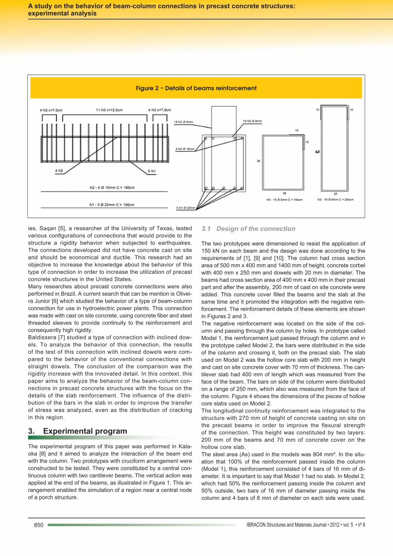
The two prototypes were dimensioned to resist the application of 150 kN on each beam and the design was done according to the requirements of [1], [9] and [10]. The column had cross section area of 500 mm x 400 mm and 1400 mm of height, concrete corbel with 400 mm x 250 mm and dowels with 20 mm in diameter. The beams had cross section area of 400 mm x 400 mm in their precast part and after the assembly, 200 mm of cast on site concrete were added. This concrete cover filled the beams and the slab at the same time and it promoted the integration with the negative rein-forcement. The reinforcement details of these elements are shown in Figures 2 and 3.The negative reinforcement was located on the side of the col-umn and passing through the column by holes. In prototype called Model 1, the reinforcement just passed through the column and in the prototype called Model 2, the bars were distributed in the side of the column and crossing it, both on the precast slab. The slab used on Model 2 was the hollow core slab with 200 mm in height and cast on site concrete cover with 70 mm of thickness. The can-tilever slab had 400 mm of length which was measured from the face of the beam. The bars on side of the column were distributed on a range of 250 mm, which also was measured from the face of the column. Figure 4 shows the dimensions of the pieces of hollow core slabs used on Model 2.The longitudinal continuity reinforcement was integrated to the structure with 270 mm of height of concrete casting on site on the precast beams in order to improve the flexural strength of the connection. This height was constituted by two layers: 200 mm of the beams and 70 mm of concrete cover on the hollow core slab. The steel area (As) used in the models was 804 mm². In the situ-ation that 100% of the reinforcement passed inside the column (Model 1), this reinforcement consisted of 4 bars of 16 mm of di-ameter. It is important to say that Model 1 had no slab. In Model 2, which had 50% the reinforcement passing inside the column and 50% outside, two bars of 16 mm of diameter passing inside the column and 4 bars of 8 mm of diameter on each side were used.
ies. Saqan [5], a researcher of the University of Texas, tested various configurations of connections that would provide to the structure a rigidity behavior when subjected to earthquakes. The connections developed did not have concrete cast on site and should be economical and ductile. This research had an objective to increase the knowledge about the behavior of this type of connection in order to increase the utilization of precast concrete structures in the United States.Many researches about precast concrete connections were also performed in Brazil. A current search that can be mention is Olivei-ra Junior [6] which studied the behavior of a type of beam-column connection for use in hydroelectric power plants. This connection was made with cast on site concrete, using concrete fiber and steel threaded sleeves to provide continuity to the reinforcement and consequently high rigidity.Baldissera [7] studied a type of connection with inclined dow-els. To analyze the behavior of this connection, the results of the test of this connection with inclined dowels were com-pared to the behavior of the conventional connections with straight dowels. The conclusion of the comparison was the rigidity increase with the innovated detail. In this context, this paper aims to analyze the behavior of the beam-column con-nections in precast concrete structures with the focus on the details of the slab reinforcement. The influence of the distri-bution of the bars in the slab in order to improve the transfer of stress was analyzed, even as the distribution of cracking in this region.
3. Experimental program
The experimental program of this paper was performed in Kata-oka [8] and it aimed to analyze the interaction of the beam end with the column. Two prototypes with cruciform arrangement were constructed to be tested. They were constituted by a central con-tinuous column with two cantilever beams. The vertical action was applied at the end of the beams, as illustrated in Figure 1. This ar-rangement enabled the simulation of a region near a central node of a porch structure.
Figure 2 – Details of beams reinforcement

851IBRACON Structures and Materials Journal • 2012 • vol. 5 • nº 6
M. N. KATAOKA | M. A. FERREIRA | A. L. H. C. EL DEBS
between the wires. The wires had 4.5 mm of diameter and steel area of 1.59 cm²/m in two directions. Model 2 also had transverse reinforcement which was located on both sides of the column, comprising a total of 6 bars of 8 mm of diameter. These bars were positioned 150 mm from the center of gravity of the reinforcement.
As already mentioned these bars were distributed over a range of 250 mm (Table 1).In addition to the continuity reinforcement of the connection, the concrete cover of the slab also had a steel mesh that overlapped the negative reinforcement. This steel mesh had 100 mm spacing
Figure 3 – Details of corbels reinforcement
852 IBRACON Structures and Materials Journal • 2012 • vol. 5 • nº 6
A study on the behavior of beam-column connections in precast concrete structures: experimental analysis
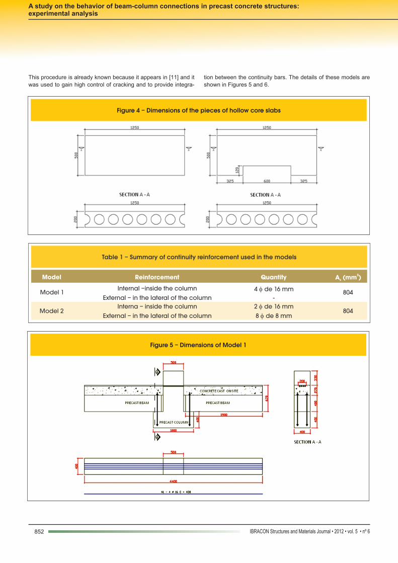
This procedure is already known because it appears in [11] and it was used to gain high control of cracking and to provide integra-
tion between the continuity bars. The details of these models are shown in Figures 5 and 6.
Figure 4 – Dimensions of the pieces of hollow core slabs
Table 1 – Summary of continuity reinforcement used in the models
Model
Reinforcement
Quantity 2A (mm )s
Model 1 Internal –inside the column 4 de 16 mm 804
External – in the lateral of the column -
Model 2 Interna – inside the column 2 de 16 mm
804 External – in the lateral of the column 8 de 8 mm
Figure 5 – Dimensions of Model 1
853IBRACON Structures and Materials Journal • 2012 • vol. 5 • nº 6
M. N. KATAOKA | M. A. FERREIRA | A. L. H. C. EL DEBS
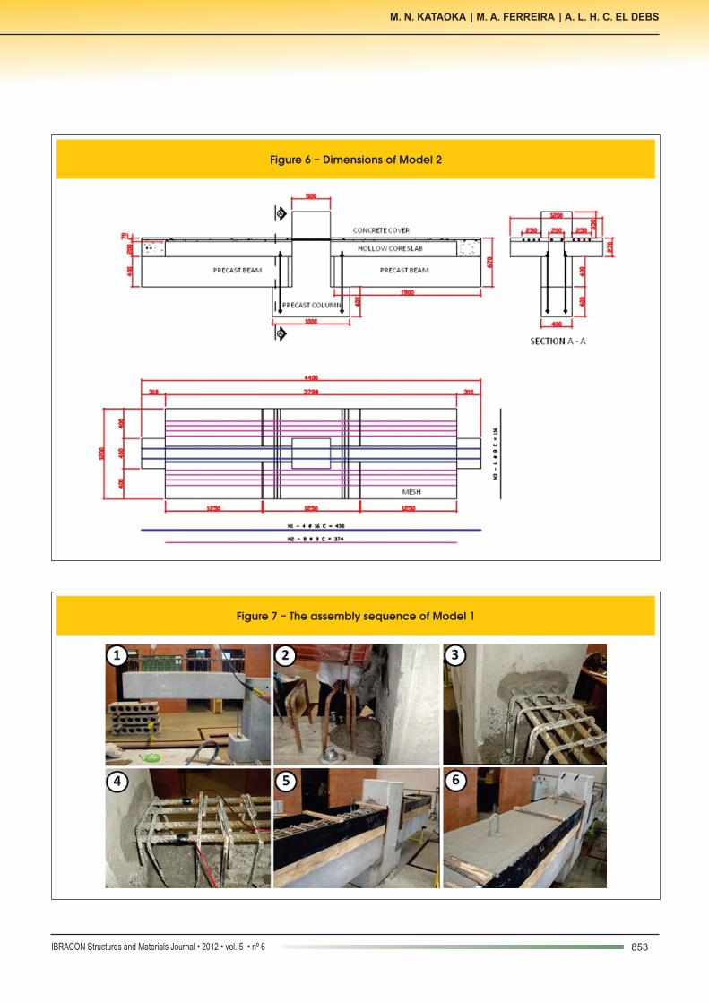
Figure 6 – Dimensions of Model 2
Figure 7 – The assembly sequence of Model 1
854 IBRACON Structures and Materials Journal • 2012 • vol. 5 • nº 6
A study on the behavior of beam-column connections in precast concrete structures: experimental analysis
3.2 Construction of models
The assembly sequence of Model 1 was as follows (Figure 7):1. Attaching the beams in the dowels, which were located in
the corbels;2. Filling the beam-column interface and the hole of the dowels
with grout;3. Placement of continuity reinforcement and filling the column
hole with grout;4. Bonding of strain gages;5. Assembly of timber shapes;6. Concrete casting.The assembly of Model 2 was more complex due to the presence of the slab requires that more time for its construction. Apart from the construction of the slab, the correct positioning of the negative reinforcement also needed to be done with care and precision. The
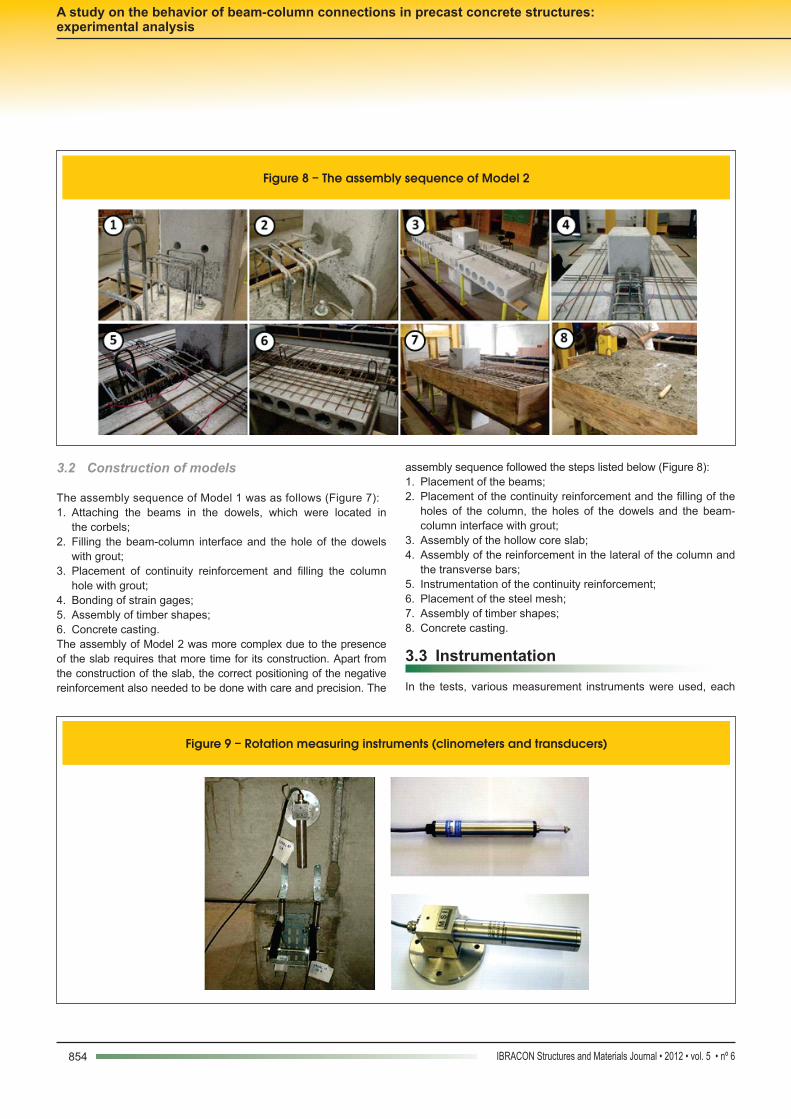
assembly sequence followed the steps listed below (Figure 8):1. Placement of the beams;2. Placement of the continuity reinforcement and the filling of the
holes of the column, the holes of the dowels and the beam-column interface with grout;
3. Assembly of the hollow core slab;4. Assembly of the reinforcement in the lateral of the column and
the transverse bars;5. Instrumentation of the continuity reinforcement; 6. Placement of the steel mesh;7. Assembly of timber shapes;8. Concrete casting.
3.3 Instrumentation
In the tests, various measurement instruments were used, each
Figure 8 – The assembly sequence of Model 2
Figure 9 – Rotation measuring instruments (clinometers and transducers)
855IBRACON Structures and Materials Journal • 2012 • vol. 5 • nº 6
M. N. KATAOKA | M. A. FERREIRA | A. L. H. C. EL DEBS
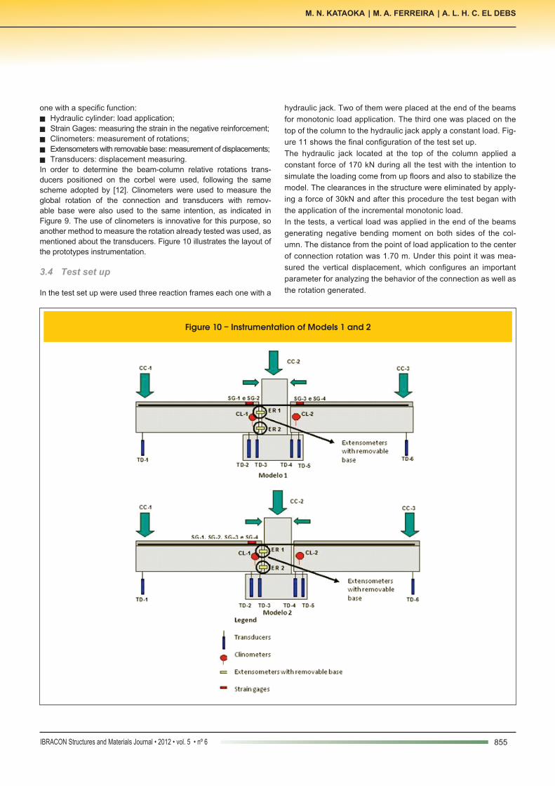
one with a specific function:n Hydraulic cylinder: load application;n Strain Gages: measuring the strain in the negative reinforcement;n Clinometers: measurement of rotations;n Extensometers with removable base: measurement of displacements; n Transducers: displacement measuring.In order to determine the beam-column relative rotations trans-ducers positioned on the corbel were used, following the same scheme adopted by [12]. Clinometers were used to measure the global rotation of the connection and transducers with remov-able base were also used to the same intention, as indicated in Figure 9. The use of clinometers is innovative for this purpose, so another method to measure the rotation already tested was used, as mentioned about the transducers. Figure 10 illustrates the layout of the prototypes instrumentation.
3.4 Test set up
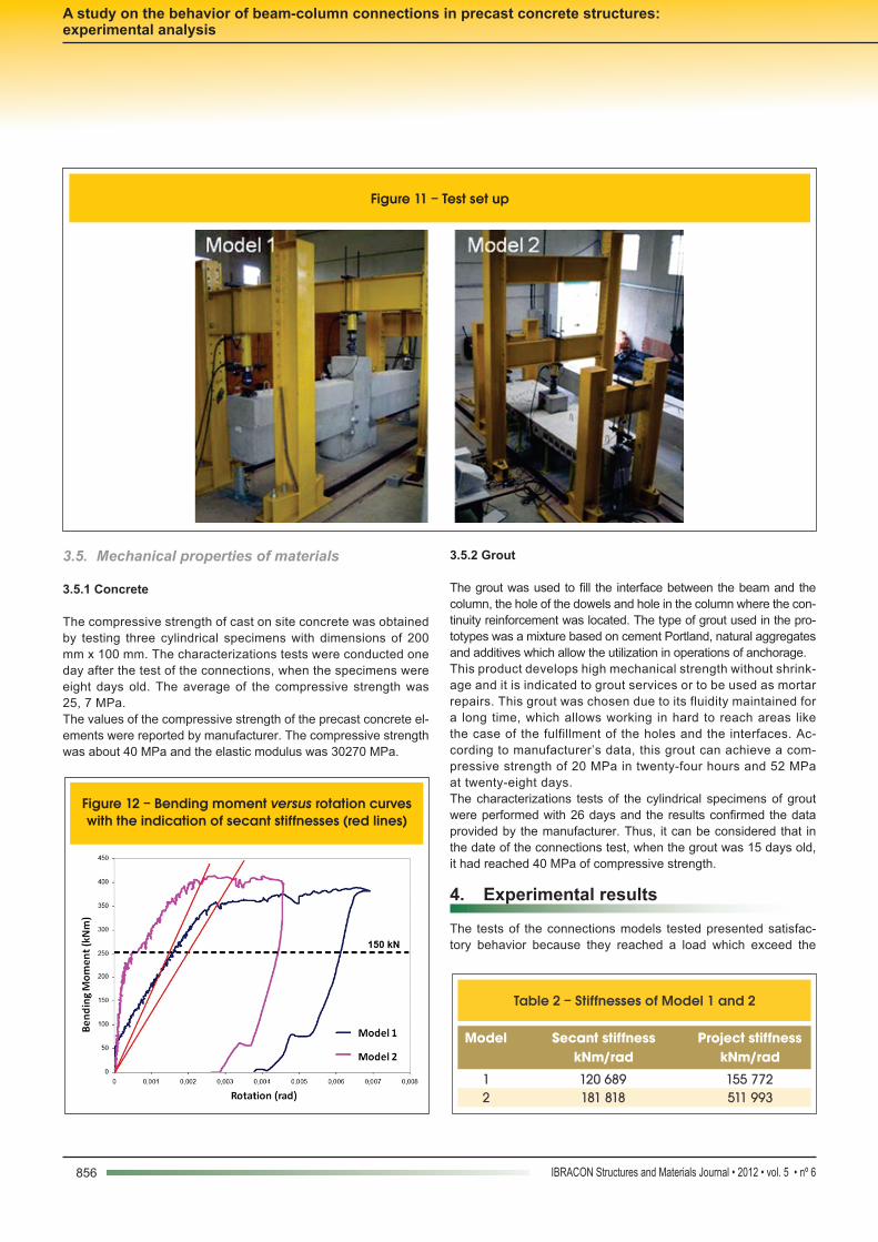
In the test set up were used three reaction frames each one with a
hydraulic jack. Two of them were placed at the end of the beams for monotonic load application. The third one was placed on the top of the column to the hydraulic jack apply a constant load. Fig-ure 11 shows the final configuration of the test set up.The hydraulic jack located at the top of the column applied a constant force of 170 kN during all the test with the intention to simulate the loading come from up floors and also to stabilize the model. The clearances in the structure were eliminated by apply-ing a force of 30kN and after this procedure the test began with the application of the incremental monotonic load.In the tests, a vertical load was applied in the end of the beams generating negative bending moment on both sides of the col-umn. The distance from the point of load application to the center of connection rotation was 1.70 m. Under this point it was mea-sured the vertical displacement, which configures an important parameter for analyzing the behavior of the connection as well as the rotation generated.
Figure 10 – Instrumentation of Models 1 and 2
856 IBRACON Structures and Materials Journal • 2012 • vol. 5 • nº 6
A study on the behavior of beam-column connections in precast concrete structures: experimental analysis
3.5. Mechanical properties of materials
3.5.1 Concrete
The compressive strength of cast on site concrete was obtained by testing three cylindrical specimens with dimensions of 200 mm x 100 mm. The characterizations tests were conducted one day after the test of the connections, when the specimens were eight days old. The average of the compressive strength was 25, 7 MPa.The values of the compressive strength of the precast concrete el-ements were reported by manufacturer. The compressive strength was about 40 MPa and the elastic modulus was 30270 MPa.
3.5.2 Grout
The grout was used to fill the interface between the beam and the column, the hole of the dowels and hole in the column where the con-tinuity reinforcement was located. The type of grout used in the pro-totypes was a mixture based on cement Portland, natural aggregates and additives which allow the utilization in operations of anchorage.This product develops high mechanical strength without shrink-age and it is indicated to grout services or to be used as mortar repairs. This grout was chosen due to its fluidity maintained for a long time, which allows working in hard to reach areas like the case of the fulfillment of the holes and the interfaces. Ac-cording to manufacturer’s data, this grout can achieve a com-pressive strength of 20 MPa in twenty-four hours and 52 MPa at twenty-eight days.The characterizations tests of the cylindrical specimens of grout were performed with 26 days and the results confirmed the data provided by the manufacturer. Thus, it can be considered that in the date of the connections test, when the grout was 15 days old, it had reached 40 MPa of compressive strength. 4. Experimental results
The tests of the connections models tested presented satisfac-tory behavior because they reached a load which exceed the
Figure 11 – Test set up
Figure 12 – Bending moment versus rotation curves with the indication of secant stiffnesses (red lines)
Table 2 – Stiffnesses of Model 1 and 2
Model Secant stiffness kNm/rad
Project stiffnesskNm/rad
1 120 689 155 772 2 181 818 511 993
857IBRACON Structures and Materials Journal • 2012 • vol. 5 • nº 6
M. N. KATAOKA | M. A. FERREIRA | A. L. H. C. EL DEBS
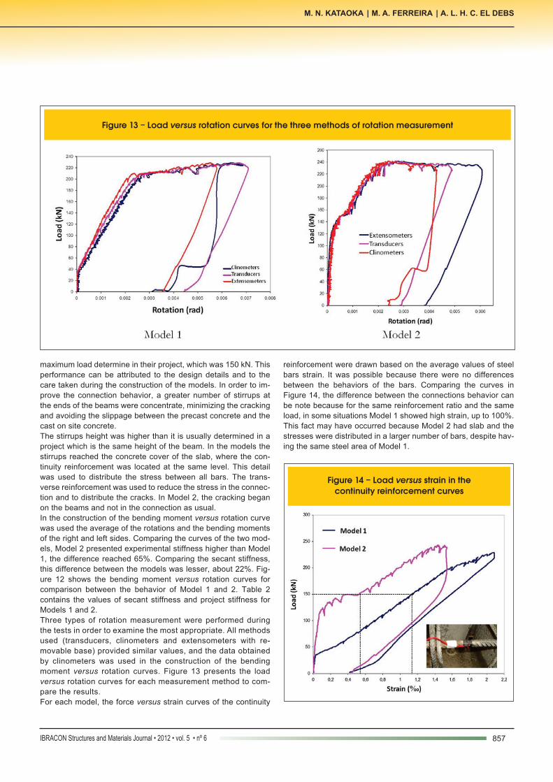
maximum load determine in their project, which was 150 kN. This performance can be attributed to the design details and to the care taken during the construction of the models. In order to im-prove the connection behavior, a greater number of stirrups at the ends of the beams were concentrate, minimizing the cracking and avoiding the slippage between the precast concrete and the cast on site concrete.The stirrups height was higher than it is usually determined in a project which is the same height of the beam. In the models the stirrups reached the concrete cover of the slab, where the con-tinuity reinforcement was located at the same level. This detail was used to distribute the stress between all bars. The trans-verse reinforcement was used to reduce the stress in the connec-tion and to distribute the cracks. In Model 2, the cracking began on the beams and not in the connection as usual.In the construction of the bending moment versus rotation curve was used the average of the rotations and the bending moments of the right and left sides. Comparing the curves of the two mod-els, Model 2 presented experimental stiffness higher than Model 1, the difference reached 65%. Comparing the secant stiffness, this difference between the models was lesser, about 22%. Fig-ure 12 shows the bending moment versus rotation curves for comparison between the behavior of Model 1 and 2. Table 2 contains the values of secant stiffness and project stiffness for Models 1 and 2.Three types of rotation measurement were performed during the tests in order to examine the most appropriate. All methods used (transducers, clinometers and extensometers with re-movable base) provided similar values, and the data obtained by clinometers was used in the construction of the bending moment versus rotation curves. Figure 13 presents the load versus rotation curves for each measurement method to com-pare the results.For each model, the force versus strain curves of the continuity
reinforcement were drawn based on the average values of steel bars strain. It was possible because there were no differences between the behaviors of the bars. Comparing the curves in Figure 14, the difference between the connections behavior can be note because for the same reinforcement ratio and the same load, in some situations Model 1 showed high strain, up to 100%. This fact may have occurred because Model 2 had slab and the stresses were distributed in a larger number of bars, despite hav-ing the same steel area of Model 1.
Figure 13 – Load versus rotation curves for the three methods of rotation measurement
Figure 14 – Load versus strain in the continuity reinforcement curves
858 IBRACON Structures and Materials Journal • 2012 • vol. 5 • nº 6
A study on the behavior of beam-column connections in precast concrete structures: experimental analysis
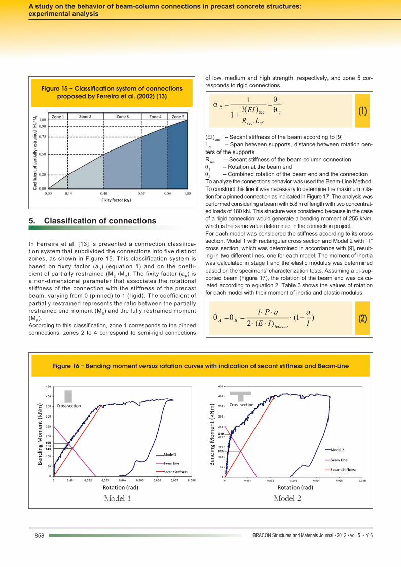
5. Classificationofconnections
In Ferreira et al. [13] is presented a connection classifica-tion system that subdivided the connections into five distinct zones, as shown in Figure 15. This classification system is based on fixity factor (aR) (equation 1) and on the coeffi-cient of partially restrained (ME /MR). The fixity factor (aR) is a non-dimensional parameter that associates the rotational stiffness of the connection with the stiffness of the precast beam, varying from 0 (pinned) to 1 (rigid). The coefficient of partially restrained represents the ratio between the partially restrained end moment (ME) and the fully restrained moment (MR).According to this classification, zone 1 corresponds to the pinned connections, zones 2 to 4 correspond to semi-rigid connections
of low, medium and high strength, respectively, and zone 5 cor-responds to rigid connections.
(1)
2
1
sec
sec
.
)(31
1
ef
R
LR
EI
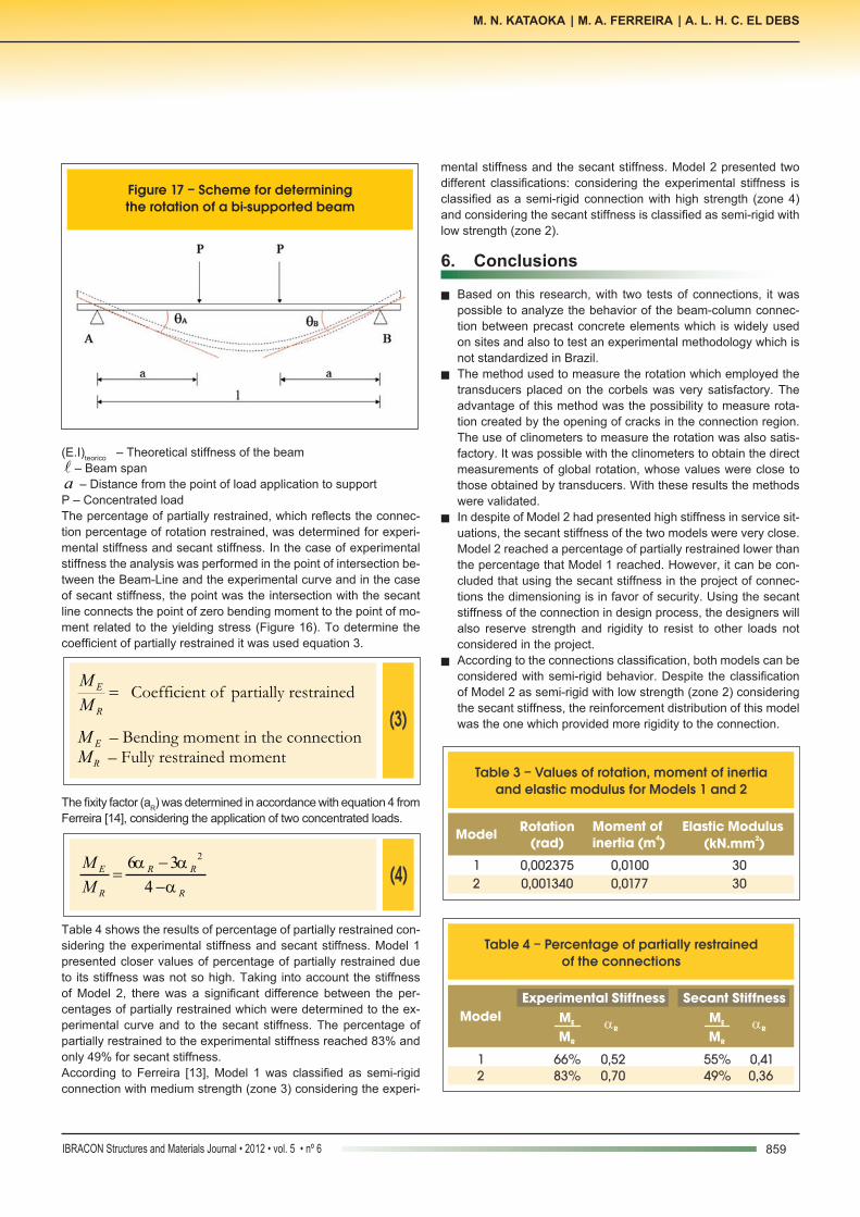
(EI)sec – Secant stiffness of the beam according to [9]Lef – Span between supports, distance between rotation cen-ters of the supportsRsec – Secant stiffness of the beam-column connection q1 – Rotation at the beam endq2 – Combined rotation of the beam end and the connectionTo analyze the connections behavior was used the Beam-Line Method. To construct this line it was necessary to determine the maximum rota-tion for a pinned connection as indicated in Figure 17. The analysis was performed considering a beam with 5.8 m of length with two concentrat-ed loads of 180 kN. This structure was considered because in the case of a rigid connection would generate a bending moment of 255 kNm, which is the same value determined in the connection project. For each model was considered the stiffness according to its cross section. Model 1 with rectangular cross section and Model 2 with “T” cross section, which was determined in accordance with [9], result-ing in two different lines, one for each model. The moment of inertia was calculated in stage I and the elastic modulus was determined based on the specimens’ characterization tests. Assuming a bi-sup-ported beam (Figure 17), the rotation of the beam end was calcu-lated according to equation 2. Table 3 shows the values of rotation for each model with their moment of inertia and elastic modulus.
(2)
)1()(2 l
a
IE
aPl
teorico
BA
Figure 15 – Classification system of connections proposed by Ferreira et al. (2002) [13]
Figure 16 – Bending moment versus rotation curves with indication of secant stiffness and Beam-Line
859IBRACON Structures and Materials Journal • 2012 • vol. 5 • nº 6
M. N. KATAOKA | M. A. FERREIRA | A. L. H. C. EL DEBS
(E.I)teorico – Theoretical stiffness of the beam – Beam spana
– Distance from the point of load application to supportP – Concentrated loadThe percentage of partially restrained, which reflects the connec-tion percentage of rotation restrained, was determined for experi-mental stiffness and secant stiffness. In the case of experimental stiffness the analysis was performed in the point of intersection be-tween the Beam-Line and the experimental curve and in the case of secant stiffness, the point was the intersection with the secant line connects the point of zero bending moment to the point of mo-ment related to the yielding stress (Figure 16). To determine the coefficient of partially restrained it was used equation 3.
(3)
R
E
M
M Coefficient of partially restrained
EM – Bending moment in the connection RM – Fully restrained moment
The fixity factor (aR) was determined in accordance with equation 4 from Ferreira [14], considering the application of two concentrated loads.
(4)
R
RR
R
E
M
M
4
36 2
Table 4 shows the results of percentage of partially restrained con-sidering the experimental stiffness and secant stiffness. Model 1 presented closer values of percentage of partially restrained due to its stiffness was not so high. Taking into account the stiffness of Model 2, there was a significant difference between the per-centages of partially restrained which were determined to the ex-perimental curve and to the secant stiffness. The percentage of partially restrained to the experimental stiffness reached 83% and only 49% for secant stiffness.According to Ferreira [13], Model 1 was classified as semi-rigid connection with medium strength (zone 3) considering the experi-
mental stiffness and the secant stiffness. Model 2 presented two different classifications: considering the experimental stiffness is classified as a semi-rigid connection with high strength (zone 4) and considering the secant stiffness is classified as semi-rigid with low strength (zone 2).
6. Conclusions
n Based on this research, with two tests of connections, it was possible to analyze the behavior of the beam-column connec-tion between precast concrete elements which is widely used on sites and also to test an experimental methodology which is not standardized in Brazil.
n The method used to measure the rotation which employed the transducers placed on the corbels was very satisfactory. The advantage of this method was the possibility to measure rota-tion created by the opening of cracks in the connection region. The use of clinometers to measure the rotation was also satis-factory. It was possible with the clinometers to obtain the direct measurements of global rotation, whose values were close to those obtained by transducers. With these results the methods were validated.
n In despite of Model 2 had presented high stiffness in service sit-uations, the secant stiffness of the two models were very close. Model 2 reached a percentage of partially restrained lower than the percentage that Model 1 reached. However, it can be con-cluded that using the secant stiffness in the project of connec-tions the dimensioning is in favor of security. Using the secant stiffness of the connection in design process, the designers will also reserve strength and rigidity to resist to other loads not considered in the project.
n According to the connections classification, both models can be considered with semi-rigid behavior. Despite the classification of Model 2 as semi-rigid with low strength (zone 2) considering the secant stiffness, the reinforcement distribution of this model was the one which provided more rigidity to the connection.
Figure 17 – Scheme for determining the rotation of a bi-supported beam
Table 3 – Values of rotation, moment of inertia and elastic modulus for Models 1 and 2
Model
Rotation
Moment of 4inertia (m )
Elastic Modulus2(kN.mm )
1
0,002375
0,0100
30 2
0,001340
0,0177
30
(rad)
Table 4 – Percentage of partially restrainedof the connections
Model
Experimental Stiffness Secant Stiffness
MR MR
ME ME RR
1 66% 0,52 55% 0,412 83% 0,70 49% 0,36
860 IBRACON Structures and Materials Journal • 2012 • vol. 5 • nº 6
A study on the behavior of beam-column connections in precast concrete structures: experimental analysis
7. Acknowledgments
The authors would like to thank FAPESP by financial support and Protendit by donation of the precast elements that allow the con-struction of the models.
8. References
[01] ASSOCIAÇÃO BRASILEIRA DE NORMAS TÉCNICAS. NBR 9062. (2006). Projeto e Execução de Estruturas
de Concreto Pré-moldado. Rio de Janeiro – RJ. [02] SHARIATMADAR, H., BEYDOKHTI, E. Z. (2011). Experimental investigation of precast concrete beam
to column connections subjected to reversed cyclic loads. 6th International Conference on Seismology and Earthquake Engineering. Tehran, Iran.
[03] HAWILEH, R. A.; RAHMAN, A.; TABATABAI, H. (2010). Nonlinear finite element analysis and modeling of a precast hybrid beam–column connection subjected to cyclic loads. Applied Mathematical Modelling. [04] KAYA, M.; ARSLAN, S. (2009). Analytical modeling of post-tensioned precast beam-to-column connections. Materials and Design. [05] SAQAN, E. I. (1995). Evaluation of ductile beam-column connections for use in seismic-resistant precast
frames. Ph.D Thesis. Faculty of the Graduate School of The University of Texas at Austin.
[06] OLIVEIRA JÚNIOR, L. A. (2012). Ligação viga-pilar em elemento pré-moldado de concreto solidarizados por concreto reforçado com fibras de aço: análises
estática e dinâmica. Tese de Doutorado. Escola de Engenharia de São Carlos, Universidade de São Paulo.
São Carlos. 255p. [07] BALDISSERA, A. (2006). Estudo experimental de uma ligação viga-pilar de concreto pré-moldado parcialmente resistente a momento fletor. Dissertação de Mestrado. Escola de Engenharia de São Carlos –
Universidade de São Paulo. São Carlos – SP. [08] KATAOKA, M. N. (2007). Estudo da continuidade em
ligações laje-viga-pilar em estruturas pré-moldadas de concreto. Dissertação de Mestrado. Universidade
Federal de São Carlos. São Carlos – SP. 113p. [09] ASSOCIAÇÃO BRASILEIRA DE NORMAS TÉCNICAS. NBR-6118. (2003). Projeto e Execução de Obras de
Concreto Armado. Rio de Janeiro – RJ. [10] EL DEBS, M, K. (2000). Concreto pré-moldado: fundamentos e aplicações, 1ª Edição, EESC – USP,
São Carlos, 456 p. [11] COST-C1 (1996). European Cooperation in the Field
of Scientific and Technical Research. Semi-rigid behaviour of civil engineering structural connections -
Composite steel-concrete joints in braced frames for buildings. Bruxelas, Luxemburgo.
[12] CHEFDEBIEN, A. (1998). Precast concrete beam to column head connections. In: CONTROL OF THE
SEMI-RIGID BEHAVIOUR OF CIVIL ENGINEERING STRUCTURAL CONNECTIONS, COST C1
INTERNACIONAL CONFERENCE. Cost C1: Proceedings. Liege, Belgium. P. 35-43.
[13] FERREIRA, M. A.; El Debs, M. K.; Elliott, K. S. (2002). Modelo teórico para projeto de ligações semi-rígidas
em estruturas de concreto pré-moldado. 44º Congresso Brasileiro do Concreto – IBRACON. Agosto, Belo Horizonte – MG. [14] FERREIRA, M. A, (2006). Study on the semi-rigid behaviour of beam-column connections in precast
concrete structures. FAPESP Annual Research Report Brazil.