A STUDY OF THE MECHANICAL PROPERTIES OF CRUMB …
83
A STUDY OF THE MECHANICAL PROPERTIES OF CRUMB RUBBER LIGHTWEIGHT FOAMED CONCRETE WITH DENSITY OF 1100-1200 KG/ M 3 OON KEL LEE A project report submitted in partial fulfilment of the requirements for the award of Bachelor of Engineering (Honours) Civil Engineering Lee Kong Chian Faculty of Engineering and Science Universiti Tunku Abdul Rahman April 2020
Transcript of A STUDY OF THE MECHANICAL PROPERTIES OF CRUMB …

A STUDY OF THE MECHANICAL PROPERTIES OF CRUMB
RUBBER LIGHTWEIGHT FOAMED CONCRETE WITH DENSITY
OF 1100-1200 KG/ M3
OON KEL LEE
A project report submitted in partial fulfilment of the
requirements for the award of Bachelor of Engineering
(Honours) Civil Engineering
Lee Kong Chian Faculty of Engineering and Science
Universiti Tunku Abdul Rahman
April 2020

i
DECLARATION
I hereby declare that this project report is based on my original work except for
citations and quotations which have been duly acknowledged. I also declare
that it has not been previously and concurrently submitted for any other degree
or award at UTAR or other institutions.
Signature :
Name : OON KEL LEE
ID No. : 15UEB01502
Date : 22nd April 2020

ii
APPROVAL FOR SUBMISSION
I certify that this project report entitled “A STUDY OF THE MECHANICAL
PROPERTIES OF CRUMB RUBBER LIGHTWEIGHT FOAMED
CONCRETE WITH DENSITY OF 1100-1200 KG/M3” was prepared by
OON KEL LEE has met the required standard for submission in partial
fulfilment of the requirements for the award of Bachelor of Engineering
(Honours) Civil Engineering at Universiti Tunku Abdul Rahman.
Approved by,
Signature :
Supervisor : Dr. Lee Foo Wei
Date : 22nd April 2020

iii
The copyright of this report belongs to the author under the terms of the
copyright Act 1987 as qualified by Intellectual Property Policy of Universiti
Tunku Abdul Rahman. Due acknowledgement shall always be made of the use
of any material contained in, or derived from, this report.
© 2020, Oon Kel Lee. All right reserved.

iv
ACKNOWLEDGEMENTS
I would like to thank everyone who had contributed to the successful completion
of this project. I would like to express my gratitude to my research supervisor,
Dr. Lee Foo Wei for his invaluable advice, guidance and his enormous patience
throughout the development of the research.
In addition, I would also like to express my gratitude to Leon Lim, my
senior who guided me throughout this project and taught me a lot about concrete
behaviours. Then my friend, Ooi Wei Chien, who sacrificed his time helping
me to cast seventeen sets of concrete during the semester break even though he
was busy with his post graduate studies. Lastly, my loving parents who had
helped and given me encouragement.

v
ABSTRACT
For the past few decades, the disposal of waste tyres has become a serious
environmental problem as a huge amount of scrap tyres are being generated
worldwide. Many researchers had been studying this issue and actions had been
made. It appears that recycling scrap tyres were the best and most effective
solution for disposing of this material due to its economic and ecological
advantages. This study was carried out to study on the feasibility of using crumb
rubber particles as a partial replacement of fine aggregates in lightweight
foamed concrete. Besides, it could be a benchmark for future studies in this field
to accommodate a better and more sustainable production of building insulators.
The mechanical properties such as the compressive strength, tensile strength
and flexural strength of crumb rubber lightweight foamed concrete were tested
based on the ASTM standards. Two sizes of crumb rubber particles were used
in this study, namely, the granular crumb rubber (1 - 4 mm) and powdered
crumb rubber particles (40 mesh). This study has proven that the utilization of
granular and powdered crumb rubber in lightweight foamed concrete could
affect the mechanical properties like the compressive, splitting tensile and the
flexural strength. The highest compression and tensile strengths of 20 %
granular crumb rubber lightweight foamed concrete (GCLFC) were reported
with a value of 2.930 MPa and 0.399 MPa while the highest flexural strength
obtained from 10 % of crumb rubber replacement was 2.248 MPa. The
mechanical strength of GCLFC had increased by 10.27 % (compressive), 21.65
% (splitting tensile) and 2.97 % (flexural) compared with the controlled mix
specimens. However, as the crumb rubber proportion of GCLFC increases more
than 20 %, a significant reduction of mechanical strength was noticed. On the
other hand, the powdered crumb rubber lightweight foamed concrete (PCLFC)
has the highest compressive and splitting tensile strength at 70 % of crumb
rubber proportion with the values of 3.227 MPa and 0.533 MPa whereas the
highest flexural strength is at 80 % of crumb rubber proportion with a value of
2.829 MPa. In a nutshell, PCLFC has better improvement in the mechanical
strength as it has increased by 3.01 % to 33.87 % (compressive), 2.44 % to 62.5
% (splitting tensile) as well as 6.7 % to 29.6 % (flexural) compared to the
controlled mix.
vi
TABLE OF CONTENTS
DECLARATION i
APPROVAL FOR SUBMISSION ii
ACKNOWLEDGEMENTS iv
ABSTRACT v
TABLE OF CONTENTS vi
LIST OF TABLES ix
LIST OF FIGURES x
LIST OF SYMBOLS / ABBREVIATIONS xiii
CHAPTER
1 INTRODUCTION 1
1.1 Background 1
1.2 Problem Statement 2
1.3 Aim and Objectives 3
1.4 Scope and Limitation of the Study 4
1.5 Significance of Study 5
1.6 Outline of the Report 5
2 LITERATURE REVIEW 7
2.1 Introduction 7
2.2 Lightweight Foamed Concrete (LFC) 7
2.3 Applications of Crumb rubber Lightweight
Foamed Concrete (CRLFC) 8
2.4 Advantages of Using Crumb Rubber in Concrete 10
2.5 Disadvantages of Using Crumb Rubber in
Concrete 11
2.6 Materials 12
2.6.1 Rubber Aggregates 12
2.6.2 Type I Ordinary Portland cement (OPC) 14
2.6.3 Aggregate 15

vii
2.6.4 Silica Fume 15
2.6.5 Air-entraining agent 17
2.7 The Properties of Crumb Rubber Lightweight
Aggregate Concrete 17
2.7.1 Compressive Strength 18
2.7.2 Splitting Tensile Strength 19
2.7.3 Flexural Strength 20
2.7.4 Impact Resistance 21
2.7.5 Modulus of Elasticity 21
2.7.6 Freeze-thaw resistance 22
2.8 Summary 23
3 METHODOLOGY AND WORK PLAN 25
3.1 Introduction 25
3.2 Raw Materials 26
3.2.1 Ordinary Portland Cement (OPC) 26
3.2.2 Silica Fume 26
3.2.3 Fine Aggregate 27
3.2.4 Crumb Rubber 28
3.2.5 Foaming Agent 29
3.2.6 Water 31
3.3 Mould 31
3.4 Mix Proportions 31
3.5 Mixing Procedure 35
3.6 Casting 37
3.7 Curing 37
3.7.1 Density Test 38
3.8 Hardened Concrete Test 39
3.8.1 Compressive Strength 39
3.8.2 Splitting Tensile Strength 41
3.8.3 Flexural Strength 42
3.9 Summary 44
4 RESULTS AND DISCUSSION 45
4.1 Introduction 45
4.2 Mechanical Properties Test 45

viii
4.2.1 Compressive Strength Test 46
4.2.2 Splitting Tensile Strength 51
4.2.3 Flexural Strength 57
4.3 Summary 62
5 CONCLUSIONS AND RECOMMENDATIONS 64
5.1 Conclusions 64
5.2 Recommendations for Future Work 65
REFERENCES 66
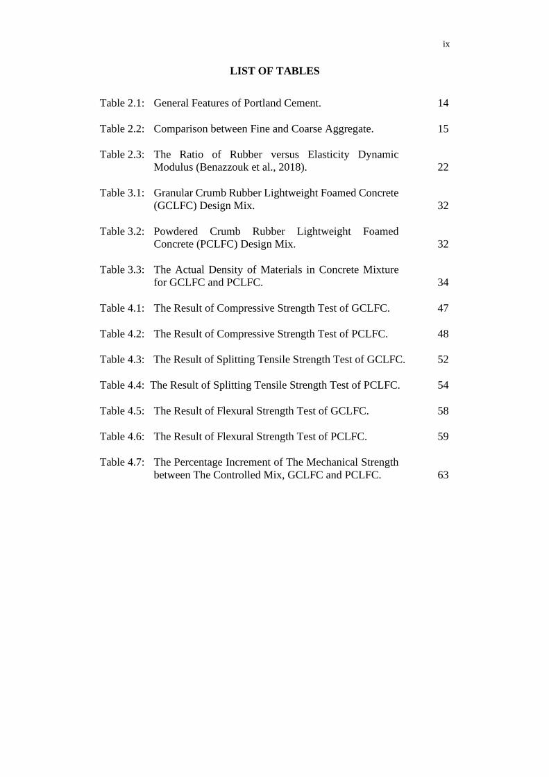
ix
LIST OF TABLES
Table 2.1: General Features of Portland Cement. 14
Table 2.2: Comparison between Fine and Coarse Aggregate. 15
Table 2.3: The Ratio of Rubber versus Elasticity Dynamic
Modulus (Benazzouk et al., 2018). 22
Table 3.1: Granular Crumb Rubber Lightweight Foamed Concrete
(GCLFC) Design Mix. 32
Table 3.2: Powdered Crumb Rubber Lightweight Foamed
Concrete (PCLFC) Design Mix. 32
Table 3.3: The Actual Density of Materials in Concrete Mixture
for GCLFC and PCLFC. 34
Table 4.1: The Result of Compressive Strength Test of GCLFC. 47
Table 4.2: The Result of Compressive Strength Test of PCLFC. 48
Table 4.3: The Result of Splitting Tensile Strength Test of GCLFC. 52
Table 4.4: The Result of Splitting Tensile Strength Test of PCLFC. 54
Table 4.5: The Result of Flexural Strength Test of GCLFC. 58
Table 4.6: The Result of Flexural Strength Test of PCLFC. 59
Table 4.7: The Percentage Increment of The Mechanical Strength
between The Controlled Mix, GCLFC and PCLFC. 63

x
LIST OF FIGURES
Figure 2.1: Rubber Concrete Pad Foundation. 9
Figure 2.2: Precast Rubber Concrete Road Barrier. 9
Figure 2.3: Rubber Concrete Wall Panels. 10
Figure 2.4: The Effect of Slump flow versus The Percentage of
Rubber (Abdullah, 2017). 12
Figure 2.5: Rubber Aggregates: (1) Shredded, (2) Crumb, (3)
Ground, and (4) fibre (Nakim, et al., 2010). 13
Figure 2.6: Benefits of Silica Fume (Sharm, et al., 2014). 16
Figure 2.7: The Compressive Strength versus Replacement Level
of Rubber (Lv, 2015). 19
Figure 2.8: The Splitting Tensile Strength against The Level of
Replacement of Rubber (Lv, 2015). 20
Figure 2.9: The Flexural Strength versus Rubber Content (Topcu,
et al., 1997). 21
Figure 2.10: Result of Freeze-thaw Resistance (Girkas and
Nagrockiene, 2017). 23
Figure 3.1: Flow Chart of Overall Research. 25
Figure 3.2: The Ordinary Portland Cement, ‘Orang Kuat’ brand
from YTL Sdn. Bhd. 26
Figure 3.3: Silica Fume from Scancem Materials. 27
Figure 3.4: Sieved Sand in a Container. 27
Figure 3.5: Granular Crumb Rubber Particles. 28
Figure 3.6: Powdered Crumb Rubber Particles. 28
Figure 3.7: The Foaming Agent - SikaAER@ - 50/50. 29
Figure 3.8: Foam Generator. 30
Figure 3.9: Generated Foam. 30
Figure 3.10: Flow of The Mixing Procedures of Crumb Rubber
Lightweight Foamed Concrete. 36

xi
Figure 3.11: Casting of Concrete. 37
Figure 3.12: Curing Process of Concrete Specimens. 38
Figure 3.13: Fresh Density Test of Fresh Concrete. 38
Figure 3.14: Compression Test in Compression Machine AD
300/EL Digital Readout 3000 kN. 40
Figure 3.15: The Machine Setup for the Rate of Compressive
Strength. 41
Figure 3.16: The Placing of Cylindrical Specimen for Splitting
Tensile Strength Test. 41
Figure 3.17: Illustration of The Tensile Test on Concrete
(Hamakareem, 2016). 42
Figure 3.18: Prism Mould. 43
Figure 3.19: The Concrete Set Up on the Flexural Machine. 43
Figure 4.1: Compressive Strength versus Percentage of Granular
Crumb Rubber Proportion – GCLFC. 47
Figure 4.2: Compressive Strength versus The Percentage of
Crumb Rubber – PCLFC. 49
Figure 4.3: The Relationship between The Compressive Strength
of GCLFC and PCLFC. 50
Figure 4.4: Splitting Tensile Strength versus The Percentage of
Crumb Rubber – GCLFC. 52
Figure 4.5: Splitting Tensile Strength versus The Percentage of
Crumb Rubber -PCLFC. 54
Figure 4.6: The Relationship between The Splitting Tensile
Strength of GCLFC and PCLFC. 55
Figure 4.7: Concrete Failure of GCLFC. 56
Figure 4.8: Concrete Failure of PCLFC. 56
Figure 4.9: Flexural Strength versus The Percentage of Crumb
Rubber – GCLFC. 58
Figure 4.10: Flexural Strength versus The Percentage of Crumb
Rubber – PCLFC. 60

xii
Figure 4.11: The Relationship between The Flexural Strength of
GCLFC and PCLFC. 61
Figure 4.12: Comparison of The Mechanical Strength Results for
GCLFC and PCLFC. 63

xiii
LIST OF SYMBOLS / ABBREVIATIONS
P Maximum Load Applied, N
F Compressive Strength, MPa
A Cross-section Area of the Concrete Cube, m2
R Flexural Strength, MPa
L Maximum Span Length, mm
b Average Specimen Width, mm
d Average Specimen Depth, mm
T Splitting Tensile Strength, MPa
D Diameter of the Specimen, m
C3A Tricalcium Aluminate
C2S Dicalcium Silicate
C3S Tricalcium Silicate
C4AF Tetra Calcium Alumina Ferrite
MgO Magnesium Oxide
CaO Calcium Oxide
LFC Lightweight Foamed Concrete
GCLFC Granular Crumb Rubber Lightweight Foamed Concrete
PCLFC Powdered Crumb Rubber Lightweight Foamed Concrete
OPC Ordinary Portland Cement

1
CHAPTER 1
1 INTRODUCTION
1.1 Background
Concrete is found to be one of the most typical materials in the construction
industry. The main components of concrete contain coarse or fine aggregates,
Portland cement (limestone) and water. The quality and strength of the concrete
vary with respect to the mixing proportion of concrete. Concrete has been used
in various applications and it is considered as very affordable, especially in the
construction industry (Mehta, 1986). Today, a wide variety of applications have
adopted this material, for example, dams, foundations, pavements, storage tanks,
bridges, drains and multi-storey buildings. In the construction sector, many
industries had shown significant progress throughout the year, together with the
development of ready-mixed concrete. (Topçu and Bilir, 2009).
With the growth of concrete technology in the industry, various types of
concrete can be found in the market nowadays (Neville and Brooks, 1987). The
types of conventional concrete available such as lightweight concrete, high
strength concrete, asphalt concrete, crumb rubber lightweight foamed concrete
and polymer concrete can be easily obtained from the market. Furthermore, the
research and development of the concrete have been widely expanded towards
more environmentally-friendly in the past few years (Shetty, 2008). By
replacing a portion of aggregates in finer size with recycled waste tyres in
concrete can provide adequate strength for the concrete to perform and yet
decrease the waste issues (Kaloush, et al., 2005). This alternative way of
recycling waste tyres has been strongly recommended. This research had been
conducted by many researchers and many findings had been discovered over the
past few decades.
The mixture of air-entraining admixture in cement is able to produce
lightweight foamed concrete (Amran, et al., 2015). The purpose of air-
entraining reagent is to induce tiny air bubbles within the concrete particles.
There are several characteristics of lightweight foamed concrete. For instance,
it can be easily fabricated, possesses excellent thermal and acoustic insulation.
So far, in civil engineering works, the main purpose of this material is used as a

2
filler material. Nonetheless, it has a strong potential of being used as a building
material in constructions in terms of its good thermal and acoustic performance.
Even though lightweight foamed concrete contains lower mechanical
properties compared to ordinary concrete, it still can serve many purposes in the
construction industry (Bing, et al., 2012). For example, in low-rise residential
construction, it can be used as the light load walls as well as a partition between
rooms. Besides that, they are so much lighter compared to concrete with average
weight. Hence, adopting it in structural elements could greatly reduce the
column, footing and loading bearing due to a lower structural dead load (Mehta
and Monteiro, 2001).
Today, a new development in material technologies had been picked up.
It appears that recycled waste tyres could be used in the concrete as it provides
several improvements in the ductility, sound absorption, toughness and the
freeze-thaw resistance despite the reduction in mechanical properties (Khaloo,
et al., 2008). However, there would be a potential improvement in the
mechanical properties of concrete when waste tyres are mixed with lightweight
foamed concrete (Youssf, et al., 2014). Buildings made of recycled tyre concrete
will result in less energy consumption. Moreover, utilising recycled tyres in
concrete composites by replacing the fine aggregates partially have the
capability of reducing the overall greenhouse gases (GSG) emission on Earth,
provide numerous potential economic advantages as well as reducing
environmental problems that correlate with the waste tyres as compared to
ordinary concrete (Meyer, 2009).
Lastly, to solve the environmental issues related to waste tyres, the study
of utilizing crumb rubber particles in lightweight foamed concrete had been
carried out and laboratory experiments had been conducted. Besides that,
several types of research had been outlining the crumb rubber particles usage in
concrete as it has the potential to be used in various applications in the
construction field (Benazzouk, 2008).
1.2 Problem Statement
Today, waste material production is soaring at an alarming pace. An
approximation of 8 billion waste tyres was produced worldwide today. Not only

3
that, but this situation also became severe as the amount keeps increasing
nonstop and it is mirrored in many countries around the globe.
According to Kumar (2013), Malaysia had generated an estimation of
8.2 million waste tyres throughout the years and the total wastes produced in
this country could go up to approximately 57,000 tonnes annually.
Consequently, sustainable methods on recycling and managing this vast amount
of wastes are absolutely essential to prevent any serious pollution from
occurring. The environment will be critically polluted if the enormous amount
of rubber tyres is not adequately reprocessed and disposed of. Therefore, a few
solutions such as reusing tyres from second-hand market and rethreading,
recovery of material from chopped, shredded, whole and micronized tyres and
recovering of energy can be adopted worldwide (Thomas, et al., 2015).
One of the feasible solutions to the reduction of wastes is using recycled
crumb rubber particles in concrete. It helps in the improvement of concrete
properties, transforming it to become more flexible as a material (Batayneh, et
al., 2008). Besides that, using recycled tyres in construction components is a
green alternative for saving the environment and reusing waste (Aiello and
Leuzzi, 2010). Throughout the years, extensive research had been made
covering the use of crumb rubber particles in ordinary concrete as a filler
material (Issa and Salem, 2013). In this study, findings stated that the crumb
rubber particles could be used as the replacement for fine aggregates in the
lightweight foamed concrete. The effects of crumb rubber contents on the
mechanical properties of lightweight foamed concrete are studied.
1.3 Aim and Objectives
This study aims to produce crumb rubber lightweight foamed concrete with a
density of 1100 to 1200 kg/m3.
To attain the aim, there are several objectives required to be listed out:
I. To determine the effect of different proportion (0 – 80 %) of crumb
rubber on the mechanical properties, namely the splitting tensile,
compressive and flexural strength of crumb rubber lightweight foamed
concrete.

4
II. To obtain the optimum mix proportion of granular and powdered crumb
rubber particles in the lightweight foamed concrete based on the highest
mechanical strength.
III. To compare the performance of crumb rubber particle size (1 to 4 mm
and 40 mesh) on the mechanical properties, namely the splitting tensile,
compressive and flexural strength of crumb rubber lightweight foamed
concrete.
1.4 Scope and Limitation of the Study
The current research was performed using a small-scale experimental approach.
The scope of this research emphasizes the mechanical strength properties of
crumb rubber lightweight foamed concrete with the density ranging from 1100
kg/m3 to 1200 kg/m3. Three laboratory tests will be carried out in order to
determine the crumb rubber lightweight foamed concrete mechanical properties
which are the flexural, compressive and the splitting tensile test. Besides, the
reason for conducting these three tests is to find out whether the concrete
strength could achieve the ASTM standard and requirements.
To carry out the research, a few limitations have to be justified. Firstly,
the water-cement ratio was fixed at 0.60. Next, the fine aggregates will be
replaced with two different sizes of crumb rubber particles, which are the
granular and powdered crumb rubber. Both had a mix proportion ranging from
0 % to 80 % respectively, with 10 % intervals. These trial mixes were prepared
to find out the optimum proportion for the crumb rubber lightweight foamed
concrete to perform at its best. Seventeen sets of mixes were produced
throughout this experimental work.
Three main concrete tests were conducted after 28 days of water curing
treatment. For each proportion of crumb rubber lightweight foamed concrete,
the compressive strength test was performed on three cubic specimens with the
dimension of 100 mm in length, 100 mm in width and 100 mm in height.
Splitting tensile test was carried out with three cylindrical specimens, and the
flexural strength was obtained by testing three prism specimens with a
dimension of 160 mm (l) x 40 mm (w) x 40 mm (h).

5
1.5 Significance of Study
For this research, the importance of the study is as follow:
1. To promote the use of rubber particles from waste tyres in concrete. This
environmentally-friendly concrete product could help reduce the waste
tyres around us as well as reducing the unnecessary waste disposal on
Earth.
2. Adding crumb rubber particles in lightweight foamed concrete could
minimize the environmental issues regarding waste tyres and improve
mechanical strength. Hence, it could be applied in construction elements
while achieving ecological and economic advantages.
3. This study can be adopted as a benchmark for future studies in this field
to accommodate a better and more sustainable production of building
insulators for sound and thermal as well to enhance the green technology
and green materials in the construction industry.
1.6 Outline of the Report
A total number of 5 chapters are included in this study.
Chapter 1 covers the introduction of the study, which explains about the
crumb rubbers in lightweight foamed concrete. Besides, this chapter also
consists of the background, problem statement, aim and objectives, study scope,
the significance of the study as well as the report layout.
Chapter 2 is the literature review, which contains the previous researches
on lightweight foamed concrete and its applications. The use of silica fume is
also explained briefly. Chapter 2 also covers the pros and cons of using crumb
rubber particles in concrete mixtures, the properties of crumb rubber lightweight
aggregate concrete, materials used for producing crumb rubber lightweight
foamed concrete and also the engineering testing.
Chapter 3 is the methodology, which outlines the steps of conducting the
tests. This chapter consists of the materials, procedures and the mix proportions
of crumb rubber lightweight foamed concrete are stated step by steps. Besides
that, the details of the test method and procedures are discussed in this chapter.
Chapter 4 is the data presentation; it consists of the data analysis from
the three mechanical property tests that had been carried out. A thorough
discussion was conducted in this chapter by comparing the results with the
6
different proportion and different sizes of crumb rubber used in lightweight
foamed concrete and its strength.
Chapter 5 concludes the overall study of this research. The conclusion
of the objectives for this study and some recommendations to improve the
outcomes were discussed.

7
CHAPTER 2
2 LITERATURE REVIEW
2.1 Introduction
This chapter contributes an overview of the publication of articles relating to the
objectives of this report. Firstly, the use of silica fume is briefly explained and
the pros and cons of using crumb rubber in concrete are listed in details. The
lightweight foamed concrete and its application is explained clearly. The
properties of crumb rubber lightweight aggregate concrete are studied and
reviewed. Last but not least, the comparison of materials to produce the crumb
rubber lightweight foamed concrete was thoroughly reviewed. Material
recovery of adding crumb rubber into lightweight foamed concrete is
approached in this study.
2.2 Lightweight Foamed Concrete (LFC)
In this era, lightweight foamed concrete has the potential to be used in various
applications. It has a huge advantage of being lighter than normal concrete. The
range for its density is 300 to 1800 kg/m3 (Amarnath, 2013). Besides that,
lightweight foamed concrete of different densities can be produced by
supervising the foam dosage added into the mixture of concrete. It can be used
for the construction of numerous structural buildings, filling grades or the
thermal insulation wall.
By comparing with normal concrete, lightweight foamed concrete is
mostly used in non-loaded bearing applications as it reduces the dead load of
structures such as the steel reinforcement required for beam, slab or column in
a building which indirectly reduces the cost of the project and makes the design
of supporting structures more economical. Besides, it has the properties of
having a good thermal insulation, fire resistance, low density and stiffness.
Nowadays, lightweight foamed concrete is an innovative technology and
it is quite popular in the construction field. The high-workability property of
lightweight foamed concrete produces a well-bonded body. Hence, concrete
will not settle that quickly and no compaction is needed. Besides that, the
8
lightweight foamed concrete does not need imposing lateral forces due to its
excellent load distribution and high flow ability under fresh condition. However,
the foamed concrete is very sensitive to water ratio, and it could take some time
during the mixing phase.
2.3 Applications of Crumb rubber Lightweight Foamed Concrete
(CRLFC)
Crumb rubber lightweight foamed concrete is expected to become increasingly
well-known in plenty of the construction industry due to its typical properties
which include good sound insulation, high thermal insulation and low density.
In fact, its great flow ability has provided construction industries to undergo
their projects with lesser efforts and also costs. Over the past 20 years, several
researchers had outlined some suggestions and the potential usage of crumb
rubber lightweight concrete in our daily life. The most beneficial potential for
using industrial wastes is the impacts on the environment. Hence, the
application of crumb rubber in lightweight foamed concrete is capable of
stimulating the economy, especially in construction industries and reducing
wastelands (Md Noor, et al., 2016).
Firstly, rubber is a great vibration resisting agent and it has the ability to
absorb the impact of forces (Ganjian, et al., 2009). Hence, adding it in
lightweight foamed concrete can produce a new type of concrete that can be
used as foundation pads, capable of reducing the impact of large forces or in the
walls of railway stations to reduce the vibrations and noise of the fast-moving
train (Fattuhi and Clark, 1996).

9
Figure 2.1: Rubber Concrete Pad Foundation (Uddin, 2018).
In addition, the insulation of thermal in concrete panels can be improved
significantly by utilising crumb rubber particles in concrete depending on the
proportion and particle size (Sunthonpagasit and Duffey, 2004). Researchers
had shown that higher levels of sound absorption could be achieved in crumb
rubber lightweight foamed concrete and the overall reduction of noise is 36 %
(Najim and Hall, 2010). Thus, the usage of crumb rubber lightweight foamed
concrete could be considered in highway constructions for their coating and
road barriers.
Figure 2.2: Precast Rubber Concrete Road Barrier (Whisper, 2015).

10
Also, crumb rubber lightweight foamed concrete can be utilised in
architectural applications where high strength is not required like the nailing
concrete, where only low unit weight is necessary such as in wall panels, as well
as in barriers and elements of construction that are subjected to impact forces.
Figure 2.3: Rubber Concrete Wall Panels (Europages, 2017).
Lastly, sound absorptive walls can be produced using crumb rubber
foamed concrete. Although this type of wall is expensive compared to normal
walls, however, they are more efficient in absorbing sound (Sukontasukul,
2009). For instance, Smart Wall is a concrete panel system that uses rubber
particles to replace fine aggregates in its concrete mix. It consists of elements
with bulging angled surface designed to lower direct reflections of sound and
therefore reduces the noise (Farraq, 2016).
2.4 Advantages of Using Crumb Rubber in Concrete
There are several advantages of using crumb rubber concrete instead of plain
concrete. Firstly, it helps to reduce the amount of cracking in roads, bridges and
structures. To improve the long-term quality of a structure, it is essential to
recognize the use of wastes tyres in construction. Otherwise, the large number
of scrap tyres would end up in the landfill (Cierra, 2017). Besides that, although
replacing crumb rubber as lightweight aggregates in concrete significantly
reduces the strength, nonetheless, many studies conducted by researchers had

11
shown an improvement in certain durability properties of using crumb rubber in
concrete mixtures (Pierce and Blackwell, 2003).
Additionally, reducing the weight of concrete can reduce the cost of
construction. However, the strength required must be maintained to support the
concrete to work. Next, crumb rubber concrete tends to have improved acoustic
insulation and thermal conductivity compared to normal concrete. Moreover,
using rubber in concrete will enhance the shock resistance, absorption capability,
extensibility and ductility of the concrete (Kaloush and Way, 2005). Lastly,
crumb rubber is encouraged to be used in concrete as it helps to absorb impacts
since rubbers have the capability of softening concrete as well as yielding a
greater plastic deformation (Atahan and Yücel, 2012).
2.5 Disadvantages of Using Crumb Rubber in Concrete
Using crumb rubber in concrete has its drawbacks too. Firstly, by increasing the
percentage of rubber content in concrete, a significant reduction in the concrete
mechanical properties will occur which includes the splitting tensile strength,
elasticity modulus, flexural strength and the compressive strength. Therefore,
crumb rubber concrete is not encouraged to be applied in structural members
where high strength is necessary.
Next, according to studies, crumb rubber particles addition could result
in a decrease of the slump of concrete (Wang, 2013). Likewise, the concrete
workability will also decrease as the rubber particles increases. This may result
in the delay of construction works as well as requiring more man power and cost
(Fattuhi and Clark, 1996). Figure 2.4 shows a bar graph by Abdullah (2017) on
the effect of slump flow versus the percentage of rubber.

12
Figure 2.4: The Effect of Slump flow versus The Percentage of Rubber
(Abdullah, 2017).
Crumb rubber concrete requires proper lab tests and mix proportioning
which may increase the time consumption and budget of the project (Bravo and
Brito, 2012). Therefore, crumb rubber concrete is only recommended to be used
in non-massive structures such as non-bearing walls, pavements and road curbs.
2.6 Materials
The main materials to produce crumb rubber lightweight foamed concrete
include crumb rubber, silica fume, air-entraining agent (foam), water, Type I
Ordinary Portland cement (OPC), and lightweight aggregate (sand).
2.6.1 Rubber Aggregates
There are many types of scrap rubber particles. It can be divided into four groups
based on its size of particles. The first type is the shredded rubber aggregates.
In concrete, shredded rubber aggregates can be served as the coarse aggregates
as the crushed limestone and gravel in concrete can be partially replaced with
shredded rubbers (Ganjian, et al., 2009). The production of shredded rubber
normally comes in various sizes ranging from 73 to 13 mm. In fact, to achieve
an optimum volume reduction, both primary and secondary grinding processes
are necessary (Read, et al., 1991).

13
Next, the second type is crumb rubber aggregate. Methods to transform
scrap tyres into crumb rubbers include the process of cracker mill, granular
process, and the process of micro-mill. The production of crumb rubber particles
normally sizes from 5 to 0.5 mm. The preferable type of rubber aggregates to
be used in this study as the partial replacement for fine aggregates in the
concrete mixture is the crumb rubber because it can be easily obtained in the
market.
The third type is ground tyre rubber. Ground rubber size ranges from
as course as 19 mm to 0.15 mm fine, it depends on the type of size reduction
equipment that is used or the intended applications. The process of obtaining
ground rubbers divides into two stages which are magnetic separation and
screening process. From these two stages, ground rubbers from various size
fractions are retrieved (Heitzman, 1992).
Lastly, the silt rubber aggregate, can also be known as fibre rubber
aggregate. Fibre rubber can be produced by cutting the tyre with tyre cutting
machines. During the process, the tyre will be silted into half and the side walls
from the thread of tyres will be separated. Figure 2.5 shows four types of rubber
aggregates, namely shredded, crumb, ground and fibre.
Figure 2.5: Rubber Aggregates: (1) Shredded, (2) Crumb, (3) Ground, and (4)
fibre (Nakim, et al., 2010).
According to a study by Siddique and Naik (2004), if the rubber particles
are pre-treated or possess a rough surface, the concrete will experience an
enhancement in the compressive strength due to the improved bonding
developed in the matrix during the phase.
(1) (2) (3) (4)

14
2.6.2 Type I Ordinary Portland cement (OPC)
Various types of Portland cement can be found in the market. It can be classified
into six types which are - type I, II, III, IV, V and the White type. In this study,
type I- ordinary Portland cement is adopted. Table 2.1 illustrates the general
features of Portland cements.
Table 2.1: General Features of Portland Cement.
Classification Characteristics Applications
I General Purpose High in C3S for high
early strength
General
Construction
II Moderate
Sulphate
Resistance
Low C3A content Structures exposed
to soil and water
III High early
Strength
Ground more finely,
have more C3S
Rapid
Construction, Cold
weather concreting
IV Low heat of
hydration
Very low C3S content Massive structures
V High Sulphate
Resistance
Very low C3A content Structures exposed
to sulphate ions
White White Colour No C4AF, low MgO Decorative
The most common or general-purpose cement, Ordinary Portland
cement (OPC) is usually available in white or grey. According to the ASTM
standard C150, the chemical compounds of this type are C3A, C2S, C3S, C4AF,
MgO and free CaO. The high content of C3S in OPC contributes to the early
strength of concrete, but not resistant to sulphate attack and dry shrinkage.
Generally, OPC is commonly used in general constructions such as buildings,
bridges, pavements and precast concrete.
Types
Features

15
2.6.3 Aggregate
Aggregates are recognised as inert granular materials which include crushed
stones, gravel and sand. To produce concrete, the three most important materials
are aggregates, Portland cement and water. To create an excellent concrete mix,
the aggregates used must a hard surface, dirt free, strong and free from absorbed
chemicals to prevent the concrete from deteriorating. Next, the total volume of
concrete consists of 60 to 75 percent of aggregates. Besides, aggregates can be
classified into two main groups which are the fine aggregates and coarse
aggregates. Table 2.2 illustrates the comparison of aggregates.
Table 2.2: Comparison between Fine and Coarse Aggregate.
No. Scopes Coarse Aggregate (CA) Fine Aggregate (FA)
1 Particles
Sizes
Particles that retain on
4.75 mm sieve.
Particles that retain on
0.075 mm sieve and pass
through 4.75 mm sieve.
2 Function in
Concrete
Act as inert filler material
for concrete.
Voids between coarse
aggregate are filled up by
fine aggregates.
3 Uses Mainly used in concrete,
railway track ballast, etc.
Used in mortar, plaster,
concrete, filling of road
pavement layers, etc.
4 Source Dolomite aggregates,
crushed gravel or stone,
natural disintegration of
rock are the major sources
of coarse aggregate.
River sand, crushed stone
sand, crushed gravel sand
is the major sources of fine
aggregate.
2.6.4 Silica Fume
Silica fume is the by-product from the alloys that contains silicon during the
smelting process. It is usually produced in the electric arc furnaces or the silicon
and ferro-silicon industry. Silica fume namely micro-silica, volatilized silica,
silica dust or condensed silica is commonly used as pozzolanic admixture in

16
concrete (Siddique and Khan, 2011). Silica fume contributes to the
improvement of concrete strength by providing greater volume and more
uniform distribution of hydration products (Sharma, et al., 2014). From an
economics perspective, silica fume is much more affordable as compared to
cement (Ghafoori and Diawara, 2007).
Figure 2.6: Benefits of Silica Fume (Sharm, et al., 2014).
According to a study, Rasol (2015) mentioned that the application of
silica fume in concrete is able to increase the tensile, flexural strength and
modulus of elasticity of the concrete. Besides, silica fume is capable of reducing
the voids in concrete resulting in the concrete to have extremely low
permeability against water and chloride intrusion. Premkumar, et al., (2019)
stated that compressive strength, tensile strength and flexural strength of normal
concrete at 28 days, had 10 % to 20 % of increment with the 10 % silica fume
replacement. Ghutke and Bhandari (2014) observed the effect of silica fume on
concrete and discovered that 10% to 15 % replacement of silica fume showed
the optimum compressive strength gain at 3, 7 and 28 days.
Furthermore, Amarkhail (2015) studied the influence of silica fume on
properties of high strength concrete and proved that 10 % and 15 % replacement
of silica fume achieved the highest compressive strength and the highest flexural
strength respectively. Mydin, et al., (2014) justified that 15 % replacement of
silica fume in concrete produced the highest strength in compressive, flexural

17
and tensile strength. Srivasta, et al., (2014) proved that normal concrete with 5 %
of silica replacement enhanced the compressive strength by 18 %. Following a
study by Gopi and Chamberlin (2019), the results showed the compressive,
tensile and flexural strength of the concrete achieved its maximum value when
the cement is replaced with 6 % of silica fume and 15 % of fly ash.
2.6.5 Air-entraining agent
Air bubbles can be formed by adding an air-entraining agent into the concrete
mix. The purpose of it is usually to improve the resistance to freezing and
thawing or salt scaling. Not only that, it also helps to improve workability. Air
itself does not provide any strength; therefore, additional cement is usually
necessary to compensate for the strength; otherwise, it might be lost.
Foaming agents can be divided into two types, such as synthetic and
protein foaming agents. Both of them will make a massive difference in the
mechanical results or the resistance properties of concrete. Foaming agents are
required to produce lightweight cellular concrete. Besides, one of the purposes
of introducing it into the concrete mix is to reduce the concrete weight.
Protein-based foaming agents have better performance in strength,
whereas the synthetic-based foaming agent is much cheaper, can be stored
longer and easier to handle. Besides, hydrolysed protein foaming agents require
more energy compared to synthetic-based foaming agents in synthesising
bubble foams (Sari and Sani, 2017).
Even without the addition of foaming admixtures, the crumb rubber
concrete mixture contains higher air content than controlled mixture (Fedroff,
1996). The reason is that rubber particles can entrap air due to their non-polar
properties (Siddique and Tarun, 2004).
2.7 The Properties of Crumb Rubber Lightweight Aggregate Concrete
The behaviour of concrete could be greatly affected by replacing the fine
aggregates with crumb rubbers. There are many articles concerning about this.
The majority of studies showed that the flexural strength, splitting tensile
strength, elasticity modulus and compressive strength of concrete decreases as
the percentage of crumb rubber particle content increases. However, the impact

18
and the resistance of freeze-thaw are found to be improving with the increasing
percentage of rubber particle content.
2.7.1 Compressive Strength
According to a study by Lv (2015), a lab experiment had been conducted on the
effects of lightweight concrete after adding the crumb rubber particles. Based
on the results, it shows that there will be a significant decrease in the
compressive strength when the rubber replacement level increases from 0 to
100 %. It decreases approximately from 40.0 MPa to 8.0 MPa while increasing
in age. On day 28, there is roughly 83 % of strength reduction. The potential
explanation for this reduction in strength could be due to the increasing rubber
contents that lead to the reduction of solid load-carrying materials.
Besides that, the strength reduction may be due to the cement paste and
the rubber particle boundaries adhesion forces between them that is gradually
reducing, causing an increase in the volume of the interface transition zone and
the weak phase. Therefore, it is recommended to use a silane coupling agent
around rubber particles as a cementitious coating layer to enhance the
performance of bonding between cement hydration products and rubber
particles. The graph of the compressive strength against the replacement level
of rubber content in concrete is illustrated in Figure 2.7 for 7, 14 and 28 days
respectively.

19
Figure 2.7: The Compressive Strength versus Replacement Level of Rubber (Lv,
2015).
2.7.2 Splitting Tensile Strength
Next, the splitting tensile strength has been studied to drop as well when there
is an increase in the replacement percentage of rubber particles. According to
Zhou (2015), when rubber content in concrete increases, the splitting tensile
strength of the concrete decreases regardless of the ratio of water to cement used
in the mixture of concrete.
Figure 2.8 illustrates the changes of splitting tensile strength against the
replacement level of rubber particles at three different days, (day 1, 7 and 28).
From the graph, at 1, 7 and 28 days, the tensile strength of concrete reduced as
the rubber particles content in the mixture increased. The splitting tensile
strength of concrete at 28 days reduced the most compared to 1 and 7 days. The
reason behind this is because during the early age, the full utilization of the
concrete strength had not been achieved; hence the splitting tensile strength of
crumb rubber lightweight concrete is fully dependent on the hardened cement
paste strength and interface bonding.

20
Figure 2.8: The Splitting Tensile Strength against The Level of Replacement of
Rubber (Lv, 2015).
2.7.3 Flexural Strength
Similarly, based on studies, the usage of rubber particles in concrete will cause
the flexural strength of concrete to undergo reduction, as shown in Figure 2.9.
However, although the flexural strength decreases, the high deformations of
rubber particles will prevent the crumb rubber concrete specimen from
collapsing suddenly during the flexural test (Liu, et al., 2013). In addition, at 28
days, the rate of decreasing in the concrete flexural strength will be slower
because the rubber particles in the mixes are evenly distributed. Thus,
preventing cracks from developing. Besides, there will be a decrement in the
brittleness index as rubber is added after 15 % and a transition from brittle-
ductile behaviour is showed (Topcu, et al., 1997).

21
Figure 2.9: The Flexural Strength versus Rubber Content (Topcu, et al., 1997).
2.7.4 Impact Resistance
The impact is a complicated dynamic phenomenon which includes the
fracturing of tensile and crushing of shear failure. Using rubber aggregates in
the concrete mixture can be beneficial in both the impact and static condition.
Based on studies, with the addition of crumb rubber particles into the concrete,
an increment of impact resistance will occur as the material is capable of
absorbing shock or energy.
A drop weight impact test had been proposed by ACI Committee (2005)
to determine the resistance of impact by demonstrating the relative brittleness
as well as quantifying the concrete impact resistance. The steps are simple yet
economical. Therefore, it is widely used.
Besides that, Sallam, et al. (2008) had conducted a test on the usage of
recycled tyre rubber particles in normal concrete to identify the impact
resistance. According to the test results, when lightweight concrete (LWC) is
under an impact load, the presence of rubber particles in concrete increases the
crack initiation resistance.
2.7.5 Modulus of Elasticity
Other than that, several studies had proven that the elastic modulus is bound to
decrease as the percentage of rubber particles in concrete increases. In a test

22
conducted by Benazzouk, et al. (2008), as the ratio of rubber particle increase,
elasticity dynamics modulus starts decreasing, as shown in Table 2.3.
Table 2.3: The Ratio of Rubber versus Elasticity Dynamic Modulus (Benazzouk
et al., 2018).
Rubber particles
(%)
Dry unit weight
(kg/m3)
Air (%) Elasticity Dynamic
Modulus (GPa)
50 1150 17.0 9.5
40 1300 14.0 11.5
30 1473 11.8 13.0
20 1620 8.7 14.0
10 1740 5.0 20.0
0 1910 2.0 25.0
The static elasticity modulus has quite an effect on the performance and
serviceability of concrete buildings. By comparing with the normal lightweight
concrete, the rigidity of lightweight aggregate concrete containing rubber
contents is much lower. According to Table 2.3, at 28 days, the rate of
replacement for rubber particles increases from 0 % to 100 % and this results in
a declination of modulus from 25 to 9.5 GPa. The reason behind this is because
the elasticity modulus of rubber aggregate with respect to the mineral aggregate
is low. Therefore, they do not contribute much on the resistance to externally
applied loads but only act as large pores.
2.7.6 Freeze-thaw resistance
Moreover, Paine and Dhir (2010) had studied the feasibility of using granulated
rubber in concrete construction technology. Based on their research, the freeze-
thaw resistance of concrete improves as granulated rubber is used. In fact, the
addition of crumb rubber particles in concrete at a proportion of 20 % by mass
had shown a positive result with an increment of 40.96 % for the freeze-thaw
resistance compared to the concrete without crumb rubber particles (Girkas and
Nagrockiene, 2017). Figure 2.10 shows the results of freeze-thaw resistance
with different composition of concrete.

23
Figure 2.10: Result of Freeze-thaw Resistance (Girkas and Nagrockiene, 2017).
2.8 Summary
Overall, the conclusion of this literature review can be summarized as follows:
Crumb rubber lightweight foamed concrete consists of fine aggregates, water,
rubber particles and also air voids by the foaming agent in the cement paste.
Crumb rubber lightweight foamed concrete (CRLFC) can be created by using
foaming agents or pre-air entraining method.
Next, crumb rubber lightweight concrete has low density, low-thermal
conductivity, good sound insulation and can be cast easily. Besides that, due to
the natural characteristics of rubber particles, crumb rubber lightweight concrete
has the ability to absorb impact forces. Compared to normal concrete, the
compressive and tensile strength of the lightweight concrete with rubber
particles is lower due to its density; however, under certain condition, people
still choosing it over the normal concrete because of its massive properties such
as the ability to absorb sound and thermal.
Lastly, rubber particles can reduce the weight of concrete. The crumb
rubber particles are used to partially replace the fine aggregates in the concrete.
The case study on the performance of the crumb rubber lightweight concrete has
been reviewed and discussed. Although the mechanical strength of crumb
rubber lightweight concrete is low, many applications had adopted this material

24
due to its ability to resist higher impact and able to withstand the immensely
adverse forces of the freeze-thaw cycle.

25
CHAPTER 3
3 METHODOLOGY AND WORK PLAN
3.1 Introduction
The main focus in the current chapter was on the procedures and methods of the
study, which include the preparation of materials to produce crumb rubber
lightweight foamed concrete, mix proportions and procedures, curing process,
and then followed by the details of test procedures for concrete specimens.
Figure 3.1 shows the flow chart of the overall research.
Figure 3.1: Flow Chart of Overall Research.
Conclusion and Recommendations
Data Collection and Analysis
Laboratory Testing
Methodology
- Preparation of Materials
- Preparation of Concrete Mixtures
- Concrete Hardened Test
Literature Review
- Obtain research gaps
Introduction
26
3.2 Raw Materials
Ordinary Portland cement (OPC), silica fume, fine aggregate (sand), rubber
particles in the form of granular shape and powdered, foaming agent and also
water which will then be mixed together in order to produce crumb rubber
lightweight foamed concrete specimens with a density of 1100 – 1200 kg/m3.
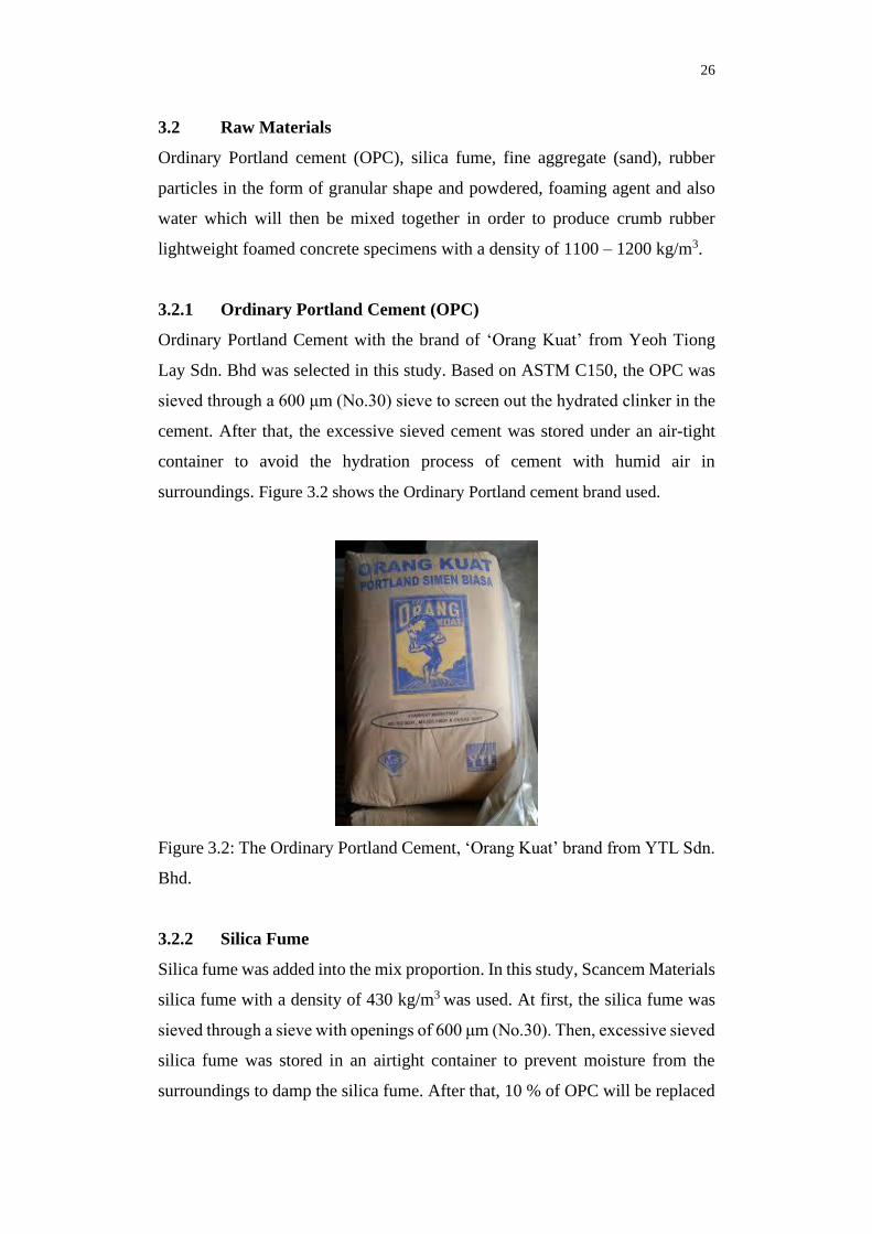
3.2.1 Ordinary Portland Cement (OPC)
Ordinary Portland Cement with the brand of ‘Orang Kuat’ from Yeoh Tiong
Lay Sdn. Bhd was selected in this study. Based on ASTM C150, the OPC was
sieved through a 600 μm (No.30) sieve to screen out the hydrated clinker in the
cement. After that, the excessive sieved cement was stored under an air-tight
container to avoid the hydration process of cement with humid air in
surroundings. Figure 3.2 shows the Ordinary Portland cement brand used.
Figure 3.2: The Ordinary Portland Cement, ‘Orang Kuat’ brand from YTL Sdn.
Bhd.
3.2.2 Silica Fume
Silica fume was added into the mix proportion. In this study, Scancem Materials
silica fume with a density of 430 kg/m3 was used. At first, the silica fume was
sieved through a sieve with openings of 600 μm (No.30). Then, excessive sieved
silica fume was stored in an airtight container to prevent moisture from the
surroundings to damp the silica fume. After that, 10 % of OPC will be replaced
27
with silica fume in terms of mass (kilogram). For instance, 4 kg of cementitious
material contains 3.6 kg of OPC and 0.4 kg of silica fume. Figure 3.3 illustrates
the sieved silica fume of Scancem Materials.
Figure 3.3: Silica Fume from Scancem Materials.
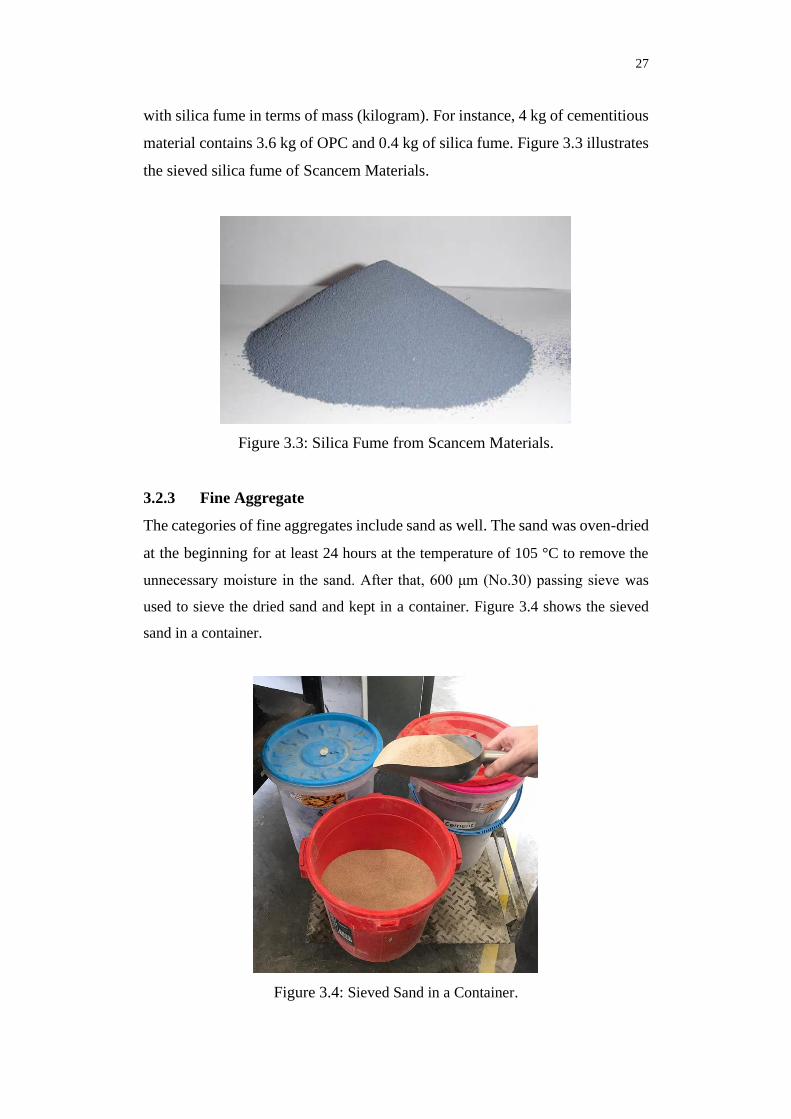
3.2.3 Fine Aggregate
The categories of fine aggregates include sand as well. The sand was oven-dried
at the beginning for at least 24 hours at the temperature of 105 °C to remove the
unnecessary moisture in the sand. After that, 600 μm (No.30) passing sieve was
used to sieve the dried sand and kept in a container. Figure 3.4 shows the sieved
sand in a container.
Figure 3.4: Sieved Sand in a Container.

28
3.2.4 Crumb Rubber
Crumb rubber was used in this study to replace the sand partially. There are two
different sizes of crumb rubber in this study, which are the granular and
powdered crumb rubbers. Granular crumb rubber particles were sieved between
the ranges of 0.075 mm - 4.75 mm (No.4 and No.200 sieve) sieve whereas
powdered crumb rubber comes in the size of 40 mesh. Figure 3.5 and 3.6
illustrate the crumb rubber for the laboratory work.
Figure 3.5: Granular Crumb Rubber Particles.
Figure 3.6: Powdered Crumb Rubber Particles.

29
3.2.5 Foaming Agent
In this study, SikaAER@ - 50/50 had been chosen to be used as the air-entraining
agent due to its strong air-entraining properties. Figure 3.7 shows the SikaAER@
- 50/50, a strong air-entraining admixture, which is also known as a foaming
agent to produce foam when mixed with water and pressurized in the foam
generator.
Figure 3.7: The Foaming Agent - SikaAER@ - 50/50.
The mixture of foaming agent and water into the foam generator under
the pressure of 0.5 MPa was used to produce foam with desired density. The
ratio of a foaming agent to water was around 1:20 and the density of the
produced foam was approximately 45 ± 5 kg/m3. After that, the stabilized foam
was induced and dispensed out through the nozzle. Figure 3.8 shows the foam
generator and Figure 3.9 illustrates the generated foam.

30
Figure 3.8: Foam Generator.
Figure 3.9: Generated Foam.

31
3.2.6 Water
Water is one of the most important components used to mix the concrete and for
water curing stage. Throughout this research, tap water was used. The negative
effect of cement hydration and the durability can be avoided by making sure the
pH value of water was normal and free from impurities.
3.3 Mould
Three types of concrete moulds were used in this research:
1. 100 mm x 100 mm x 100 mm cube for the compressive strength test.
2. 200 mm (H), diameter 100 mm cylinders for the splitting tensile strength
test, and
3. 40 mm x 40 mm x 160 mm prism for the flexural strength test.
Before using the moulds, the moulds were cleaned and checked to assure
that they are free from concrete residues from previous work. The pressure
cleaner was used to help in cleaning the moulds. After that, the moulds were
covered with a layer of oil before pouring the concrete into it to ease the work
of demoulding.
3.4 Mix Proportions
In this study, 16 sets of mix proportions of crumb rubber lightweight foamed
concrete and 1 controlled mix (CLFC - 0) were produced.
Firstly, the controlled mix did not contain either granular or powdered
crumb rubber particles. It is set as the reference for the other mix proportions.
Next, there were eight sets of granular crumb rubber lightweight foamed
concrete (GCLFC) while the remaining eight sets were powdered crumb rubber
lightweight foamed concrete (PCLFC). The proportion of granular and
powdered crumb rubber particles range from 10 % - 80 % with an interval of
10 % respectively.
Besides that, the water-cement ratio was fixed at 0.60 for each mix
proportion of the crumb rubber lightweight foamed concrete. The designations
of granular crumb rubber lightweight foamed concrete and powdered crumb

32
rubber lightweight foamed concrete is reported in Table 3.1 and Table 3.2
respectively.
Table 3.1: Granular Crumb Rubber Lightweight Foamed Concrete (GCLFC)
Design Mix.
Designation Replacement of Rubber
Particles (%)
Water/Cement
Ratio
GCLFC – 10 10 0.60
GCLFC – 20 20 0.60
GCLFC – 30 30 0.60
GCLFC – 40 40 0.60
GCLFC – 50 50 0.60
GCLFC – 60 60 0.60
GCLFC – 70 70 0.60
GCLFC – 80 80 0.60
Table 3.2: Powdered Crumb Rubber Lightweight Foamed Concrete (PCLFC)
Design Mix.
Designation Replacement of Rubber
Particles (%)
Water/Cement
Ratio
PCLFC – 10 10 0.60
PCLFC – 20 20 0.60
PCLFC – 30 30 0.60
PCLFC – 40 40 0.60
PCLFC – 50 50 0.60
PCLFC – 60 60 0.60
PCLFC – 70 70 0.60
PCLFC – 80 80 0.60

33
The mix proportioning begins with the selection of the unit weight of the
concrete (wet density), the cement content, and the water-cement ratio. Next,
the mix is proportioned by the method of absolute volumes. Silica fume was
used as a cementitious material which replaces 10 % of the cement by weight
and the W/C ratio was fixed at 0.6.
The partial replacement of sand in lightweight foamed concrete with
crumb rubber particles leads to a reduction of density due to its lower specific
gravity of crumb rubber (1150 kg/m3) compared to sand (2650 kg/m3). The
crumb rubber lightweight foamed concrete actual material density is reported in
Table 3.3. The density of all mixes should be equal, which is 1150 kg/m3.

34
Table 3.3: The Actual Density of Materials in Concrete Mixture for GCLFC and PCLFC.
Concrete Mixtures Cement
(kg/m3)
Silica Fume
(kg/m3)
Sand
(kg/m3)
Water
(kg/m3)
Crumb Rubber
(kg/m3)
Foam
(kg/m3)
Fresh
Density
(kg/m3) GCLFC PCLFC
CLFC- 0 392.66 43.63 436.29 261.78 0.00 0.00 15.64 1150.00
GCLFC- 10 PCLFC – 10 401.95 44.66 401.95 267.96 18.54 18.54 14.94 1150.00
GCLFC- 20 PCLFC – 20 411.68 45.74 365.94 274.45 37.97 37.97 14.21 1150.00
GCLFC- 30 PCLFC – 30 421.89 46.88 328.14 281.26 58.38 58.38 13.45 1150.00
GCLFC- 40 PCLFC – 40 432.63 48.07 288.42 288.42 79.81 79.81 12.65 1150.00
GCLFC- 50 PCLFC – 50 443.92 49.32 246.62 295.95 102.37 102.37 11.80 1150.00
GCLFC- 60 PCLFC – 60 455.83 50.65 202.59 303.88 126.14 126.14 10.91 1150.00
GCLFC- 70 PCLFC – 70 468.38 52.04 156.13 312.26 151.22 151.22 9.97 1150.00
GCLFC- 80 PCLFC – 80 481.65 53.52 107.03 321.10 177.72 177.72 8.98 1150.00

35
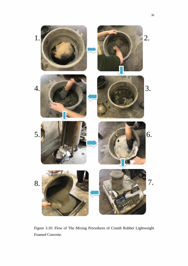
3.5 Mixing Procedure
Generally, the steps to produce the crumb rubber lightweight foamed concrete
are almost similar to the steps in producing the normal concrete. The only
difference is the addition of the foaming agent and the crumb rubber particles in
concrete. The mixing procedures for preparing CLFC - 0, GCLFC and PCLFC
were similar except for the replacement percentage of sand and crumb rubber.
First of all, a ball mixer was prepared and the dry mix was carried out in
the mixer, which includes cement, silica fume, sand and crumb rubber particles.
The materials were weighted accordingly to the mix proportion before they are
mixed thoroughly in the mixer. Once the mixture was evenly mixed, water was
weighted accurately and added gently into the mixing bowl until it achieved the
desired water-cement ratio. The foam was produced in the foam generator and
the volume of a foaming agent to water ratio was 1:20. Then, the foaming agent
was added into the wet mixture until it attained the desired density of 1100 -
1200 kg/m3.
After mixing, the fresh crumb rubber lightweight foamed concrete was
poured, spread evenly and compacted in the prepared moulds.
36
Figure 3.10: Flow of The Mixing Procedures of Crumb Rubber Lightweight
Foamed Concrete.
1.
4.
2.
3.
6. 5.
7. 8.

37
3.6 Casting
After achieving the desired density for the concrete, the wet mixture was cast
into three different concrete moulds. The first mould was the cube mould for
compressive strength test with a dimension of 100 mm x 100 mm x 100 mm,
the second mould was the 200 mm (H) x diameter 100 mm cylindrical mould
for splitting tensile strength test and lastly, 40 mm x 40 mm x 160 mm prism
mould for flexural strength test. Then, the excessive fresh concrete at the top
surface of the mould was removed and levelled after 15 minutes of casting. Next,
the fresh concrete was left for 24 hours to set and harden before it was removed
from its mould. After that, the concrete was incubated into the water tank for
curing purposes.
Figure 3.11: Casting of Concrete.
3.7 Curing
The concrete samples were cured in the water tank to enhance the
hydration process of the samples. An optimum duration of 28 days was required
for the concrete to undergo a chemical reaction with water so that an ideal
concrete strength could be achieved. The temperature of water in the water tank

38
for curing purposes was controlled within the range of 25 to 28 oC. The
specimens were cured for 28 days. Figure 3.12 shows the specimens to be cured
in the water tank.
Figure 3.12: Curing Process of Concrete Specimens.
3.7.1 Density Test
The fresh density test was carried out in accordance with ASTM C138 by using
a container (1 litre). Figure 3.13 shows the wet density test. The weight of the
container was weighted by using the electronic weighing machine.
Figure 3.13: Fresh Density Test of Fresh Concrete.

39
First, the container was completely filled with fresh concrete. Next, the
side of the container was slightly tapped for consolidation purposes. After filling
the container, the excess fresh concrete at the top of the container was wiped out
to ensure the surface was flat. Then, the container containing the fresh concrete
was weighted and the density was recorded. The steps were repeated to obtain
the average result. The fresh density was calculated based on the equation (3.1).
𝐷𝑒𝑛𝑠𝑖𝑡𝑦 = 𝑀𝑎𝑠𝑠
𝑉𝑜𝑙𝑢𝑚𝑒 (3.1)
3.8 Hardened Concrete Test
After curing the concrete specimens for 28 days, the following tests were carried
out to determine the mechanical properties of the crumb rubber lightweight
foamed concrete. Before that, all the specimens were dried in the oven so that
the moisture of the concrete surface can be removed.
3.8.1 Compressive Strength
The compressive strength test was carried out based on BS EN 12390-3 (2002),
by testing cube specimens with dimension 100 mm x 100 mm x 100 mm. The
compression machine (AD 300/EL Digital Readout 3000 kN) was used to carry
out the concrete compression test. Figure 3.14 illustrates the compression
machine, and the position of the concrete cube before the force is applied.

40
Figure 3.14: Compression Test in Compression Machine AD 300/EL Digital
Readout 3000 kN.
The concrete cubes were measured and recorded before the
commencement of the compressive strength test. The concrete cubes were then
placed on the centre of the compression machine. A constant axial load of 0.2
kN/s was applied on the concrete until the fracture point. The optimum reading
from the machine was then recorded. After that, the steps were repeated to
obtain the results for the next two concrete cubes. An average value was
obtained for the calculation.
Equation (3.2) demonstrates the calculation of compressive strength for
the crumb rubber lightweight foamed concrete.
𝐶𝑜𝑚𝑝𝑟𝑒𝑠𝑠𝑖𝑣𝑒 𝑆𝑡𝑟𝑒𝑛𝑔𝑡ℎ, 𝐹 = 𝐿𝑜𝑎𝑑 (𝑃)
𝐶𝑟𝑜𝑠𝑠−𝑆𝑒𝑐𝑡𝑖𝑜𝑛𝑎𝑙 𝐴𝑟𝑒𝑎(𝐴) (3.2)
where
F = Compressive strength, MPa
P = load applied by the machine, N
A = cross-section area of the concrete cube, m2

41
Figure 3.15: The Machine Setup for the Rate of Compressive Strength.
3.8.2 Splitting Tensile Strength
The splitting tensile test was applied in this study to obtain the tensile strengths
of the concrete. The steps to carry out the test were almost the same as the
previous compression test, except this time a cylindrical specimen was used
instead of a cube specimen. After 28 days of curing, the specimens were
removed from the water tank and oven-dried. A diametrical line at both ends of
the specimen was drawn to ensure that they are on the same axial axis.
Figure 3.16 shows the placing of a cylindrical specimen for splitting
tensile test. Before carrying out the test, the dimension and the weight of the
specimens were recorded. Two plywood bearing strips were placed at the top
and bottom surface of the specimen to ensure an even distribution of loading.
Figure 3.16: The Placing of Cylindrical Specimen for Splitting Tensile Strength
Test.

42
After that, load was applied continuously at a rate of 0.2 kN/s until
cracking occur. The breaking load (P) was then recorded. To calculate the
splitting tensile strength of the specimen, equation 3.3 was used:
𝑇 = 2P
π LD (3.3)
where
T = splitting tensile strength, MPa
P= maximum applied load indicated by the testing machine, N
D= diameter of the specimen, m
L= length of the specimen, m
Figure 3.17: Illustration of The Tensile Test on Concrete (Hamakareem, 2016).
3.8.3 Flexural Strength
The flexural strength is also known as the modulus of rupture. In this study,
prism specimens were used to carry out the test. The flexural test was done based
on the guidelines of ASTM C496 standard. Figure 3.18 shows the size of the
mould (40 mm x 40 mm x 160 mm) of the concrete prism specimen to be tested.

43
Figure 3.18: Prism Mould.
Before the test was carried out, the prism specimens were oven-dried for
24 hours. Then, it was horizontally placed on the machine based on Figure 3.19.
A continuous loading was applied at the middle of the prism specimen at a rate
of 0.2 kN/s until the failure point occurred. After that, the test was repeated for
the other two specimens and the results were averaged and recorded.
Figure 3.19: The Concrete Set Up on the Flexural Machine.

44
To calculate the flexural strength of the prism specimen, Equation (3.4) was
used:
R = 3PL/2bd2 (3.4)
where
Load and Flexural Strength
• P = Maximum Load Applied Indicated by Compression Machine (N)
• R = Flexural Strength (MPa)
Dimensions
• L = Maximum Span Length (mm)
• b = Average Specimen Width (mm)
• d = Average Specimen Depth (mm)
3.9 Summary
Overall, the procedures were separated into two stages. The first stage was the
casting of crumb rubber lightweight foamed concrete in various moulds, which
are the cube, cylindrical and prism moulds. Firstly, a sieve analysis was
conducted to analyse the properties of the materials. Next, crumb rubber
lightweight foamed concrete specimens were produced by adding the foaming
agent until the concrete had achieved the desired density of 1100 to 1200 kg/m3.
A total of 17 different mix proportions of crumb rubber lightweight foamed
concrete were produced with different percentages of crumb rubber replacement.
They are 10 %, 20 %, 30 %, 40 %, 50 %, 60 %, 70 % and 80 % for both granular
and powdered crumb rubber lightweight foamed concrete. After that, fresh
density measurements were conducted to test the fresh concrete properties.
The second stage was the testing stage, where compressive strength test,
flexural strength test and splitting tensile strength test were carried out to test
the crumb rubber lightweight foamed concrete after 28 days of curing. After that,
the results and data were collected for the comparison of the mechanical strength
of granular and powdered crumb rubber lightweight foamed concrete.

45
CHAPTER 4
4 RESULTS AND DISCUSSION
4.1 Introduction
This chapter discusses the outcome of this study, which is essential to justify the
feasibility of using crumb rubber particles in lightweight foamed concrete to
further increase the mechanical strength. Three main mechanical strength tests
were carried out, namely the compressive strength test, flexural strength test and
the splitting tensile strength test. In addition, the comparison of mechanical
strength between two different sizes of crumb rubber particles in concrete, that
are granular (GCLFC) and powdered (PCLFC) crumb rubber lightweight
foamed concrete was recorded and presented. All concrete samples were cured
in water for 28 days before testing. Finally, the interpretation of result data was
discussed as well.
4.2 Mechanical Properties Test
Three main tests were conducted in this study to obtain the mechanical
properties of the crumb rubber lightweight foamed concrete. The tests include
the flexural strength test, compressive strength test and the splitting tensile
strength test. A total of 17 sets of fresh concrete mixtures were produced with
different percentages of granular and powdered crumb rubber replacement
ranging from 0% to 80% respectively. The average value was calculated to
achieve the accuracy and consistency of the result.
Hypothetically, the presence of crumb rubber itself in concrete will
consequently diminish the mechanical strength as the cement paste and the
crumb rubber particle boundaries adhesion forces between them are gradually
reducing, causing an increase in the volume of the interface transition zone (Sofi,
2018). However, by introducing crumb rubber in lightweight foamed concrete
could enhance the strength in terms of mechanical properties. The reasons for
this phenomenon will be discussed in the following subtopics.

46
4.2.1 Compressive Strength Test
The compressive strength test is one of the most important tests in the
construction industry to evaluate the quality and grading of concrete. A total of
51 concrete cube samples with a dimension of (100 x 100 x 100) mm were cast
in this study for compressive strength testing. The 51 cube samples consist of
both granular (GCLFC) and powdered (PCLFC) crumb rubber lightweight
foamed concrete with different percentages of crumb rubber replacement. The
compressive strength was obtained by taking the maximum load (P) of a cube
divided by the surface area (A) of contact. Three cube samples were tested for
each set. Table 4.1 and 4.2 show the result of the compressive strength test of
GCLFC and PCLFC while Figure 4.1 and 4.2 illustrate the bar chart of the
averaged compressive strength for both GCLFC and PCLFC.

47
Table 4.1: The Result of Compressive Strength Test of GCLFC.
Compressive Strength (MPa)
A B C Avg.
CLFC - 0 2.670 2.580 2.720 2.657
GCLFC - 10 2.770 2.710 2.850 2.777
GCLFC - 20 3.190 2.650 2.950 2.930
GCLFC - 30 2.600 2.670 2.710 2.660
GCLFC - 40 2.470 2.520 2.600 2.530
GCLFC - 50 2.250 2.390 2.470 2.440
GCLFC - 60 2.410 2.360 2.540 2.437
GCLFC - 70 2.220 2.650 2.180 2.350
GCLFC - 80 1.970 2.470 2.390 2.277
Figure 4.1: Compressive Strength versus Percentage of Granular Crumb Rubber
Proportion – GCLFC.
Based on Figure 4.1, it shows that the compressive strength increases at
the first 20 % of the bar chart and then decreases dramatically after that. The
compressive strength of GCLFC is at its peak at 20 % of granular crumb rubber
proportion with an increment of 10.27 % compared to the controlled mix, which
2.657
2.777
2.930
2.660
2.530
2.440 2.437
2.350
2.277
2.0
2.2
2.4
2.6
2.8
3.0
0 10 20 30 40 50 60 70 80
Com
pre
ssiv
e S
tren
gth
(M
Pa)
Crumb Rubber Proportion (%)
Designation
Specimen

48
is 2.930 MPa. After that, it falls to 2.277 MPa at 80 % of crumb rubber
proportion. The reason for such decrease is due to the lack of proper bonding
between cement paste and crumb rubber particles, as compared to natural
aggregate (sand) and cement paste. As a result, the non-uniform distribution of
stresses applied could lead to the formation of cracks (Sofi, 2018).
Table 4.2: The Result of Compressive Strength Test of PCLFC.
Compressive Strength (MPa)
A B C Avg.
CLFC - 0 2.620 2.850 2.880 2.657
PCLFC - 10 2.890 2.930 2.730 2.783
PCLFC - 20 2.990 2.880 2.710 2.850
PCLFC - 30 2.910 2.750 2.550 2.860
PCLFC - 40 2.740 2.850 2.740 2.737
PCLFC - 50 3.380 3.510 2.990 2.740
PCLFC - 60 3.390 3.720 3.560 3.293
PCLFC - 70 3.180 4.080 3.140 3.557
PCLFC - 80 3.180 4.080 3.140 3.467
Designation
Specimen

49
Figure 4.2 : Compressive Strength versus The Percentage of Crumb Rubber –
PCLFC.
The bar chart for PCLFC depicts that the compressive strength of
PCLFC fluctuated and generally rises throughout the chart. It increases at the
beginning but there is a significant diminution in the strength when it hits 40 %
of powdered crumb rubber proportion. This phenomenon might have happened
due to the uneven distribution of foam and crumb rubber during concrete mixing,
which forms an unstable mix with high voids and porosity (Johnson, 2018).
Concrete with higher voids is more permeable to soluble elements and water.
Hence, a slight reduction in strength and durability is expected in this kind of
situation. However, it continues to rise after 50 % of crumb rubber proportion
and reaches its highest compressive strength at 70 % with the compressive
strength result of 3.557 MPa. Overall, the obtained results have shown that the
PCLFC, which contains a portion of powdered crumb rubber particles has better
compressive strength as it increases 33.87 % compared to the controlled mix,
CLFC – 0.
Figure 4.3 illustrates the comparison of the average compressive
strength between both GCLFC and PCLFC with different percentages of crumb
rubber proportion. The inclusion of crumb rubber that acts as a filler or an
2.657
2.7832.850 2.860
2.737 2.740
3.293
3.5573.467
2.0
2.2
2.4
2.6
2.8
3.0
3.2
3.4
3.6
3.8
0 10 20 30 40 50 60 70 80
Co
mp
ress
ive
Str
eng
th (
MP
a)
Crumb Rubber Proportion (%)

50
additive in lightweight foamed concrete had shown a partial improvement in the
compressive strength for both concretes.
By comparing the graphs from Figure 4.3, it is apparent that both graphs
consist of an upward trend on the compressive strength development but for the
GCLFC, it declines right after it reaches its peak at 20 % (2.930 MPa) of crumb
rubber proportion, earlier than the PCLFC which continues to increase until 70
% with a peak value of 3.557 MPa.
Figure 4.3 : The Relationship between The Compressive Strength of GCLFC
and PCLFC.
Besides that, the PCLFC with the particle size of 40 mesh has bigger
effects in the increment of the compressive strength compared to the GCLFC
with the particle size of 1 to 40 mm. This could be explained by looking at the
compressive strength of PCLFC, which has further improved by 33.87 % at 70
% of crumb rubber proportion. Cement mortar consists of different sizes of
pores inside and the finer size of crumb rubber particles may fill the pores and
improve the density of concrete which caused the compressive strength to
increase.
For GCLFC, the compressive strength has improved by 4.52 % to
10.28 % during the first 10 and 20 % of crumb rubber proportion. However,
y = -7E-05x2 - 0.0013x + 2.7662
R² = 0.7862
y = 0.0002x2 - 0.004x + 2.7412
R² = 0.8027
2.0
2.2
2.4
2.6
2.8
3.0
3.2
3.4
3.6
3.8
0 20 40 60 80
Co
mp
ress
ive
stre
ng
th (
MP
a)
Crumb Rubber Proportion (%)
GCLFC
PCLFC
Poly.
(GCLFC)
Poly.
(PCLFC)

51
beyond the crumb rubber proportion of 20 %, the strength started reducing
tremendously to 2.277 MPa, a reduction percentage of 14.3 %. This observation
can be explained by the excessive amount of crumb rubber with a hydrophobic
property which in turn creates the additional number of voids into the concrete
causing a poor bonding between the crumb rubber particles and the cement paste
(Yong, 2016). Besides, rubber particles generally contain relatively low strength
and as the proportion of crumb rubber increases, the properties of rubber would
eventually dominate the properties of concrete which results in the loss of
strength (Pelisser, et al., 2011). Moreover, the development of micro-crack
attributed by the high content of crumb rubber particles will affect the
compressive strength of the GCLFC (Abdullah, et al., 2017).
4.2.2 Splitting Tensile Strength
The splitting tensile strength is one of the most useful and fundamental
properties which could determine the performance and size of cracking in a
concrete structure. Concrete is weak in tension due to its brittle nature and it
cannot resist tension directly. Moreover, cracks will develop when tensile forces
applied exceed the tensile strength of concrete. A total of 51 concrete cylindrical
samples with dimension (H = 200mm, d = 100mm) were cast in this study for
splitting tensile strength test. These cylindrical samples consist of different
percentages of crumb rubber replacement for both granular and powdered
crumb rubbers. Table 4.3 shows the result of the splitting tensile strength test of
GCLFC and the average splitting tensile strength for GCLFC with different
percentages of granular crumb rubber replacement is illustrated in Figure 4.4.

52
Table 4.3: The Result of Splitting Tensile Strength Test of GCLFC.
Splitting Tensile Strength (MPa)
A B C Avg.
CLFC - 0 0.353 0.331 0.299 0.328
GCLFC - 10 0.344 0.360 0.321 0.342
GCLFC - 20 0.341 0.401 0.455 0.399
GCLFC - 30 0.398 0.376 0.369 0.381
GCLFC - 40 0.315 0.306 0.442 0.354
GCLFC - 50 0.321 0.325 0.293 0.313
GCLFC - 60 0.341 0.344 0.248 0.311
GCLFC - 70 0.280 0.245 0.245 0.257
GCLFC - 80 0.226 0.251 0.226 0.234
Figure 4.4: Splitting Tensile Strength versus The Percentage of Crumb Rubber
– GCLFC.
Similar to the trend observed in compressive strength of GCLFC, the bar
chart of splitting tensile strength increases at the first 20 % of crumb rubber
replacement and then declines vigorously after that. The reason behind this
increase is inflicted by the improvement of adhesion between crumb rubber
0.3280.342
0.399
0.381
0.354
0.313 0.311
0.257
0.234
0.20
0.25
0.30
0.35
0.40
0.45
0 10 20 30 40 50 60 70 80
Sp
litt
ing
Ten
sile
Str
eng
th (
MP
a)
Crumb Rubber Proportion (%)
Designation
Specimen

53
particles with cement paste compared to the adhesion of normal aggregate (sand)
with the cement matrix. The irregular shape and rough surface of crumb rubber
particles with uncountable voids have the ability to effectively absorb the tensile
stresses and hence increasing the splitting tensile strength (Grinys, et al., 2012).
However, a significant drop in splitting tensile strength would occur
once the crumb rubber particles exceed its maximum amount of replacement,
which is from 30 % onwards. The splitting tensile strength of GCLFC is at its
peak during 20 % of granular crumb rubber replacement, with a result of 0.399
MPa and it falls to 0.234 MPa at 80 %.
On the other hand, Figure 4.5 shows the average splitting tensile strength
of PCLFC with different percentages of powdered crumb rubber replacement.
The splitting tensile strength for PCLFC has shown a rather steady strength
growth starting from 20 % to 70 % of crumb rubber proportion. As the
percentage of powdered crumb rubber proportion increases, the splitting tensile
strength increases. The highest reading for the splitting tensile strength for
PCLFC is 0.533 MPa at 70 % of crumb rubber proportion, with a total increment
of 62.5 %. Although the trend is similar to the compressive strength of PCLFC,
the previous graph has a slight dip at 40 % of crumb rubber proportion. Overall,
the results have implied that the powdered crumb rubber particles are effective
in improving the splitting tensile strength of lightweight foamed concrete
compared to the controlled mix, CLFC – 0 with only 0.328 MPa in splitting
tensile strength. The result of the splitting tensile strength test for PCLFC is
reported in Table 4.4.

54
Table 4.4: The Result of Splitting Tensile Strength Test of PCLFC.
Splitting Tensile Strength (MPa)
A B C Avg.
CLFC - 0 0.353 0.331 0.299 0.328
PCLFC - 10 0.360 0.315 0.334 0.336
PCLFC - 20 0.293 0.334 0.296 0.308
PCLFC - 30 0.321 0.360 0.331 0.337
PCLFC - 40 0.388 0.411 0.407 0.402
PCLFC - 50 0.385 0.388 0.474 0.416
PCLFC - 60 0.487 0.503 0.411 0.467
PCLFC - 70 0.493 0.567 0.538 0.533
PCLFC - 80 0.465 0.417 0.430 0.437
Figure 4.5: Splitting Tensile Strength versus The Percentage of Crumb Rubber
-PCLFC.
Figure 4.6 compares the splitting tensile strength of the GCLFC and
PCLFC. The presence of crumb rubber in lightweight foamed concrete has a
different outcome in both GCLFC and PCLFC. The particle size of crumb
rubber matters in terms of splitting tensile strength. GCLFC shows a declining
0.328 0.3360.308
0.337
0.402 0.416
0.467
0.533
0.437
0.00
0.10
0.20
0.30
0.40
0.50
0.60
0 10 20 30 40 50 60 70 80
Sp
litt
ing
Ten
sile
Str
eng
th (
MP
a)
Crumb Rubber Proportion (%)
Designation
Specimen

55
curve while PCLFC shows a steady increase in the splitting tensile strength. For
GCLFC, the results reduce ranging from 4.57 % to 28.70 % as compared to the
CLFC – 0, whereas for PCLFC, it shows a continuous increment of 2.44 % to
62.50 %.
Figure 4.6: The Relationship between The Splitting Tensile Strength of GCLFC
and PCLFC.
Crumb rubber is a soft material where it could act as a barrier to prevent
concrete from crack growth (Sofi, 2018). Hence, the lightweight foamed
concrete containing crumb rubber particles should have higher tensile strength
compared to the controlled mix, CLFC – 0. However, for GCLFC, the results
show an opposite hypothesis. This behaviour could be due to the weak bonding
of the interface zone between the cement paste and crumb rubber particles which
accelerates the breakdown of the concrete (Taha, et al., 2008).
Compared to the previous compressive strength graph, this graph shows
a more consistent result. One notable finding is that during the testing stage, the
size and number of cracks appeared on the GCLFC was larger than the ones on
PCLFC. This is due to the bonding between the crumb rubber particles and the
cement paste of GCLFC, which is not as strong as the bonding of powdered
y = -5E-05x2 + 0.0026x + 0.3357
R² = 0.8899
y = 5E-06x2 + 0.002x + 0.3058
R² = 0.747
0.20
0.25
0.30
0.35
0.40
0.45
0.50
0.55
0 20 40 60 80
Sp
litt
ing
Ten
sile
Str
eng
th (
MP
a)
Crumb Rubber Proportion (%)
GCLFC
PCLFC
Poly.
(GCLFC)
Poly.
(PCLFC)

56
crumb rubber particles and the cement paste. Figure 4.7 and 4.8 shows the
concrete failure of GCLFC and PCLFC for splitting tensile test.
Figure 4.7: Concrete Failure of GCLFC.
Figure 4.8: Concrete Failure of PCLFC.

57
To generalise the results of the crumb rubber lightweight foamed
concrete for splitting tensile strength, it may be noted that there is a slight
increase in the splitting tensile strength for GCLFC when a small amount of
crumb rubber particles are introduced (Eltayeb, et al., 2020). Finer (powdered)
crumb rubber particles are better with the ability of void filling. With a larger
surface area of the fine (powdered) crumb rubber particles, the overall surface
area of the concrete paste was able to increase. Therefore, a more evenly mixture
was produced, resulting in a higher splitting tensile strength. Moreover, finer
crumb rubber generates more effective packing structures especially in the zone
of interfacial of the lightweight foamed concrete, making it more homogenous
hence increases the tensile strength of the concrete (Abdullah, et al., 2017).
4.2.3 Flexural Strength
The flexural strength of concrete can be defined as the maximum bending stress
that concrete can sustain before yielding. It can be obtained by using a technique
called three-point flexural test. When a three-point load is applied to the centre
of a concrete prism, it will experience tension at the bottom and compression at
the top simultaneously. The elongation action caused by the bending would
result in the failure (break) of the prism when it cannot sustain the tension forces.
Hence, cracks would occur at the bottom. A total of 51 concrete prism samples
with dimension (40mm x 40mm x 160mm) were cast in this study for the
flexural strength test. The flexural strength of GCLFC and PCLFC are averaged
and reported in Figure 4.9 and 4.10, respectively.

58
Table 4.5: The Result of Flexural Strength Test of GCLFC.
Flexural Strength (MPa)
A B C Avg.
CLFC - 0 2.221 2.191 2.138 2.183
GCLFC - 10 2.130 2.367 - 2.248
GCLFC - 20 1.760 1.755 1.617 1.710
GCLFC - 30 1.714 1.766 2.029 1.837
GCLFC - 40 0.911 0.822 1.214 0.982
GCLFC - 50 0.875 1.237 1.493 1.202
GCLFC - 60 1.318 1.164 1.033 1.172
GCLFC - 70 1.003 1.020 1.397 1.140
GCLFC - 80 1.079 0.981 0.861 0.974
Figure 4.9: Flexural Strength versus The Percentage of Crumb Rubber –
GCLFC.
The gradual reduction in the flexural strength can be explicitly seen from
Figure 4.9 as the percentage of crumb rubber replacement increases. At 10 % of
crumb rubber proportion records the highest flexural strength (2.248 MPa) of
GCFLC, and beyond that, it starts reducing to 0.974 MPa at 80 %. The greatest
2.183 2.248
1.7101.837
0.982
1.202 1.172 1.1400.974
0.0
0.5
1.0
1.5
2.0
2.5
0 10 20 30 40 50 60 70 80
Fle
xu
ral
Str
eng
th (
MP
a)
Crumb Rubber Proportion (%)
Designation
Specimen

59
reduction in flexural strength occurs at 40 % of crumb rubber replacement, with
a 55 % strength reduction compared to the controlled mix, CLFC – 0 (0.982
MPa).
During the flexural test, the specimens without the crumb rubber
particles (CLFC – 0) split into two pieces shortly after cracking and it exhibited
brittle failure. However, for the specimens containing crumb rubber particles
showed deformation and it did not disintegrate completely.
Furthermore, the bar chart for PCLFC is rather unusual as there are two
peaks. The first peak falls at 40 % (2.329 MPa) while the second peak is at 80 %
(2.829 MPa) of crumb rubber proportion. At the beginning of the bar chart (0 %
to 40 %), the flexural strength of PCLFC decreases remarkably, but at 40 % of
crumb rubber replacement, unexpectedly, the flexural strength soars to 2.329
MPa and further reduces over to 1.762 MPa at 50 %. It should be noted that the
smaller the size of the crumb rubber particles used in concrete, the lesser the
loss of strength (Su, et al., 2015). This could be explained due to the increased
compactness of concrete by the filler effect of the finer crumb rubber particles,
which leads to the reduction of the stress singularity at the internal voids. As a
result, the likelihood of concrete fracture would be reduced.
Table 4.6: The Result of Flexural Strength Test of PCLFC.
Flexural Strength (MPa)
A B C Avg.
CLFC - 0 2.221 2.191 2.138 2.183
PCLFC - 10 2.049 2.310 2.127 2.162
PCLFC - 20 2.104 1.874 1.988 1.989
PCLFC - 30 1.938 1.835 1.554 1.776
PCLFC - 40 2.521 2.012 2.455 2.329
PCLFC - 50 1.876 1.714 1.695 1.762
PCLFC - 60 1.928 1.811 1.522 1.754
PCLFC - 70 1.752 1.793 1.969 1.838
PCLFC - 80 3.058 3.111 2.317 2.829
Designation
Specimen

60
Figure 4.10: Flexural Strength versus The Percentage of Crumb Rubber –
PCLFC.
Figure 4.11 illustrates the relationship between the flexural strength of
both GCLFC and PCLFC at 0% to 80% of crumb rubber proportion. Based on
the graph, PCLFC shows an overall higher flexural strength compared to
GCLFC. PCLFC has achieved a maximum flexural strength of 2.829 MPa, an
increment of 29.6 % compared to the controlled mix, CLFC – 0. Besides, as
expected, the trend for PCLFC is an upward curve while GCLFC exhibits a
downward curve.
2.183 2.1621.989
1.776
2.329
1.762 1.7541.838
2.829
0.0
0.5
1.0
1.5
2.0
2.5
3.0
0 10 20 30 40 50 60 70 80
Fle
xu
ral
Str
ength
(M
Pa)
Crumb Rubber Proportion (%)

61
Figure 4.11: The Relationship between The Flexural Strength of GCLFC and
PCLFC.
For the GCLFC, the justification for the decreasing flexural strength is
primarily due to the bonding between the granular crumb rubber particles and
the cement paste which is simply inadequate (Lim, et al., 2019). Moreover, the
diminution of flexural strength is also mainly inflicted by the shape and size of
the crumb rubber particles (Gupta, et al., 2014). During the loading phase, the
cracks propagation will be accelerated by the smooth texture of crumb rubber
particles; hence the reduction of the overall resistance against the applied force
will occur.
On the other hand, the increasing flexural strength of PCLFC could be
explained by the effective packing structures produced by the powdered crumb
rubber especially in the zone of interfacial as well as the strong bonding between
the cement paste and the crumb rubbers that helped in the bridging of cracks
and delayed the failure of the PCLFC (Grinys, et al., 2012).
y = 0.0002x2 - 0.0318x + 2.3321
R² = 0.8461
y = 0.0003x2 - 0.0256x + 2.3139
R² = 0.3807
0.5
1.0
1.5
2.0
2.5
3.0
0 20 40 60 80
Fle
xu
ral
Str
ength
(M
Pa)
Crumb Rubber Proportion (%)
GCLFC
PCLFC
Poly.
(GCLFC)
Poly.
(PCLFC)

62
4.3 Summary
To summarise, the results obtained from the mechanical tests were analysed,
tabulated and discussed. It was concluded that the presence of crumb rubber in
lightweight foamed concrete is not necessarily detrimental. The results of this
study indicate that using both granular and powdered crumb rubber in
lightweight foamed concrete has a potential improvement in the mechanical
strength except that both have different optimum crumb rubber proportion.
Overall, the results have shown a similar trend for both GCLFC and PCLFC in
all 3 tests.
The mechanical strength of PCLFC increases as the crumb rubber
proportion increases and the ideal percentage of powdered crumb rubber
proportion is at 70 - 80 %. This is because finer (powdered) crumb rubber
particles are good with the ability of void filling and generate more effective
packing structures, especially in the zone of interfacial of the lightweight
foamed concrete. However, for GCLFC, the mechanical strength only rises at
10 – 20 % of crumb rubber proportion. Beyond 20 %, the GCLFC will undergo
a reduction in mechanical strength due to the lack of proper bonding between
cement paste and crumb rubber particles.
Figure 4.12 shows the correlation of the combined mechanical strength
test results between both GCLFC and PCLFC. The maximum compressive
strength is 2.930 MPa (GCLFC) and 3.557 MPa (PCLFC), maximum flexural
strength is 2.248 MPa (GCLFC) and 2.829 MPa (PCLFC) while the maximum
splitting tensile strength is only 0.399 MPa (GCLFC) and 0.533 MPa (PCLFC).
Table 4.7 summarises the increment percentage of the mechanical strength
between the controlled mix, CLFC – 0 and both types of crumb rubber
lightweight foamed concrete.

63
Figure 4.12: Comparison of The Mechanical Strength Results for GCLFC and
PCLFC.
Table 4.7: The Percentage Increment of The Mechanical Strength between The
Controlled Mix, GCLFC and PCLFC.
Increment
Percentage
of GCLFC
(%)
Optimal
Percentage
of Crumb
Rubber
Proportion
Increment
Percentage
of PCLFC
(%)
Optimal
Percentage
of Crumb
Rubber
Proportion
Compressive
Strength
10.27 20 % 33.87 70 %
Splitting
Tensile
Strength
21.65 20 % 62.50 70 %
Flexural
Strength
2.97 10 % 29.59 80 %
2.930
0.399
2.248
3.557
0.533
2.829
0.0
0.5
1.0
1.5
2.0
2.5
3.0
3.5
4.0
Compressive
Strength
Splitting Tensile
Strength
Flexural Strength
Res
ult
(M
Pa)
Strength Test
GCLFC
PCLFC
Strength
Increment
Mechanical
Strength

64
CHAPTER 5
5 CONCLUSIONS AND RECOMMENDATIONS
5.1 Conclusions
Based on the analysis of results and laboratory testing, several conclusions can
be drawn.
The utilization of either granular or powdered crumb rubber in
lightweight foamed concrete could affect the mechanical properties. By
replacing a partial mass of sand with granular crumb rubber, there is a potential
improvement in the mechanical strength, but it will also lead to the reduction of
mechanical strength as the percentage of rubber increases. From the previous
chapter, the compressive strength for GCLFC was reported, which rises till 20 %
of crumb rubber proportion with a value of 2.930 MPa, an increment of 10.27 %
compared to the controlled mix, CLFC - 0. However, beyond 20 %, the
compressive strength of GCLFC starts reducing and reduced by 4.8 % to 14.3 %.
Same goes to the splitting tensile strength for GCLFC, the optimum percentage
of the crumb rubber proportion is at 20 % (0.399 MPa), with a strength
increment of 21.65 %. After that, it starts decreasing by 4.57 % to 28.7 % at 30 %
to 80 % of crumb rubber proportion. As for the flexural strength for GCLFC,
the optimum crumb rubber proportion falls at 10 % (2.248 MPa). Compared to
the CLFC – 0, there is only 2.97 % in the increment of flexural strength. Then,
the strength continues diminishing till 80 % of crumb rubber proportion by
15.85 % to 55.4 %.
On the other hand, by replacing a part of sand with powdered crumb
rubber leads to the enhancement of strength as the percentage of rubber
increases. The PCLFC has shown that the compressive strength could increase
by 3.01 % to 33.87 % compared to the CLFC - 0. The optimum crumb rubber
proportion percentage is at 70 % by achieving a maximum value of 3.557 MPa.
The trend of splitting tensile strength is also similar to the compressive strength
of PCLFC. The maximum splitting tensile strength is 0.533 MPa, which is at
70 % of crumb rubber proportion. An increment by 2.44 % to 62.5 % of splitting
tensile strength has been archived by PCLFC. Lastly, the optimum crumb rubber

65
percentage for PCLFC flexural strength is at 80 %. It has increased by 6.7 % to
29.59 % compared to the CLFC – 0 with a maximum value of 2.829.
In a nutshell, by comparing both granular and powdered crumb rubber
lightweight foamed concrete, a higher mechanical strength could be achieved
by the finer size (powdered) of the crumb rubber in lightweight foamed
concrete. As mentioned above, the increment of the mechanical strength for
PCLFC is higher compared to the GCLFC. The compressive strength of PCLFC
increased by 33.87 % while GCLFC only increased by 10.37 %. In addition, the
splitting tensile strength of PCLFC rose by 62.50 % while GCLFC only rose by
21.65 %. Finally, the flexural strength of PCLFC had an increment of 29.59 %
while GCLFC had only 2.97 % of increment. The objectives have been
achieved.
5.2 Recommendations for Future Work
Several recommendations and suggestions below could be taken into
consideration in order to improve and achieve more reliable and accurate results
for future study:
I. Study the effects of different percentages of crumb rubber on other
engineering properties such as sound insulation, thermal conductivity,
impact and water absorption instead of mechanical properties.
II. Investigate the long-term effects of the strength and workability of
lightweight foamed concrete, by including the use of chemical
admixture such as superplasticizer in the mix proportion for future study.
III. Adopt a broader range of crumb rubber sizes and shape on the
mechanical properties of lightweight foamed concrete instead of
comparing only two sizes.
IV. Study the effects on the mechanical properties of crumb rubber
lightweight foamed concrete by considering different proportions of
silica fume.

66
REFERENCES
Abdullah, S. R., Riwayat, A. I., Awal, A. A. and Hossain, M. Z., 2017. Effect
of Rubber Powdered Particle on the Strength of Foamed Concrete. International
Journal of GEOMATE, 13(38), pp. 129-134.
Aiello, M. and Leuzzi, F., 2010. Waste tyre rubberized concrete: Properties at
fresh and hardened state. Waste Management, 30(8-9), pp. 1696-1704.
ASTM C 496/C 496M – 04, 2011 Standard Test Method for Splitting Tensile
Strength of Cylindrical Concrete Specimens, Annual Book of ASTM Standards
Volume 04.02, pp. 1–5.
ASTM C1611: Standard test method for slump flow of self-consolidating
concrete. American Society of Testing and Materials.
ASTM C78/C78M, 2002. ASTM C78/C78M - 02 - Standard Test Method for
Flexural Strength of Concrete (Using Simple Beam with Third-Point Loading),
ASTM International, pp. 1–3. (Oon, Ooi, and Pot, 2020)
Atahan, A. O., and Yücel, A. Ö., 2012. Crumb rubber in concrete: Static and
dynamic evaluation. Construction and Building Materials,36, pp. 617-622.
Batayneh, M., Marie, I. and Asi, I., 2008. Promoting the use of crumb rubber
concrete in developing countries. Waste Management, 28(11), pp. 2171-2176.
Benazzouk, A., Douzane, O., Mezreb, K., Laidoudi, B., and Quéneudec, M.,
2008. Thermal conductivity of cement composites containing rubber waste
particles: Experimental study and modelling. Construction and Building
Materials,22(4), pp. 573-579.
Bing, C., Zhen, W. and Ning, L., 2012. Experimental Research on Properties of
High-Strength Foamed Concrete. Journal of Materials in Civil Engineering,
24(1).
Bravo, M. and Brito, J. d., 2012. Concrete made with used tyre aggregate:
durability-related performance. Journal of Cleaner Production, Volume 25, pp.
42-50.
British Standards Institution, 2002. Testing hardened concrete–Part 3:
Compressive strength of test specimens. London: BS EN 12390-3:2002.
BS EN 206, 2013. BSI Standards Publication Concrete — Specification,
performance, production and conformity, British Standard, (May), pp. 30.
BS1881,1983. Testing Concete (Part 116) - Method for determination of
compresive strength of concrete cubes, Bsi, (December), p. 11.

67
Eltayeb, E., Ma, X., Youssf, O. and Mills, J. E., 2020. Influence of rubber
particles on the properties of foam concrete. Journal of Building Engineering,
Volume 19, pp. 2352-2367.
Fattuhi, N. I. and Clark, L. A., 1996. Cement-based materials containing
shredded scrap truck tyre rubber. Construction and Building Materials, 10(4),
pp. 229-236.
Gafoori, N. and Diawara, H., 2007. Strength and Wear Resistance of Sand -
Replaced Silica Fume Concrete. ACI Materials Journal, 104(2), pp.206-214.
Ganjian, E., Khorami, M. and Maghsoudi, A. A., 2009. Scrap-tyre-rubber
replacement for aggregate and filler in concrete. Construction and Building
Materials, 23(5), pp. 1828-1836.
Grinys, A., Sivilevicius, H. and Dauksys, M., 2012. Tyre Rubber Additive
Effect on Concrete Mixture. Journal of Civil Engineering and Management,
Volume 18, pp. 393-401.
Hilal , A. A., 2011. Effect of Crumb Tyres Rubber on Some Properties of
Foamed Concrete. Anbar Journal for Engineering Sciences , 4(2).
Issa, C. A. and Salem, G., 2013. Utilization of recycled crumb rubber as fine
aggregates in concrete mix design. Construction and Building Materials,
Volume 42, pp. 48-52.
Kaloush, K. E., Way, G. B. and Zhu, H., 2005. Properties of Crumb Rubber
Concrete. Transportation Research Record: Journal of the Transportation
Research Board, Volume 1914, pp. 8-14.
Khaloo, A., Dehestani, M. and Rahmatabadi, P., 2008. Mechanical properties
of concrete containing a high volume of tyre–rubber particles. Waste
Management, 28(12), pp.2472-2482.
Kumar, S., 2006. Waste Tyre Management in Malaysia. Retrieved from
http://psasir.upm.edu.my/id/eprint/145/
Lv, J., Zhou, T., Du, Q., and Wu, H., 2015. Effects of rubber particles on
mechanical properties of lightweight aggregate concrete. Construction and
Building Materials, 91, pp. 145-149.
Mehta, P. K., 1986. Concrete, Structure, properties and Materials. Englewood
Cliffs: Science Engineering Medicine.
Md Noor, N., Yamamoto, D., Hamada, H. and Sagawa, Y., 2016. Crumb rubber
Concrete Durability Against Abrasion. MATEC Web of Conferences, 47,
pp.01006.

68
Mugahed Amran, Y. H., Farzadnia, N. and Abang Ali, A. A., 2015. Properties
and applications of foamed concrete; a review. Construction and Building
Materials, Volume 101, pp. 990-1005.
Neville, A. M. and Brooks, J. J., 1987. Concrete Technology. Second ed.
London: Pearson.
Paine, K. A., and Dhir, R. K., 2010. Research on new applications for granulated
rubber in concrete. Proceedings of the Institution of Civil Engineers -
Construction Materials,163(1), pp. 7-17.
Pelisser, F., Zavarise, N., Longo, T. A. and Bernardin, A. M., 2011. Concrete
made with recycled tire rubber: Effect of alkaline activation and silica. Journal
of Cleaner Production, Volume 19, pp. 757-763.
Pierce, C. E. and Blackwell, M. C., 2003. Potential of scrap tire rubber as
lightweight aggregate in flowable fill. Waste Management, 23(3), pp. 197-208.
Rashaad, A. M., 2015. A comprehensive overview about recycling rubber as
fine aggregate replacement in traditional cementitious materials. International
Journal of Sustainable Built Environment, 5(1), pp. 46-82.
Shetty, M. S., 2008. Concrete Technology Theory and Practice. Revised ed.
New Delhi: S. CHAND and COMPANY PVT. LTD..
Siddique, R, and Khan, M,I (2011). Supplementary Cementing Materials, Silica
fume. XVI Publishers, 288 P, ISBN:978- 3-642-17865-8.
Siddique, R., and Naik, T. R., 2004. Properties of concrete containing scrap-tyre
rubber – an overview. Waste Management,24(6),pp. 563-569.
Sivakumar, M., Poorani, M., Sudha, S. J. and Deepa, S., 2016. Influence of
Silica Fume on Mechanical Properties of Crumb Rubber Aggregate Concrete.
International Journal of Engineering Research and Technology (IJERT), 5(12).
Skripkiūnas, G., Grinys, A. and Cernius, B., 2007. Deformation properties of
concrete with rubber waste additives. Materials Science (Medžiagotyra),
Volume 13, pp. 219-223.
Sofi, A., 2018. Effect of waste tyre rubber on mechanical and durability
properties of concrete. Ain Shams Engineering Journal, Volume 9, pp. 2691-
2700.
Su, H. et al., 2015. Properties of concrete prepared with waste tyre rubber
particles of uniform and varying sizes. Journal of Cleaner Production, Volume
91, pp. 288-296.
Sukontasukul, P., 2009. Use of crumb rubber to improve thermal and sound
properties of pre-cast concrete panel. Construction and Building Materials,
Volume 23, pp. 1084-1092.

69
Sukontasukkul, P., and Chaikaew, C., 2006. Properties of concrete pedestrian
block mixed with crumb rubber. Construction and Building Materials,20(7), pp.
450-457.
Sunthonpagasit, N. and Duffey, M. R., 2004. Scrap tires to crumb rubber:
feasibility analysis for processing facilities. Resources, Conservation and
Recycling, 40(4), pp. 281-299.
Taha, R., El-Dieb, A. S., Abd El-Wahab, M. A. and Abdel-Hameed, M. E., 2008.
Mechanical, Fracture, and Microstructural Investigations of Rubber Concrete.
Journal of Materials in Civil Engineering, Volume 20, pp. 640-649.
Thomas, B., Gupta, R., Mehra, P. and Kumar, S., 2015. Performance of high
strength rubberized concrete in aggressive environment. Construction and
Building Materials, Volume 83, pp. 320-326.
Topçu, L. B., and Avcular, N., 1997. Analysis of crumb rubber concrete as a
composite material. Cement and Concrete Research,27(8), pp. 1135-1139.
Topçu, I., and Avcular, N., 1997. Collision behaviours of crumb rubber
concrete. Cement and Concrete Research,27(12), pp. 1893-1898.
Topçu, I. B., and Bilir, T. 2009. Experimental investigation of some fresh and
hardened properties of crumb rubber self-compacting concrete. Materials and
Design,30(8), pp. 3056-3065.
Turatsinze, A., Bonnet, S. and Granju, J.-L., 2005. Mechanical characterisation
of cement-based mortar incorporating. Building and Environment, Volume 40,
pp. 221-226.
Wang, H., Chen, B., and Wu, Y., 2013. A study of the fresh properties of
controlled low strength rubber lightweight aggregate concrete
(CLSRLC). Construction and Building Materials,41, pp. 526-531.
Yilmaz, A. and Degirmenci, N., 2009. Possibility of using waste tire rubber and
fly ash with Portland cement as construction materials. Waste Management,
29(5), pp. 1541-1546.
Youssf, O., ElGawady, M. A., Mills, J. E. and Ma, X., 2014. An experimental
investigation of crumb rubber concrete confined by fibre reinforced polymer
tubes. Construction and Building Materials, Volume 53, pp. 522-532.
Zhang, H. et al., 2017. Green material selection for sustainability: A hybrid
MCDM approach, PLoS ONE, 12(5), pp. 1–26.