A Study of the Biomechanics of Spondylolysis · vertebra to slip forward over the vertebra beneath...
28
A Study of the Biomechanics of Spondylolysis prepared for Penny Beebe Engineering Communications Program Donald Bartel Sibley School of Mechanical Engineering by Nikki Graf Sibley School of Mechanical Engineering 12 December, 2002 Copyright 2002 Nikki Graf
Transcript of A Study of the Biomechanics of Spondylolysis · vertebra to slip forward over the vertebra beneath...

A Study of the Biomechanics of Spondylolysis
prepared for Penny Beebe
Engineering Communications Program
Donald Bartel
Sibley School of Mechanical Engineering
by Nikki Graf
Sibley School of Mechanical Engineering
12 December, 2002
Copyright 2002 Nikki Graf

TABLE OF CONTENTS
LIST OF FIGURES ii
I. GLOSSARY 1
II. LIST OF SYMBOLS AND ABBREVIATIONS 4
III. INTRODUCTION 5
IV. SOURCES 6
V. DISCUSSION 6
A. Clinical Observations and Qualitative Mechanics 6
B. Quantitative Research Methods 10
1. In Vivo Studies 10
2. In Vitro Studies 11
3. Computer Modeling 13
C. Surgical Treatment Techniques 14
1. Buck’s Technique 16
2. Wiring 16
3. Screw-Rod-Hook 18
D. Treatment Comparison 18
1. Procedural Considerations 18
2. Biomechanical Testing 19
3. Clinical Results 20
VI. CONCLUSION 21
VII. WORKS CITED 22
VIII. APPENDICES 24
Appendix A: Anatomical Diagrams 24
Appendix B: Principal Stress Formula 25
i

LIST OF FIGURES Figure 1 Spondylolysis of a Lumbar Vertebra 7 Figure 2 Forces Acting on the Neural Arch, Simplified to
Two Dimensions 9 Figure 3 Loading Pattern in Cyron and Hutton’s Shear Fatigue Test 12 Figure 4 In Vivo Setup to Measure Pars Bending 13 Figure 5 Stress Concentration Point at L5 in Extension Motion 14 Figure 6 Relationship Between Motion Angle and Maximum
Principle Stress at the Pars of L4 and L5 15 Figure 7 Two Wiring Techniques for Spondylolysis Repair 17 Figure 8 Pedicle Screw and Wiring Repair Technique 17 Figure 9 Screw-Rod-Hook Fixation System 18
ii

I. GLOSSARY anterior: near or towards the front of the body bilateral: occurring on both sides coccyx: most inferior portion of spinal column, consisting of sev-
eral small fused vertebrae; the “tailbone” cervical vertebrae: the seven vertebrae in the neck and upper back erector spinae muscles: muscles attached to vertebral posterior elements which
straighten the back from a flexed position and stabilize the upper body while in a flexed position
extension: motion of the upper body that increases the angle between
the chest and thighs; either straightening up from a bent position or bending backwards
facet joint: the contact junction between the inferior articular process
of one vertebra and the superior articulating process of the vertebra below it
fatigue failure: failure of a structure due to repetitive loads that are less
than the load which would induce failure after a single ap-plication
fatigue life: the number of load cycles a material can withstand before it
fails in fatigue finite element model: a computer generated model of a physical object and the
loads on that object created by assigning material properties to individual elements of the object
flexion: motion of the upper body that decreases the angle between
the chest and thighs; bending forward hyperextension: bending of the upper body backward past vertical iliac crest: part of the pelvic bone inferior: a directional reference meaning “below” (Martini, et al.,
2000)
1

inferior articular process: protrusions arising from the bottom of the neural arch; con-tact superior articular processes of vertebra directly above
intersegmental: involving more than one vertebra intervertebral disc: a soft tissue structure between successive vertebrae intrasegmental: involving a single vertebra in vitro: outside the living body; in an artificial environment (Mar-
tini, et al., 2000) in vivo: in the living body lamina: the portion of the neural arch between the articular proc-
esses and the spinous process lateral: towards the side lateral flexion: bending of the upper body towards the side lumbar vertebrae: the five vertebrae in the lower back medial: towards the midline of the body (Martini, et al., 2000) moment: the result of a force acting at a distance; torque neural arch: bridge of bone formed by the posterior elements of a verte-
bra that surrounds the spinal cord normal stress: stress acting perpendicular to a surface ossification: the process of turning from soft cartilage to mature bone pars interarticularis: portion of bone between superior and inferior articulating
processes and the thinnest part of the neural arch pedicles: thick bony struts that connect the vertebral body with the
posterior elements (Martini, et al., 2000) posterior: near or towards the back of the body posterior elements: irregularly shaped bones connected to the back of the ver-
tebral body that guide the motion of the spine, provide muscle attachment sites, and help carry load
2

principal stress: maximum normal stress at a point in a body (Bartel, 2002) sacrum: portion of spinal column inferior to the lumbar vertebrae
consisting of several fused vertebrae shear stress: stress in a direction parallel to a surface spinous process: prominent bony posterior protrusion of a vertebra (Martini,
et al., 2000) spondylolisthesis: the slipping of one vertebra forward over another vertebra spondylolysis: a defect, usually a fracture, of the pars interarticularis strain: deformation per unit length of a material under load stress: force on an element divided by the cross-sectional area of
that element superior: directional reference meaning “above” (Martini, et al.,
2000) superior articular processes: protrusions arising from the top of the neural arch; contact
inferior articular processes of the vertebra directly above thoracic vertebrae: the twelve vertebrae in the upper back transverse processes: bones protruding laterally from either side of the neural
arch in between the superior and inferior articular processes vertebral body: roughly cylindrical section of bone that transfers force
along the axis of the vertebral column vertebral foramen: a passageway in a vertebra through which the spinal cord
passes; surrounded by neural arch Young’s modulus: ratio of stress to strain for a material
3

II. LIST OF SYMBOLS AND ABBREVIATIONS ABBREVIATIONS
FEM finite element model L4 the fourth lumbar vertebra L5 the fifth, and lowest, lumbar vertebra pars pars interarticularis SYMBOLS τ shear stress σ normal stress σI, II, III principal stresses
4

III. INTRODUCTION
The human vertebral column is made up of seven cervical vertebrae (in the neck and up-
per back), twelve thoracic vertebrae (in the mid-back region), five lumbar vertebrae (in
the lower back), and the sacrum and coccyx, which are both bones composed of fused
vertebrae located in the pelvic region. Vertebrae are stacked on top of one another and
provide support and structure for the body.
Each individual (non-fused) vertebra consists of a vertebral body and posterior (meaning
towards the back) elements. The vertebral body is the roughly cylindrical section of bone
that transfers force along the axis of the vertebral column. Intervertebral discs separate
the vertebral bodies from each other. The posterior elements are bony protrusions arising
from both sides of the vertebral body and joining in back, forming a ‘neural arch,’ which
encloses the vertebral foramen, the hole through which the spinal cord passes. The pro-
trusions of bone arising from the top of the neural arch (one on the left and one on the
right) are called the superior articular processes (superior means ‘above’), and the inferior
articular processes project from the bottom of the arch (inferior means ‘below’). The su-
perior articular processes of one vertebra are in contact with the inferior articular proc-
esses of the vertebra directly above it. These junctions are called facet joints (see Appen-
dix A for anatomical diagrams).
The pars interarticularis (pars) is the area between the superior and inferior articular
processes and is the thinnest part of the neural arch. Spondylolysis is a defect, usually a
fracture, in the pars. The name comes from the Greek roots spondyl, meaning “vertebra,”
and lysis, meaning “loosening, coming apart, or dissolving” (Motley, et al., 1998, p. 351).
Spondylolysis usually occurs at the lumbar level and can cause significant pain in the
lower back.
If spondylolysis develops bilaterally (in both sides of a vertebra), it is possible for that
vertebra to slip forward over the vertebra beneath it, a condition called spondylolisthesis
(Nance and Hickey, 1999, p. 21). While much research has been done on the topic of
spondylolisthesis, I will be focusing solely on the pars defect of spondylolysis. Depend-
5
ing on its severity, spondylolysis can be treated non-invasively or surgically, with varying
results.
Biomechanical research is often difficult, as it is hard to study forces non-invasively in
vivo (inside living persons), and studying forces in vitro (outside of living persons) may
yield results that are not physiologically relevant. Therefore, spondylolysis formation is
studied using many different methods, and varying degrees of agreement between results
are found in the literature.
The purpose of this study was to investigate the possible mechanical causes of spondy-
lolysis, to compare biomechanical testing methods for finding these causes, and to com-
pare several surgical techniques for treating the condition.
IV. SOURCES
The primary sources of information for this project have been articles from various medi-
cal journals and biomechanical engineering publications. These resources were acquired
through Cornell University’s library system, as well as through Interlibrary Loan. Many
of these articles came from the Journal of Bone and Joint Surgery, and Spine publica-
tions. Articles such as The Fatigue Strength of the Lumbar Neural Arch in Spondylolysis
by Cyron and Hutton, and Biomechanical Comparison of Spondylolysis Fixation Tech-
niques by Deguchi, Rapoff and Zdeblick have proved very useful for background infor-
mation of spondylolysis and surgical techniques, respectively.
V. DISCUSSION
A. Clinical Observations and Qualitative Mechanics
A lumbar vertebra with bilateral spondylolysis is shown in Figure 1 -- the crack in the
pars can be seen clearly. Spondylolysis is found in approximately 6% of the overall
population (Theiss, 2001, p. 165), but is more common in certain subsets of the popula-
tion. For example, there is a 2.8% incidence of spondylolysis in black men, but up to a
50% incidence in Alaskan natives (Green, et al., 1994, p. 2683). People aged 5-20 years
are much more likely to develop this condition than older individuals, a person is more
6

likely to have spondylolysis if a parent has it, (Theiss, 2001, p. 165), and a much higher
proportion of athletes than non-athletes develop a pars defect. Gymnasts are four times
as likely than the general population to develop spondylolysis (Motley, et al., 1998, p.
352), it has been reported that up to 50% of football linebackers have it (Gatt, et al., 1997,
p. 317), and weight lifters are very prone to it as well.
These statistics seem to indicate both genetic and mechanical causes of spondylolysis, but
it is cautioned that ethnic differences that seem genetic could also be the result of certain
mechanical stresses due to inherited lifestyles (Green, et al., 1994, p. 2683). It is gener-
ally accepted that spondylolysis is not in itself an inherited condition, but is caused by
excessive repeated loading of the pars. The pars,
however, could possibly be congenitally weak in
certain individuals, leaving them more susceptible
to developing a fracture (Nance and Hickey, 1999,
p. 22).
Figure 1: Spondylolysis of a Lumbar Vertebra
(Adapted from Motley, et al., 1998, p. 352)
While it is possible for a pars fracture to be caused
by a single traumatic impact load to the vertebra,
most cases are believed to be the result of cumula-
tive microtrauma of the pars from cyclic loads,
leading to fatigue failure. Fatigue failure of a
structure is failure due to repetitive loads that are
less than the load which would induce failure after
a single application. “The fatigue life, defined as the number of cycles to failure, is de-
pendent on the amplitude of the cyclic stresses and the method by which they are im-
posed” (Cyron and Hutton, 1978, p. 234).
Average stress in a material is defined as the force on the material divided by the cross
sectional area of the element. If an structure is theoretically cut at the point where
stresses are to be calculated, the forces can be resolved into a force acting perpendicular
to the cut surface, which causes a normal stress (σ), a force acting parallel to the cut sur-
7
face, which causes a shear stress (τ), and a moment, which causes normal stresses due to
bending. A fatigue crack will be initiated at the point of greatest normal stress, also
called the greatest principal stress. (See Appendix B for principal stress formula.)
The causes of these loads and stresses on the pars interarticularis are complex. The facet
joints between vertebrae have two functions. The first function is to guide the motion of
the spine. The orientation of the facets varies between vertebrae, and this orientation de-
termines how much flexion (bending over forward), extension (bending backward), lat-
eral flexion (bending sideways), and rotation the body can achieve at that vertebral level.
Secondly, the facets and other posterior elements have a load-bearing function to help
support the weight of the upper body and anything that it carries, and are also acted upon
by spinal muscle forces. (Klemencsics and Kiss, 2000, p. 857)
Spondylolytic fractures usually occur in the lumbar spine, most often the forth and fifth,
or the two lowest, lumbar vertebra (L4 and L5, respectively). The tendency of L4 and L5
to be the most susceptible to spondylolysis is due in part to the fact that they are so low in
the spine and therefore must carry more load from the upper body than vertebrae higher
up. This tendency is also due to the fact that in normal upright posture, the lumbar spine
curves backwards. The vertebrae are therefore situated at angles to the horizontal, and
gravity not only causes a compressive axial force along the spine, but also induces a shear
force wanting to pull the vertebrae forward over each other. Compressive forces are
shared by the vertebral bodies and intervertebral discs, and shear forces are shared by the
discs and spinal ligaments. It has been estimated that the posterior elements carry ap-
proximately 16% of the total load when a person is standing upright (Gatt, et al., 1997, p.
319). Figure 2 shows a simplified two-dimensional diagram of the forces acting across
the pars. Forces on the inferior articulating facets are resolved into a shear force parallel
to the theoretical cut through the pars, a normal force perpendicular to the cut, and a mo-
ment.
But standing upright does not cause fatigue failure. It is when people bend and twist their
backs that greater loads are induced in the posterior elements, and cyclic loading occurs.
8

Figure 2: Forces Acting on the Neural Arch, Simplified to Two Dimensions (Adapted from Klemenesics and Kiss,
2000, p. 859)
Up to 30% of the total load in full hyperextension (bending backwards past vertical) can
be carried by the posterior elements (Klemenesics and Kiss, 2000, p. 857). Load is trans-
ferred between vertebrae by way of the facet joints. During hyperextension, the vertebrae
rotate so that the superior articular
processes of one vertebra push
against the inferior articular proc-
esses of the vertebra directly above
it. This contact force causes the
inferior articular processes to bend
upward and tensile stresses to de-
velop on the underside of the pars.
During flexion, the inferior and
superior articulating facets of adja-
cent vertebrae attempt to pull away from each other but are held together by the liga-
ments that encapsulate the joint, tending to bend the pars forward. Higher shear forces
develop during flexion due to the increased angle of the vertebra to the horizontal and the
increased moment arm over which body weight acts, and the erector spinae muscles,
which stabilize the upper body during forward bending, also pull on the posterior ele-
ments. (Green, et al., 1994, p. 2687).
While there is a “complex interplay of muscle forces and ligament tension” at interverte-
bral joints (Motley, et al., 1998, p. 353), the facet load is the main force acting on the
neural arch (Inoue, et al., 1998, p. 244). Loading of the inferior articular process and
bending in the pars cause high stresses because the pars is the narrowest part of the neural
arch, i.e., has the smallest cross-sectional area with which to resist load (Klemencsics and
Kiss, 2000, p. 857). With cyclic flexion and extension/hyperextension, or with repeated
high impact forces on the upper body, the pars is repetitively bent in one direction and
then the other, and fatigue life may be reached, at which point a crack will initiate at the
point of highest principal stress. The crack will propagate across the pars if loading con-
tinues.
9

In addition to certain athletic groups who subject their upper bodies to high repetitive
forces, spondylolysis seems to most often develop in children, adolescents, and young
adults. Cyron and Hutton suggest that this statistic could be partly due to the fact that the
ossification (the process of turning from soft cartilage to mature bone) of their neural
arches may not be complete and the bone is therefore less stiff and has a lower fatigue
life. Or it could be partly due to the fact that the intervertebral discs of young people are
more elastic and therefore allow more shear force to reach the facets, increasing the mag-
nitudes of the forces and stresses on the pars. Another cause could be that most young
people engage in more frequent strenuous activity than adults, causing fatigue life of the
pars to be reached sooner. (1978, p. 237)
B. Quantitative Research Methods
1. In Vivo Studies
In vivo studies can be used to investigate subjects performing physiologically relevant
movements, but results are often are not entirely useful in determining exact forces and
mechanisms of injury since the points of interest are contained inside the subjects and
cannot be tested directly. Methods must be developed to transform force data from ex-
ternal loads to forces acting on an internal point. Because of the large number of simpli-
fications necessary, results can sometimes be less accurate than desired.
Gatt, et al. performed a motion/force analysis to assess the forces on the lumbar spine
during football blocking. Football linemen not only subject their spines to high repetitive
collision loads, but also induce a flexion/compression cycle in going from the three-point
crouch stance to upright blocking posture and colliding with another player. In this ex-
periment, players blocked into a practice sled while forces were measured with force
transducers and the angles of their trunk were filmed. Basic equations of static equilib-
rium were applied at the L5 level to find the compressive and shear forces and moment
applied there.
Using these equations, the average peak compression force at L5 was found to be 8679 ±
1965N, or seven times body weight, and the average peak shear force at L5 was found to
10

be 3304 ± 1116N, or 2.6 times body weight. According to Gatt, et al., Cyron found that a
single shear force of 1200-2800N could crack a vertebra at the pars without cyclic load-
ing. Thus, it seems like just the shear load in Gatt’s experiment would be enough to initi-
ate spondylolysis. However, the nature of this live study meant that the method used to
find these forces could only determine the forces at the L5 level of the spine, and not nec-
essarily at the pars itself. While some researchers have estimated what percentage of
load the pars carries, these approximations have dealt primarily with static, and not high
impact, load situations. It was therefore not possible in Gatt’s study to determine what
percentage of the forces were carried by what spinal element, i.e., what percentage of
each force would have been resisted by the discs and ligaments. Since some of the loads
found above would be absorbed by other tissues, the pars would be subjected to a much
lower load, though most likely a load still high enough to eventually cause fatigue frac-
ture. (Gatt, et al., 1997, pp. 317-320)
2. In Vitro Studies
During in vitro testing, specimens are obtained from human or animal cadavers. In vitro
analysis can be beneficial, as it allows researchers to test actual vertebrae that are inac-
cessible during in vivo analysis. Often, one or more vertebrae are secured into a testing
apparatus and loaded while researchers measure parameters such as deflection angles,
strains (the ratios of load deformed lengths to initial lengths), and fatigue life.
While in vitro studies can give very valuable information, especially about material
properties, they are conducted under artificial conditions, and results may not hold true in
real physiological circumstances. For example, muscle forces cannot be accurately re-
constructed in the lab, and as Cyron and Hutton note, it is easy to determine the fatigue
strength of an inert material, but in life, cellular repair mechanisms can fix microtrauma
due to stresses, and failure will take place only when healing cannot keep pace with re-
petitive force damage (1978, p. 234). It is also very difficult to obtain human specimens
for testing, and the ones that are obtained are often of poor quality (Pitzen, et al., 2002, p.
83). Animal specimens are therefore often used and it is not known how much can be
generalized between these animal and human samples. Also with the limited number of
11

human samples, it is often hard to generalize findings to all people, as there is such enor-
mous variation among people’s vertebrae geometry and material properties.
Figure 3: Loading Pattern in Cyron and Hutton’s Shear Fatigue Test
(Cyron and Hutton, 1978, p. 236)
Cyron and Hutton conducted a now much-cited experiment in 1978 in which they at-
tempted to determine the fatigue life of the lumbar neural arch. They subjected the infe-
rior articular facets of 74
cadaveric human lumbar verte-
brae to shear loads cycling be-
tween 380 and 760 N in an
attempt to simulate a “worst case
scenario” of a man walking
quickly in a flexed posture with
a 50kg pack on his back. Figure
3 shows a simple diagram of the
testing apparatus and a graph of
the load cycle. Over 70% of
their specimens failed at the
pars, indicating that the neural
arch is definitely weakest at the pars, and it was validated that vertebrae from those aged
14-30 years failed much sooner (max. ~ 50,000 cycles) than those from middle aged peo-
ple (max. over 500,000 cycles with still no fracture). (Cyron and Hutton, 1978, pp. 234-
237)
Green, et al. pointed out that Cyron and Hutton’s experiment was perhaps quite unrealis-
tic in only dealing with shear, since in vivo the intervertebral discs and ligaments would
limit most of the shear loads going to the facets in their scenario. Green, et al. conducted
their own in vitro experiment, which they believed to be more realistic in that the disc
and ligaments were left intact and gravity and muscle tension were simulated. Figure 4
shows their experimental setup, in which they simulated flexion and extension motions
with pairs of still-connected vertebrae and measured angular deflection and bending at
the pars. The greatest deflection and bending indicated the highest stresses. They con-
12

cluded that when bending and shear were combined, the greatest deflections and stresses,
and therefore the greatest risk for pars fracture, would be in hyperextension of the spine.
(Green, et al., 1994, pp. 2683-2689)
3. Computer Modeling
Figure 4: In Vivo Setup to Measure Pars Bending
(Adapted from Green, et al., 1994, p. 2685)
By far the most common type of computer simulation of spondylolysis is finite element
analysis, or the making of a finite element model (FEM). In computer simulation, FEMs
divide complex structures into
numerous simple finite elements
that the computer can model
mathematically. The elements are
connected by nodes to describe the
geometry of the model (geometry
is usually obtained using CT scans
of vertebrae), and material proper-
ties are assigned to each part of the
model. Material properties in-
clude Young’s Modulus (E),
which is the ratio of stress to strain
for a material. An FEM must be
validated before its results can be
used, e.g., by obtaining similar
data for both the FEM and an in vitro test under identical conditions. After it is validated,
the user can input certain load situations that may be experienced in vivo and the program
will output stress values at any point in the structure.
Because material properties, geometries (such as facet angles), and loads vary so much
among individuals and activities, FEMs are good because they allow the researcher to
easily change parameters and observe the effects of changing each separately (Pitzin, et
al., 2002, p. 89). Yamamoto, et al. constructed an accurate FEM that seemed to verify
13

previously held assumptions about spondylolysis. It was found that in flexion, extension,
and rotation, the greatest principal stresses are almost always at the pars. Figure 5 shows
Figure 5: Stress Concentration Point at L5 in Extension Motion (Adapted from Yamamoto, et al., 1999, p. 528)
the stress concentration at the pars – the darker the shading, the higher the stress. The
model also correlated well with clinical statistics in that it found that the greatest overall
stresses, and therefore the greatest risk/occurrence of spondylolysis would be at the inte-
rior lateral side of the pars of L5 during extension, as can be seen in Figure 6.
C. Surgical Treatment Techniques
The vast majority of spondylolysis cases can be treated conservatively without surgery.
Conservative approaches usually involve physical therapy and lifestyle modification in
the hopes of healing the defect and managing pain. Sometimes exterior bracing is also
used to aid in healing. In the case where non-invasive methods are ineffective in treating
the symptoms, surgery is an option. (Johnson and Thompson, 1992, p. 426)
The most common surgery for the treatment of spondylolysis has been an intersegmental
(involving more than one vertebra) approach, or spinal fusion (Deguchi, et al., 1999, p.
328). In spinal fusion, instrumentation is used to link the defective vertebra to the verte-
bra directly above or below it so the two effectively act as one vertebra, minimizing the
forces on the defective pars. This method is advantageous when there is significant
14

degeneration of the intervertebral disc in addition to the spondylolysis, as the instrumen-
tation takes some of the load that would have been carried by the disc. A disadvantage of
spinal fusion, however, is that the two segments can no longer move relative to each
other, causing the adjacent vertebrae to be overloaded (Bartel, 2002) and limiting the
range of motion of the spine. In patients without disc degeneration, usually under 25-30
years old (Dreyzen and Esses, 1994, p. 1913), surgeons may turn to an intrasegmental, or
direct repair, method of treatment.
Figure 6: Relationship Between Motion Angle and Maximum Principal Stress at the Pars of L4 and L5
(Adapted from Yamamoto, et al., 1999, p. 530)
Direct repair methods involve using instrumentation on the defective vertebra alone to
heal the fracture. “Advantages to intrasegmental repair are a high rate of defect healing
and preservation of lumbar motion without jeopardizing the functional anatomy of the
spine” (Vathana and Prasartritha, 1998, pp. 824-825). Patients are often up and walking
15

the next day after surgery, usually without the need for external bracing or support (Gillet
and Petit, 1999, p. 1252).
Several direct repair methods have been proposed and put into practice. Although the in-
strumentation of each method differs, all involve bone grafting and holding the two por-
tions of the fracture together around the graft to promote healing. Bone grafting involves
taking small pieces of bone from the patient’s iliac crest (part of the pelvic bone) and
placing them into the fracture site. Eventually the two parts of the fractured vertebra and
the grafted bone will grow together to restore the pars to one piece. “The direct repair
technique aims to convert this weak point [i.e., the fracture in the pars] to a strong bone
bridge, so that recurrence of the [fracture] is unlikely” (Johnson and Thompson, 1992, p.
429). The three main methods of direct repair are Buck’s technique, wiring, and screw-
rod-hook.
1. Buck’s Technique
Buck’s technique was first proposed in 1970 (Johnson and Thompson, 1992, p. 426) and
involves stabilization of the pars with bone screws directly across the fracture.
2. Wiring
A technique for wiring the defective vertebra was first proposed by Scott and Nicol in
1986 (Johnson and Thompson, 1992, p. 426). Protruding laterally (to the sides) between
the superior and inferior articular processes of each vertebra are bones called transverse
processes, and protruding posteriorly from the back of each vertebra is a bone called the
spinous process (see Appendix A for diagrams). The Scott technique involves passing
wires around both transverse processes of the spondylolytic vertebra and tightening them
to each other below the spinous process (Vathana and Prasartritha, 1998, p. 828), as
shown in Figure 7a. Since the transverse processes and spinous process are on opposite
sides of the fracture, this wiring configuration holds the fracture together.
The Scott technique has since been modified in various ways, such as the “figure eight,”
where the wires pass around the spinous process instead of underneath it, as shown in
16

a) Original Scott Wiring Method b) Modified “Figure Eight” Method
Figure 7: Two Wiring Techniques for Spondylolysis Repair (Adapted from Vathana and Prasartritha, 1998, pp. 825 & 826)
Pedicle Screws
a) Artist’s rendition (Vathana and Prasartritha, 1998,
p. 826)
b) X-ray (Adapted from Salib and Pettine,
1993, p. 442)
Figure 8: Pedicle Screw and Wiring Repair Technique
Figure 7b, and the pedicle screw technique. The pedicles are the thick bony struts in the
neural arch that connect the vertebral body with the posterior elements (Martini, et al.,
2000). If a screw is inserted into the pedicle next to the transverse process, the wire can
be wrapped around the screw and the spinous process (Prasartritha, 2001, p. 1235), as
shown in Figure 8.
17
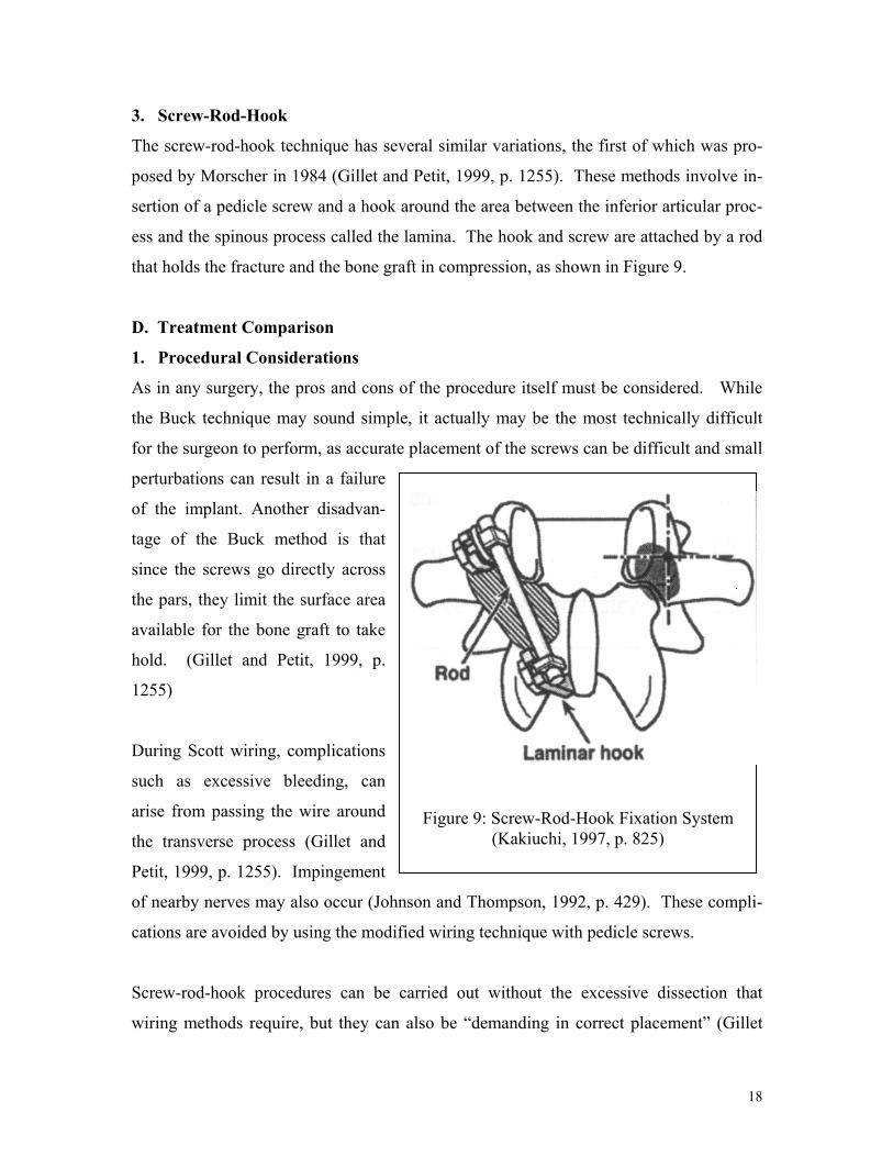
3. Screw-Rod-Hook
The screw-rod-hook technique has several similar variations, the first of which was pro-
posed by Morscher in 1984 (Gillet and Petit, 1999, p. 1255). These methods involve in-
sertion of a pedicle screw and a hook around the area between the inferior articular proc-
ess and the spinous process called the lamina. The hook and screw are attached by a rod
that holds the fracture and the bone graft in compression, as shown in Figure 9.
D. Treatment Comparison
1. Procedural Considerations
As in any surgery, the pros and cons of the procedure itself must be considered. While
the Buck technique may sound simple, it actually may be the most technically difficult
for the surgeon to perform, as accurate placement of the screws can be difficult and small
perturbations can result in a failure
of the implant. Another disadvan-
tage of the Buck method is that
since the screws go directly across
the pars, they limit the surface area
available for the bone graft to take
hold. (Gillet and Petit, 1999, p.
1255)
Figure 9: Screw-Rod-Hook Fixation System(Kakiuchi, 1997, p. 825)
During Scott wiring, complications
such as excessive bleeding, can
arise from passing the wire around
the transverse process (Gillet and
Petit, 1999, p. 1255). Impingement
of nearby nerves may also occur (Johnson and Thompson, 1992, p. 429). These compli-
cations are avoided by using the modified wiring technique with pedicle screws.
Screw-rod-hook procedures can be carried out without the excessive dissection that
wiring methods require, but they can also be “demanding in correct placement” (Gillet
18

and Petit, 1999, p. 1255), meaning that it can be hard for the surgeon to position the three
elements at the proper angle. The apparatus’s bulk can also irritate nearby soft tissue
(Kakiuchi, 1997, p. 820).
2. Biomechanical Testing
In the biomechanical testing of spondylolysis repair techniques, it is often a matter of
debate which parameters are most important to the success of the technique and should be
therefore be tested. Various factors have been tested and/or compared in in vitro studies.
Vathana and Prasartritha conducted a study on cadaveric human vertebrae in which they
measured anterior-posterior (front-back) translation of the two parts of the fractured ver-
tebra relative to each other under anterior-posterior load. They tested the three variations
of wiring technique -- Scott, “figure eight”, and pedicle screw -- and while they found no
significant differences in performance between the original Scott method and the figure
eight, the pedicle screw method yielded greater resistance to anterior-posterior move-
ment, thus reducing the most tensile stress across the fracture site. They also believed the
pedicle screw wiring to distribute a more uniform compression force over the bone graft
than the Scott or figure eight techniques. (Vathana and Prasartritha, 1998, pp. 824-828)
Kip, et al. tested a different factor using human vertebrae – stiffness across the pars dur-
ing a posteriorly directed force against the inferior articular facet. This force simulated
the shear force and moment at the pars experienced during lumbar hyperextension. They
tested spondylolytic vertebrae fixed with each of the three main techniques described
above in a testing apparatus similar to the one used by Cyron and Hutton in their experi-
ment. They were wary of the original Scott wiring technique, as they found it was unable
to resist even the slightest posteriorly directed force, so they used a wiring method similar
to the figure eight described above. They found that the Buck screws provided the stiff-
est repair, with mean stiffness of 64% of the stiffness of an intact (no pars fracture) verte-
brae, followed by the screw-rod-hook, which repaired the vertebra to 52% of its intact
stiffness. The wire repair was the least stiff, as it provided only 3.4% of intact stiffness.
They concluded that the Buck and screw-rod-hook methods might have a biomechanical
19

advantage over any wiring technique. Even though a wire repair holds a pars fracture to-
gether during flexion of the spine, it does not do so during extension; therefore “[i]ts use
to repair a defect whose probable cause is a repetitive hyperextension of the spine should
be questioned on biomechanical grounds.” (Kip, et al., 1994, pp. 2692-2696)
Deguchi, et al. conducted yet another study, this time using calf spines, which are ana-
tomically similar to human spines. They placed spinal segments with at least three verte-
brae still attached to each other into a testing apparatus. A spondylolytic vertebra in each
spinal segment was repaired by a wiring technique, Buck’s method, or a screw-rod-hook
method. The apparatus then loaded the segments in each of the following movements:
flexion, extension, and twisting. The rotation of intact and defective vertebrae with re-
spect to the vertebrae above and below them were measured, as were the motions across
the fractured pars. These measurements were compared to the rotations and motions of
the repaired vertebrae. It was found that intervertebral rotations were returned to near in-
tact levels in flexion and twisting for all the repair techniques, and in extension for all
techniques except wiring. Motion across the pars fracture was reduced to 78% of the un-
instrumented level by Buck’s technique, 66% by Scott’s wiring, and 83% by screw-rod-
hook fixation. These results agree with those of Kip, et al. in that they suggest that
Buck’s or screw-rod-hook technique should be used over wiring to repair spondylolysis.
(Deguchi, et al., 1999, p. 328-323)
3. Clinical Results
Clinical results have not shown any significant differences in the healing rates between
the different procedures. All three general techniques have yielded 70-90 percent success
rates for fusion of the pars fracture. (Kip, et al., 1994, p. 2692) These similar results, say
Kip, et al., suggest that many factors besides those measured in biomechanical studies go
into achieving a favorable clinical result (1994, p. 2696).
20

VI. CONCLUSION
The bulk of the research points to fatigue failure of the pars as the major cause of spondy-
lolysis. While some people may have a genetic predisposition for spondylolysis, under-
standing the mechanism of failure is essential if one is to avoid the lifestyles and activi-
ties that ultimately may cause the condition. Further research may be warranted on the
role of spinal ligaments in spondylolysis formation as well as on how other anatomical
factors, such as tight hamstrings, may contribute. Research in these areas may lead to an
increase in the effectiveness of conservative treatment techniques so that fewer surgeries
are necessary. But in the meantime, the current surgical methods seem to be effective in
healing the defect when non-invasive methods fail.
21

VII. WORKS CITED
Bartel, D.L. (2002) Professor, Sibley School of Mechanical Engineering, Cornell Uni-
versity. Comments on draft report. December, 2002. Cyron, B.M. and Hutton, W.C. (1978) The Fatigue Strength of the Lumbar Neural Arch
in Spondylolysis. The Journal of Bone and Joint Surgery. Vol. 60-B, Iss. 2: pp. 234-238.
Deguchi, M., Rapoff, A. and Zdeblick, T. (1999) Biomechanical Comparison of Spondy-
lolysis Fixation Techniques. Spine. Vol. 24, Iss. 4: pp. 328-333. Dreyzin, V. and Esses, S.I. (1994) A Comparative Analysis of Spondylolysis Repair.
Spine. Vol. 19, Iss. 17: pp. 1909-1915. Gatt, C.J., Hosea, T.M., Palumbo, R.C, and Zawadsky, J.P. (1997) Impact Loading of the
Lumbar Spine During Football Blocking. The American Journal of Sports Medi-cine. Vol. 25, Iss. 3: pp. 317-321.
Gillet, P. and Petit, M. (1999) Direct Repair of Spondylolysis Without Spondylolisthesis,
Using a Rod-Screw Construct and Bone Grafting of the Pars Defect. Spine. Vol. 24, Iss. 12: pp. 1252-1256.
Green, T.P., Allvey, J.C., and Adams, M.A. (1994) Bending of the Inferior Articular
Processes of Lumbar Vertebrae During Simulated Spinal Movements. Spine. Vol. 19, Iss. 23: pp. 2683-2691.
Inoue, H., Ohmori, K., Ishida, Y., Suzuki, K., Tanaka, E., and Murakami, S. (1998) Fi-
nite Element Analysis of the Lower Lumbar Neural Arch Under Facet Loading. Journal of Spinal Disorders. Vol. 11, Iss. 3: pp. 241-247.
Johnson, G.V. and Thompson, A.G. (1992) The Scott Wiring Technique for Direct Re-
pair of Lumbar Spondylolysis. Journal of Bone and Joint Surgery. Vol. 74-B, Iss. 3: pp. 426-430.
Kakiuchi, M. (1997) Repair of the Defect in Spondylolysis. Durable Fixation with
Pedicle Screws and Laminar Hooks. JBJA Journal of Bone and Joint Surgery. Vol. 79-A, Iss. 6: pp. 818-825.
Kip, P.C., Eses, S.I., Doherty, B.I., Alexander, J.W. and Crawford, M.J. (1994) Biome-
chanical Testing of Pars Defect Repairs. Spine. Vol. 19, Iss. 23: pp. 2692-2697.
22

Klemenesics, Z.L. and Kiss, R.M. (2000) The biomechanics of spondylolysis and spon-dylolysthesis. In: Proceedings of the 22nd Annual International Conference of the IEEE Engineering in Medicine and Biology Society, ed. Enderle. Piscataway, NJ: IEEE.
Martini, F.H., Timmons, M.J., and McKinley, M.P. (2000) Human Anatomy. Upper Sad-
dle River, NJ: Prentice-Hall. Motley, G., Nyland, J., Jacobs, J., and Caborn, D.N.M. (1998) The Pars Interarticularis
Stress Reaction, Spondylolysis, and Spondylolisthesis Progression. Journal of Athletic Training. Vol. 33, Iss. 4: pp. 351-358.
Nance, D and Hickey, M. (1999) Spondylolisthesis in Children and Adolescents. Or-
thopaedic Nursing. Vol. 18, Iss. 1: pp. 21-27. Pitzen, T., Geisler, F., Matthis, D., Muller-Storz, H., Barbier, D., Steudel, W., and
Feldges, A. (2002) A finite element model for predicting the biomechanical be-havior of the spine. Control Engineering Practice. Vol. 10: pp. 83-90.
Prasartritha, T. (2001) Surgical Repair of Pars Defects in Spondylolysis. Journal of the
Medical Association of Thailand. Vol. 84, Iss. 9: pp. 1235-1240. Salib, R.M. and Pettine, K.A. (1993) Modified Repair of a Defect in Spondylolysis or
Minimal Spondylolisthesis by Pedicle Screw, Segmental Wire Fixation, and Bone Grafting. Spine. Vol. 18, Iss. 4: pp. 440-443.
Theiss, S.M. (2001) Isthmic Spondylolisthesis and Spondylolysis. Journal of the South-
ern Orthopaedic Association. Vol. 10, Iss. 3: pp. 164-172. Vathana, P. and Prasartritha, T. (1998) A Biomechanic Study of the Surgical Repair
Technique of Pars Defect in Spondylolysis. Journal of the Medical Association of Thailand. Vol. 81, Iss. 11: pp. 824-828.
Yamamoto, S., Tanaka, E., Mihara, K., Inoue, H., and Ohmori, K. (1999) Finite Ele-
ment Analysis of Spondylolysis Taking Account of Nonlinear Mechanical Proper-ties of Ligaments and Annulus Fibers. JSME International Journal. Series C, Vol. 42, Iss. 3: pp. 521-531.
23

VIII. APPENDICES
Appendix A: Anatomical Diagrams
(Adapted from Martini, et al., 2000, pp. 161 & 163)
Left: Vertebral Levels
Below: Vertebrae
-Left: Lateral and inferior view
-Right: Posterior view
24
Pars

Appendix B: Principal Stress Formula
The principal stresses on an element (σI, σII, σIII in 3-D) are the stresses in the direction
where shear stress equals zero and are the maximum normal stresses in a structure. Prin-
cipal stresses are given (in 2-D) by the following formula:
22
, 4)(
2τ
σσσσσ +
−±
+= yxyx
III
Where x and y denote the stresses in each of the two dimensions.
25