![Currents on Generalized Yagi StructuresAs recounted by Professor Uda 11,2], the Yagi-Uda antenna was invented in 1926. Further practical and theoretical studies were undertaken, but,](https://static.fdocuments.in/doc/165x107/5e94290536a67159ca4acd82/currents-on-generalized-yagi-structures-as-recounted-by-professor-uda-112-the.jpg)
A Study of Stacked Arrays of Yagi-Uda Antennas Jay Terleski, WX0B 1.
91
A Study of Stacked Arrays of Yagi-Uda Antennas Jay Terleski, WX0B 1
-
Upload
miya-cranson -
Category
Documents
-
view
238 -
download
3
Transcript of A Study of Stacked Arrays of Yagi-Uda Antennas Jay Terleski, WX0B 1.
A Study of Stacked Arraysof
Yagi-Uda Antennas
Jay Terleski, WX0B
1
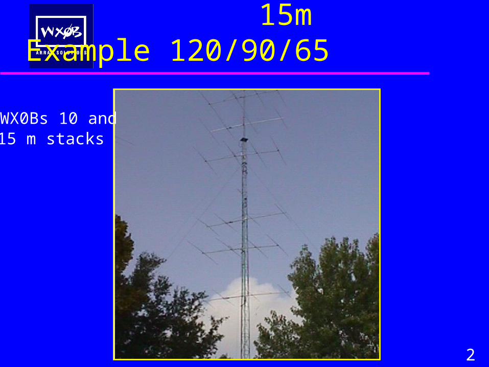
15m Example 120/90/65
2
WX0Bs 10 and15 m stacks
15m Example
3
• A good model which applies to 20 and 10 meters will be a 4 element 23 foot design. Most antenna manufactures offer a similar antenna to this design.
• 40 meters we will will use 2 and 3 element beams common to Hams.
Why do we stack yagis
• Gain • Clean up pattern • Control of Take-off angle • Beam in multiple directions• Suppress rain, snow, wind static
4
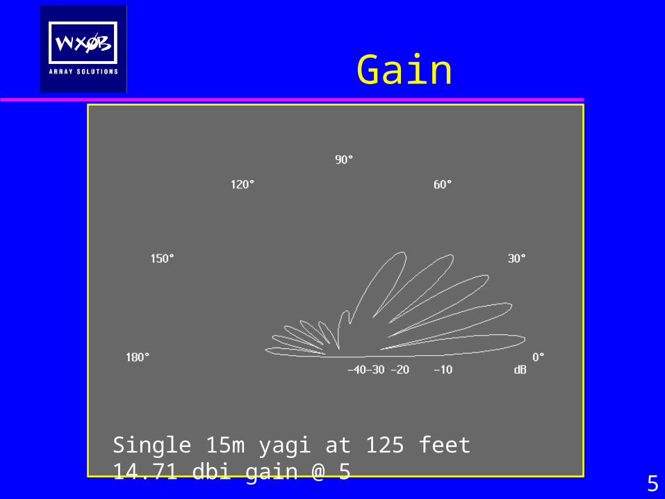
Gain
5
Single 15m yagi at 125 feet 14.71 dbi gain @ 5

Gain
6
125/95 stack with 17.01 dbi gain @ 6 degrees

Gain
7
120/90 stack with 17.01 dbi gain @ 6 degrees125/95/65 stack 18.34 dbi gain @ 6 degrees
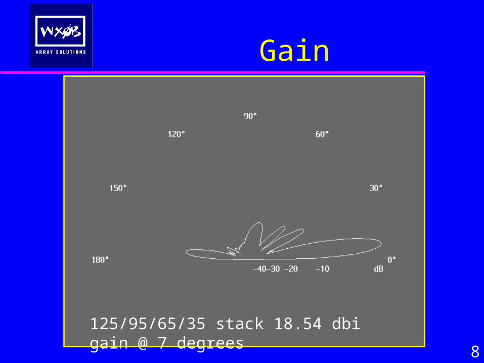
Gain
8
125/95/65/35 stack 18.54 dbi gain @ 7 degrees
Why do we stack yagis
• Gain • Control of Take-off angle
9
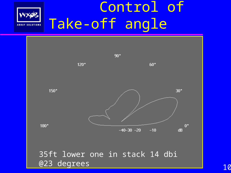
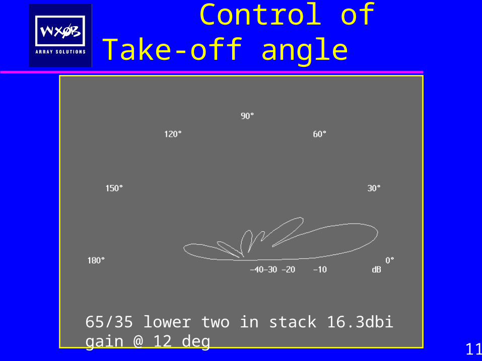
Control of Take-off angle
10
35ft lower one in stack 14 dbi @23 degrees
Control of Take-off angle
11
65/35 lower two in stack 16.3dbi gain @ 12 deg
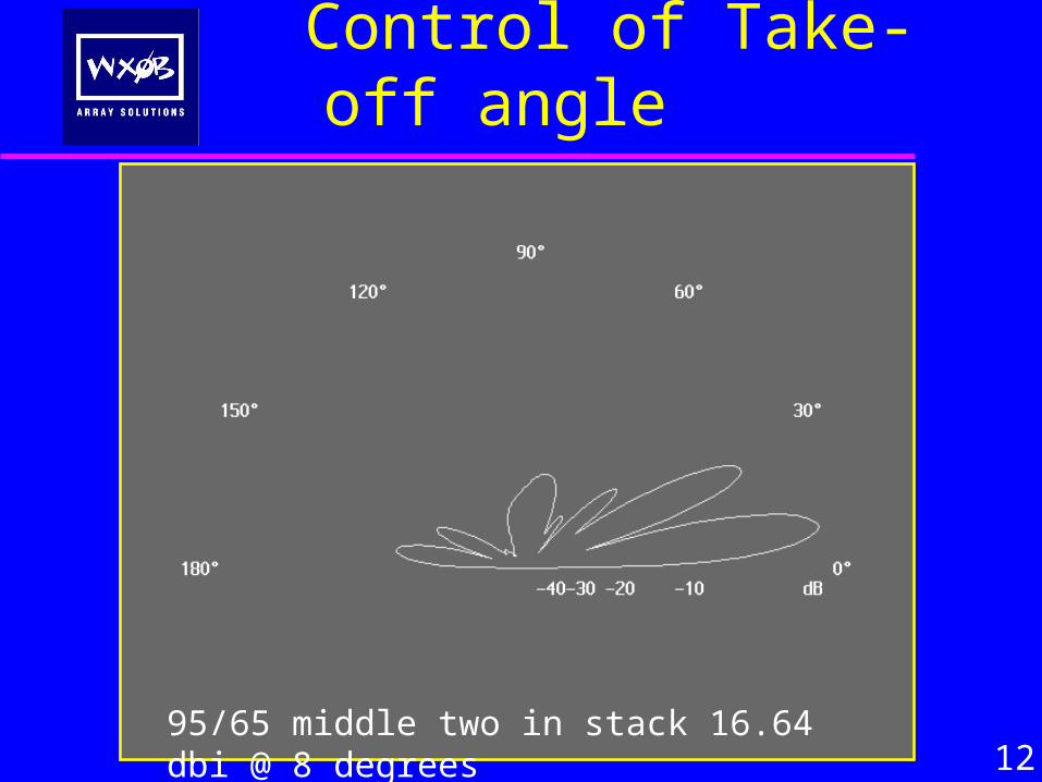
1295/65 middle two in stack 16.64 dbi @ 8 degrees
Control of Take-off angle
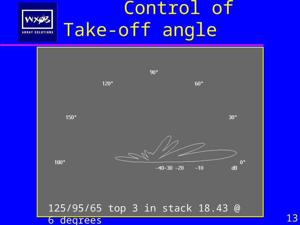
13125/95/65 top 3 in stack 18.43 @ 6 degrees
Control of Take-off angle
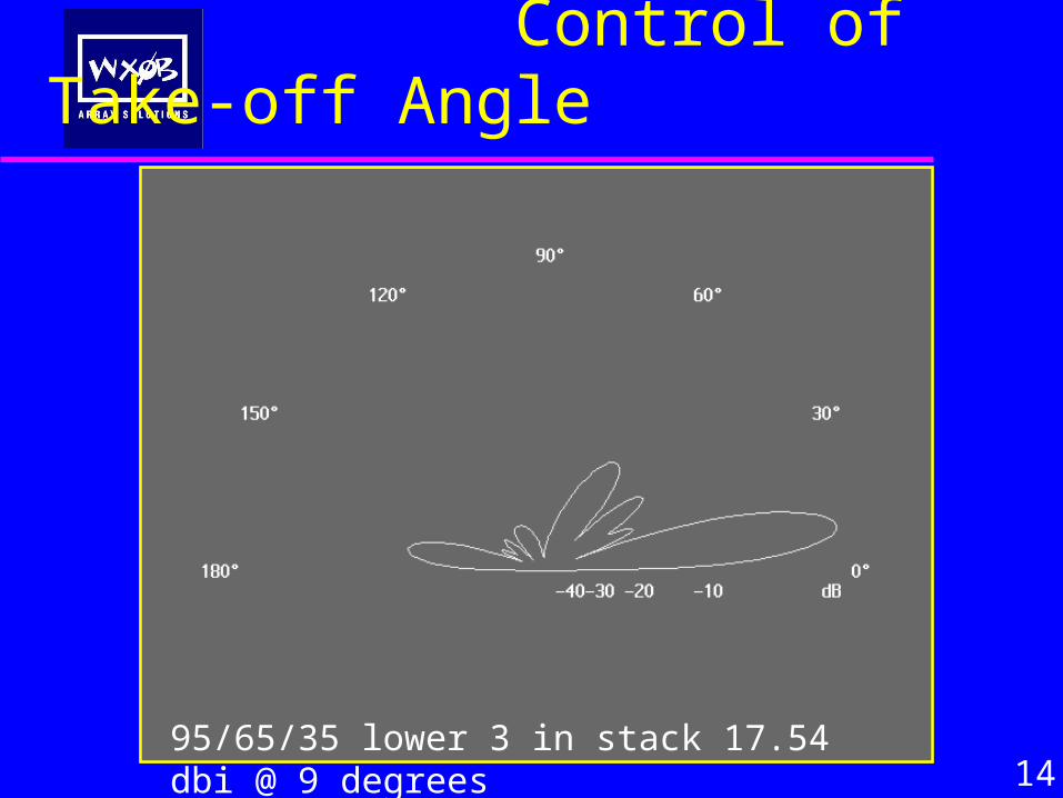
Control of Take-off Angle
1495/65/35 lower 3 in stack 17.54 dbi @ 9 degrees
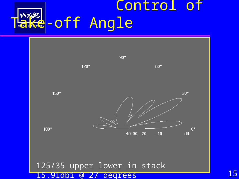
Control of Take-off Angle
15125/35 upper lower in stack 15.91dbi @ 27 degrees
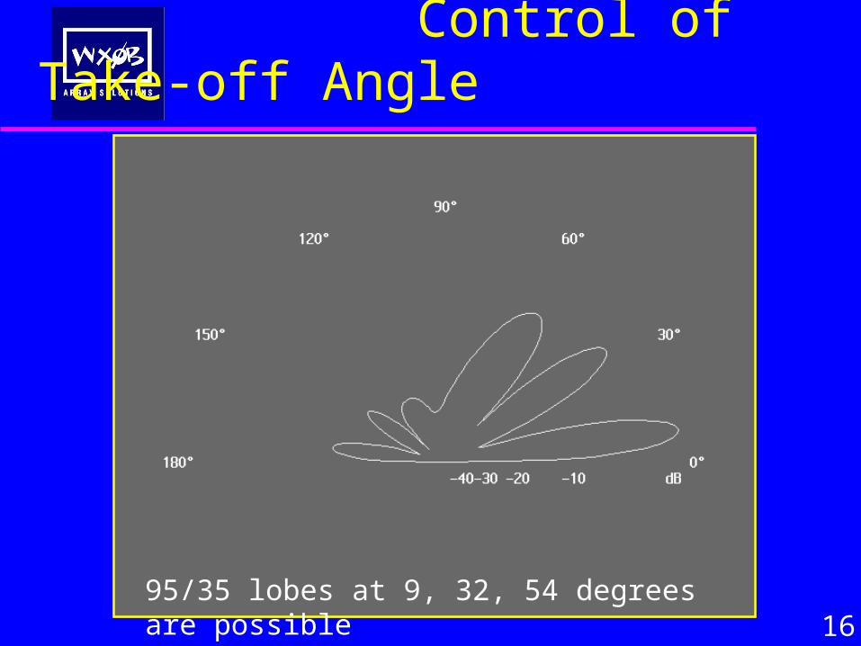
Control of Take-off Angle
1695/35 lobes at 9, 32, 54 degrees are possible
Why do we stack yagis
• Gain • Clean up pattern • Control of Take-off angle
•
17
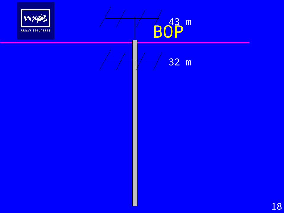
BOP
18
43 m
32 m
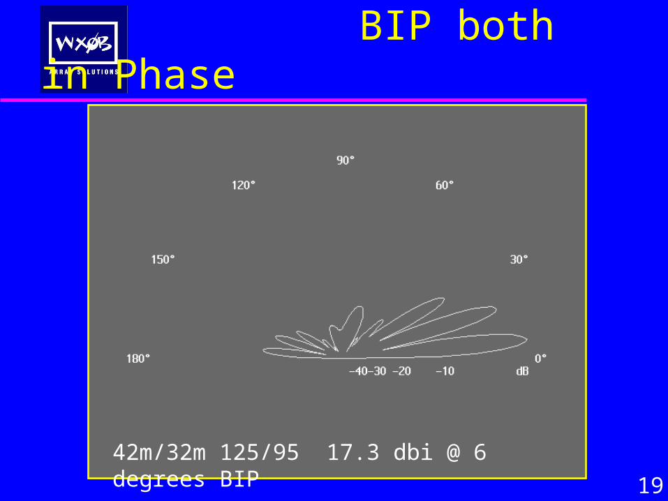
BIP both in Phase
19
42m/32m 125/95 17.3 dbi @ 6 degrees BIP
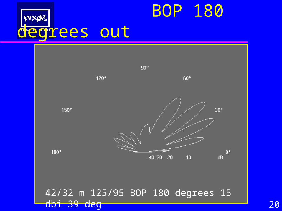
BOP 180 degrees out
2042/32 m 125/95 BOP 180 degrees 15 dbi 39 deg
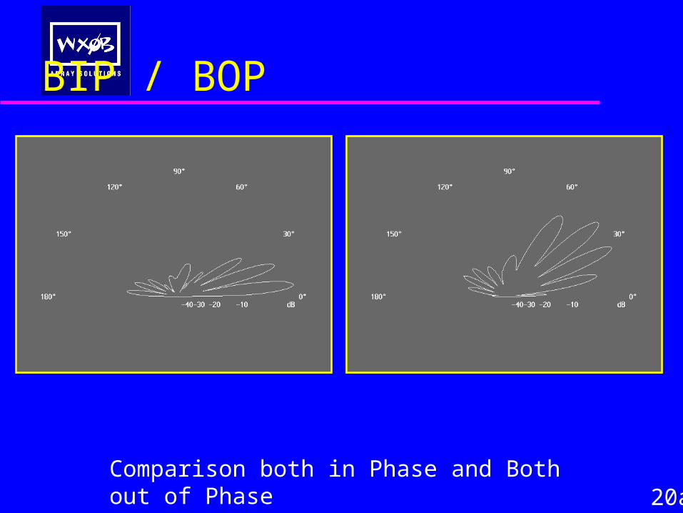
BIP / BOP
20aComparison both in Phase and Both out of Phase
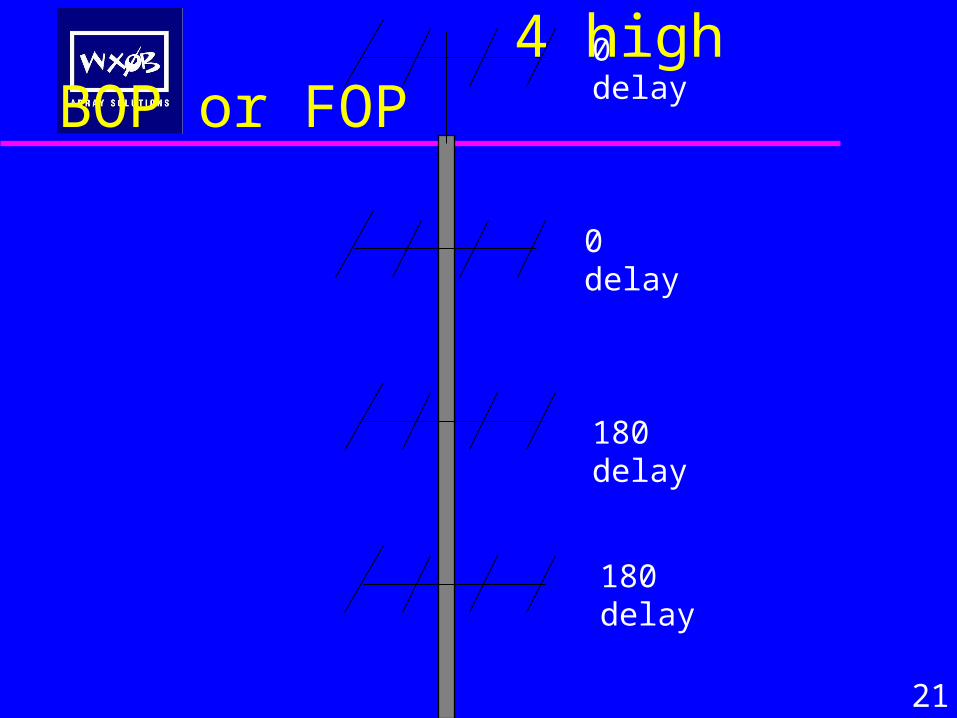
4 high BOP or FOP
21
0 delay
0 delay
180 delay
180 delay
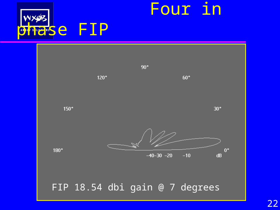
Four in phase FIP
22
FIP 18.54 dbi gain @ 7 degrees

FOP
23
FOP 17.67 dBi @ 17 degrees, bottom 2 BOP
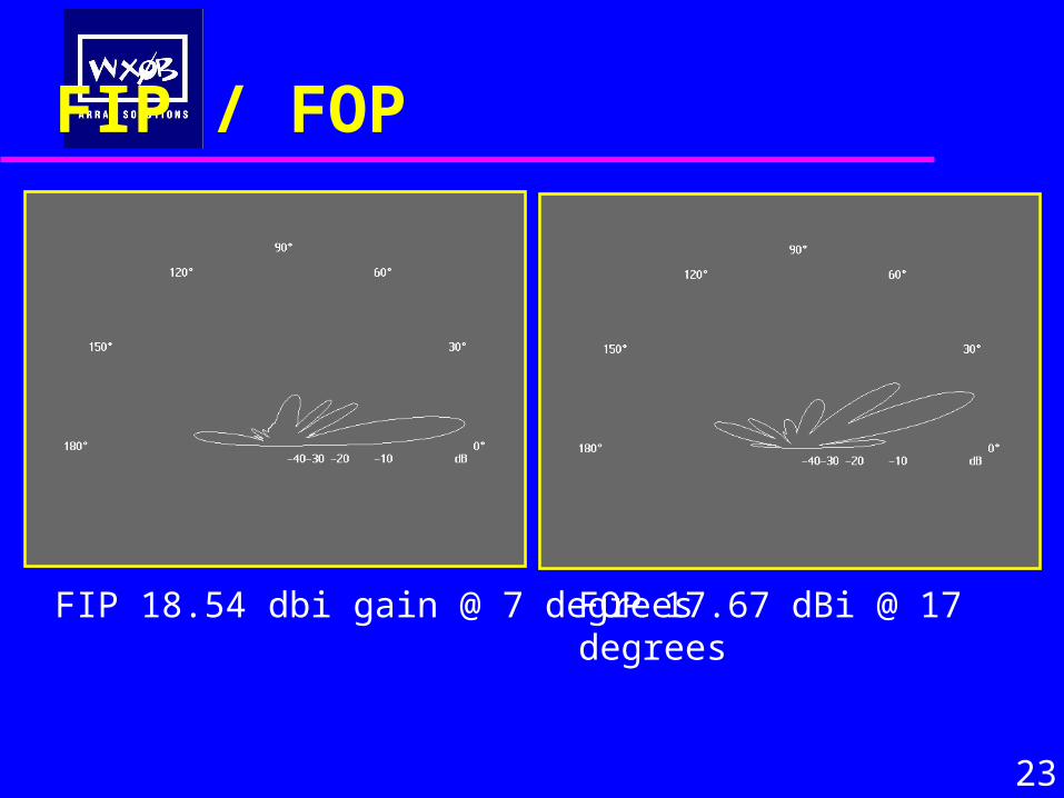
FIP / FOP
23
FOP 17.67 dBi @ 17 degrees
FIP 18.54 dbi gain @ 7 degrees
Some BOP rules
Gain is always less at main lobe
Phase delays that are not 180 do
not work !
OR DO THEY???OR DO THEY???
25
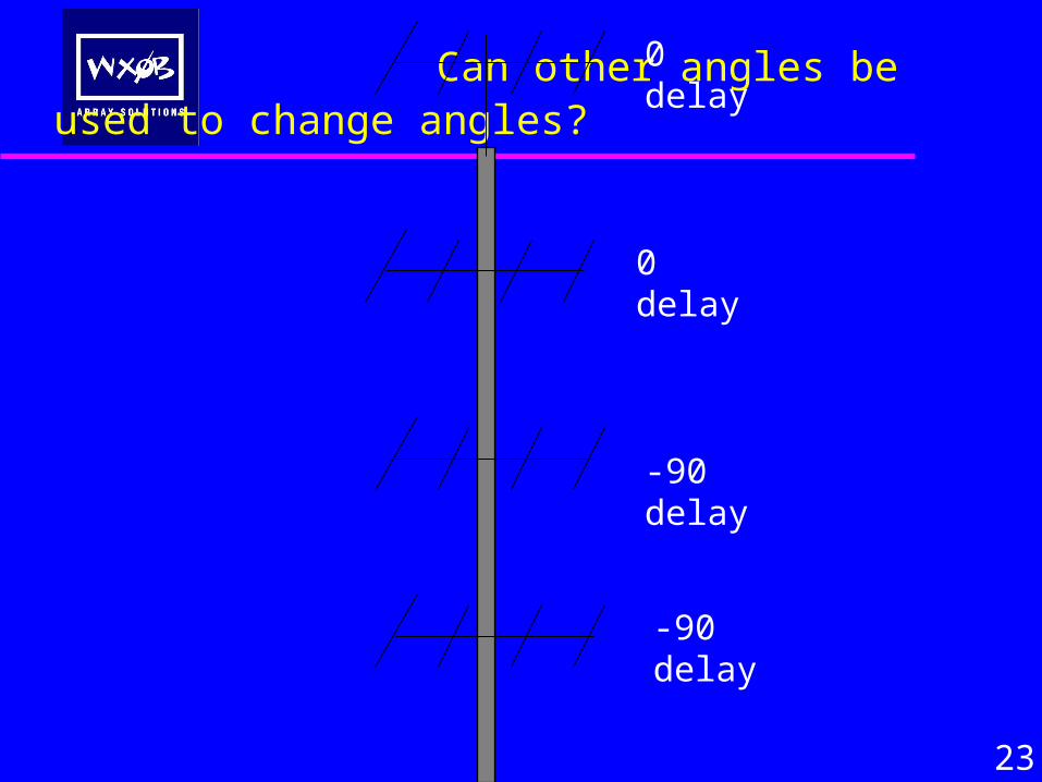
Can other angles be used to change angles?
23
0 delay
0 delay
-90 delay
-90 delay
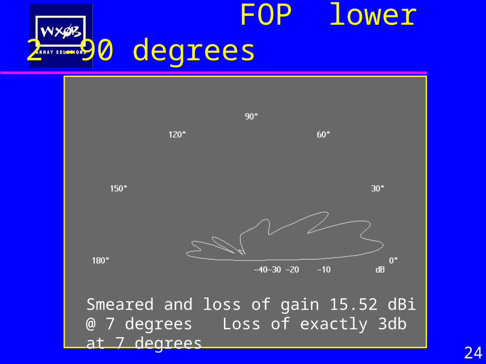
FOP lower 2 -90 degrees
24
Smeared and loss of gain 15.52 dBi @ 7 degrees Loss of exactly 3db at 7 degrees
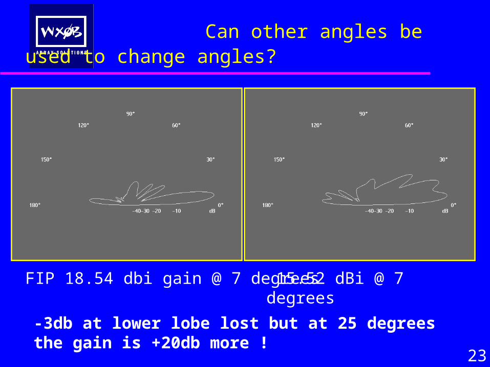
Can other angles be used to change angles?
23
FIP 18.54 dbi gain @ 7 degrees 15.52 dBi @ 7 degrees
-3db at lower lobe lost but at 25 degrees the gain is +20db more !
Some BOP rules
Gain is always less at main lobe
But the gain may be better at all the
nulls.
Lets test this on two beams
25
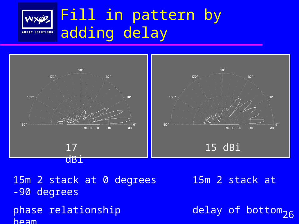
Fill in pattern by adding delay
15m 2 stack at 0 degrees 15m 2 stack at -90 degrees
phase relationship delay of bottom beam
17 dBi
26
15 dBi
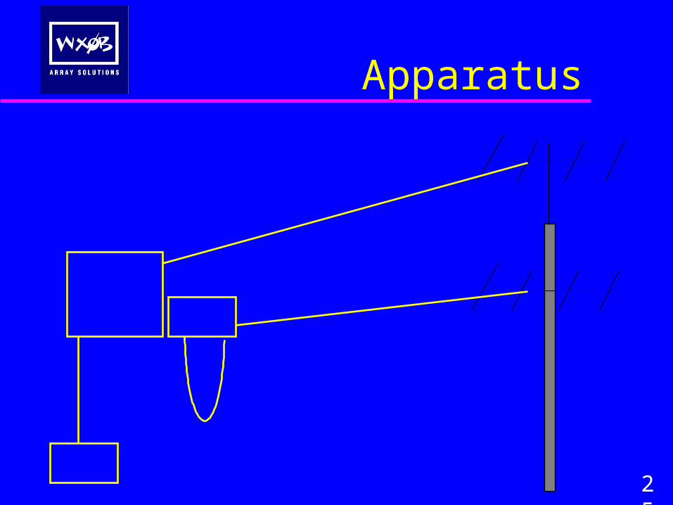
Apparatus
25
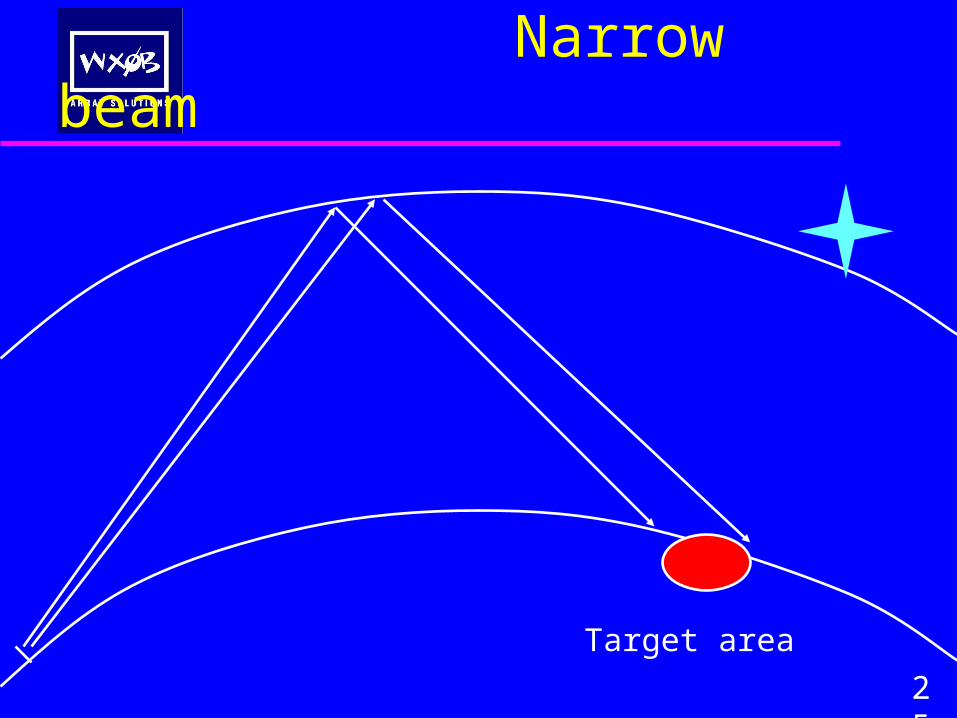
Narrow beam
25
Target area
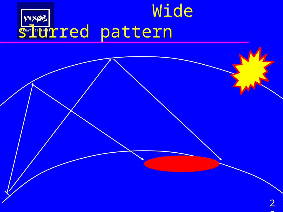
Wide slurred pattern
25
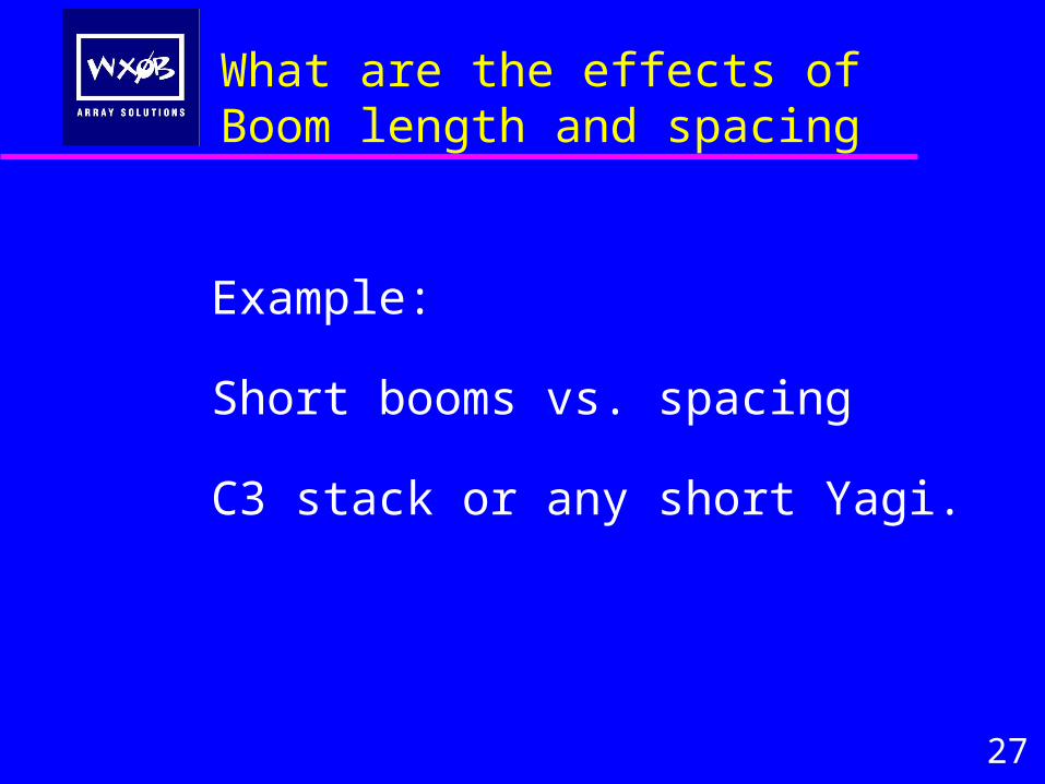
What are the effects of Boom length and spacing
Example:
Short booms vs. spacing
C3 stack or any short Yagi.
27
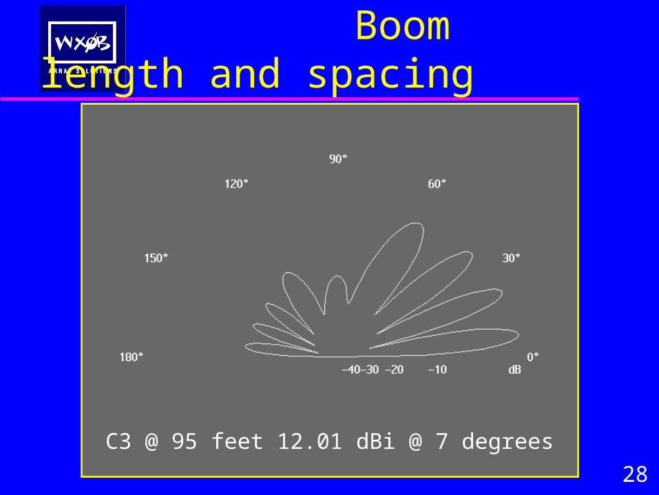
Boom length and spacing
28
C3 @ 95 feet 12.01 dBi @ 7 degrees
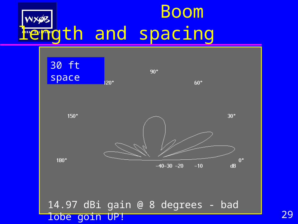
Boom length and spacing
2914.97 dBi gain @ 8 degrees - bad lobe goin UP!
30 ft space
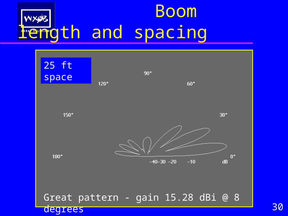
Boom length and spacing
30Great pattern - gain 15.28 dBi @ 8 degrees
25 ft space
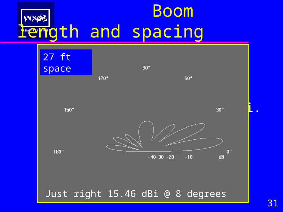
Boom length and spacing
Short booms vs. spacing
C3 stack or any short Yagi.
31Just right 15.46 dBi @ 8 degrees
27 ft space
Boom length and spacing
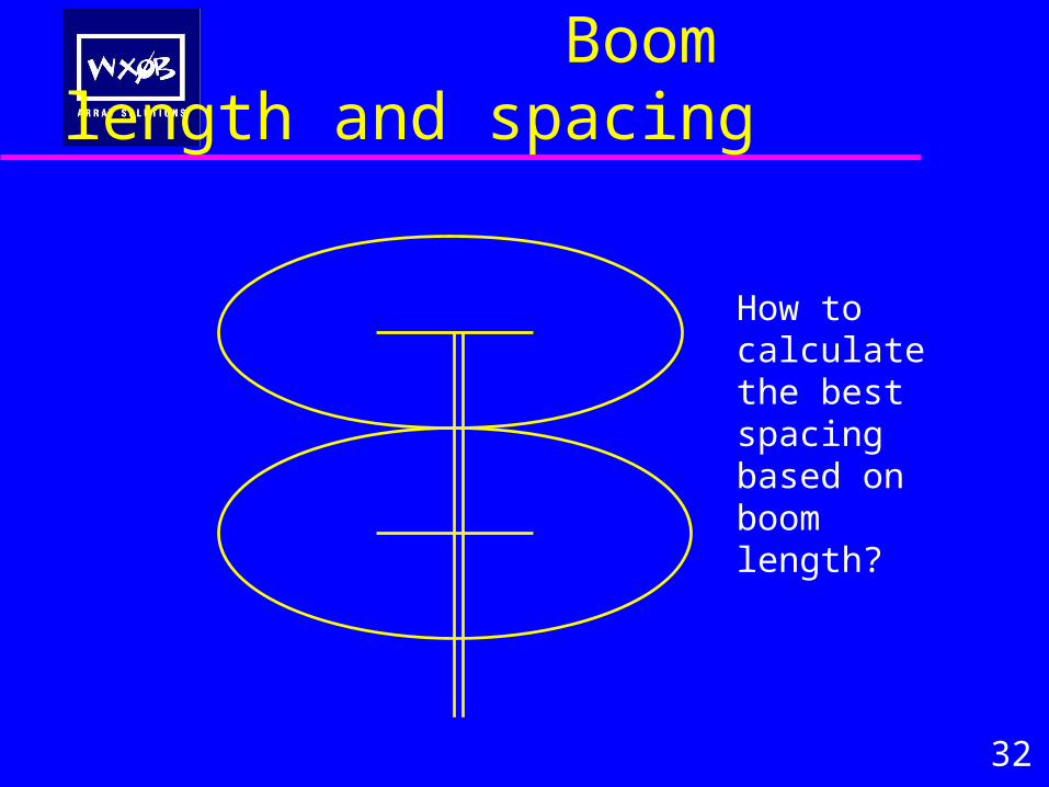
32
How to calculate the best spacing based on boom length?
Boom length and spacing
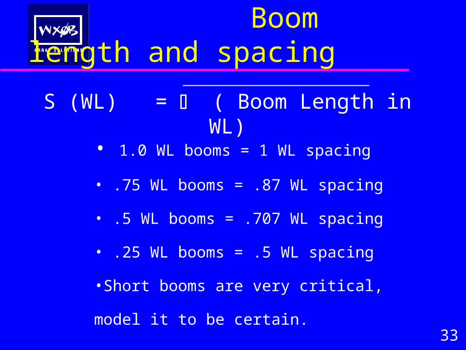
• 1.0 WL booms = 1 WL spacing
• .75 WL booms = .87 WL spacing
• .5 WL booms = .707 WL spacing
• .25 WL booms = .5 WL spacing
•Short booms are very critical, model it to be certain.
33
S (WL) = ( Boom Length in WL)
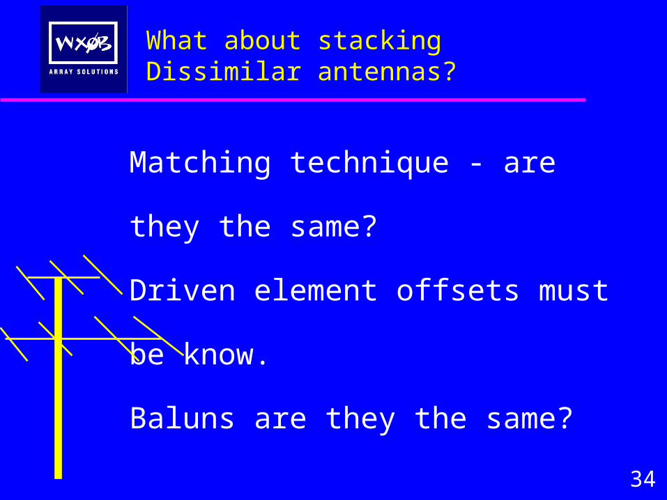
What about stacking Dissimilar antennas?
Matching technique - are they the
same?
Driven element offsets must be know.
Baluns are they the same?
34
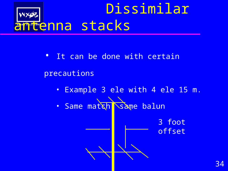
Dissimilar antenna stacks
• It can be done with certain precautions
• Example 3 ele with 4 ele 15 m.
• Same match, same balun
34
3 foot offset
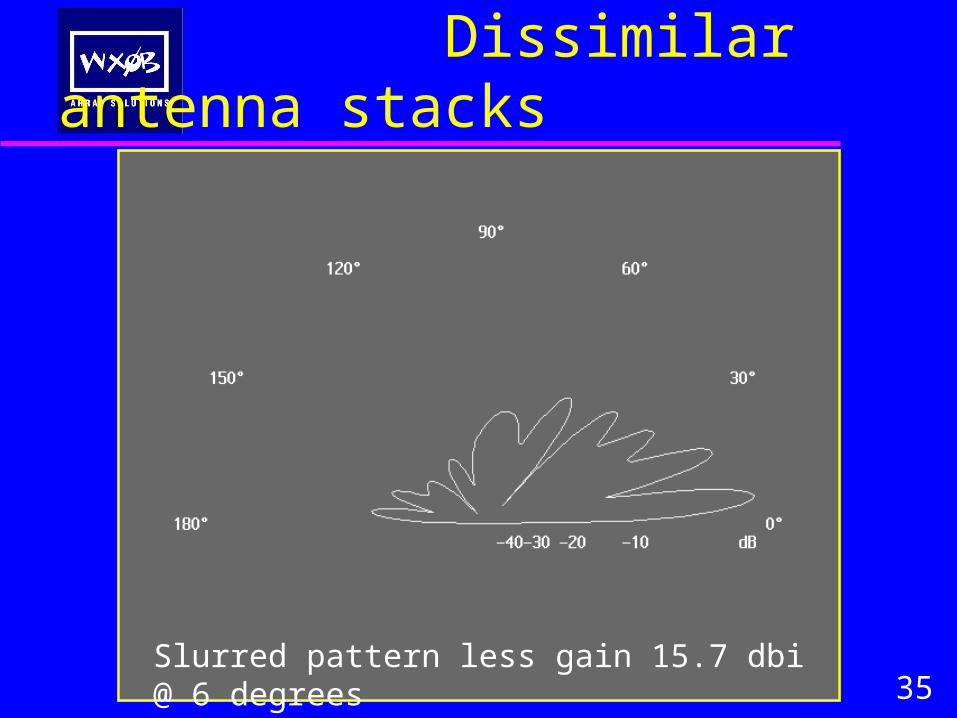
Dissimilar antenna stacks
35Slurred pattern less gain 15.7 dbi @ 6 degrees
Dissimilar antenna stacks
36
3 feet / 44.4 ft (WL) X 360 degrees = 24.3 degrees of delay is required to put these antennas in phase.
3 feet X .66 (VF of RG213) = 1.98 feet of coax would need to be added to the leading driven element.
Lets correct the model by adding in the delay line and see the resulting pattern
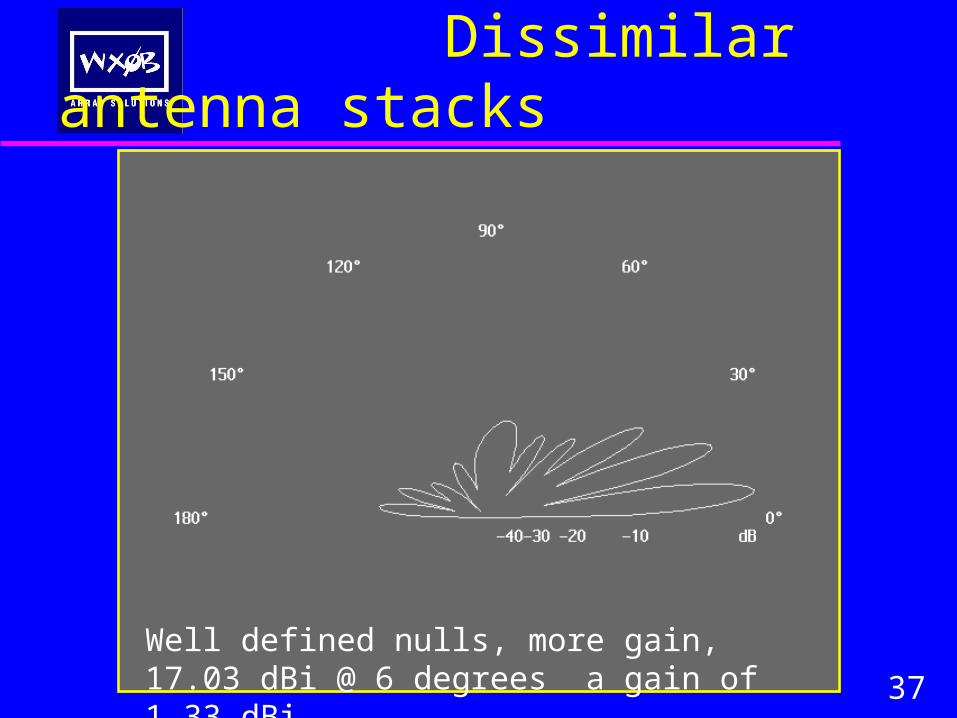
Dissimilar antenna stacks
37
Well defined nulls, more gain, 17.03 dBi @ 6 degrees a gain of 1.33 dBi
Dissimilar antenna stacks
37
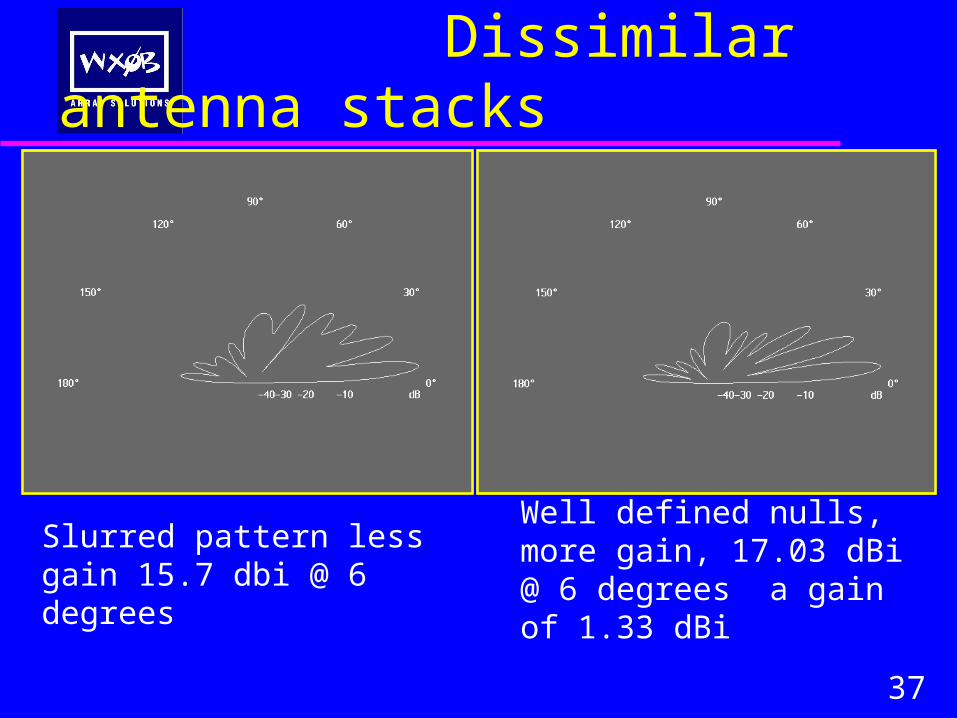
Well defined nulls, more gain, 17.03 dBi @ 6 degrees a gain of 1.33 dBi
Slurred pattern less gain 15.7 dbi @ 6 degrees
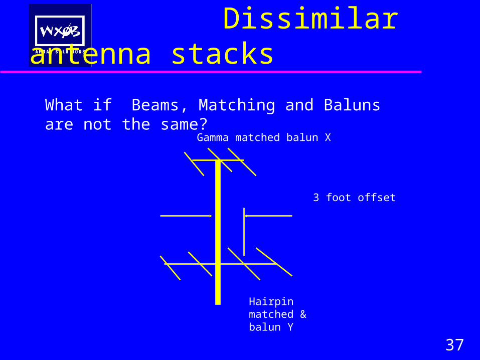
Dissimilar antenna stacks
37
What if Beams, Matching and Baluns are not the same?
3 foot offset
Gamma matched balun X
Hairpin matched & balun Y
Dissimilar antenna stacks
37
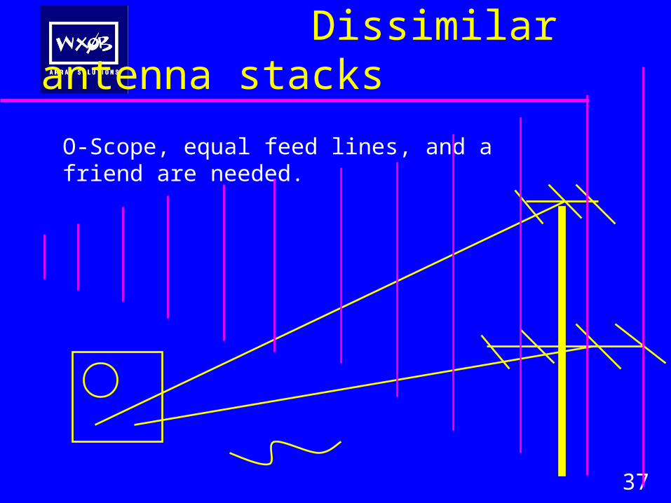
O-Scope, equal feed lines, and a friend are needed.
Dissimilar antenna stacks
37
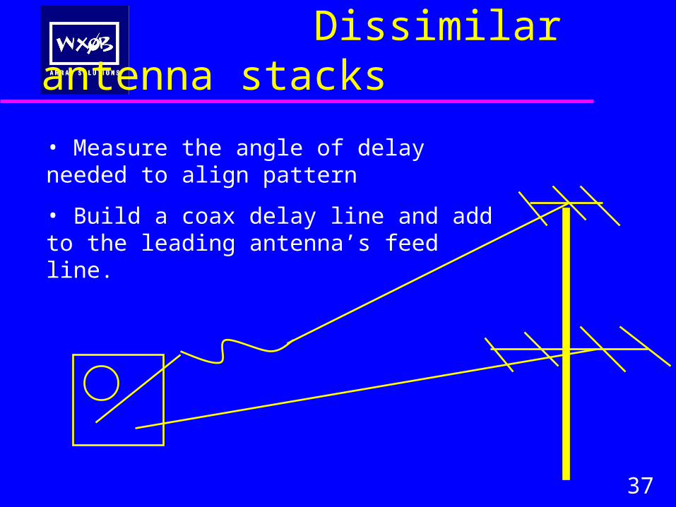
• Measure the angle of delay needed to align pattern
• Build a coax delay line and add to the leading antenna’s feed line.
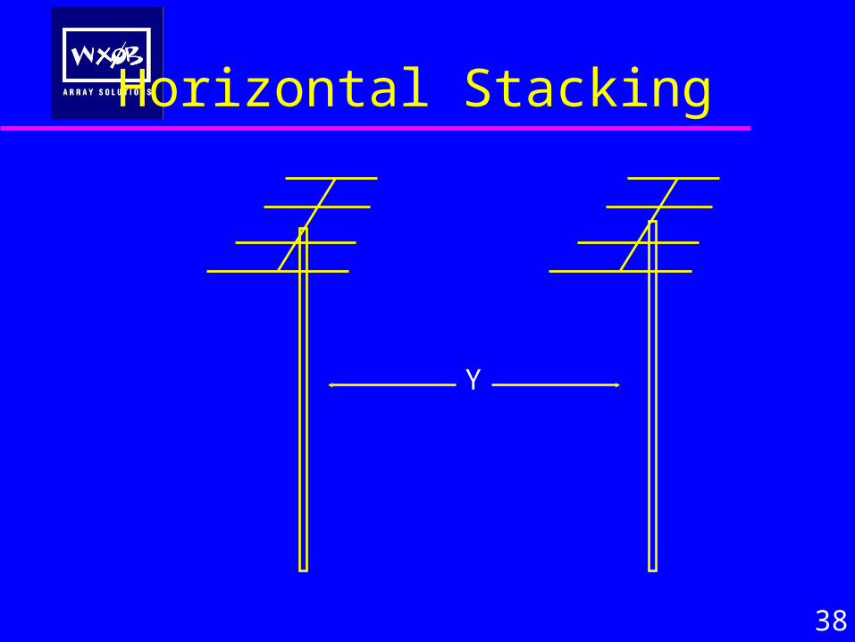
Horizontal Stacking
38
Y
Horizontal Stacking
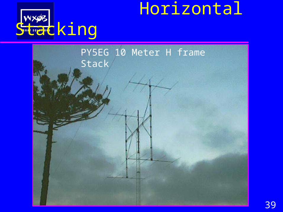
39
PY5EG 10 Meter H frame Stack
Horizontal Stacking
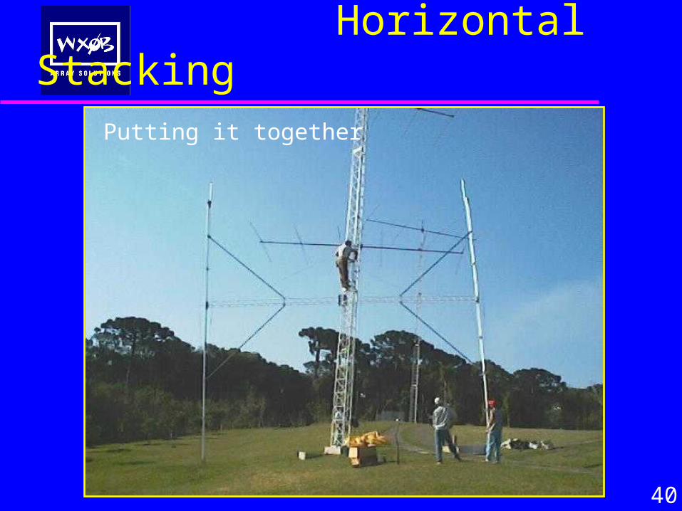
40
PY5EG 10 Meter H frame StackPutting it together
Horizontal Stacking
41
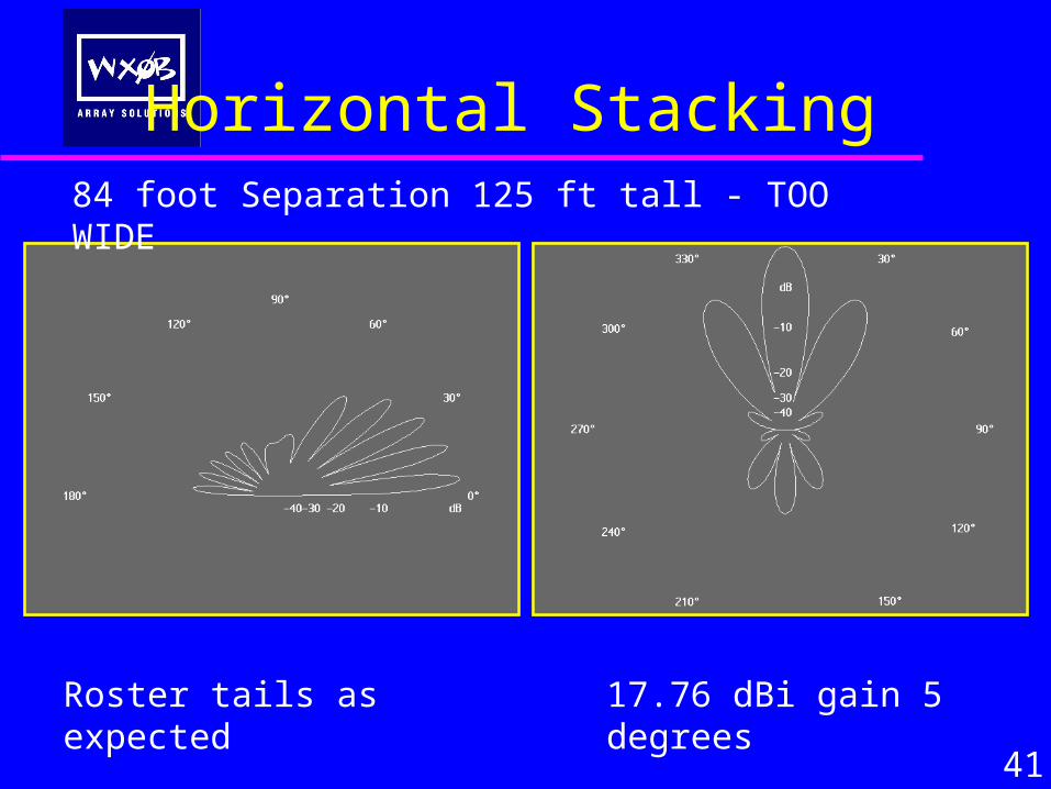
17.76 dBi gain 5 degreesRoster tails as expected
84 foot Separation 125 ft tall - TOO WIDE
Horizontal Stacking
42
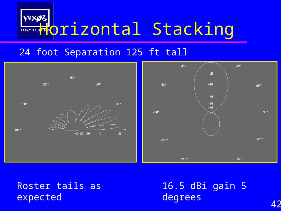
16.5 dBi gain 5 degreesRoster tails as expected
24 foot Separation 125 ft tall
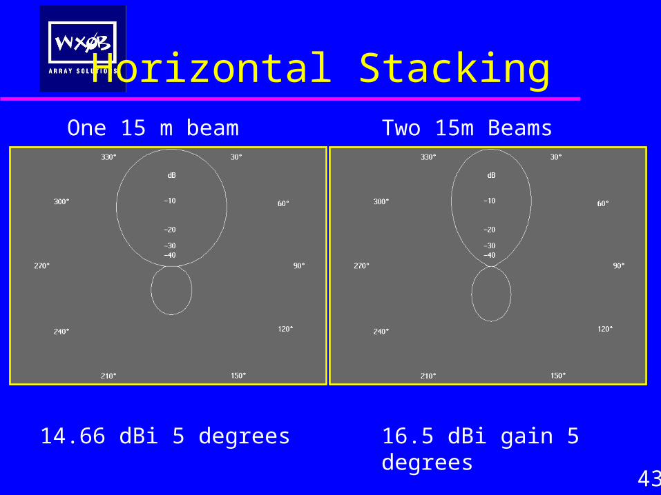
Horizontal Stacking
43
16.5 dBi gain 5 degrees14.66 dBi 5 degrees
One 15 m beam Two 15m Beams
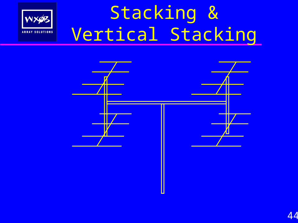
Horizontal Stacking & Vertical Stacking
44
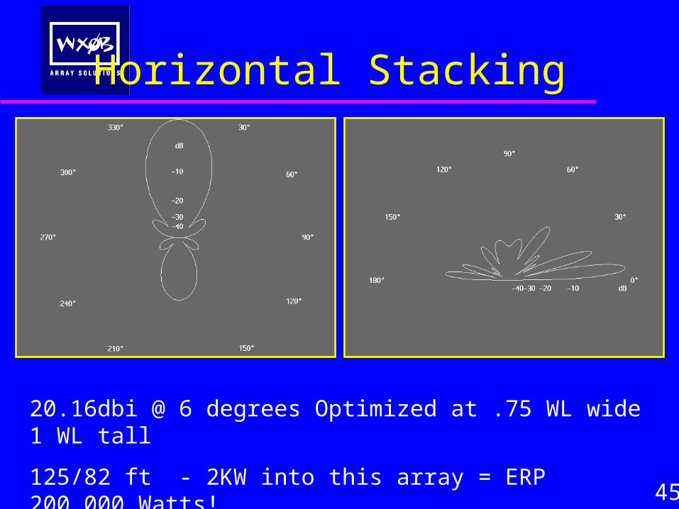
Horizontal Stacking
45
20.16dbi @ 6 degrees Optimized at .75 WL wide 1 WL tall
125/82 ft - 2KW into this array = ERP 200,000 Watts!
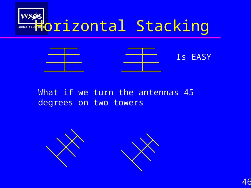
Horizontal Stacking
46
Is EASY
What if we turn the antennas 45 degrees on two towers
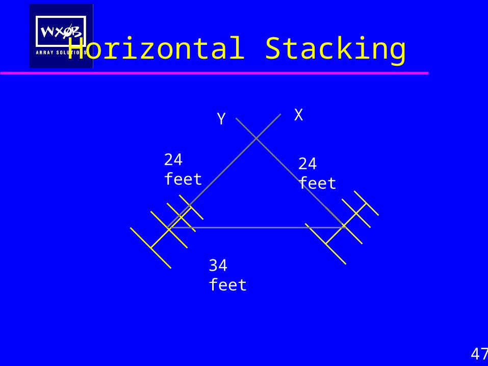
47
XY
34 feet
24 feet24 feet
Horizontal Stacking
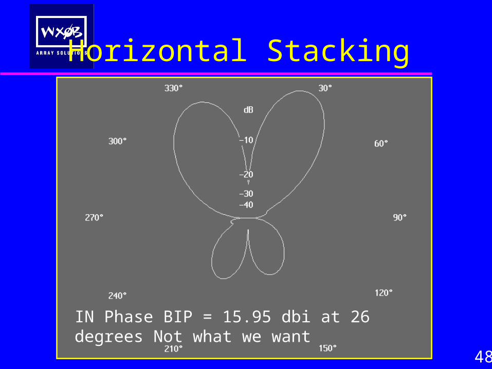
Horizontal Stacking
48
IN Phase BIP = 15.95 dbi at 26 degrees Not what we want
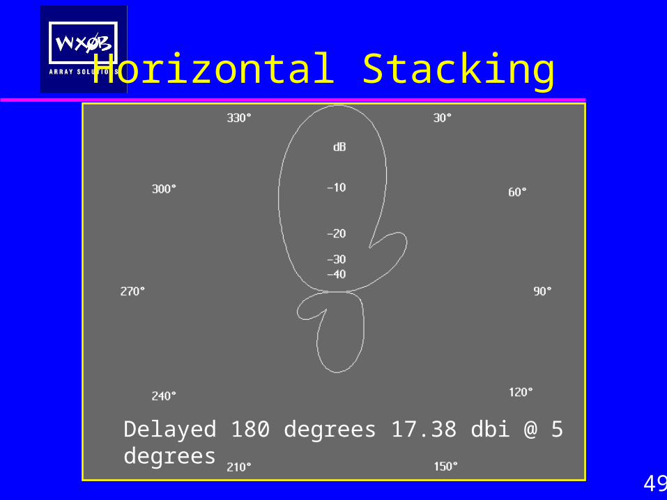
Horizontal Stacking
49
Delayed 180 degrees 17.38 dbi @ 5 degrees
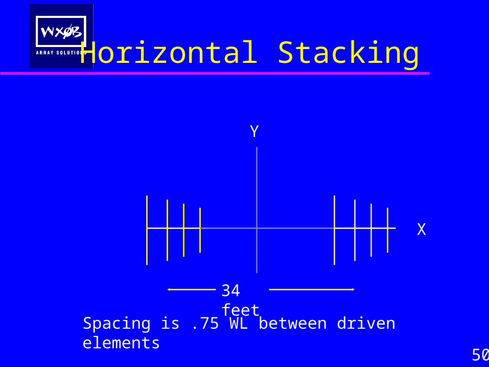
50
X
Y
34 feet
Spacing is .75 WL between driven elements
Horizontal Stacking
Horizontal Stacking
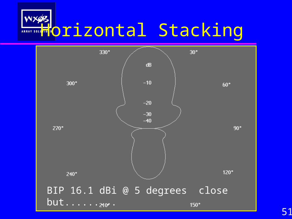
51
BIP 16.1 dBi @ 5 degrees close but.........
Horizontal Stacking
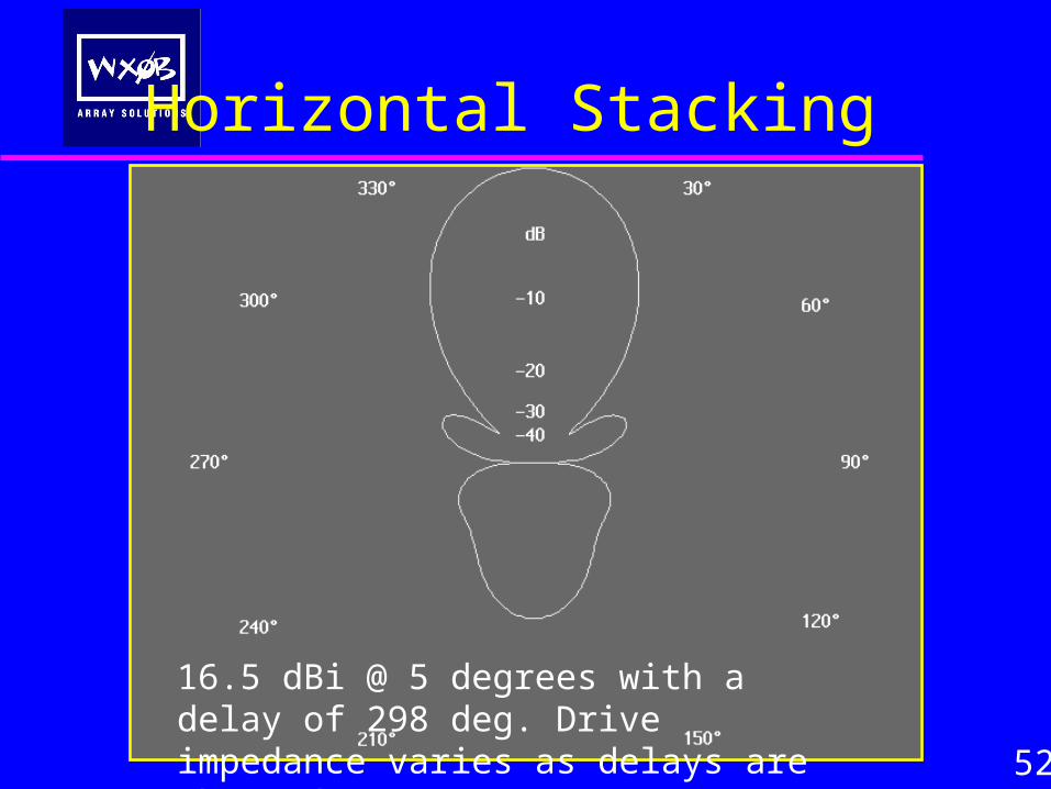
52
16.5 dBi @ 5 degrees with a delay of 298 deg. Drive impedance varies as delays are changed
Issues With Stagger Types That Turn
53
• Close coupling is a problem
• Drive impedance vary widely as the array turns
• Matching will be a problem - very difficult to adjust
• This type of array is probably not suitable unless everything remains fixed as in an H-Frame or parallel tower single direction arrays
• More work needs to be done on LAPA type arrays for amateur work
What Happens When I Beam in Multiple Directions?
54
• Will rotating a Yagi 180 degrees in a stack cancel the forward pattern intended? Or will it allow the forward pattern to survive?
• Will rotating a Yagi in a stack achieve the intended pattern? That is, to beam in two directions at once? Or will it mess up the pattern?
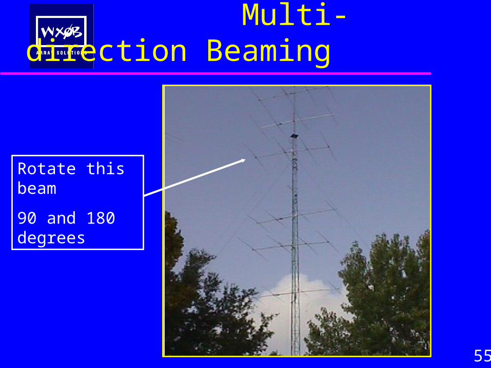
Multi-direction Beaming
55
Rotate this beam
90 and 180 degrees
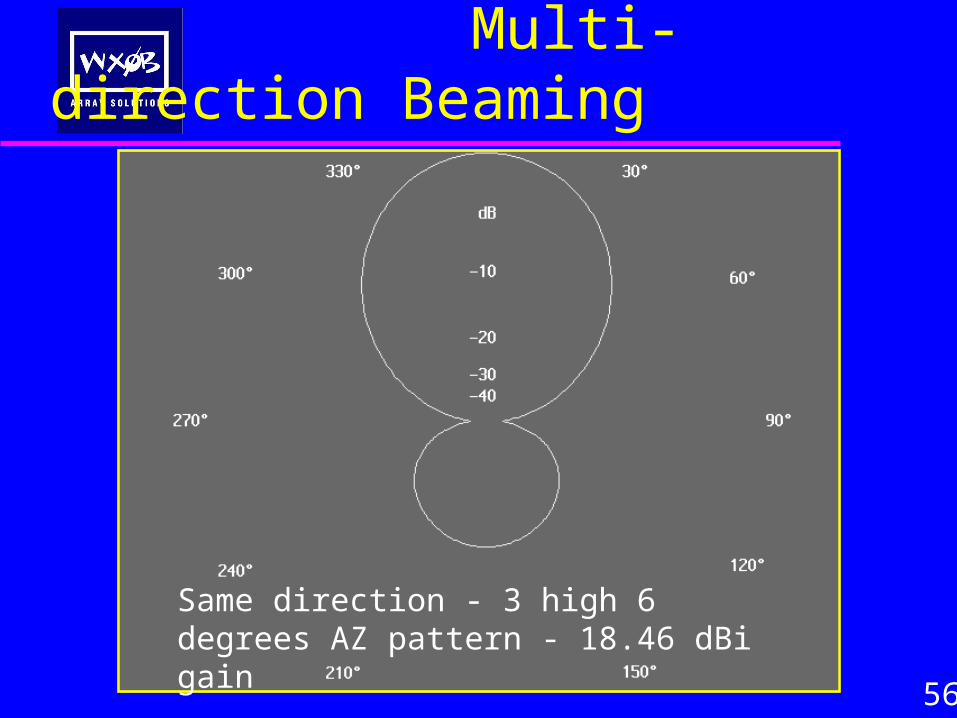
Multi-direction Beaming
56
Same direction - 3 high 6 degrees AZ pattern - 18.46 dBi gain
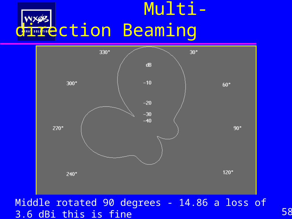
Multi-direction Beaming
58Middle rotated 90 degrees - 14.86 a loss of 3.6 dBi this is fine
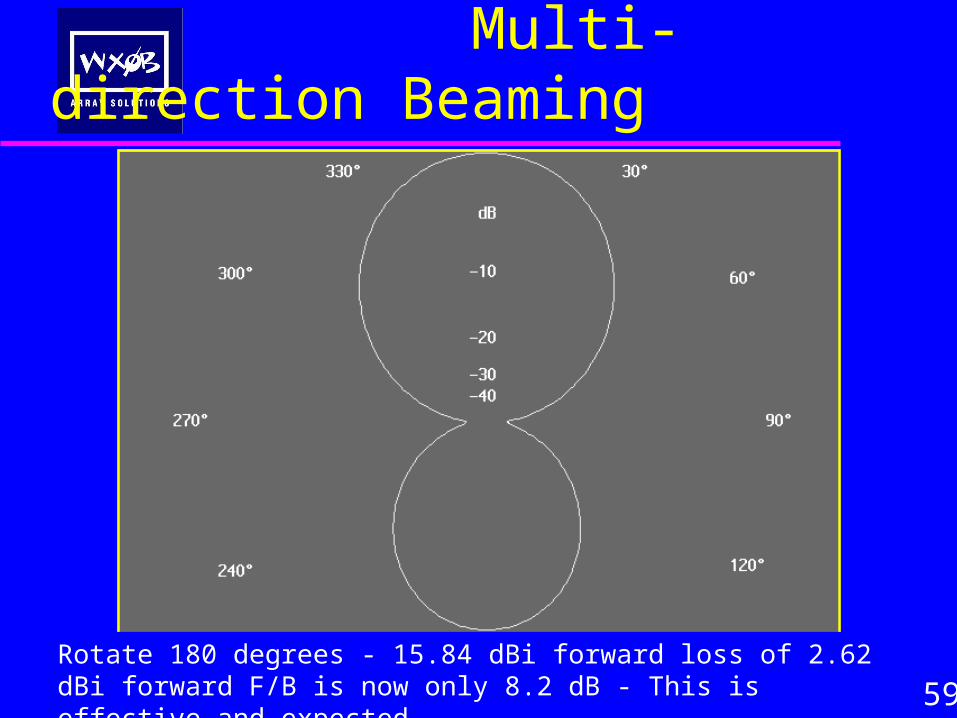
Multi-direction Beaming
59Rotate 180 degrees - 15.84 dBi forward loss of 2.62 dBi forward F/B is now only 8.2 dB - This is effective and expected
Multi-direction Beaming
60
• Will rotating a Yagi in a stack achieve the intended pattern? That is, to beam in two directions at once?
• Yes, all beams in a properly spaced stack may be rotated individually without regard to cancellation.
• Will rotating a Yagi 180 degrees achieve the intended pattern?
•Yes, all three are fine to rotate.
Summary - GAIN
VERTICAL STACKS must be properly spaced
• Gain of 2.2-3 dB from adding second antenna
• Gain of 1.5-2 dB by adding a third antenna
• Gain of .5 - 1 dB by adding a fourth antenna
61
Summary -Take off Angle
• Switching allows control of take off angle including BOP
• Angle of lobes can be bad due to poor spacing of yagis
• Stack lobe will always slightly higher than top yagi alone
• 18-20+ dB of difference can be seen from peak to null -
This is more important than the raw gain of the array!
Intentionally adding phase delay to one antenna can widen
the main lobes to create a larger target and minimize nulls
62
Summary BIP/BOP
• BOP useful for gaining high angle lobe from a 2 high stack at
the sacrifice of only 3db of max stack gain
• This could be a secret weapon in SS and NAQP contests
• A high stack can be made to act like its close to the ground
63
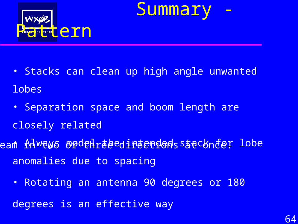
Summary - Pattern
• Stacks can clean up high angle unwanted lobes
• Separation space and boom length are closely related
• Always model the intended stack for lobe anomalies due to
spacing
• Rotating an antenna 90 degrees or 180 degrees is an effective way
• Intentionally slurring a pattern can increase the target area
64
to beam in two or three directions at once.
Example - 40 meter stack
65
• How does a 3 ele full size 40 meter beam compare to a stack of shorty 40 meter beams like the CC 420?
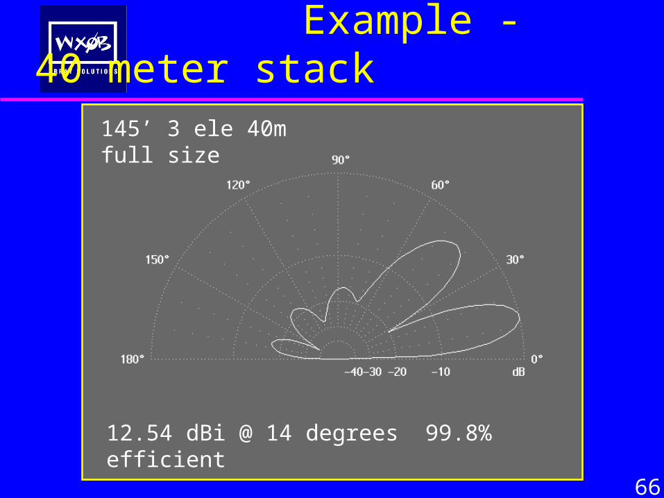
Example - 40 meter stack
66
12.56 dBi @ 13 degrees
145’ 3 ele 40m full size
12.54 dBi @ 14 degrees 99.8% efficient
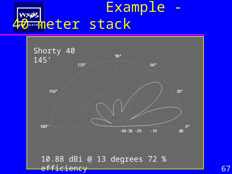
Example - 40 meter stack
67
10.98 dBi @ 13 degrees 72 % efficient
Shorty 40 145’
10.88 dBi @ 13 degrees 72 % efficiency
Shorty 40 145’
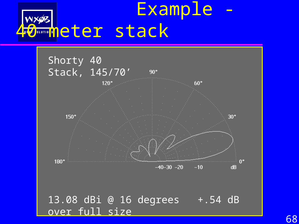
Example - 40 meter stack
68
13.08 dBi @ 16 degrees +.54 dB over full size
Shorty 40 Stack, 145/70’
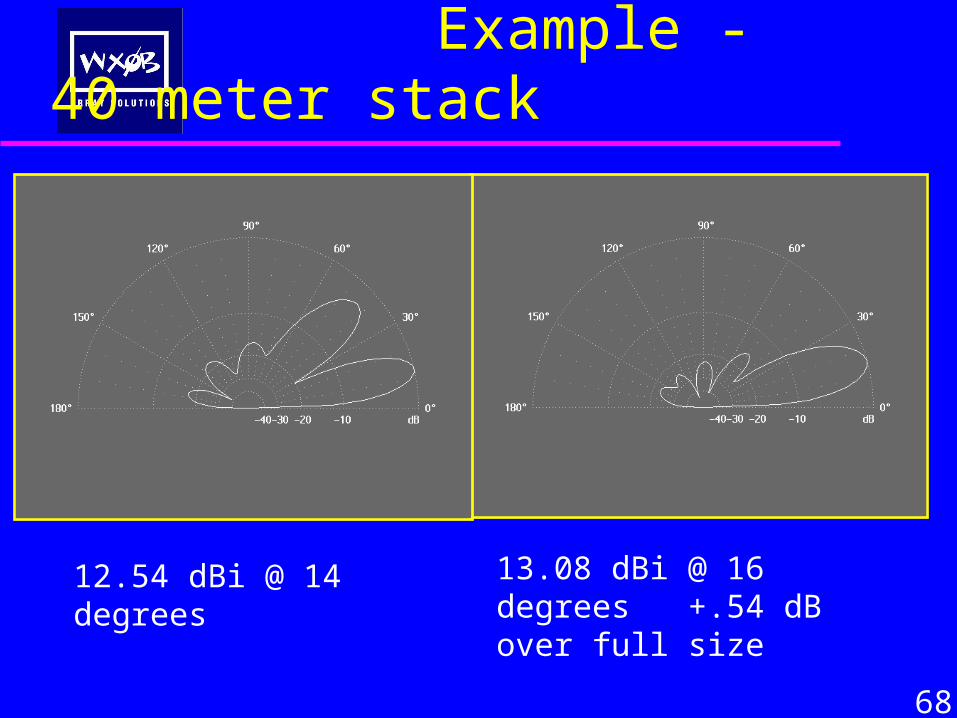
Example - 40 meter stack
68
13.08 dBi @ 16 degrees +.54 dB over full size
12.54 dBi @ 14 degrees
Summary - 40 meter stack
• Shorty 40 stacks are VERY effective in gain and pattern
• Shorty 40 stacks equals or betters a single 3 element full
• A full size 40 stack RULES but a shorty 40 stack is not bad!
69
• Shorty 40 stacks have better pattern than a 3 ele FS beam
• More flexibility, beam in two directions, more angles
• Much easier to maintain
size 40m beam
Other Benefits of Stacking
• Snow, Rain, wind, ionization static can be eliminated or reduced by taking the top antenna out of a stack
• Corona discharge points are on the top beam
70
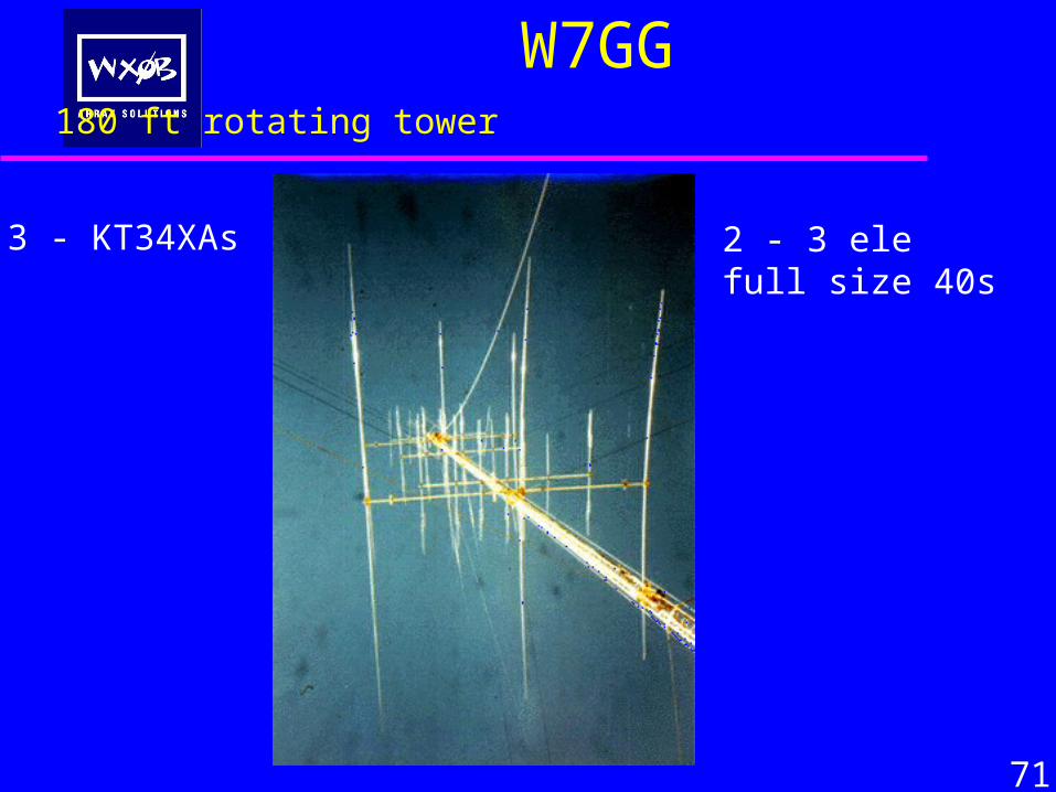
W7GG 180 ft rotating tower
3 - KT34XAs 2 - 3 ele full size 40s
71
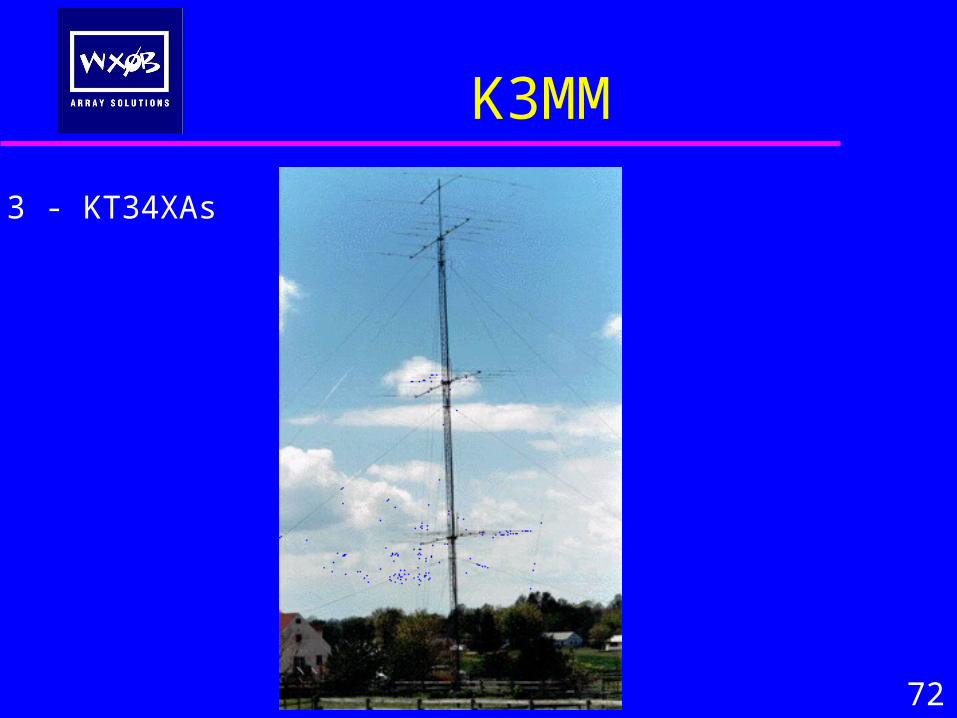
K3MM
3 - KT34XAs
72
73
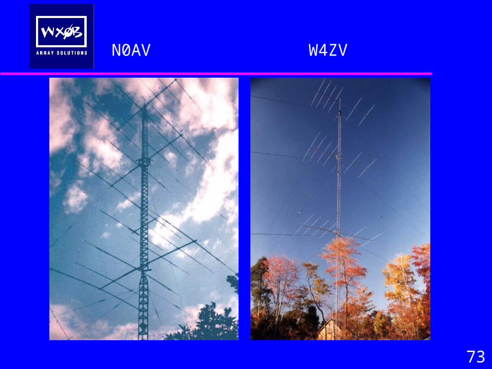
N0AV W4ZV
74
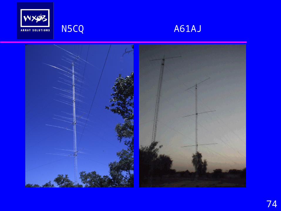
N5CQ A61AJ
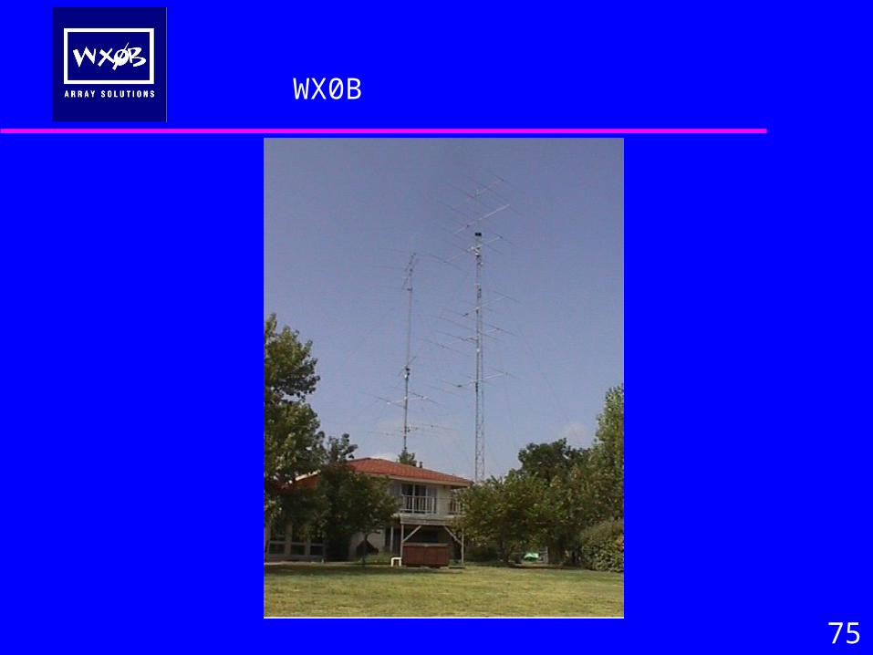
75
WX0B
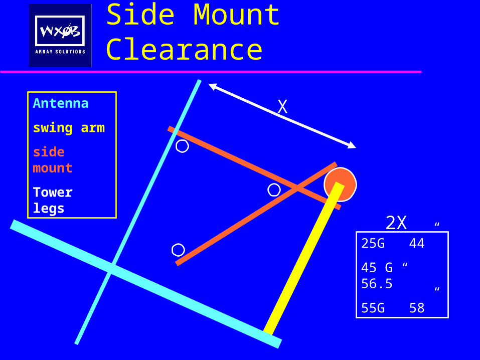
Side Mount Clearance
25G 44”
45 G 56.5”
55G 58”
X
2X
Antenna
swing arm
side mount
Tower legs
A Study of Stacked Arraysof
Yagi-Uda Antennas
Jay Terleski, WX0B
75
QUESTIONS

Thank You All - You’re the Best Customers in this World!


![Theory & Design of the Yagi-Uda Array Aerial [II][L][6]](https://static.fdocuments.in/doc/165x107/55b39d80bb61eb086b8b4580/theory-design-of-the-yagi-uda-array-aerial-iil6.jpg)


![Multi-objective Gain-Impedance Optimization of Yagi-Uda ... · better optimization technique for Yagi-Uda antenna designs, in [30]. In this paper, use of BBO, Blended BBO and NSPSO](https://static.fdocuments.in/doc/165x107/60b31a32028c620c9e76b00e/multi-objective-gain-impedance-optimization-of-yagi-uda-better-optimization.jpg)