A study of forming loads and metal flow characteristics ... · Loughborough University...
170
•
Transcript of A study of forming loads and metal flow characteristics ... · Loughborough University...

Loughborough UniversityInstitutional Repository
A study of forming loads andmetal flow characteristics
during the backwardextrusion of aluminium
This item was submitted to Loughborough University's Institutional Repositoryby the/an author.
Additional Information:
• AMasters Dissertation, submitted in partial fulfilment of the requirementsof the award of Master of Science of Loughborough University.
Metadata Record: https://dspace.lboro.ac.uk/2134/24714
Publisher: c© Malcolm Francis Kimm
Rights: This work is made available according to the conditions of the Cre-ative Commons Attribution-NonCommercial-NoDerivatives 4.0 International(CC BY-NC-ND 4.0) licence. Full details of this licence are available at:https://creativecommons.org/licenses/by-nc-nd/4.0/
Please cite the published version.
. ~
~. . - . -~-"·Ir.:H ,.. ''''/ / .
• 0"-' . 'I > .
. .

\


A STUDY OF FORMING LOADS AND METAL FLOW CHARACTERISTICS
DUR I NG THE BACi<\'If.\RD EXTRUS r Ofj OF ~.LUM I 1'1 IUM
by
Malcolm Francis Kinun, B. Tech.
A Master's Tnesis
Submitted in partial fulfilm",nt of the requirements
for the award of .'
Degree of ~laster of Science of the Loughborough University of Technolo"gy
September 1976
Supervisor: G.F. Modlen, ·M.A., Ph.D., F. I.M. Depar~ment of Engineering Production
© by Malcolm Francis . Kim;n, 1976
Loughborough University Of Technology library
Date Ov.-: . '1, CI.ss A,c. \4:~~ 3 \ /0-;"" N •.

/
CONTENTS -----
LIST OF FIGURES
LIST OF PLATES
LIST OF TABLES
SYNOPSIS
Chapter 1 INTRODUCTION
Chapter 2 LITERATURE REVIEW
ChaEter 3
/
ChaEter 4
2.1 Extrusion Tooling 2.2 Friction and Lubrication 2.3 Can Extrusion 2.4 Visioplasticity and Upper Bound
Techniques 2.5 Metal Flow and Extrusion Defects
EXPERIMENTAL EQUIPMENT
3.1 Extrusion Tool Design 3.1.1 Basic Des.ign Principles 3.1. 2 Indirect Extrusion 3.1. 3 Direct Extrusion 3.1.4 Die Design 3.1.5 Punch Design
3.2 Compression Tool Design 3.3 Ancillary Equipment
EXPERIMENTAL' TECHNIQUES
4 .. 1 Billet Preparation 4.2 .Extrusion Techniques 4.3 Yield Strength Determination
1
3
4
5
7
10
10 11 11 1:3
14
is 15 15 16 17 17 18 20 20
27
27 27 27
/
...
Cha,? te r 5 FOR.L'IJ,NG LOADS
5,1 Genera, 1
ChaEter 6
5.2 External Friction 5.3 Effect of Extrusion Ratio 5.4 Effect of Billet Length 5.5 Effect of Extrusion Direction 5.6 Conical Punch Extrusion 5.7 Nosed Punch Extrusion
~lliTAL FLOW DURING EXTRUSION
6.1 General 6.2 Steady State Flow 6,3 Dead Metal Regions 6.4 Microstructures 6.5 Extrusion Direction 6.6 Incremental Forming 6.7 Flow with Conical Punches 6.8 Flow with Nosed Punches
31
31 31 32 32 33 33 34
50
50 51 52 52 53 53 54 55
Chapter 7 UPPER BOUND SOLUTIONS TO BACKWARD EXTRUSION 68
7.1 The Upper Bound Technique 7.2 The Early Stage of Extrusion 7.3 Use of a Nosed Ram for Extrusion 7.4 Extrusion at the End of the Stroke
Chapter 8 EXTRUSION DEFECTS
8.1 General 8.2 Cavitation 8.3 Internal Cracking 8.4 Shearing
Chapter 9 CONCLUSIONS
9.1 Forming Loads 9.2 Metal Flow 9.3 Extrusion Defects 9.4 Practical Implications
Chapter 10 RECOMMENDATIONS FOR FURTHER WORK
.-
68 69 70 70
76
76 76 77 78
83
83 83 84 85
86

REFERENCES
APPENDIX (1) DIE STRESS CALCULATIONS
(2). EXTRUSION AND COMPRESSION TOOL DESIGN DETAILS AND HEAT TREATHEi~TS
(3) AVITZURS UPPER BOUND SOLUTION
(4) TABULATED DATA
(

/
Fig. No.
3.1
3.2
3.3
3.4
4.1
4.2
5.1
5.2
5.3
5.4
5.5
5.6
5.7
5.8
5.9
5.10
5.11
5.12
5.13 .
5.14
5.15
6.1
6.2
7.1
LlST OF FIGURES
Sectional Diagram of Extrusion Tool
Schematic Representation of Direct and Indirect Extrusion
Extrusion Edge
Simple Compression Tool
Compression Test Curve
True Stress/True Strain Curve for 99% Pure Aluminium
Extrusion Pressure Displacement Characteristics for Various Lubricants
Comparison Between Continuous and Incremental Forming Loads
Punch Load/Displacement Curves For Indirect Extrusion of Billets of H:D=l
Effect of Reduction on Maximum Extrusion Pressure
Effect of Reduction on Punch Stress
Steady Pressure Extrusion Efficiency A . .. s sUI!ung Homogeneous Deformation
Effect of Billet Length on Extrusion Pressure
Effect of Billet Length ob. Maximum Punch Load
Effect of Billet Length on Maximum Ejection
Differing Extrusion Characteristics with Direction
Differing Extrusion Characteristics with Direction
Punch Loads for Partial.Extrusion, l2.7mm Indentation
Punch Load/Displacement Characteristics for Various Punch Angles
Load
Effect of Punch Angle on Maximum Extrusion Pressure for Direct and Indirect Extrusions
Effect of Nose Profile on Maximum Extrusion Load
·Metal Flow Regions
Displacement Vector Diagram Illustrating Metal Flow During Extrusicn Using a Flat Punch
Avitzur's Representation of the Early Stage of Impact Extrusion
-1-
Page No.
21
22
19
23
29
30
36
37
38
39
40
41
42
43
43
44
45
46
47
48
49
50
56
69
J;ig No. Title Page No.
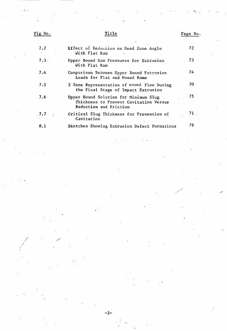
7.2 Effect uf ReuuL:Llull on Dt::au Zone Aflgl~ 7'2. · .. i th Fla tRam
7.3.· Upper Bound ~am Pressures for Extrusion 73 With Flat Ram
7.4 Comparison Bet,·,een Upper Bound Ext!:usion 74 Loads for Flat and Nosed Rams
7.5 2 Zone Representation of sound Flow During 70 the Final Stage of Impact Extrusion
7.6 Upper Bound Solution for Minimum Slug 75 Thickness to Prevent Cavitation Versus Reduction and Friction
.7.7 Critical Slug Thickness for Prevention of 71 Cavitation
8.1 Sketches Showing Extrusion Defect Formations 79
...
-2-
r
Plate No.
3.1
3.2
3.3
3.4
3.5
6.1
6.2
6.3
6.4
6.5
6.6
6.7
6.8
6.9
6.10
6.11
6.12
6.13
6.14
6.15
6.16
6.17
6.18
/ 6.19
8.1
8.2
8.3
8.4
8.5
LIST OF PLATES
Title
Extrusion Tool
Extrusion Punches and Punch Ends
Compression Tool
Sawing Jig
Turning Fixture
Extrusion With Flat Punch R=1.33
Selection of Sectioned Cups
Extrusion With Flat Punch, etched R=1.19
Dead Metal Region, etched, R=1.19
Extrusion With Flat Punch, etched,RR=l.56
Dead Metal Region, etched, R=l.56 .. . Slip Bands in Tube Wall ~ 100
.. .. .. .. .. x 400 .
Collapse of Dead Metal Regions
Incremental Forming R=l.19 .. .. R=1.33 .. " R=1.56 .. .. R=1. 96
./ .-,,-
with Conical Split Sections Punches,
Extrusion with Conical Punch, 8=900,
etched R=l.l9
R=l.l9 .. .. .. .. .. .. .. ..
Comparison Between Billets Nosed rams, R=1.56
Comparison Between Billets Nosed Rams, R=l. 33
8=300
, R=1.19
8=900
, R=1.56
Formed with Flat
Formed with Flat
Split Billet Showing Cavitation~ R=1.33
and
and
.. .. .. .. , etched, R=1.19
Specimens Showing Internal Cracking
Example of Internal Cracking, R=l.96
". .. .. " R=2.78
-3-
Page No.
24
24
25
26
26
57
57
58
58
59
59
60
60
61
62
63
64
65
61
66
66
66
67
67
80
80
81
81
82
<.
". . " . ,
. , ~ -. . . .'
/
Table No .
1
2
3
4
5
6
7
8
9
10
11
12
13
LIST OF TABLES
(Appendix 4)
Title
Compression test data
Re-lubricated compressiun test Jata
Data for indirect flat punch extrusion
" " direct " " "
Homogeneous deformation punch loads'
Loads for l2.7mm punch travel
Effect of punch angle on extrusion load
Effect of billet length on punch and ejection loads
Effect of reduction on dead zone angle wi~h flat punch
Extrusion with nosed profiles
Upper bound ram pressures for extrusion with flat ram
" " " " " " " nosed "
" " solution for prevention of cavitation
-4-

categories, namely cavitation, internal cracking and shearing of the
corner. Cavitation was found to occur when the base thickness becomes
smaller than the wall thickness, which Has also proved theoretically.
Also crackiOlg was found to occur only at large extrusion ratios during
direct extrusion.
Finally, in the light of conclusions drawn from the work,
reconnnendations were made as to suggestions for further work Hhich
could usefully continue the present work.
-6-

· ,,;:;;;:::: , ,
NOMENCLATURE
Chapters 1-6
S Deflection R - Full punch end radius
III End load L - Land length on punch end
9- Length Vd - Die velocity
E ModUlus of elasticity Ln - Naperian logarithm
I Second moment of area ho - Billet height
JI Friction coefficient h Current billet height
R Extrusion ratio 00 - Yield strength in uniaxial tension
H - Billet height m - Friction. factor
D Billet diameter e Punch angle
Vp - Punch velocity· e' - Transition angle
Ve - Extrudate velocity V Velocity of metal flow
E: Longitudinal strain d Punch diameter
r Relieved punch radius
ChaEter 7 and AEEendix III
U
a
r l -
r 2 -
Rf -
Ro -
V
Vf -
h
Punch velocity
Dead zone angle
Radius of dead zone
Radius of zone Il
Ram radius
Chamber radius
Velocity
. Extrudate velocity
Land length
IV
D Depth of punch from top of die cavity
T Can base thickness
e - Angle of base-\o/all intersection
M - Friction factor
h Height of ram
P External pressure on extrudate
PR - Average ram pressure
00.- Yield strength in uniaxial tension
P Extrusion pressure
Y - Mean yield strength
R Extrusion ratio
PMAX -
RI -
R2 -
R3 -or -06 -
b
a
r
E:
Y
1:.
P
Max. extrusion pressure
Outer radius of outer cylinder
Inner radius of inner cylinder
Common cylinder radius
Radial stress
Hoop stress
Constant
Constant
Cylinder radius
Modulus of elasticity
Yield strength
Shear stress
Internal pressure
SYNOPSIS
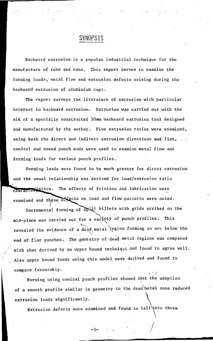
Backward extrusien ,.s a pepular industrial technique fer the
manufacture ef tube and cans. This repert serveS to. examine the
ferming leads, metal flow and extrusien defects arising during the
backward extrusien ef aluminium cup~.
The r.epert surveys. the literature ef extrusien with particular
interest in backward extrusien. Extrusien was carried eut with the
aid. ef a specially censtructed 50mm backward extrusien teel designed
and manufactured by the auther. Five extrusien raties were examined,
using beth the direct and indirect extrusien directiens and flat,
cenical and nesed punch ends were used to. examine metal flew and
ferming leads fer varieus punch prefiles.
Ferming leads were faund to. be much greater fer direct extrusien
usual relatianship was derived fer lead/extrusian ratio.
~~~~~~~~i~c~s. The effects af frictien and lubricatien ~ere
examined and these en lead and flaw patterns were neted. If .
Incremental farming bi~lets with grids scribed en the
mid-plane was. carried eut far a af punch prafiles. This
revealed the evidence
end af flat punches.
af a diad metal "'regian forming an arc belew the ~. , .
The geom etry af de~a. me tal regians was campared
with that derived by an upper baund techniqu~ and feund to. agree well.
Also. upper baund leads using this medel were derived and feund to.
cempare faveurably. ~ , ..:
Farming using cenical punch prefiles she'led t~at. the adaptien
ef a smeath prefile similar in geemetry to. the dead'metal zane reduced
extrusien leads significantly. ~ .
Extrusien defects were examined and feund to. fal~into three \ ,
-5- /

CHAPTER 1
INTRODUCTION

The aim of this thesis is to further the fundamental understanding
of deforrnati.oTl mechanics, as applied to backward extrusion, by
examining forming loads during deformation under a variety of conditions
and more importantly to examine metal flow and defect formation during
the process. Deformation mechanics has reached an advanced stage in
the analyzis of forward extrusion, anJ features prominently in
deformation mechanics li terature. Fon<ard extrusion is probably more
~ easy to analyse because of its more continuous nature. This continuity
is often essential as far as many analytical techniques are concerned,
and many analytical solutions are based upon the steady state region
of the process. Steady states are easily achieved in forward extrusion
but their existance in the more restricted backward extrusion process
is very short-lived, if preserit at all. The present work examines the
extent of the steady state during the process, which is highly
dependant upon such factors as the punch height/diameter ratio and
billet length to be extruded. Punch lengths are obviously limited
due to the possibility of failure by buckling, this limits the
duration of the process to relatively short times.
An extrusion tool was specially designed and constructed to
carry out the present work, having a die diameter of 50mrn and a
maximum press'~re capacity of 1000 N/mm2 • Five extrusion ratios were
produced with punches varying from 20 to 40mm dia. in 5rnm steps.
The tool was found to perform most satisfactorily in both direct and
indirect directions, enabling the differences between the processes
to be observed in terms of load, metal flow and defect formation. A
compression tool was ·also designed to establish the yield strength of
the material. The experimental material used was annealed 99% pure
aluminium, although the die was designed to cater for higher strength
materials in consideration of possible further work.
-7-
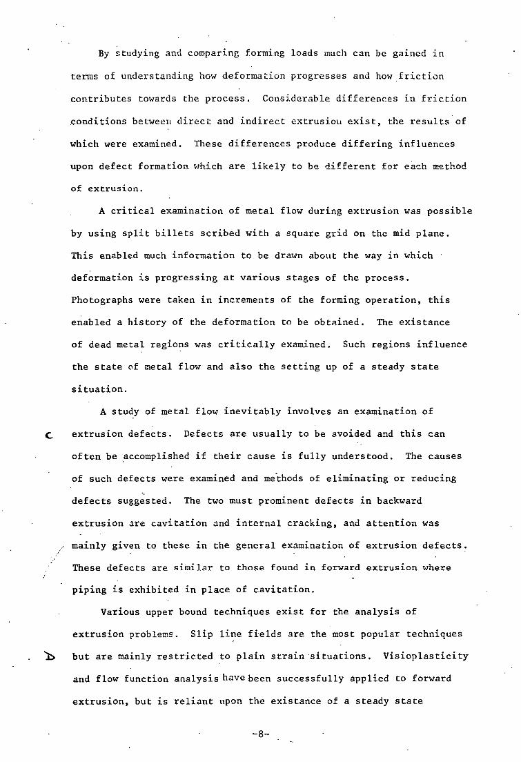
By studying and comparing forming loads much can be gained in
terms of understanding how deformation progresses and how frictiun
contributes towards the process. Considerable differences in friction
.conditions betweell direct and indirect extrusioll exist, the results' of
which were examined. These differences produce differing influences
upon defect formation Hhich are likely to be different for ea"-h lI!ethod
of extrusion.
A critical examination of metal flow during extrusion was possible
by using split billets scribed with a square grid on the mid plane.
This enabled much information to be drawn about the way in which
deformation is progressing at various stages of the process.
Photographs were taken in increments of the forming operation, this
enabled a history of the deformation to be obtained. The existance
of dead metal regions was critically examined. Such regions influence
the state of metal flow and also the setting up of a steady state
situation.
A study of metal flow inevitably involves an examination of
C extrusion defects. Defectz are usually to be avoided and this can
often be ,accomplished if their cause is fully unders tood. The causes
of such defects were examined and me'thods of eliminating or reducing
defects suggested. The two must prominent defects in backward
extrusion are cavitation and internal cracking, and attention was
mainly given to these in the general examination of extrusion defects.
These defects are similar to those found in forward extrusion where
piping is exhibited in place of cavitation,
Various upper bound techniques exist for the analysis of
extrusion problems, Slip line fields are the most popular techniques
b but are mainly restric.ted to plain strain ·situations. Visioplasticity
and flow function analysis have been successfully applied to forward
extrusion, but is reliant upon the existance of a steady state
-8-

i
· ..•..
situation; the approach yields the complete solution in terms of
strain rates, strains and streRses. It is hoped that the present
work will serve as a feasibility study for the possibility of applying
such a technique t·) backward extrusion. The upper bound solution
. . (1) proposed by AV~t2V~ was used to analyse the process. This solution
splits the body into a number of deformation zones, the boundaries of
which were fonnd to be accurately predicted. The model was used to
establish upper cound loads and also to predict the onset of defect
formation.
Finally in the light of conclusions drawn from the work,
recommendations were made for possible further work which could
usefully continue the present study.
-9-

CHAPTER 2
LITERATURE REVIEI1

2.1 EXTRUSION TOOLING
The design of extrusion tooling and choice and heat treatment of
of tool materials iR of flJ!ldam£'.!ltal i!!!portE!n~e to any study in
extrusion. The extrusion ?rocess subjects tooling to very high
pressures and particular care is needed to ensure efficient and long
life tooling. Extrusion punches in backwar.d extrusion are of
particular importance in this respect as they are subjected to
particularly high preasures.
A variety of suitable tool materials exist for application to
extrusion:tooling. Everhart(2J suggests that a survey of extrusion
of aluminium and aluminium alloys indicates the use of 12% chromium
__ .steels favoured -both for punches and die, he also outlines a number
of different alloys proposed by other workers. A number of guides to
the selection of tool steels for extrusion are in publication(3) and
the use of carbide tools are also surveyed (4) •
Heat treatment of extrusion tooling steels is of great import.ance
if reliable re5ults are to be attained. A survey of suitable treatments
is outlined in a P.E.R.A. report(5) in which a variety of tool steels
and treatments for extrusion punches are examined.
A variety of designs exist for both dies and punches. Punch
failure due to change of punch section is common along with other
defects(6). Morgar/7J has conducted a thorough investigation into
.-- punch profiles and their effect on resulting i!lternal stress
concentration using photoelastic stress analysis; here the use of non-
composite punches is recommended. A variety of punch profiles and die
b f 'l . d' P R A (8) h ff f ase pro 1 es are exam~ne 1n a .E ••. report on tee ects 0
tool geometry on back,·,ard extrusion. A hemispherical punch end profile
is found to produce a considerably lower punch load than a flat punch.
Concerning punch relief, a survey by Everhart(9J reveals how punch end
-10-
geometry affects ext:rusi.on load and performance for a variety of
experimental materials; a diametral clearance of 0.004 inch is
recommended for. aluminium by a number. of .. orkers as being the optimum
value.
Concerning die design, this is relatively straight for..ard in
backward extrusion as the profiie is relatively simple. Compound rings
of tool steel are usually adapted to cope with the high stresses.
Literature on die design is usually found to apply to for..ard extrusion,
but some more general paper$ exist(lO). Die design in for..ard extrusion
has reached a sophisticated level with a number of theoretical design
. (11 12) (12) techniques in ex~stance ' . Shabaik's paper uses the results
of visioplasticity analysis of for..ard extrusion to examine die
performance under a variety of·friction conditions.
2.2 .FRICTION AND LUBRICATION
Friction and lubrication are important factors in any type of
extrusion. An excellent publication by Schey(13) looks at all aspects
of friction and lubrication as applied to deformation processes in
general. A wider variety of lubricants are recommended by a number
of workers, although lanoline, tallow and waxes seem to produce best
results with aluminium. The use of lanoline with aluminium is reputed
to give a friction coefficient of 11= 0.02.
• (lO) Watk~ns used sulphonated tallow but found it inefficient at
slow speeds. Lanolin, tallow, various soaps, and graphite in tallow
were found to give. better performance in terms of maximum extrusion
pressure.
2.3 CAN EXTRUSION
Much more attention is given to for..ard extrusion than backward
-11-
extrusion and relatively fe" papers are to be found on detail.ed
experiments in backward extrusion. Hany reports on backHard extrusion
relate te cxtru~icn of" :JtcclG but a. n:.;mbcr do deal .... ?ith aluminium
extrusion.
(8) A.P.E.R.A. report deals with the effect of punch and die
geometry on backward extrusion. The report examines 11 different
punch profiles and· their effect on metal fl0\01 and extrusion load. Five
·different die base profiles are also examined. Another paper <:oncerned
. h b k d . f l' b k' (14) W1t ac war extrus10n 0 stee 1S y Wat ~ns . This paper examines
a variety of combinations of forward and backward extrusions, and the
differences in terms of pressure charactersitics between the different
. types of extrusion.
The effect of ram speed in the extrusion of lead and aluminium is
(15) examined by Asharoft . The effect of billet length, diameter ratio
d b / 11 1 · k " . d' d '1 b C--' (16) an ase wa tl~C ness rat1Q 1S exam1ne 1n et31 y ~'uuen .
This report examines in detail the aforementioned topics. In conclusion,
the report finds that the final base/wall thickness ratio profoundly
influences the extrusion pressure, particularly in operations at the
longer extrusion ratios (R>2.0), when pressures greater than those
r.ormally defi~ed as the maximum pressures may be attained, if base/wall
thickness ratios less than 0.5 are attempted. The onset of cavitation
is· also examined.
Extrusion pressures are predicted for backward extrusion within
. . 1 b K 7. __ (17) . I' h f . a very pract1ca paper y aSr~' ,1n W11C a range 0 extrus10n
ratios between 1.28 and 2.72 are examined.
A very thorough historical survey of extrusion techniques has
been . (18)
pub11shed by Pearson • This book also introduces many other
aspects concerning extrusion techniques and ·characteristics.
-12-

/
2.4 VI.SIOPLASTICITY .AND UFl'ER BOUND TECHNIQUES
Among a variety of upper bound techniques in existance for the
solution of extrusion problems visioplasticity has developed as one
of the more recent and most successful technique. Here, the billet
is scribed with a grid on the mid-plane so that flow lines during
steady state flol-1 can be monitored. These are used to set up a
mathematical model constructed along the existing flow lines which
eventually reveals the complete solution in terms of stress and strain
fields and their distributions. The founders of the technique in its
present form, Shabaik and Thomsen have produced a number of papers in
which the technique is applied to forward extrusion through conical
dies. The technique is outlined in detail in two papers by Lambert
nd K b h ·(]9,20) d 1" h h' . a 0 ayas 0 an computer app ~cat~on to t.e tec n~que ~s
outlined by Shabaik(21,22). A further paper by Shabaik(23) pays
particular attention to friction coefficients during the extrusion of
aluminium. Another paper by Medrano and G1;ZU.9 (24) outlines the
(25) technique in a slightly different manner. A paper by Farag
illustrates the solutions in terms of plots 'of stress, strain and
temperature profiles within the billet.
The only .. application of visioplasticity to backward extrusion is
by Mehta(26). This thesis examines backward extrusion using conical
punches. The results are interesting but the data is not smoothed
and therefore does not allow· easy comparison with the present work.
Apart from visioplasticity a number of techniques exist for
solution of extrusion problems by the upper bound technique. Kudbs(27)
technique of defining velocity fields by splitting the body into zones
is well known. This technique is enlarged and applied to extrusion by
u b h·(28,29) A't ' h' (30,31). .. 11 . d' AO ayas 0 • Vo zur s tec n~que 15 cr~t~ca y exam~ne 1n
this thesis and is similar to the Kudds technique of analysis.
-13-

Other techniques of analysis are outlined by Thomsen et aZ(32)
and a survey of slip line J;ields i"s produced by Johnson(33) although
this is restricted to plane strain deformation.
2.5 METAL FLOW AND EXTRUSION DEFECTS
The study of metal flow and extrusion defects forms a major part
of this thesis. Metal flow is analysed by examining the deformation of
scribed grids on the mid-plane of the billet. This is a commonly used
method of analysing forward extrusion but it has been sca~cely used as
a tool for the analysis of backward extrusion and no literature was
found which analysed flow during backward extrusion in detail.
The P.E.R.A. and N.E.L. reports previously mentioned deal with
extrusion defects as a part of a general survey of backward extrusion.
The study of metal flow in these reports is restricted to the examination
of etched specimens which is a limited technique.
-14-
CHAPTER 3
EXPERIMENTAL EQUIPMENT
.'
/'
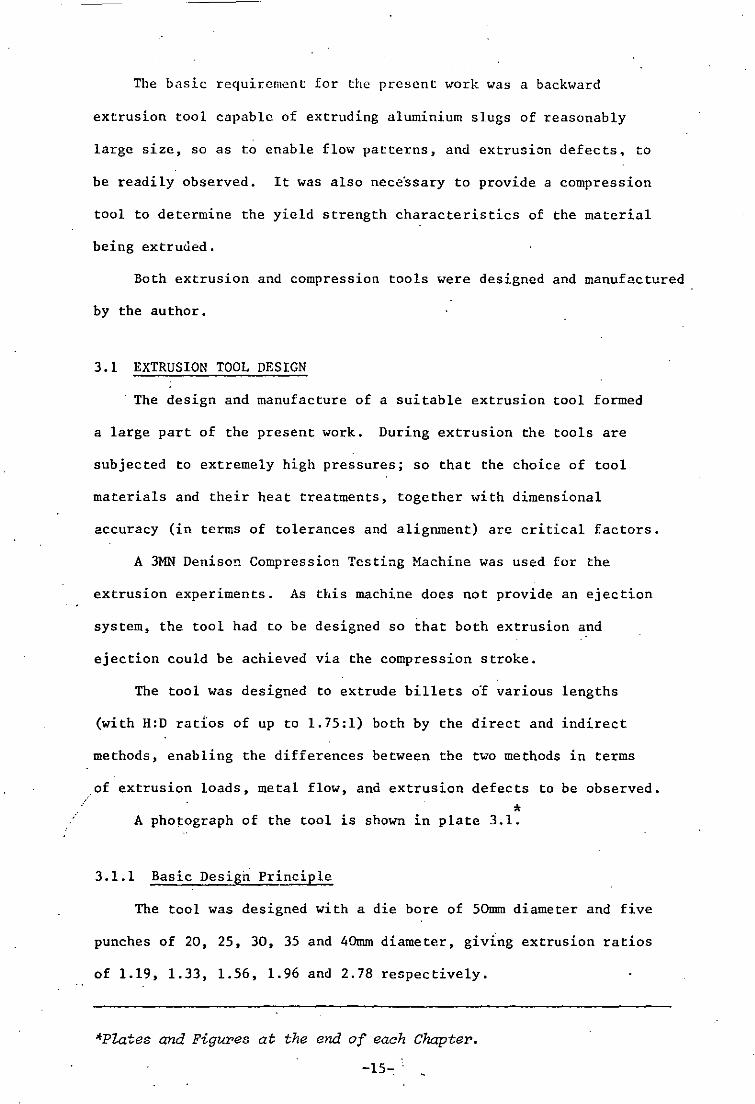
The basic requirement for the present work was a backward
extrusion tool capable of extruding aluminium slugs of reasonably
large size, so as to enable flow patterns, and extrusion defects. to
be readily observed. It was also neceOssary to provide a compression
tool to determine the yield strength characteristics of the material
being extruued.
Both extrusion and compression tools were designed and manufactured
by the author.
3.1 EXTRUSION TOOL DESIGN
The design and manufacture of a suitable extrusion tool formed
a large part of the present work. During extrusion the tools are
subjected to extremely high pressures; so that the choice of tool
materials and their heat treatments, together with dimensional
accuracy (in terms of tolerances and alignment) are critical factors.
A 3MN Denison Compression Testing Machine was used for the
extrusion experiments. As this machine does not provide an ejection
system, the tool had to be designed so that both extrusion and
ejection could be achieved via the compression stroke.
The tool was designed to extrude billets oOf various lengths
(with H:D rat10s of up to 1.75:1) both by the direct and indirect
methods, enabling the differences between the two methods in terms
of extrusion loads, metal flow, and extrusion defects to be observed.
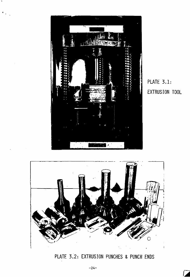
* A photograph of the tool is shown in plate 3.1.
3.1.1 Basic Design Principle
The tool was designed with a die bore of 50mrn diameter and five
punches of 20, 25, 30, 35 and 40mrn diameter, givlng extrusion ratios
of 1.19, 1.33, 1.56, 1.96 and 2.78 respectively.
*P~tes and Figures at the end of each Chapter.
-15-:

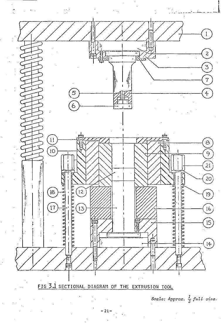
Wi th reference to the sec tiona 1 diagram, (Fig. 3.1) the die and
punch assembly were mounted in a bolster to maintain accurate
alignment. The die ~·,as designed in the form of a c.ompound cylinder
(8,9)* mounted within a die housing (10). The die assembly waS
aligned with the lower punch (13) by two pillars (17), and was
supported on springs to enable the support (16) to be easily removed.
During indirect extrusion the die assembly is securely clamped
against the support, whieh is removed for ejection. The die insert
(12), enables the die depth to be varied, and pressure pads (2.14)
serve to ;distribute the high pressures from the upper and lower
punches.
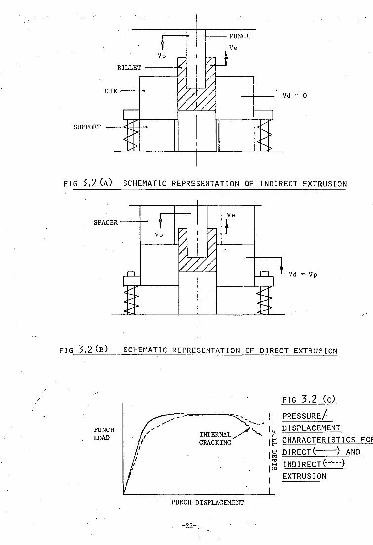
3.1.2 Indirect Extrusion
Fig. 3.2 illustrates the fundamental differences between direct
and indirect extrusion. In indirect extrusion the die is rigidly
held against the support, and the punch advances into the billet
with velocity Vp. The emerging product flows in the opposite
direction to the punch with velocity Ve, which is obviously
dependent on the punch velocity and extrusion ratio as Ve = Vp(l-R).
To eject the extrudate the support is removed, and a spacer
placed on top of the die, so that compression causes the die to lower
until the extrudate is effectively pushed out of the die.
Depending upon the depth of punch indentation and extrusion
ratio, the punch sometimes sticks in the die prior to ejection; in
which case the punch is detached from the boister prior to ejection,
and the punch and extrudate are ejected together.
*Figures in brackets refer to details in Fig. 3.1.
-16-

3.1.3 Direct Extrusion
For direct extrusion, Fig. 3.2 , the support is removed and a
spacer placed between the top of the die and the bolster. The
spring loaded die is moved with the same velocity as the punch Vp,
relative to the stationary lower punch. This is effectively the
same as keeping the die and punch stationary, and performing the
operation by advancing the lower punch, as is common in forward
extrusion of rods.
Ejection is achieved in a similar manner as indirect extrusion.
Unless otherwise stated, all extrusions were performed by the" indirect
method.
3.1.4 Die Design
As previously stated, the stresses arising in extrusion tools
are usually very large, the die in particular is often subjected to
pressures which can exceed the strength of the die material; this
can however be overcome as will be discussed.
For the purpose of calculating die stresses, the extrusion
pressure is assumed to be distributed hydros~atically, so that the
extrusion pressure produces an equivalent radialcompressive force in
the die. This force results in the setting up of hoop stresses, the
greatest stress occuring at the die bore, thu~ establishing a
"" criterion for maximum permissible die pressure. If the die is
considered to be a thick cylinder Lames equations allow these
E stresses to be calculated.
Where the maximum hoop stresses exceed the strength of the die
material, the die can be constructed in the form of compound rings.
The outer ring puts the inner one in compression, thus lowering the
hoop stress to an acc;eptable level; the outer ring is obviously in
-17-"
tension, but as the hoop stress reduces "ith increasing diameter,
the outer ring may also assume an acceptable level of maximum stress.
The level of interference betl'leen compound rings, the number of
rings and their diameters and materials all influence the distribution
of die stresses, which must lie within safe working limits.
For the present work a compound die consisting of two rings was
designed to withstand a maximum die pressure of 1000 N/mm2; this
pressure being estimated as suitable for the extrusion of materials
with. mean yield strengths'of up to 460 N/mm2 , thus allowing for the
extrusion of hard aluminium alloys in consideration of further work.
The complete die stress calculations are given in Appendix (1),
the maximum shear stress criterion being used to establish safe
working stresses. The die was constructed of two ~ings, the inner
one of die steel and the outer one of EN25. The interference fit
of 0.48mm on a 110mm diameter was accomplished thermally by fitting
the outer r1ng immediately after withdrawal from the annealing
furnace. The inner ring was also cooled to provide a larger safety
margin.
After fitting the two rings the die surfaces were re-ground and
the die bore ground and honed to ensure accuracy of alignment. A
F. surface finish of 0,1 ~/mm was achieved at the die bore.
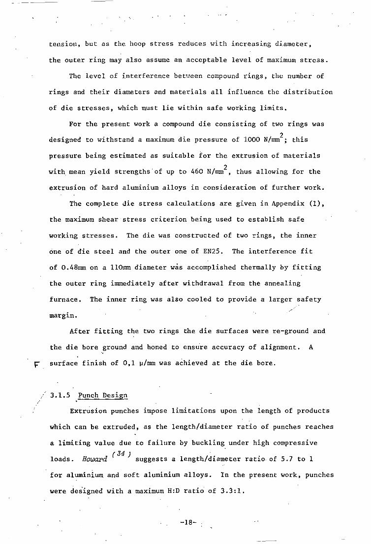
3.1.5 Punch Design
Extrusion punches impose limitations upon the length of products
which can be extruded, as the length/diameter ratio of punches reaches
a limiting value due to failure by buckling under high compressive
loads. (J4 )
Howard suggests a length/diameter ratio. of 5.7 to 1
for aluminium and soft aluminium alloys. In the present work, punches
were des'igned with a maximum H:D ratio of 3.3:1.
-18-
Punch shape and construction influence the distribution and
concentration of stresses. An extensive study of the stress
G distribution in punches or varying shapes has been conducted by
( 7 ) Morgan , using photoelastic strese analysis. This "ould
strongly oppose the use of compound punches "ith shrunken heads,
which would at first sight appear to be an economical way of
t-I locating various sizes of punches. Punches used in the present work
were constructed from one piece, "with large blending shoulder radii,
and were found to perform quite satisfactorily.
Whe~ extruding steel, punch stresses" reach the limiting
capacity of the tool materials. As stresses encountered when
extruding aluminium are not so high it was possible to produce
punches with differing end adaptors having different profiles. This
enabled studies to be made using flat, conical and nosed ends to be
made without the necessity for a large number of individual punches.
The main body of the punch was made from die steel and the ends,
which are subjected to more arduous conditions, from high speed
steel.
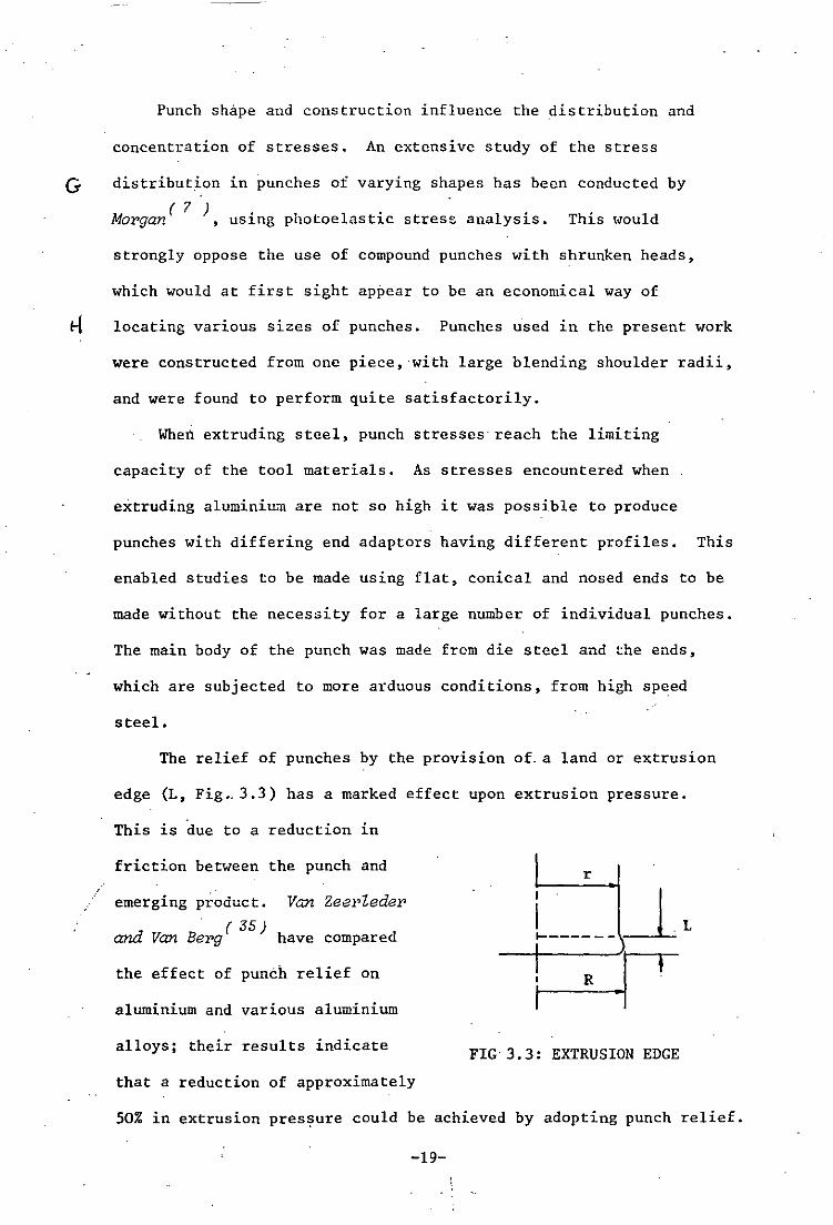
The relief of punches by the provision of. a land or extrusion
edge (L, Fig •. 3.3) has a marked effect upon extrusion pressure.
This is due to a reduction in
friction between the punch and
emerging product. Van Zeel,Zeder
" (35) and Van Berg have compared
the effect of punch relief on
aluminium and various aluminium
alloys; their results indicate
that a reduction of approximately
r
FIG 3.3: EXTRUSION EDGE
50% in extrusion pressure could be achieved by adopting punch relief.
-19-

The extent of punch relief u usually of the order of O,lmm on
diameter, and this was used for all punches.
The extrusion punches together "ith a selection of punch ends
are. shown in plate 3.2.
Complete detail drawings for the extrusion tool, together with
heat treatments are to be found in Appendix 11.
3.2 COMPRESSION TOOL DESIGN
Extrusion pressure is often normalized by taking into account
the yield strength of the material being extruded. Yield strength
is also requir~d in upper bound calculations of extrusion pressure.
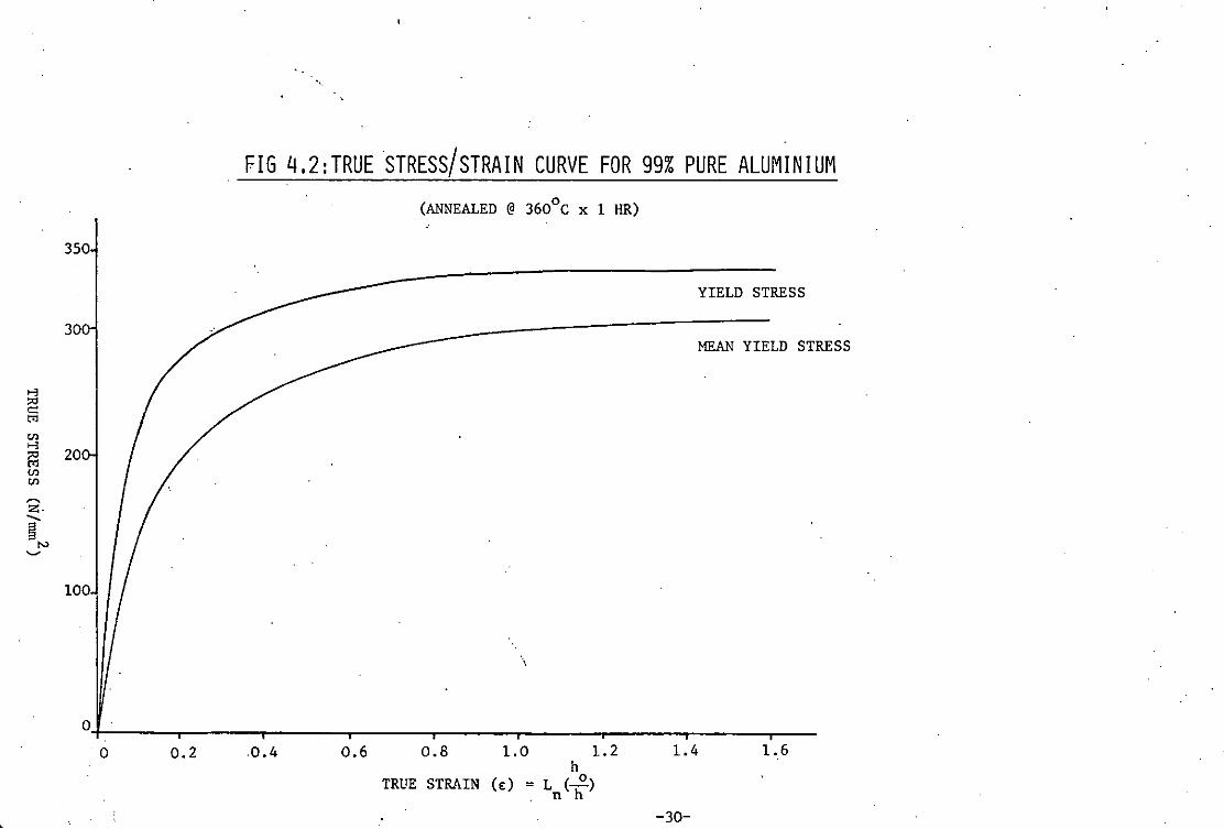
A true stress true strain curve relates yield strength for various
strains, and these data are readily obtained from a simple
compression test.
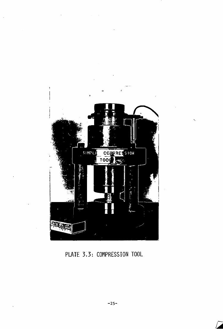
The simple compression tool designed and manufactured for these
tests is illustrated in Fig. 3.4 and plate 3.3. It consists simply
of two anvils, the lower one fixed and the upper one attached to a
punch whereby pressure is applied. Both anvils were lapped to a
I surface finish of 0, I ll/mm to minimise frictional effects. An
alignment pad is allowed to float and thus take up ·any mis-alignment
in the press, ensuring parallel faces between the anvils.
Complete detail drawings of the compression tool, together with
heat treatments are to be found in Appendix 11.
3.3 ANCILLARY EQUIPMENT
To assist in the manufacture of the extrusion billets as will
be described in Chapter 4, it was necessary to manufacture two
tooling aids; a sawing J1g and turning fixture, these are illustrated
in plates 3.4 and 3.5.
-20-
j ... ' . .' . 1 . . - .~ .. ---- .... -~-- .......... - --- "--'
'----------1 3 ,
, ~
. I
'~ ,I' ~l
" 'I !' :" :! I'
1 I i I ( ,. :L .!; ,. .,. i!
j' , .. I
F I G3.l SECT! ONAl D I AGRAf.l OF THE EXTRUS I ON TOOL
8aaZe: Approx. J fUU size.
- 21-
!
· ..
-j--PUNCIl
Ve Vp
BILLET ---.Jt;
DIE --1-Vd ; 0
SUPPORT --H+-
FIG 3.2 CA) SCHEMATIC REPRESENTATION OF INDIRECT EXTRUSION
Ve SPACER---f-
Vp
Vd ; Vp
FIG 3.2 CB) SCHEMATIC REPRESEtHATION OF DIRECT EXTRUSION
PUNCH LOAD INTERNAL
CRACKING
PUNCH DISPLACEHENT
-22-
FIG 3.2 Cc)
PRESSURE! I." DISPLACEMENT I~ CHARACTERISTICS FOR I~ DIRECT( ) AND I~INDIRECT(-----)
I EXTRUSION

, , "
.', . . ,
" .
• "
.. "
•
~Ii-, -- ----I"
~~7=~~------~ Co,
',' ,I ~
FIG 3.4 SH1PLE COHPRESSIOrl TOOL SHO\'IN IN HALF SECTION
2 Scale: Approx - full size. J
-23-
'or
•
PLATE 3.1:
EXTRUSION TOOL
!
"'---'-J
I
. )
o
PLATE 3.2: EXTRUSION PUNCHES & PUNCH ENDS
-24-
o ,
o
PLATE 3.3: COMPRESSION TOOL
-25-

, PLATE 3.4: SAWING JIG
.,
. ,..-r rv----......._ ,"
PLATE 3.5: ,TURN.ING -FIXTURE < • - -0. __ _
-26-

CHAPTER 4
EXPERIMENTAL TECHNIQUES
. (
( \

·'
4.1 BILLET PREPARATION
The material used for experimental tests was 99% pure aluminium,
1" ss 1476 EIr.N, which was supplied .!ith a diameter of 27; Prior to
. 0 use, the material was annealed at 360 C x 1 hr., with a resulting
:r hardness of 63 HV.
As a large number of split billets were required, their
manufacture was accomplished with the aid of two tooling aids. The
supplied bar was firstly turned to fit· a sawing jig (plate 4.1) in
which each billet was split across the diameter. After machining
each face, these halves were then re-turned in a turning fixture
(plate 4.2) to the correct diameter. A diametral clearance of 0,13
was left between the diameter of the billet and die bore to allow
for lubrication coating.
Where split billets were to be used, a 2.5mm square grid of
parallel lines was scribed on one half of the billet, thus allowing
flow patterns to be observed.
All billets were lubricated with a solution of Abryl wax
immersed in trichlorethylene,- which left a thin coating of wax
K lubricant on the billet surface.
4.2 EXTRUSION TECHNIQUES
The extrusion tool was found to perform admirably and a number
of tests were completed using a variety of punch profiles by both
the direct and indirect methods. Various heights of billet were
used and split as. well as full billets were used. In all extrusions
the speed of extrusion was approximately Imm/sec (punch advance).
4.3 YIELD STRENGTH DETERMINATION
To determine the yield strength of a material a mmpressio~ test
-27-

is usually carried out as this allows for much greater deformation
than in a simple tensile test.
A significant error can arise during such tests by the
introduction of friction between the slug being tested and the
anvils of the compressi.on tool. This can lead to an increased load
for a given amount of deformation. The frictional effect can be
reduced by efficient lubrication which can be repeatedly applied
between loads in an incremental test. In some tests, a height to
diameter ratio of 1 is maintained by re-machining after increments
of compression, this reduces the 'barreling' effect and maintains a
bi-axial stress state.
In the present work the specimens were. re-lubricated at intervals
which produced satisfactory results. The same wax lubricant as for
extrusion was used, although several tests were made using a different
set of lubricants. The load displacement curve and yield strength
curves are shown in Figs. 4.1 and 4 •. 2.
-28-

500
400
5 > '" 300 ~
2 ~
200
100
.'
FIG 4.1 COMPRESS ION TEST CURVE
CONTINUOUS COMPRESSION
• RE-LUBRICATED COMPRESSION
I 5
SPECIMEN DIMENSIONS:
19.05MM DIA x 19.05MH
10
TRAVEL (MM)
-29-
'.
15
>-l ::<l c::: t'l
'" >-l
1:l '" '" ~
z· ..... § '" ~
"
FIG 4.2:TRUESTRESS/STRAIN CURVE FOR 99% PURE ALUMINIUM (ANNEALED @ 360°C x 1 HR)
350
YIELD STRESS
30 ----------------------~~:A~N::YI:ELD STRESS
20
100
\
O+------r----~------~----_r----_,------~----_r----_,---'0 0.2 .0.4 0.6 0.8 1.0 1..2
h TRUE STRAIN (E) : L (~)
. n h
1.4 1.6
-30-

.. "'-
CHAPTER 5
FORMING LOADS
..•.
'.
5.1 GENERAL
The load required for forming arises due to the overcoming of
various forcc.~; namely she.ar and friction losses, awl the po\ver of
internal deformation. These vary according to the geometry and
nature of the process. Extrusion forces can be most readily reduced
by reductions in friction and variation in the process geometry, for
example in backwa_rd extrusion by the alteration of punch profile.
Both direct and indirect extrusion >laS examined at several values
of extrusion ratio, using differing billet lengths. Also the effect
of using conical and nosed punch profiles was noted, as to its effect
on metal flow characteristics and extrusion loads.
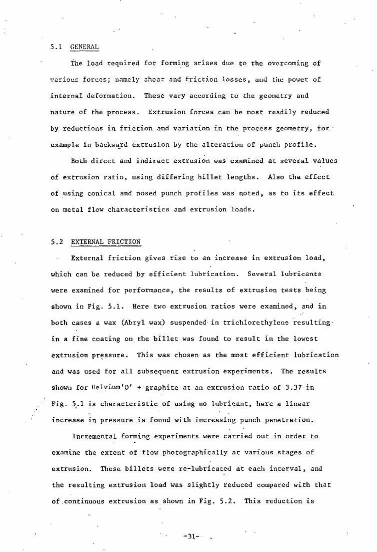
5.2 EXTERNAL FRICTION
External friction gives rise to an increase in extrusion load,
which can be reduced by efficient lubrication. Several lubricants
were examined for performance, the results of extrusion tests being
shown in Fig. 5.1. Here two extrusion ratios were examined, and in
both cases a wax (Abryl wax) suspended'1n trichlorethylene 'resulting'
in a fine coating on the billet was found to result in the lowest
extrusion pressure. This was chosen as the most efficient lubrication
and was used for all subsequent extrusion experiments. The results
shown for Helvium'O' + graphite at an extrusion ratio of 3.37 in
Fig. 5 .• 1 is characteristic of using no lubricant, here a linear
increase in pressure is found with increasing punch penetration.
Incremental forming experiments were carried out in order to
examine the extent of flow photographically at various stages of
extrusion. These billets were re-lubricated at each ' interval, and
the resulting extrusion load was slightly reduced compared with that
of continuous extrusion as shown in Fig. 5.2. This reduction is
-31-

.. ".
•
/
L
attributed to a reduction in friction largely due to more efficient
lubrication.
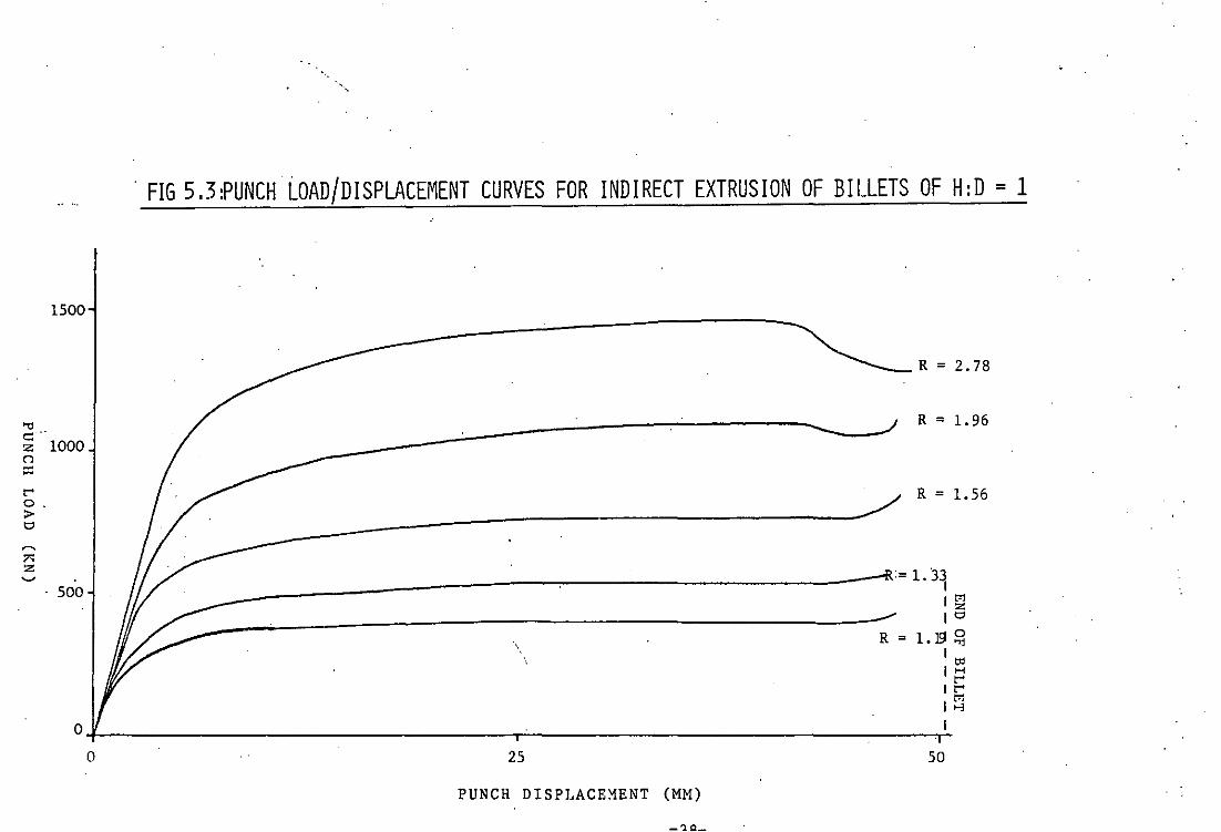
5.3 EFFECT OF EXTRUSION RATIO
Obviously as the extrusion ratio increases the load required to
deform an increasing amount of material increases as illustrated in
Fig. 5.3, which shows the load/displacement c3a~acteristics for five
extrusion ratios.
The effect of reduction on maXLmum extrusion pressure is shown
in Fig. 5.4, the maximum pressure being apparently proportional to
the log. of the extrusion ratio, this is a common finding in extrusion
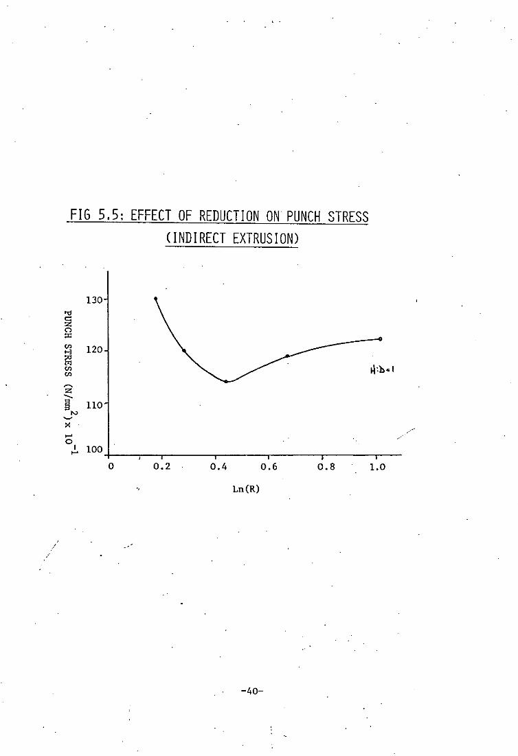
load characteristics. The punch stress varies with extrusion ratio
as shown in Fig. 5.5. As can be seen the punch stress has a minimum
at an extrusion ratio of about 2.8.
If homogeneous deformation is assumed, the steady state
extrusion efficiency can be derived, which increases with extrusion
ratio (Fig. 5.6) reaching a maximum of 40% at the highest extrusinn
ratio. The results compare favourably with those of other workers.
5.4 EFFECT OF BILLET LENGTH
Billet length has a pronounced effect both on metal flow and
extrusion pressure. Punch load/displacement characteristics for
various billet lengths are shown in Fig. 5.7, and in Fig. 5.8 the
maximum punch load is plotted against billet length for a particular
extrusion ratio •. It is apparent that as billet length increases so
the maximum extrusion load increases due to the deforming of a
larger amount of material. Also, as billet length increases so does
the ejection load, in an almost linear fashion as shown in Fig. 5.9.
-32-
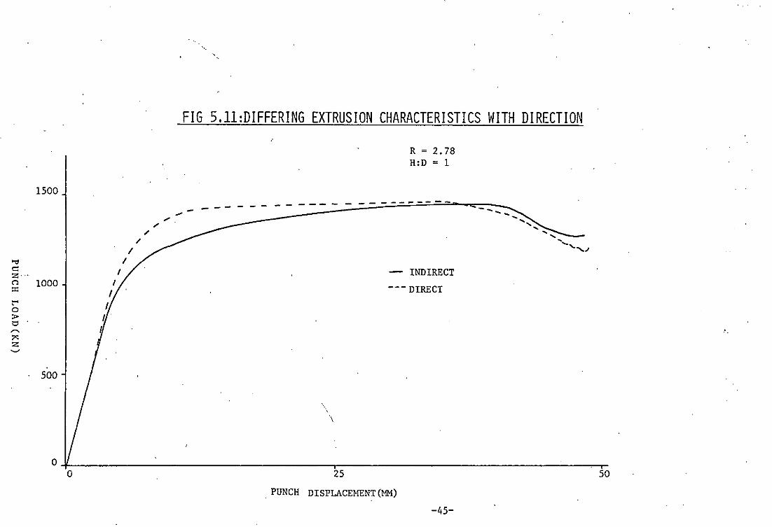
5.5 EFFECT OF EXTRUSION DIlmr.nON
Extrusion experiments were carried out by both the direct and
indirect methods. The fundamental difference between these two
methods is described in Fig. 3.2. In'direct extrusion the whole of
the billet is moved relative to the die during the extrusion process,
whereas in indirect extrusion the billet remains stationary relative
to the die. As the billet is under pressure in direct extrusiou
whilst it is moved relative to the die, an extra load is encountered
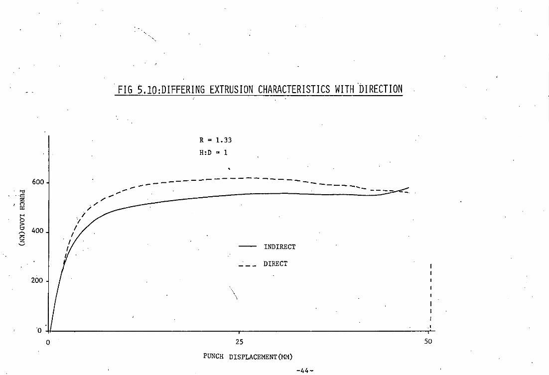
r1 as compared with indirect extrusion. This gives rise to an increase
in overa~l extrusion load. As can be seen from the load/displacement
characteristics in Figs. 5.10 and 5.11 the loads for both direct and
indirect extrusion remain substantially constant once a peak has been
reached, but the level for direct extrusion is greater by up to ·10%
this being due to the additional friction encountered. This is found
to prevail at all extrusion ratios (Fig. 5.12) where the maximum
punch loads for a range of extrusion ratios are plotted for both
methods of extrusion.
The effect of extrusion direction on metal flow and extrusion
defects will be discussed in subsequent chapters.
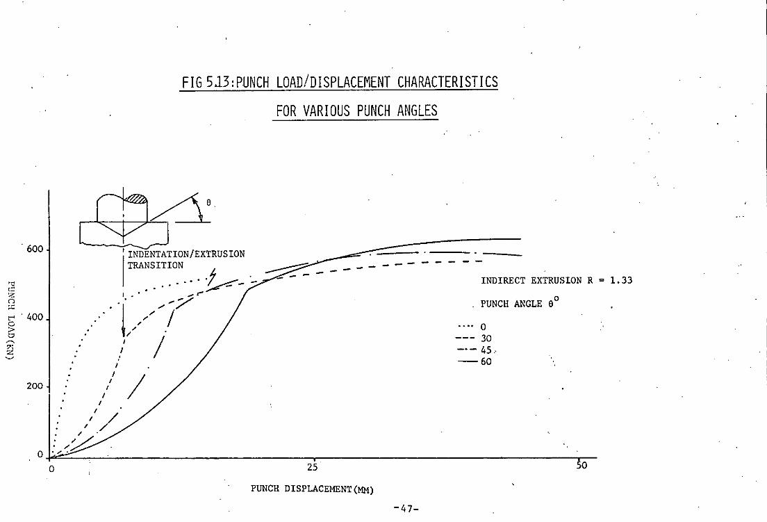
5.6 CONICAL PUNCH EXTRUSION
A series of punch ends were designed with conical. profiles to
examine the effect of punch core angle on extrusion load. The punch
load/displacement characteristics, showing the effect of angle on
punch load, are plotted in Fig. 5.13. A transition in' these.
characteristic curves can be seen as the punch fully enters the
billet, this transition being that from an operation of indentation
to one of extrusion. It is apparent for this figure that as the
punch angle increases, i.e. the punch becomes more pointed, the puncp
load increases. It is apparent that as in forward extrusion of· rods, ' ..
-33-
an optimum punch angle must exist, at which the extrusion load is
least.
Experiments were performed with a wide range of punch angles,
noting for each the maximum extrusion load, they are plotted in Fig.
5.14. The extrusion load drops dramatically with reducing angle
until an optimum angle is reached at about 100 for direct extrusion
and 170 for indirect extrusion. The differences in these optimum
angles is probably attributed to the differing friction characteristics
between the two processes. It is again apparent from Fig. 5.14 that
extrusion loads for direct extrusion are always greater than those
for' indirect extrusion.
In fon.ard extrusion the optimum die angle is small (inclusive
angle), but it is often not adopted due to its giving rise to high
bursting stresses in the die. The comparatively 'large' angle
obtained in backward extrusion (when both angles are measured from
the same datum) is probably due to the lack of lubrication along
the punch face, as most of the applied lubricant is removed during
the initial indentation.
In hydrostatic fon.ard extrusion (42), optimum die angles of
about 200 (inclusive) exist for extrusion of 99.5%'aluminium, here
the high bursting stresses are counteracted by virtue of the
~ hydrostatic stress.
Extrusion with conical ends completely changes the state of
metal ~low within the billet and will be discussed in Chapter 6.
5.7 NOSED PUNCH EXTRUSION
When extruding with a flat ended punch, a dead metal zone appears
ahead of the punch in the form of an arc. When this' zone is well
established the flowing metal shears over itself in the region of
-34-
the 'nose' caused by the build up material under the punch face.
Since shear losses are proportional to 00/13 whereas friction losses
are proportional to moO/I3, where m is a friction factor which varies
o between 0 and 1, it would be desirable to eliminate the dead zone by
replacing it with an appropriately nOGed ram. The result is that an
appropriately nosed ram "!Quld produce lOHer extrusion loads, the
magnitude of which would depend on the friction at the face of the
nosed ram.
To simulate m=l rough profiles were produced, and for m=O
smooth punches were produced. The profiles of these punches were
manufactured to the same geometry as the dead metal zone geometry,
this being established from photographs of incremental forming
operations using split billets. The results of experiments are
plotted in Fig. 5.15 .
. Where smooth punch ends were used, a reduction in extrusion
loads of about 15-20% was established. The loads for rough ends
were much more than those for smooth punches, but lay below the
loads for flat punch extrusion. Theoretically if the punches were
perfectly rough, i.e. m=l, the results should be-identical to those
for flat punch extrusion; it is however difficult to produce ideally
'. rough profiles, and a factor of about m=0.7 would probably prevail
for the rough profiles. The effect of punch surface roughness has
a profound effect on the state of metal flow which is discussed in
Chapter 6-.
In Chapter 7 an upper bound theory is examined which predicts
the differences in loads encountered by the use of punches where
m=l and m=O. Here the order· of magnitude of difference between the
two is comparable with practical results •.
-35-

6 t>l :>< >-l ;;g '" H 0 Z
"" 4 '" t>l.
'" '" c:: ~
f;l ~ z ..... ~ 2
N >< '-' 0
N '-'
0 0
FIG 5.1: EXTRUSION PRESSURE DISPLACEMENT CHARACTERISTICS FOR VARIOUS LUBRICANTS
MATERIAL: ·99.9% PURE ALUMINIUM LEGEND: - CASTROL 'HELUEUM 0' GREASE
- - - ABRYL WAX BILLET SIZE: 12.70Ml1 DIA x 19.0SMM
EXTRUSION SPEED: 1.2MM/SEC. '-&- HELVEUM 0 + GRAPHITE
~ HELVEUM 0 + P.T.F.E •
'J" ,
A.
- - - - - - - - - ..... - - - --A.. lIo A All _'--A A I:J.. --_ ., .... ~ ...... __ .... A. 6. /
~' ---_/ ,. ., ,.
..It'
-A-
2.5
- -.. -. . - -~-' _"_ _ _ -6- _ _ _ ....A- -
..Jl.
"-1.- - - -'" -
7.5 10 12.5
PUNCH DISPLACE~lliNT (MM)
-36-
. -: " -:0r, ! r
EXTRUSION RATIO 3.37 .
EXTRUSION RATIO 1.43

" ..
FIG 5.2: COMPARISON BETWEEN CONTINUOUS AND INCREMENTAL FORMING LOADS
800
600
400
200
LOAD REDUCTION DUE TO MORE EFFICIENT LUBRICATION
- --- - ---- -- -- - -1- - ----- ---. .
- CONTINUOUS EXTRUSION
--- INCREMENTAL EXTRUSION
20 40
, TRAVEL (MM)
-37-
1500
'" ~···1000 n --t"' o. > '" ~
?<: z ~
. 500
......
. FIG 5.3:PUNCH LOAD/DISPLACEMENT CURVES FOR INDIRECT EXTRUSION OF BILLETS OF H:D = 1
~ .. R=2.78
R = 1. 96
./ R = 1.56
~----~-----------
__ ------------,------------~= 1. ji I~ I'"
R = 1.J!j~ 10;
I~ It"'
I~ O+-______________________________ ~------------------------------~I
o 25 50
PUNCH DISPLACEMENT (MM)
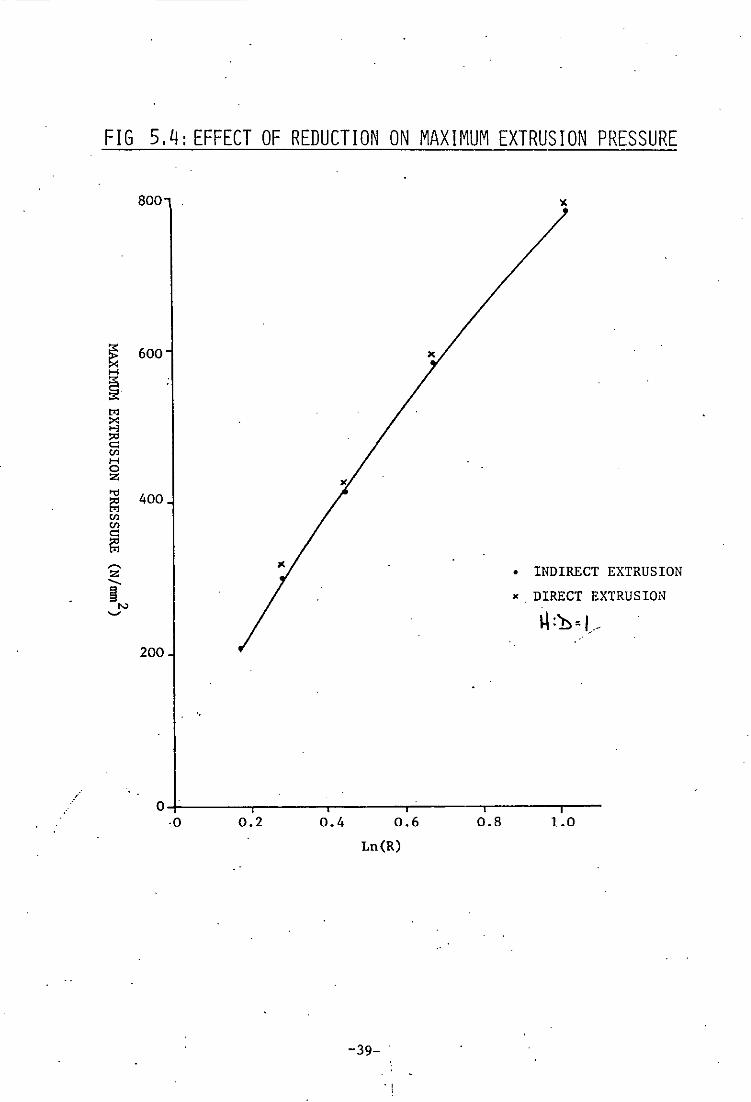
FIG 5.4: EFFECT OF REDUCTION ON MAXIMUM EXTRUSION PRESSURE
~ H
~. '" ~ ~ Ul H 0 Z
'" E:l Ul Ul c: E:l ~ z ...... II '" '-'
800
600
400
• INDIRECT EXTRUSION
" DIRECT EXTRUSION
1-\:))-1.-200
O~----~------r------r-----'i------TI----0 0.2 0.4 0.6
Ln(R)
-39- .
- . ,
0.8 1.0
.'
FIG 5.5: EFFECT OF REDUCTION ON PUNCH STRESS (INDIRECT EXTRUSION)
130 '"d
~ (") ::c en 120 >-l
t:l en en ~
Z --~ 110 "-' ~
x ..... 0
1 100 ..... 0 0.2 0.4 0.6 0.8
Ln(R)
-40-
H:))o'
...
1.0
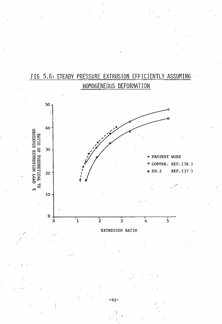
FIG 5,6: STEADY PRESSURE EXTRUSION EFFICIENTLY ASSUMING HOMOGENEOUS DEFORMATION
50
0 40 ,~ / co /
1H~ , 1"'''''
/ <iH ",' t<lO / 0
0 30 / t<lO-.j X ...,..., .. PRESENT WORK ~Eii VlO I o COPPER. REF. (36 ) t!1:l ~ z..., I .. EN.2 REF. (37 ) H 20 I t"'n I
~~ + ..., /
0 ... 10
O+------r------~----~------~----~--o 1 2 3 4 5
EXTRUSION RATIO
-41-

FIG 5.7 EFFECT OF BILLET LENGTH ON EXTRUSION PRESSURE
R = 1. 33
600
6 .. 6
"" c:: z CO ;I: ,....
HID RATIO 0 . 400 E; ~ • 0.25 ?2
0.50 ~ ><
a 0.75 200
Cl. 1.00
0 1.25
O_.~ ______________________________ -. ______________________________ ~,-__
o 25 50
PUNCH DISPLACEMZNT(MM)
-42-

FIG 5.8 : EFFECT OF BILLET LENGTH ON MAXIMUM PUNCH LOAD
R = 1. 33 600 •
•
~ •
'" ~ n ::t: t-' • ~ 500 ,-.,
?;l '-'
400+-____ .-____ -r ____ -. ______ r-____ .-__
o 0.25 0.5 0.75 1.00 1.25
BILLET H:D RATIO
FIG 5.9: EFFECT OF BILLET LENGTH ON MAXIMUM EJECTION LOAD
80 R = 1.33
60
.., ~ n H 40 H • o Z
.~ .,-., . is 20 ~
'-'
o +-----,-~---r----~------~-----,---o 0.25 0.5 0.75 1.00 1.25
BILLET H:D RATIO
-43-
600
200
" .
. FIG 5.10:DIFFERING EXTRUSION CHARACTERISTICS WITH 'DIRECTION
R = 1.33
H:D = 1
,
--------------------- ---,..., -----..... "" -------~---~--~-
INDIRECT
DIRECT
\ \
'O~--__ --------------------------~--------------------------~--~' o 25 50
PUNCH DISPLACEMENT (MM)
-44-
... c: z· .-n
'" t"' 0 > t:' ~
~ Z ~
1500
1000
500
FIG 5.11:DIFFERING EXTRUSION CHARACTERISTICS WITH DIRECTION
------
R = 2.78 H:D = 1
-- ---- - --------
- INDIRECT
--- DIRECT
\
---
O~ ________________________________ r-______________________________ ~
o 25 50
PUNCH DISPLACEMENT (MM)
-45-
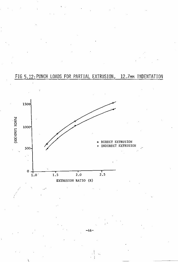
FIG 5,12:PUNCH LOADS FOR PARTIAL EXTRUSION, 12,7MM INDENTATION
150
100
o DIRECT EXTRUSION
500 • INDIRECT EXTRUSION
04---~--,-------.-------r----1.5 2.0 2.5
EXTRUSION RATIO (R)
-46-
\
600
200
FIG 513:PUNCH LOAD/DISPLACEMENT CHARACTERISTICS
FOR VARIOUS PUNCH ANGLES
'INDENTATION/EXTRUSION TRANSITION
.... -f ____ - '-0° ~_
I • • • • .... r-
..... '!' //j7 , ".
," ," / . I . :
I I
I
I
I I
/ / / /
/
~:..------------ .
- - - INDIRECT EXTRUSION R = 1.33
. PUNCH ANGLE eO
.... 0
--- 30 _.- 45.-60
:" /~. o .".
o 25 o
PUNCH DISPLACEMENT(MM)
-47-
. !

'". . ,.
FIG 514: EFFECT OF PUNCH ANGLE ON MAXIMUM EXTRUSION PRESSURE
FOR DIRECT AND INDIRECT EXTRUSIONS
R ; 1.33 680
I
~ I e
660
)( DIRECT EXTRUSION • INDIRECT EXTRUSION
560~----,-----~--~-r----~-----'-----' o 10 20 30 40 50 60
PUNCH ANGLE e (DEGREES)
-48-
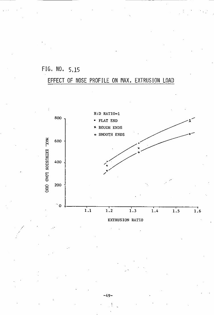
FIG. NO. 5.15
EFFECT OF NOSE PROF I LE ON r1AX. EXTRUS ION LOAD
H:D RATIO=l 800 . ./ • FLAT END "
" ROUGH ENDS
o SMOOTH ENDS 0-
~ 600
~: t'l >< H j:g
400 </ '" H 0 Z 0/ t'"' ./
~ ,.'
'"' 200 1:;] ~
" 0 1.1 1.2 1.3 1.4 1.5 1.6
EXTRUSION RATIO " ,
-49-

CHAPTER 6
METAL FLOW DURING EXTRUSION
.-"'"
6.1 GENERAL
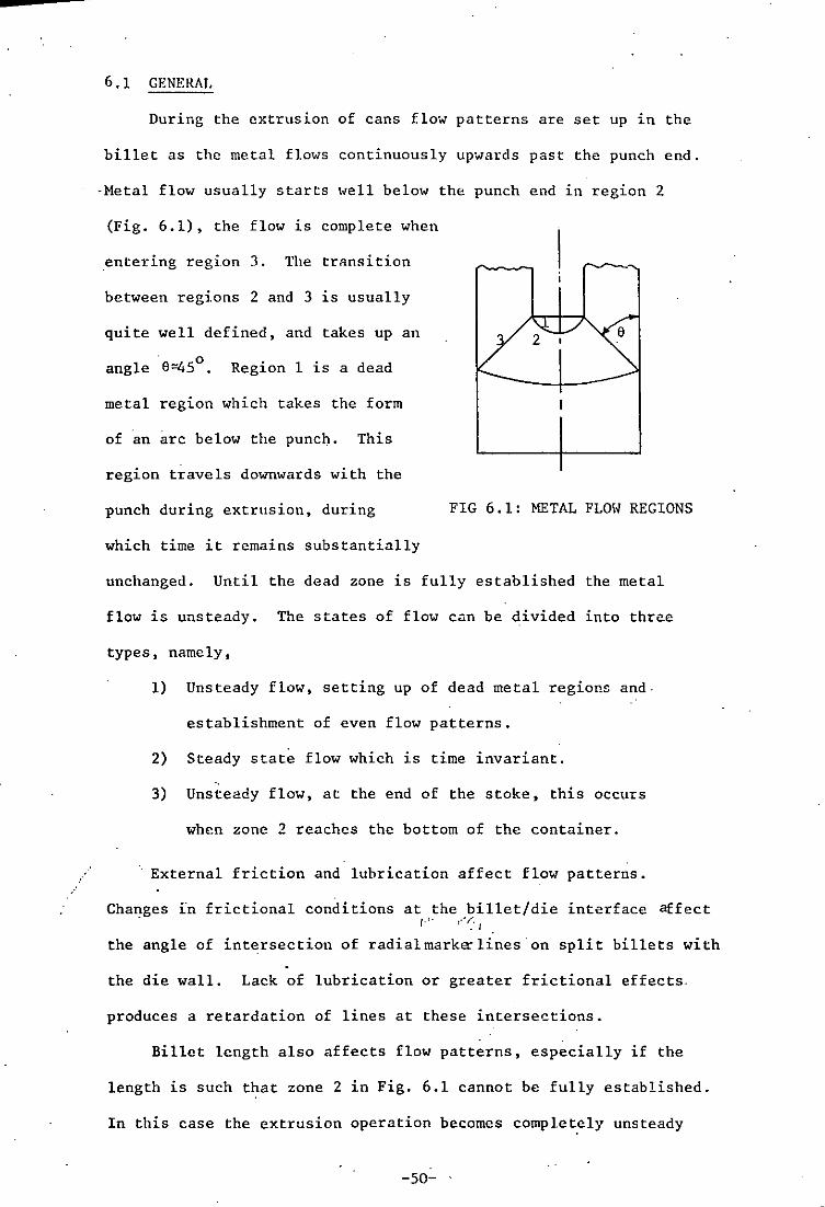
During the extrusion of cans flow patterns are set up in the
billet as the metal flOlvs continuously up'wards past the punch end.
-Metal flow usually starts well below the punch end in region 2
(Fig. 6.1), the flow is complete when
.entering region 3. The transition
between regions 2 and 3 is usually
quite well defined, and takes up an
angle' 9"450 • Region 1 is a dead
metal region which takes the form
of an arc below the punch. This
region travels downwards with the
punch during extrusion, during
which time it remains substantially
FIG 6.1: METAL FLOH REGIONS
unchanged. Until the dead zone is fully established the metal
flow is unsteady. The states of flow can be divided into three
types, namely,
1) Unsteady flow, setting up of dead metal regions and·
establishment of even flow patterns.
2) Steady state flow which is time invariant. "
3) Unsteady flow, at the end of the stoke, this occurs
when zone 2 reaches the bottom of the container.
External friction and lubrication affect flow patterns.
Changes in frictional conditions at the billet/die interface affect . r·'· t-'~I
the angle of intersection of radialmark~lines'on split billets with
the die wall. Lack of lubrication or greater frictional effects.
produces a retardation of lines at these intersections.
Billet length also affects flow patterns, especially if the
length is such that zone 2 in Fig. 6.1 cannot be fully established.
In this case the extrusion operation becomes complet,ely unsteady
-50- .

state flow,·as there is insufficient material for a steady state to
be fully established. The state of flow at the end of the stroke
. will be fully discussed in Chapter 8.
6.2 STEADY STATE FLOW
Once the dead metal regions are fully established a steady
state of flow takes place during which time vertical flow lines remai~
unchanged and a repeatable or time invariant flow pattern predominates.
Steady state flow is easily achieved in forward extrusion, but in
backward extrusion the limited height/diameter ratio of the punch
means that the steady flo" period exists for only a short time, if
at all when punches are short or billets small in height.
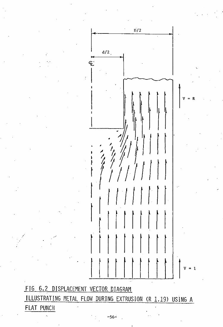
If billets are deformed in increments and the displacement of
material plotted from one stage to the next, a displacement vector
diagram can be drawn (see Fig. 6.2). This is a steady state pattern
showing the nil velocity at the dead metal region, and indicating
how metal flows from the main body of the billet to form the tube
wall; the material velocity increases from 1 at the outset to R
after deformation.
When a steady state predominates it is then possible to use the
results for visi9plasticity analysis which can be used to calculate
strain rates, strains and stress distributions throughout the billet
as has been done by Thomsen et aZ(23) for forward extrusion. Such
work :i:nvolving much computer programming is very time consuming but
yields very useful results. An analysis similar to that of Thomsen (26)
was carried out by Mehta for backward extrusion using conical ended
punches. Unfortunately the data from the flow line points is not
smoothed, and the results are subsequently ·rather inaccurate •
. The establishment of the dead metal zone takes longer at larger
extrusion ratios, hence the length of time during which steady state
-51- .

flow exists is shorter at larger extrusion ratios, particuluily as
the onset of the final stage occurs sooner also at high extrusion
ratios. In fact at very large extrusion ratios, the steady state nlaY
not exist in backward extrusion, although it almost certainly does at
low extrusion ratios.
6.3 DEAD. METAL REGIONS
As described previously, the dead· metal region in flat punch
P ,extrusion takes the form of an arc below the punch, the nimensions of
which are plotted in Fig. 7.2 of Chapter 7. The dimensions of the arc
for a particular extrusion ratio are those which will tend to minimise
the extrusion load. The dead metal region is very well defined at lo~
extrusion ratios but less so at high ratios. At R=278 the characteristic
arc is very difficult to define as shown in section 6.5.
Dead metal regions are found frequently in forming operations,
o typically in the forward extrusion of rods through dies of 180 , here
metal collects in the die corner in a similar way to backward
extrusion. A typically well formed dead metal region is shown in
Plate 6.1. More detailed photographs showing dead metal regions are
shown in the section dealing with incremental forming.
6.4 MICROSTRUCTURES
./ ·Plate 6.2 shows the macrostructures of several extruded cans.
The material is more heavity worked at the inside of the can where it
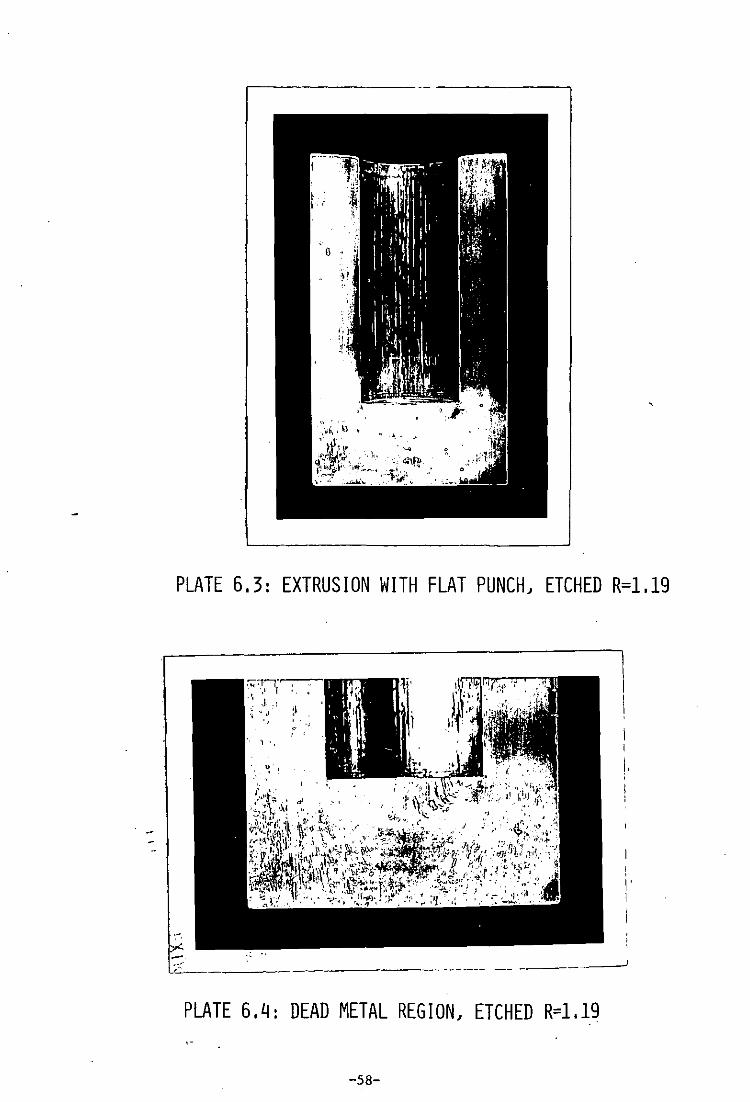
is much harder. Plates 6.3 to 6.6 show more close-up macrostructures
including close-ups ~f dead metal regions which are clearly seen.
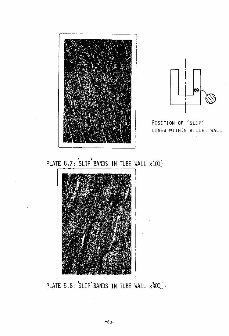
Along che sides of the extruded cans slip'bands can be found l.n
some cases, Plates 6.7 and 6.8. These bands, which· are simil.ar to (.38)
those found by Cockcroftin forward extrusion, radiate outwards from
-52-
·
/
·the.inner wall of the can at an angle of approximately 45 0 and ~re
probably formed in the transition zone which exists between the
deforming material and that which has completed deformation. There
--again a line of approximately 450
is observed r . .ldiating downwards.
from the punch corner. Such bands are undoubtedly formed during the
transition through this region.
Another interesting feature seen in Plate 6.9 is the way the
dead metal zone collapses on reaching the bottom of the die. At such
high extrusion ratios the zone is seen to split up into two circular
arcs at the bottom of the punch; such flow is not observed in
exfrusions at low extrusion ratios.
6.5 EXTRUSION DIRECTION
Extrusion direction has an effect on forming loads and on
defect formation. Differing frictional effects do however produce
slight differences in flow patterns between the two methods. In the
case of indirect extrusion, transverse marker lines meet
o the edge of the extruded product at an angle of 90 ; whereas in the
case of direct extrusion a lag is observed in the intersection of
such lines. This is due to additional friction at the interface
between the hillet and the die wall.
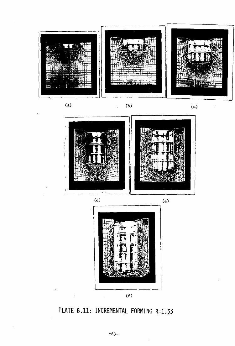
6.6 INCREMENTAL FORMING
Each extrusion ratio was examined using split marked billets
formed in increments during the extrusion process. Photographs were
taken of the billets after each forming increment and these are
shown in Plates 6.10 to 6.13.
The setting up of the dead metal regions is clearly seen and
it is.noted that the establishment of the dead metal region at 'u -larger extrusion ratios takes longer than at lower ratios. Hence
-53-

the existance of a steady state is much less likcly or short lived
at larger extrusion ratios.
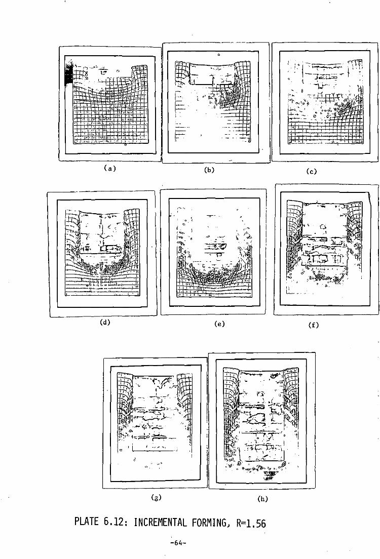
Several plates, notably 6.10G, 6.11E and 6.12G shot. clearly
the boundary between the metal flow and tube wall as being a well
defined line at approximately 450 to the cup wall.
'" The onset of cavitation can be clearly observed, particularly
in plates 6.10F, 6.10H and 6,llE and 6.1IF. Again it is clearly
observed that cavitation commences when the remaining billet thickness
becomes less ,than the wall thickness of the cup.
The metal flow region compares well with the model constructed
, .' (1) , / by Av"tzur wLth the wall flow boundary and dead metal zones comparing
almost exactly. The differences lie in the lower boundary of the
deforming zone which extends in practice much further than the zone
as predicted by Avitzur. In most cases once half of the billet has
been extruded, where H:D=I, the metal flow boundary has already reached
the bottom of the die, this again points to the fact th&t steady state
flow is very short lived Ln the backward extrusion of cups.
6.7 FLOW WITH CONICAL PUNCHES
Metal flow was observed using a variety of conical punch end
profiles. Plate 6.14 shows the state of metal flow for a variety of
punch angles. Except at very low 'angles, cavitation* is absent.
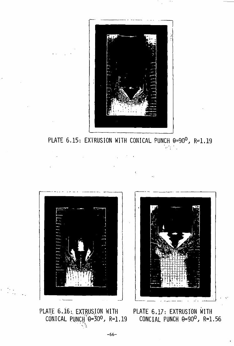
Plates 6.15 to 6.17 show how flow lines are formed when conical
ends are used. The less pointed the ends, the more likely is the
existance of a dead metal region around the profile. The deformation
zone is much smaller'than for flat punches, starting just below the
end point. It can again be seen that the inner edge of the formed
tube is much more highly worked than the outer edge.
* Cavitation is a Lifting of the corner of the biL~et which occurs towards the end of the' extrusion process, and is discuGsed fuZly in Chapter 8.
-54-
;
6.8 FLOH HITH NOSED PUNCHES
Experiments were conducted using nosed punch ends, one set
rough and one set smooth. Different loads were observed and the
state of metal flow was observed using split billets with scribed
grids on the mid plane.
Plates 6.18 and 6.19 show a comparison between the flat punch
and rough and smooth nosed punch profiles in the form of formed split
billets. As seen from these plates the rough end produces comparable
results to that of flat punch extrusion; whereas the smooth end
profile produces better flow with less evidence of built up edge.
Build up in front of the nosed profile exists in both the rough end
extrusion and the flat punch extrusion. The depth of deformation
zone is much less with the smooth end than the rough, where it
compares with flat punch extrusion.
-55-
. D/2
d/2,
r [rttt,1 / ........ 11 11111fl
.... 11 Itttll l v "
FIG 6,2 DISPLACEMENT VECTOR DIAGRAM ILLUSTRATING METAL FLOW DURING EXTRUSION eR 1,19) USING A FLAT PUNCH' .
. -56-

,----- ---~ -- - ~----, ,
PLATE 6.1: EXTRUSION ~IITH FLAT PUNCH R=1.33 ", !' '.
.. , \ .' '.
PLATE 6.2: SELECTION OF SECTIONED CUPS
-57-
,
PLATE 6.3: EXTRUSION WITH FLAT PUNCH, ETCHED R=1.19
----- ------
PLATE 6.4: DEAD METAL REGION, ETCHED R=1.19
-58-
!,
! I' I
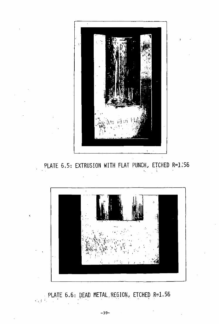
PLATE 6.5: EXTRUSION WITH FLAT PUNCH, ETCHED R=1:56
PLATE 6.6: DEAD METAL, REGION, ETCHED R=1.56 .: •• .' . ..' , I .. ;. ~ '.
-59-
~---------- -
POSITioN OF 'SLIP' LINES WITHIN BILLET WALL
• • PLATE 6.7: SLIP BANDS IN TUBE WALL xiOO~
, , - -,
PLATE 6.8: SLIP BANDS IN TUBE WALL x400~J
-60-

PLATE 6.9: COLLAPSE OF DEAD METAL REGIONS
I
. I
PLATE 6.14: SPLIT SECTIONS WITH CONCIAL PUNCHES, ETCHED R=1.19
-61-

. (a). (b) . (c)
, .
(d) (e) (f)
(g) (h)
PLATE 6.10: INCREMENTAL FORMING~ R=1.19
-62-
(a) (b)
(d)
(f)
I I
(e)
PLATE 6.11: INCREMENTAL FORMING R=1.33
-63-
(c)
o
~ .. i
F
(a) (b) (c)
(d) (e) (f)
(g) (h)
PLATE 6.12: INCREMENTAL FORMING) R=1.S6
-64-

(a) (b)
".
(c) (d)
(e)
PLATE 6.13: INCREMENTAL FORllING R=1.96
-65-
-------
f
PLATE 6.15: EXTRUSION WITH CONICAL PUNCH 8=90°, R=I.19
"
,'-
, , , " '
, , '
PLATE 6 • .16:, EXTRUSJ ON vllTH PLATE 6.17: EXTRUS rON WITH CONICAL PUNCH':9=300, R=1.19 CONCIAL PUNCH 9=90°, R=l. 56 .. .,--.
-', ~!
-66-

PLATE 6.18: COMPARISON BETWEEN BILLETS FORMED WITH FLAT AND NOSED RAMS) R=1.56
. I
PLATE 6.19: COMPARISON BETWEEN BILLETS FORMED WITH FLAT , .
AND NOSED RAMS) R=1.33
-67-
CHAPTER 7
UPPER BOUND SOLUTIONS TO BACKWARD EXTRUSION
.--'
...

7.1 THE UPPER BOUND TECHNIQUE
The bounding technique, or limit analysis, is a useful theory
for the estimation of forming loads. Upper bound" predict the upper
limit of such loads, and lower bounds the lower limits. As lower
bounds are difficult to define accurately one usually concentrates
on· the upper bound technique. As the load in practice cannot exceed
the upper bound load, the problem reduces to that of finding the
lowest, and therefore most accurate, upper bound solution.
The upper bound predicts the maximum power required for
deformation. The total power is the sum of the individual power
required to overCOllie shear and friction losses plus the power of
internal deformation. Fundamental to the upper bound technique is
the division of the body into zones, for each of which a velocity
field (mathematical description of the flow of the material) is
derived. The velocity field is then used to define a strain rate
field. The better the zones, or nearer to describing the actual
deformation taking place, the more the power required reduces, and
thus brings the solution closer to the .actual value.
In order for a solution to be kinematically admissible, three
conditions must be satisfied, namely:-
1. Incompressibility equations must be satisfied.
2. Continuity across the velocity discontinuity must be
satisfied.
3. Velocity boundary conditions must be satisfied.
A number of sli~ line field solutions exists for plain strain
extrusion, but a model described by Avitzur (1,30) for axially
symmetric backward extrusion was thought to.describe very well the
conditions prevailing during extrusion in practice.
-68-
.'
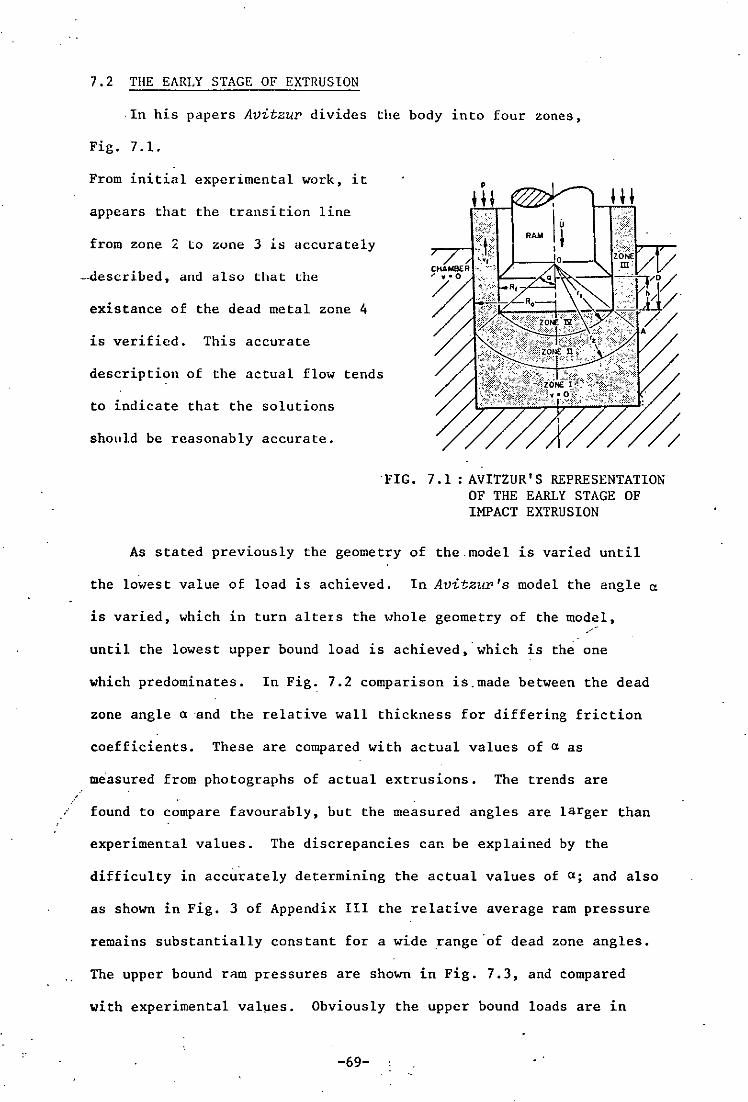
7.2 THE EARLY STAGE OF EXTRUSION
·In his papers Avitzul' divides the body into four zones,
Fig. 7.1.
From initial experimental work, it • appears that the transi tion line
+H
from zone 2 lo zune 3 is accurately "'--r-l~J~ 1L--.".Ca.I~~-~ -.described, and also that the
existance of the dead metal zone 4
is verified. This accurate
description of the actual flow tends
to indicate that the solutions
should be reasonably accurate.
·FIG. 7.1: AVITZUR' S REPRESENTATION OF THE EARLY STAGE OF IMPACT EXTRUSION
As stated previously the geometry of the.model is varied until
the lowest value of load is achieved. In Avitzur's model the angle n
is varied, which in turn altets the whole geometry of the model,
until the lowest upper bound load is achieved,·which is the one
which predominates. In Fig. 7.2 comparison is. made between the dead
zone angle (l ·and the relative wall thickness for differing friction
coefficients. These are compared with actual values of n as
measured from photographs of actual extrusions. The trends are
found to compare favourably, but the measured angles are larger than
experimental values. The discrepancies can be explained by the
difficulty in accurately determining the actual values of n; and also
as shown in Fig. 3 of Appendix III the relative average ram pressure
remains substantially constant for a wide range ·of dead zone angles.
The upper bound ram pressures are shown in Fig. 7.3, and compared
with experimental values. Obviously the upper bound loads are in
-69-

excess of the experimental values.
7.3 USE OF A NOSED RAM FOR EXTRUSION
Where a dead metal zone exists, the metal must shear over itself
in order to flow; since shear losses are proportional to 00/13
whereas friction losses are proportional to moo/13, where m is a
friction factor and varies between 0 and 1, it would be desirable to
eliminate the dead zone by replacing the flat ram with an appropriate.ly
nosed ram. The geometry of the nose is again optimised in a similar
way to the original model. Fig. 7.4 illustrates the difference
between upper bound loads for both flat and nosed rams.
7.4 EXTRUSION AT TIlE END OF TIlE STROKE
At the end of the stroke; the original model breaks down; so
Avitzur has constructed a new model which applies to the end of the
extrusion stoke, Fig. 7.5.
Here, the body is split into 2
zones,one below the punch and the
other flowing up by the punch
sides. One of the most
important aspects of such models
is the prediction of defects •.
The major defects encountered in
extrusion, namely cavitation and
internal cracking ·or fishskin
are examined.
Fig. 7.5 2 ZONE REPRESENTATION OF SOUND FLOH DURING THE FINAL STAGE OF IMPACT EXTRUSION
An expression is derived which examines the minimum external
pressure required to prevent cavitation. If this expression is re-
arranged and minimized, an .expression can be derived for the
-70-

/
minimum slug thickness to prevent cavitation. This is plotted Ln
Fig. 7.6.
In practice it has been observed that cavitation most often
occurs when the slug thickness becomes less than the wall thickness
of the extrudate, see Fig. 7.7, i.e. cavitation will occur when
T < Ro - Rf or
If this criterionis taken, and TIRo is plotted against RolRf as in
Fig. 7.5, by plotting TIRo against 1 - 1 (Ro/Rf)' the results lie
within those of Avitzur's model, which is found to predict reasonably
well the onset of cavitation.
All the calculations and computer programs involved in the
calculation of the upper bound solutions are to be found in
Appendix Ill.
Fig. 7.7
f
Ro
CRITICAL SLUG THIC~,ESS FOR PREVENTION OF CAVITATION
-71-
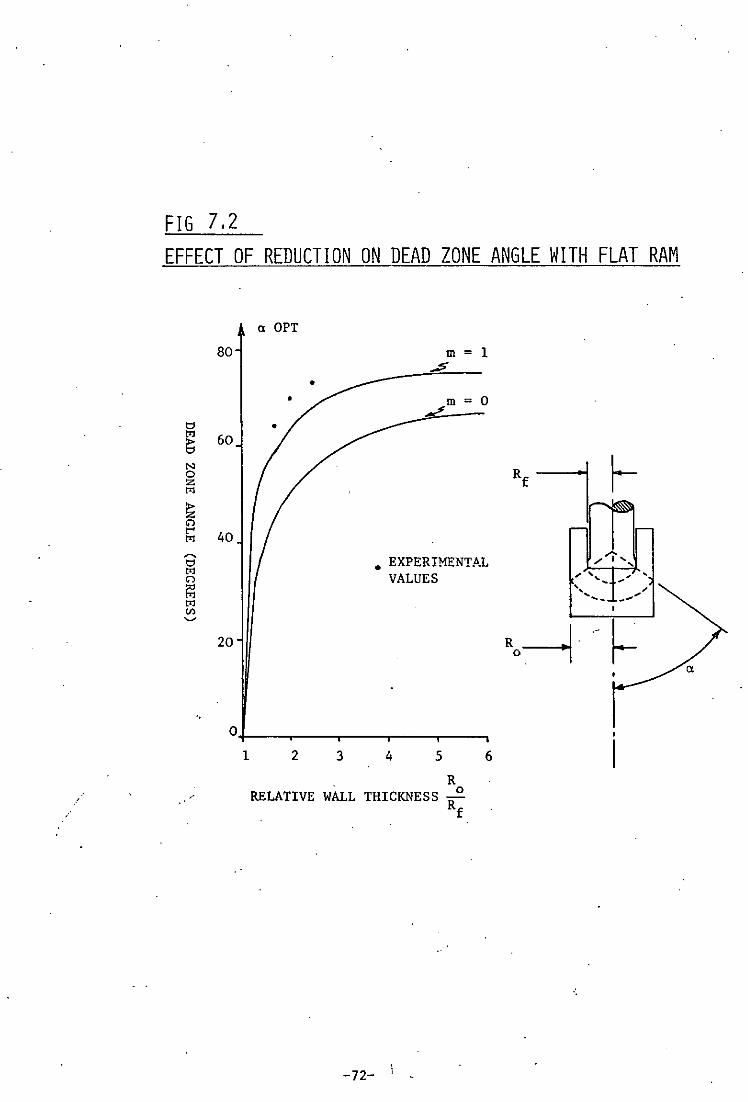
FIG 7,2 EFFECT OF REDUCTION ON DEAD ZONE ANGLE WITH FLAT RAM
t:l to:!
E; N 0 z to:!
~ '"' ..... to:!
~
t:l to:!
'"' ~ to:! Cl)
'"
"
a OPT
80 m = 1 ~
• m = 0 L
60
40
• EXPERIMENTAL VALUES
20
O+---~--'----r---. __ -' 1 2 3 4 5
. R RELATIVE WALL THICKNESS R
0
f
-72-
6
R'I r-.............. ,
" " , -~ , --, , .-'- -' ,
Ro---1
_.
~

FIG NO 7.3
UPPER BOUND RAM PRESSURES FOR EXTRUSION
WITH FLAT R/\M
P . -= 0 00 '
~ = 0.1, PR = Average ram pressure Rf
PR 00 7
6
5
4
3 \
\ \.
2 "-
INERTIA EFFECTS NEGLECTED
m=l--~//
'--
/'_0-. --- m=O
• EXPERIMENTAL VALUES
1~--~---r---~---~---' 1 2 3 4 5 6 Ro
Rf
RELATIVE WALL THICKNESS
-73-
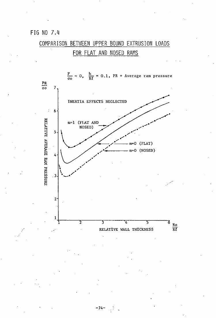
FIG NO 7,4
COMPARISON BETWEEN UPPER BOUND EXTRUSION LOADS FOR FLAT AND NOSED RA~1S
P - ~ 0 00 '
h Rf ~ 0.1, PR ~ Average ram pressure
PR 00 7
INERTIA EFFECTS NEGLECTED
6
m~l
5
4
~ ./ '" \ / [:l \ ,/ C/l ,3 -_./ en c::: [:l
2
/' /' -
,,' .". .
". ,,' ,,-
," _,/--m~O (FLAT) /
/'_4---m~0 (NOSED) /'
/'
1+-__ ~ _______ ~ ___ ~ __ ~ 4
RELATIVE WALL THICKNESS
-74-
Ro Rf

FIG 7,6 UPPER BOUND SOLUTION FOR MINIMUM SLUG THICKNESS
TO PREVENT CAVITATION VERSUS REDUCTION AND FRICTION T Ra 0.23
0.20
0.16
Cl> t"' c:: '" H ::c H n ~ to1 Cl> Cl> ...... n 0.12 >< t"' H § to1 ~
~ H c:: Cl>
0.08
0.04
1.0
p - = 0 cro
INERTIA EFFECTS NEGLECTED
T = Base thickness
1.1
RELATIVE WALL THICKNESS
-75-
Ra-Rf>T THEORY
1.2 Ra Rf

CHAPTER 8
EXTRUSION DEFECTS
. '.
I
·8.1 GENERAL
Extrusion defects in backward extrusion arise due to a variety
of reasons including friction, l11hr.l.C'.ation ~nd the nature of metal
flow. Differing defects arise at various stages of the process and
at different extrusion ratios.
Three.main defects arising during extrusion are a) cavitation,
or a lifting of the lower edge of the cup b) the formation of a
dead metal ring around the bottom edge of the cup which separates
from the body of the cup, and c) fishskin or internal tearing of the
GQ product at stages along the inside of the cup wall. Fig. 8.1
illustrates these defects.
8.2 CAVITATION
Cavitation is a common extrusion defect and is found to occur
at the end of the process when the base thickness becomes less than
the wall thickness. This has been proved in Chapter 7 theoretically
by upper bound techniques, and has been observed in practice. This
means that for a given base thickness, cavitation occurs more readily
at lower extrusion ratios.
Examples of cavitation are shown in Plates 8.1 and 8.2. Here
the lifting of the side walls is clearly apparent, especially in
Fig. 8.2. This is a very short specimen where contact with the side
walls is short and therefore the restriction in terms of friction ...
which oppose cavitation is minimal.
The effect of friction between the formed cup and the die wall
acts as a restraining force to prevent cavitation, and it is found
that at higher extrusion ratios where these forces are large, and
where friction is high due to a long length of emerging product·in contact
\with the die cavitation or its onset is prevented or delayed.
-76- .
Fig. 7.6 illustrates the base thickness criterion for the onset of
cavitation.
Cavitation in backward extrusion can be compared with piping
in forward extrusion which also occurs at the e'nd of the extrusion
process.
8.3 INTERNAL CRACKING
Circumferential cracks occur on the inner wall surface of pierced
cups. Theoretically, cavitation occurs before cracking, but this is
not so in practice.
Cracking is governed by the magnitude of the local hydrostatic
pressure, the ductility of the material at the point in question and
by the stress field around the point.
The defect is illustrated in Plates 8.3, 8.4 and 8.5 and is
found to occur only at high extrusion ratios. Cracking was found to
occur only during direct extrusion and not during indirect extrusion.
Also it occurs during incremental forming by indirect extrusion, this
is due to the lack of pressure by the friction between the formed cup
wall and the die wall.
The presence of an imposed pressure on the wall of the emerging
product would reduce and probably eliminate both cavitation and
cracking.
/ Cracking also occurs in the form of circumferential cracks in
forward extruded rods.
Cracking in the backward extrusion of aluminium has been
'. '(39) 1 b Go' (40) • reported before by D~pper and a so y oyu and others 1n the
cold piercing of magnesium.
-77-.
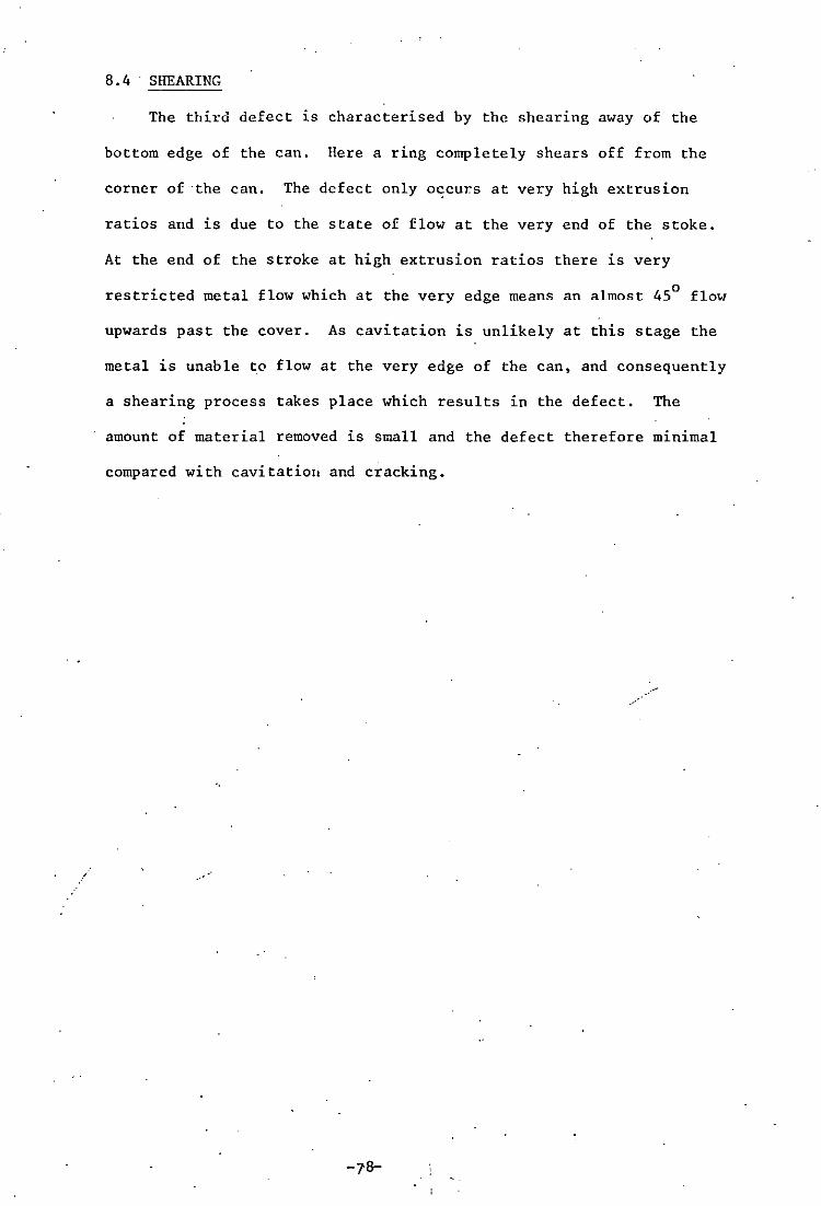
8. 4 SHEARING
The third defect is characterised by the shearing away of the
bottom edge of the can. Here a ring completely shears off from the
corner of ·the can. The defect only o~curs at very high extrusion
ratios and is due to the state of flow at the very end of the stoke.
At the end of the stroke at high extrusion ratios there is very
restricted metal flow which at the very edge means an almost 450 flow
upwards past the cover. As cavitation is unlikely at this stage the
metal is unable to flow at the very edge of the can, and consequently
a shearing process takes place which results in the defect. The
amount of material removed is small and the defect therefore minimal
compared with cavitatioll and cracking.
.-

FIG (8,D SKETCHES SHOHING EXTRUSION DEFECT FORMATIorJS
n
A) CAVITATION
SHEAR __ """'\
LINE ~ . ,
B) DEAD METAL RING .-.--
~~
/ \ i I
c) INTERNAL CRACKING OR FISHSKIN
-79- .
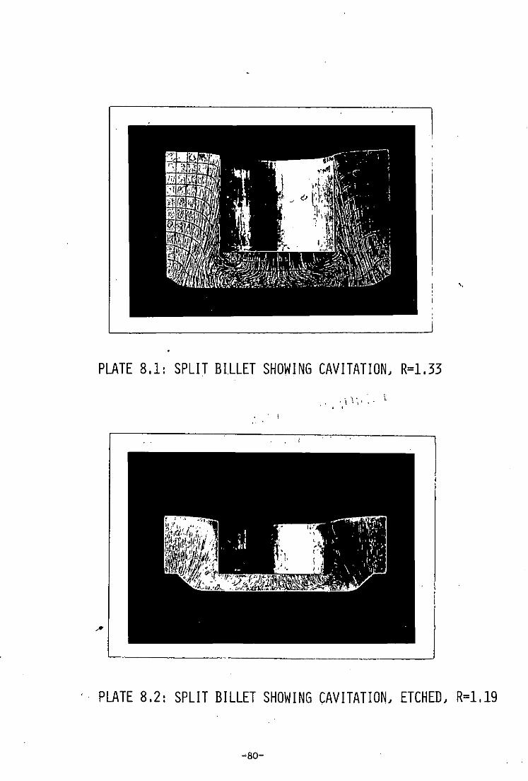
PLATE 8.1: SPLIT BILLET SHOWING CAVITATION, R=1.33
. I
'. PLATE 8.2: SPLIT BILLET SHOWING CAVITATION, ETCHED, R=1.19
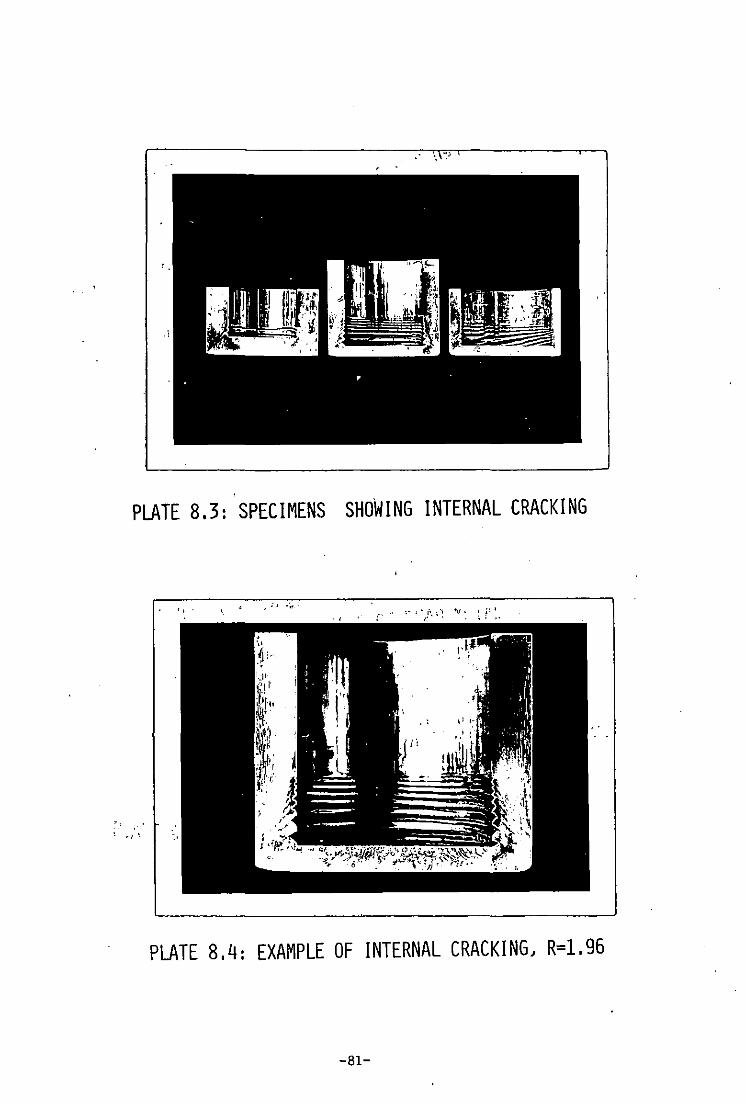
. .,-~ . "
PLATE 8.3: SPECIMENS SHOWING INTERNAL CRACKING
PLATE 8.4: EXAMPLE OF INTERNAL CRACKING, R=1.96
-81-

PLATE 8.5: EXAMPLE OF INTERNAL CRACKING, R=2.78
-82-

· .
CHAPTER 9
CONCLUSIONS
..

The followin:; conclusions can be drawn from the discussions of
previous chapters:-
9.1 FORMING LOADS
a) The load/extrusion ratio relationships obtained for backward
extrusion agreed well with published data.
b) ·Extrusion load increases both with extrusion ratio and billet
length.
c) The extrusion load for direct extrusion is greater by up to 10%
than that for indirect extrusion.
d) ·Optimum angles exist for extrusion with conical punches.
e) Extrusion loads are decreased by using noscd punch ends with
rough profiles similar in geometry to dead metal regions; and·
are reduced by up to 10% further by the use of smooth nosed punch
ends.
9.2 METAL FLOW
a) Dead metal regions exist for all extrusion ratios, using flat
punches, with increasing angle of zones for increasing extrusion
ratios. These compare well with theoretically defined fields
derived from an upper bound model.
b) The depth of deformation region is such that the existance of a
steady state is very short lived.
c) The process can be roughly divided into three types of flow,
i) Initial setting up of dead metal regions, ii) Steady state
flow, iii) Flow ~t the end of the stroke.
d) Deformation is much heavier at the inside wall of the formed cup.
e) The dividing zone between the deforming region and the cup wall
forms a boundary line of approximately 450 to the die wall.
£) Inc·remental forming has revealed details of flow during the
-83-
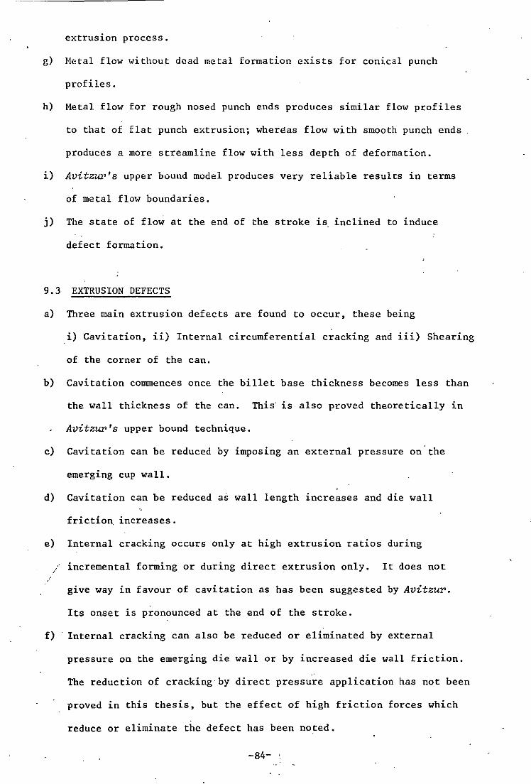
extrusion process.
g) Hetal flow without dead metal formation exists for conical punch
profiles.
h) Hetal flow for rough nosed punch ends produces similar flow profiles
to that of flat punch extrusion; wher~as flow with smooth punch ends
produces a more streamline flow with less depth of deformation.
i) AvitzUl"s upper bound model produces very reliable results in terms
of metal flow boundaries.
j) The state of flow at the end of the stroke is inclined to induce
defect formation.
9.3 EXTRUSION DEFECTS
a) Three main extrusion defects are found to occur, these being
i) Cavitation, ii) Internal circumferential cracking and iii) Shearing
of the corner of the can.
b) Cavitation COmmences once the billet base thickness becomes less than
the wall thickness of the can. This' is also proved theoretically in
Avitzur's upper bound technique.
c) Cavitation can be reduced by imposing an external pressure on'the
emerging cup wall.
d) Cavitation can be reduced as wall length increases and die wall
friction increases.
e) Internal cracking occurs only at high extrusion ratios during
incremental forming or during direct extrusion only. It does not
give way in favour of cavitation as has been suggested by Avitzur.
Its onset is pronounced at the end of the stroke.
£) Internal cracking can also be reduced or eliminated by external
pressure on the emerging die wall or by increased die wall friction.
The reduction of cracking'by direct pressure application has not been
proved in this thesis, but the effect of high friction forces which
reduce or eliminate the defect has been noted.
-84- .
g) Shearing of the very corner of the extruded can occurs at the very
end of the stroke at high extrusion ratios due to restriction of
metal flow. Its appearance'is absent in the presence of
cavitation.
9.4 PRACTICAL IMPLICATIONS OF THE WOP-K
From a practical point of view, the thesis illustrates the
origins of defect formation and their cures; also how metal flow
influences grain &tructure and therefore product properties
throughout the component.
More wide reaching practical implications lie in a furthering
of the fundamental understanding of metal flow during backward
extrusion. Taken further, the work could be combined with
visiop~~icity analysis in order to yield large amounts of data
on stress formation throughout the billet.
-85-
-~ ,
CHAPTER 10
RECor,lMENDATIONS FOR FURTHER WORK

Several recommendations for useful further work can be made in
the light of conclusions drawn from this work. These are briefly as
follows :-
a) Further studies of incremental forming using more exact measuring
techniques could be carried out to define exactly when the onset
of steady state flow occurs, and how long it prevails, i.e. to
establish the transition point between the three metal flow states.
b) Having established where steady flow occurs, it would then be
'possible to construct a full visioplasticity analysis to the
process, in a similar way to that of Thomsen et a~ in their
examination of forward extrusion through conical dies. The
analysis would be relatively easy for concial punch profiles,
but none too difficult for flat punch extrusion as it has been
shown that the deformation boundaries, especially dead metal
zones, are clearly defin3d. Such a detailed analysis would be
a useful contribution to metal flowmecbanks and would yield
much interesting data on metal flow and forming loads.
c) Defect formation can be prevented by the application of pressure
to the emerging can wall. The magnitude of pressure required to
prevent such defects arising could be measured and would be
.valuable practical information. As the difference in friction
between direct and indirect extrusion is sufficient to prevent
internal cracking, the magnitude of pressure required to prevent
this defect will undoubtedly be small.
d) Further work could be carried out to examine the effect after ejection of
residual s tresses- and expansion of the extruded cans. This would
-86-

also provide useful data on the effect of friction by interference
on defect formation.
e) Further work could be done using a modified version of Avitzur's
model in which deformation zone boundaries are modified to agree
more fully with those found in practice in. the hope of establishing
more accurate results .
. ~87~

ACKNOWLEDGEMENTS
The author wishes to thank the Science Research Council for
providing the award which enabled this work to be carried out,
and also Professor R.J. Sury, Director of Research, for the use
of departmental facilities. My sincere thanks are extended to I
Dr. G.F. Modlen, Project Supervisor, for his continual advice,
support and encouragement throughout the work.
Acknowledgements are also due to Mr. W.R. Abrey for technical
assistance, and Mr. R. Withers for assistance with photography.
Finally, grateful thanks are extended to my fiance,
Miss J.M. Briers, for her unfailing support and encouragement
·throughout the entire project, and for her proficient typing
of this thesis.
.-.-"
-88-

1. AVITZUR, n. ct.al. 'Impact Extrusion - upper bound analysis of the
early otage'. J .• of Eng. for lndus try, Nov. 1972.
2. EVERHART, P.E. 'Impact and cold extrusion of metals'
pp. 74-75. Chemical Publishing Co.Inc. New York 1964.
3. LEVY, B.S. 'Guidelines for selecting a cold extruding steel'
Metals Engineering Quarterly, May 1973.
4. KENNICOTT, I?L. 'Carbide tools for cold extrusion'
Metals Engineering Quarterly, May 1973.
5. 'Notes on the heat treatment of cold extrusion punches'
P.E.R.A. Report No. 113, May 1963.
6. 'Typical failures of bacJa,;ard extrusion punches'
P.E.R.A. Report No. 205, November, 1969.
7. MORGAN, R.A.P. 'Tooling for cold extrusion'
Sheet Metal Industries, February 1961, pp.lOO-120.
8. 'Cold extrusion of carbon steels - Effects of tool geometry on
b~c~rd extrusion' P.E.R.A. Report No. 102.
9. EVERHART, P. E . 'Impact and co ld extrusion of me ta ls '
pp.48-5l. Chemical Publishing Co. Inc. New York, 1964.
10. PUGH, H.Ll.D et al. 'Design considerations arising from cold
extrusion research' N.E.L. Report No.24 March 1962.
11. VAIDYANATHAN P. V. et al. 'A theoretical method of efficient
extrusion die design' J. of the" Institute of Metals, Vol. 101,
1973, pp.79-84.
12. SHABAIK, A.H. 'An approach to die design in extrusions'
Trans. A.S.M.E. Nay 1971.
-89-
13. SCIIEY,. J .A, (Metal· Defol'm(d~O>I 1?Y'I)ccsses - friction and lubrication'
l1at:lcce1 Dcbber Inc, New York 1970,
14. ·HATKINS, H.T. 'Cold forming and Gxtrusion of steel'
The Institute of Heta1s Review (Part 1) pp.123-146, 1973.
15. ASHCROFT, K. & LAI.JSON, G. S. 'The effect of ram speed on the
extrusion of lead and aluminium' N.E.L. Report No.2. June 1961.
16. CRUDEN, A.K. 'The Cold Extrusion of Steel Tubes and Cans'
N.E.L. Report No. 472 November 1970.
17. KASHAR, L.J. et al. 'Deformation criteria for predicting the cold
extrusion pressures of metals' in Heta1 Forming, Ed. by
HOFFMANNER A.L. pp.131-161, Plenum Press, New York 1971.
18. PEARSON, C.E. & PARKINS, R.H. 'The extrusion of metals'
Chapman & Hall Ltd. 1960.
19. LAMBERT, E.R. & KOBAYASHI, S. 'A theory on the mechanics of
axisymmetric extrusion through conical dies' J.Hech.Eng;Sci.
Vol. 10. No.5. 1968.
20. LAMBERT, E.R. & KOBAYASHI, S. 'An'approximate 'solution for the
mechanics ofaxisymmetric extrusion'. Advances in Hachine
Tool Design and Research pp.253-269 1968.
21. SHABAIK A.H. 'Compute2'-aided Visioplasticity solution to
axisymmetric extrusion through curved boundaries'
22.
J. of Eng. for Industry November 1972.
SHABAIK, A.H. & KOBAYASHI, S. 'Computer Application to the
visioplasticity method' J. of Eng. for Industry Hay 1967.
23. SOHRABPOUR, S. & SHABAIK, A.H. 'Local friction coefficients in
axisymmetric extrusions Of alwm'nium' J. of Eng. for
Industry Hay 1970.
24. HEDRANO, R. E. & GILLIS P. P. 'Visioplasticit;y techniques in
axisymmetric extrusion' J. of Strain Analysis Vo1.7 No.3 1972.
-90-

---------
25. FAR,AG, M.N. & SELLARS, C.M. '/lnalysis of double max~mwn flow
pqtte:rns in qxisymmel;y·ic exl;rusion of H30 alWlr(-nium aUo!!'
J. of Ma,terials Technology, May 1975.
26. HEHTA, n.s. 'Mechanics of tube extrusion and Piercing'
N.Sc. thesis. Univ. of Californi.a, Berkley, June 1968.
27. KUDO H. & JOHNSON W. 'The mechanics of metal extrusion'
Manchester Univ. Press 1962.
28. KOBAYASHI, S. 'Upper bound solutions ofaxisymmetric fO:r7Tling .
problems (1) Trans. A.S.M.E. May 1964.
29. 'KOBAYASHI, S. 'Upper bound solutions ofaxisymmetric forming
problems (11) Trans. A.S.M.E. November 1964.
30. AVITZUR, B. et. al. 'Impact extrusion - upper bound analysis of
the end of the stroke' J. of Eng. for Industry, Aug. 1973.
31. AVITZUR, B. 'Metal Forming - Processes & Analysis'
McGraw-Hill, 1968.
32. THOMSEN,E.G., et.al. 'Mechanics of Plastic Defo:r7Tlation in Metal
Processing' Macmillan Co. New,York 1965.
33. JOHNSON, \~. et.al. 'Plane Strain Slip Line Fields'
Edwqrd Arnold 1970.
34. HOWARD, F. 'Designing with impact extruded components'
Eng. Materials & Design, October 1956.
35. VON ZEERlEDER, A. & VON BERG, E. 'Relationship of the force
requirements in the extrusion of tubes of pure aluminium
and various. aluminium alloys. SCHWEIZER ARCHIV, 3:109, 1937.
36. MODLEN, G.F. 'A simple sub-press for reverse cold extrusion of
metals' Sheet Metal Industries, November 1966.
37. MCKENZIE, J., N.E.L. Report No. 117, October, 1963.
-91-
3S. COCKCROFT M.G. 1\ MACLEAN, M.S. 'Mechanical Proper' ties of CoZ.d
Extruded Products' 4th International Meeting on Cold
Forging, Dusse1dorf, lS.l0.70.
39. DIPPER, M., DAS FLIESSPRESSEN VON RUELSEN IN RECHNUNC UND VERSUCR,
Arch. f. Eisenhuettives, 20, 276. 1949.
40. COBYU, I. et.al. 'Studies on Impact Extrusion'
J •. Japanlnst. Met., 18, 1954, 19, 1955 & 20, 1956.
41. RYDER, C.R. 'Strength of Materials'.
42. PUCR, R.Ll.D. & DONALDSON, C.J. 'Hydrostatic extrusion -
A ·Review' N.E.L. Report No.6l0, March 1976.
-92-

ApPENDIX I
DIE STRESS CALCULATIONS
... "
·/

( ') R ' 'I D' COt th _ 1. equ1.,'eu. 'l-e ., Y'eng-
Experimental materials of pure aluminium or soft aluminium
alloys were originally proposed for the present work; but in
order to enhance the scope of the apparatus, the die was
designed to withstand forming pressures to be expected in the
extrusion of hard aluminium alloys, with a mean yield strength
in the order of 460 N/mm?.
E~uation (1) has been found to yield reasonably accurate
predictions of forming loads for lead and aluminium, under
axially-symmetrical _conditions
where:-
p = 0.8 + 1.5 In R y
P = extrusion pressure
................
Y = mean yield strength = 460 N/mm2
R = extrusion ratio
Maximum load occurs at the maximum extrusion ratio of 2.78.
Hence, froin (1)
The extrusion die must therefore withstand an internal
2 pressure of 1072 N/mm •
(ii) Die Stress Calculations
(1)
Die Materials:- Inner die ring Hardened die steel, yield strength 2009 N/mm
2
Outer die ring Hardened EN25, yield strength 1236 N/mm2
-1-
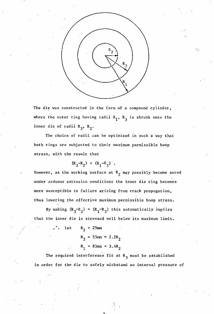
I
The die was constructed in the form of a compound cylinder,.
where the outer ring having radii RI' R3 is shrunk onto the
inner die of radii R3, R2
•
The choice of radii ~an be optimised 1n·such a way that
both rings are subjected to their maximum permissible hoop
stress, with the result that
However, as the working surface at R2 may possibly become sored
-under arduous extrusivn conditions the inner die ring becomes
more susceptible to failure arising from crack propogation,
thus lowering the effective maximum permissible hoop stress.
that the inner die is stressed well below its maximum limit.
.. . let
R3 = 55mm = 2.2R2
RI = 85mm = 3.4R2
The required interference fit at R3 must be established
in order for the die to safely withstand an internal pressure of

2 . (41) 1072 N/mm , as outlined by Ryder ,
The following analysis treats' the die as a compound
thick cylinder with open ends.
Lam~s thick cylinder equations are:
Radial stress or = b/ r 2 - a
Hoop stress ae = b 2 /r + a
where a and b are constants, and r is the radius at which
the stresses are to be found.
STRESS DUE TO INTERNAL PRESSURE:
Letting 08,r,i = 08,r at R. ~
Or = 1072 ~ 2
or1
= 0
b
R2 2
b
R2 1
- a
- a =
b
R2 2
b 2 2
3.4 R2
b
- a
2 Hence b = 1174R2 ; and by substitution a = 101.5
(2)
(3)
Hoop stresses due to internal pressure can now be calcu1ated:-
1174R; 0 82 = R2 + 101.5 = 1275.5 N/mm2
2
1174R; 2 + 101.5 =
4.84R2
1174R; . 2 + 101.5 =
l1.56R2
-3-
344 N/nnn2
2 203 N/mm

STRESS DUE TO SHRINK FIT:
The yield strength of the outer ring 1S approximately
1236 N/mm2 after heat treatment. For safety reasons and to
allow for slight variation due to heat treatment, let it be
subjected to a maximum hoop stress of ~ x yield strength
2 oeMAX
= 927 N/mm for the outer ring.
Let a suffix 0 denote stresses in the outer ring, and i those
in the inner ring.
Consider the outer ring RI' R3:
(oe 3)0 due to shrink fit = (oeMAX)O -ae 3 due to internal pressure.
now
and
(ae 3)0 =
(Oe 3)0 =
(Or 1)0 =
(oe3
)0 +
927 - 344
b 583 =
b
R2 3
= 583 N/mm2
b + a = --"'--;;:- + a Z 4.84R2
b 0 = R2
- a = - a 11.56R~ 1
(Or 1)0 583 b = = + 2
4.84R2
b 2
11.56R2
hence b = 1992R~; and by substitution a = 172.4.
/ ..•.
The unkno~i· hoop and radial stresses in the outer ring can now
be calculated:-1992R~
(Oe 1)0 + 172.4 344.8 N/mm 2 = = Z 11.56R2
(or3
)0 1992R~
- 172.4 2 = = 239.4 N/mm . . 2 4 •. 84R2
Now (ar3
)0 = (or3)i so the stresses imposed upon the inner ring
due to the shrink fit can now be calculated.
-4-
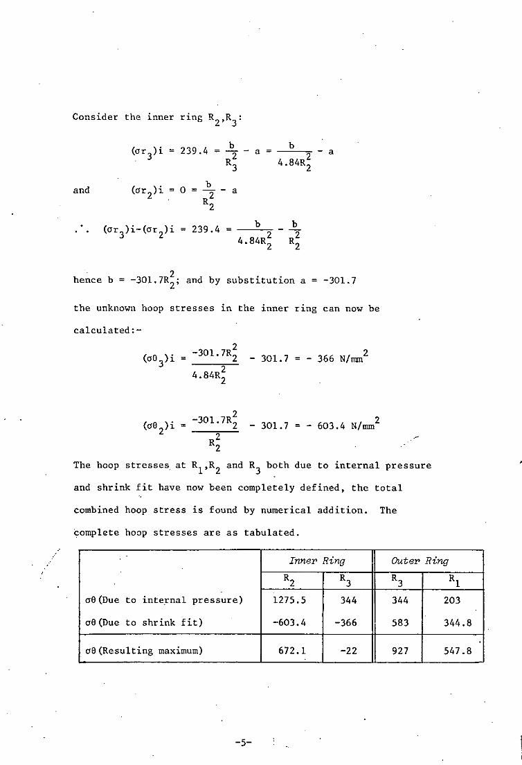
Consider the inner ring R2,R3:
(or 3) i 239.4 b b = = R2 - a = - a 2
3 4.84R
2
and (or 2)i .= 0 b = R2 - a
2
(or3)i-(or
2)i 239.4 b b
= = - R2 2 4.84R
2 2
2 hence b = -30l.7R2
; and by substitution a = -301.7
the unknown hoop stresses in the inner ring can now be
calculated:-
2 = -301. 7R2
2 4.84R2
- 301. 7 2 = - 366 N/nun
2 -30l.7R2 _ 301.7 = - 603.4 N/mm2
R2 2
.-
The hoop stresses at Rl
,R2
and R3 both due to internal pressure
and shrink fit have now been completely defined, the total
combined hoop stress is found by numerical addition. The
complete hoop stresses are as tabulated.
Inner Ring Outer Ring
R2 R3 R3 Rl
08 (Due to internal pressure) 1275.5 344 344 203
08 (Due to shrink fit) -603.4 -366 583 344.8
08 (Resulting maximum) 672.1 -22 927 547.8
-5-
.

Total absolute hoop stress due to shrink fit = 366 + 583 = 949 N/mm2
Let E for steel = 216.3 x 10³ N/mm2
Initial difference in diameter at common surface =
i (total absolute hoop stress) = diameter
949 = x 110 = 0.4826 mm 3 2l6.3xlO
The required interference fit is 0.4826 mm
As the 1nner die is to be fitted into the outer by a
temperature differential, the required temperature difference
between the rings must be calculated such that they will fit
with ease.
Temperature differential to accommodate 0.4826 mm =
Hoop strain Coefficient of expansion for steel
the coefficient of linear expansion for steel is approximately
= 0.00001116 mm/mm/oC
949 Temperature differential = --~~~~3 2l6.3xlO
"
x
" ./
1 =
0.00001116
The ~empering temperature of EN25 to attain a yield strength
of 1236 N/mm is 4500 C, which indicates that the interference fit
can be attained by fitting the outer ring on to the inner one
immediately after its withdrawal from the tempering furnace.. To
ease the operation, ,the inner die may be previously immersed in
liquid nitrogen so as to increase the clearance at the common
surface during fitting.
-6-

(UiJ Criterion [or failW'e
Although a cylinder fa'ils due to hoop stress rather than
radial stress, the shear stresses play a critical role in
determining ,the load at which failure occurs: the Huber-von~Mises
yield criterion is therefore applied.
Since yielding, if it occurs, will be under plane strain
conditions, this criterion reduces to the condition that the
difference between the principal stresses in the plane of strain
(oe-or) should equal 2Y
13 at yielding; this is equivalent to a
maximum shear stress criterion, (since max shear stress TMAX=(ae-a~/2)
Y the critical shear stress being
Consider the inner ring:
Y CRITICAL T = - =
MAXr3 2009
13 = 1160 N/mm2 for no yielding
now TMAX = !(a6MAX
+P) where P = internal pressure.
2 ," 2 From previous calculations ae
MAX = 672 N/mm ; P = 1072 N/mm
T = !(672+l072) = 872 N/mm2 MAX
The criterion is satisfied as T~!AX <
Consider the outer ring:
Y
13
P now becomes the effective internal pressure at R3 both due to
the internal pressure and the shrink fit.
-7-
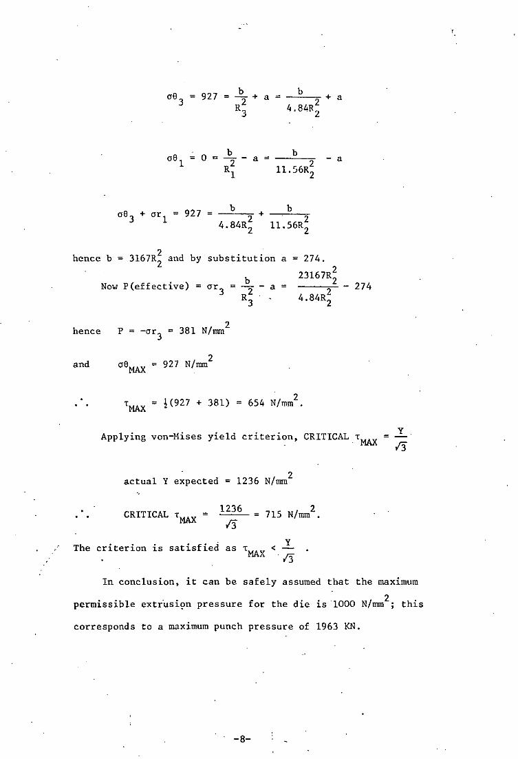
= 927 b = - +
2 R.,
J
b a=-=-~+a
4.84R~
b a = --=--'"
11. 56R~ - a
b b oe 3 + or 1 = 927 = -~-"'2 + -~-=--2'"
4.84R2 11.56R2
2 hence b = 3167R2
and by substitution a = 274.
23167R;
2 4.84R2
hence
Now P(effective) = or3
2 P = -or3
= 381 N/mm
and oeMAX
= 927 N/mm2
TMAX = !(927 + 381)
b = R2 -
3
a =
- 2 = 654 N/mm •
- 274
y Applying von-Mises yield criterion, CRITICALT
MAX =
2 actual Y expected = 1236 N/mm
CRITICAL T = MAX
1236
/3 2
= 715 N/mm •
The criterion is satisfied as T < Y MAX -/3
In conclusion, it can be safely assumed that the maximum
permissible extr'usi9n pressure for the die is -1000 N/mm2 ; this
corresponds to a maximum punch pressure of 1963 KN.
-8-
. ./
ApPENDIX 11
EXTRUSION AND COMPRESSION TOOL
DESIGN DETAILS AND HEAT TREATMENT
EXTRUSION TOOL DETAIL DRAWINGS
THIRD ANGLE PROJECTION USED THROUGHOUT
ALL DIMENSIONS IN MM UNLESS OTHERWISE STATED
TOLERANCES AS SPECIFIED (NOMINAL ±O,SMM)
'i/ MACHINE
fI GRIND
~ POLISH TO 0,1 )J/MM
-1-

... _ ..... _... ... .
See page no. 2 for parts list
•
FIG 1 SECTIONAL DIAGRAM OF THE EXTRUSION TOOL
1 ·SoaZe: Approx. J fuZZ size.
-2-
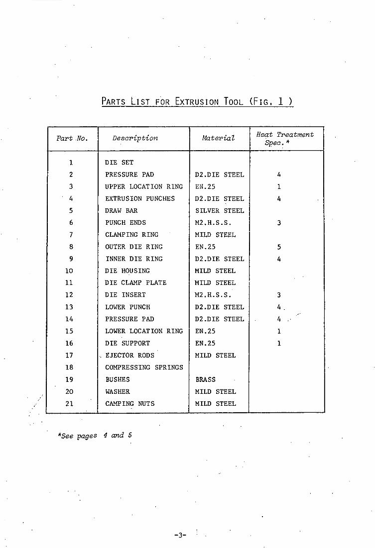
PARTS LIST FOR EXTRUSION TOOL (FIG. 1 )
Part .No. Description Material
1 DIE SET
2
3
4
5
6
7
8
9
10
11
12
13
14
15
16
17
PRESSURE PAD D2.DIE STEEL
UPPER LOCATION RING EN.25
EXTRUSION PUNCHES D2.DIE STEEL
DRAWBAR
PUNCH ENDS
CLAMPING RING
OUTER DIE RING
INNER DIE RING
DIE HOUSING
DIE CLAMP PLATE
DIE INSERT
LOWER PUNCH
PRESSURE PAD
SILVER STEEL
M2.H.S.S.
MILD STEEL
EN.25
D2.DIE STEEL
MILD STEEL
MILD STEEL
M2.H.S.S.
D2.DIE STEEL
D2.DIE STEEL
LOWER LOCATION RING EN.25
DIE SUPPORT EN.25
'. EJECTOR RODS MILD STEEL
18 COMPRESSING SPRINGS
19
20
21
BUSHES
WASHER
CA!1PING NUTS
*See pages 4 and 5
-3-
BRASS
MILD STEEL
MILD STEEL
Heat Treatment Spec. *
4
1
4
3
5
4
3
4.
4
1
1

HEAT TREATMENT SPECIFICATIONS FOR EXTRUSION AND COMPRESSION
TOOL MATERIALS
Specification 1 Material : EN25
Preheat to 600°C, raise to 830°C., soak for I hour, light
° 0 temper at 100 -150 C
Specification 2
Hardness 52 Roc.C.
Material : EN8
Raise to 850°C, soak for 1 hour, oil quench, temper
Hardness 39 Roc.C.
Specification 3 Material: H.S.S.(M2)
° ° Preheat to 800 C, raise quickly to 1210 C x 3-4 minutes soak,
quench into salts at 560°C and allo" to equalise, temper
twice by 1 hour at 620°C
Hardness 62-63 Roc.C •.
Specification 4 Material : Die Steel(D2)
Preheat to 800°C, raise qui.ckly to 10200 C x 45 minutes soak,
. ° martemper by quenching into salts at 200-220 C and allow to
equalise, temper twice by 1 hour at 200°C
Hardness: 61 Roc.C.
/
-4-

M3tcrial : EN25
Preheat to 600oC, raise to 830
oC, soak for 1 hour,
oil quench, temper to 450 0 C
Hardness 44 Roc.C.
-5-
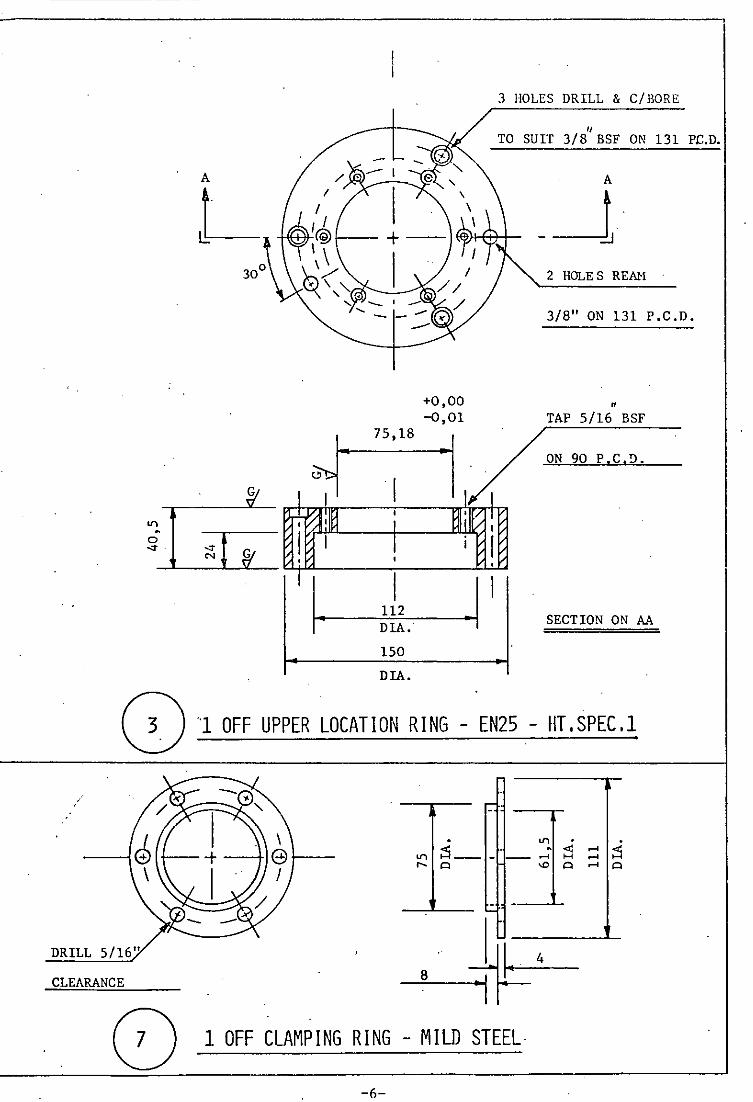
3 HOLES DRILL & C/BORE
1/ TO SUIT 3/8 BSF ON 131 PC.D.
A
L 2 HOLE S REMI
3/8" ON 131 P.C.D.
o ·1 OFF UPPER LOCATION RING - EN25 - HT.SPEC.l
DRILL 5/16"
CLEARANCE
~ 1 OFF CLAMPING RING - MILD STEEL
-6-
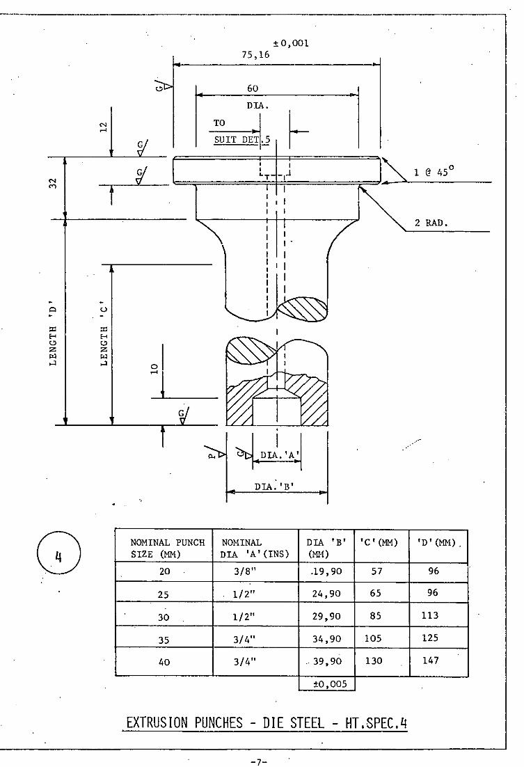
N
'"
Q . pO H <!> z
'" o-l
G
TO
± 0,001 75,16
60
DIA.
SUIT DET.5
~.~~=========t~T~,~-:~J========~~~.~A __ ~1 __ @_4_5_0 ____ __
U . pO H <!> z
'" o-l 01 ~l
NOMINAL PUNCH SIZE (MM)
20
25
30
35
40
I
I I .
I I I
I I
.
~ DIA. 'B'
NOMINAL DIA 'A' (INS)
3/8"
1/2"
1/2"
3/4"
3/4"
DIA I B' 'C'(MM) (MI1)
.19,90 57
24,90 65
29,90 85
34,90 105
. 39,90 130
±0,005
EXTRUSION PUNCHES - DIE STEEL - HT.SPEC.4
-7-
2 RAD.
'D' (MM).
96
96
113
125
147

HEX. HEADS
TO SUIT
WELD & TURN
OFF FLUSH
5 OFF DRAVI BARS - SILVER STEEL ..
TO FIT PUNCH OF • A' (MM) • B' DIA. NOMINAL SIZE (MM)
20 124 1/4 B.S.F.
25 124 1/4 B.S.F.
30· 130 5/16 B.S.F.
35 132 3/8 B.S.F.
40 165 3/8 B.S.F.
-8-
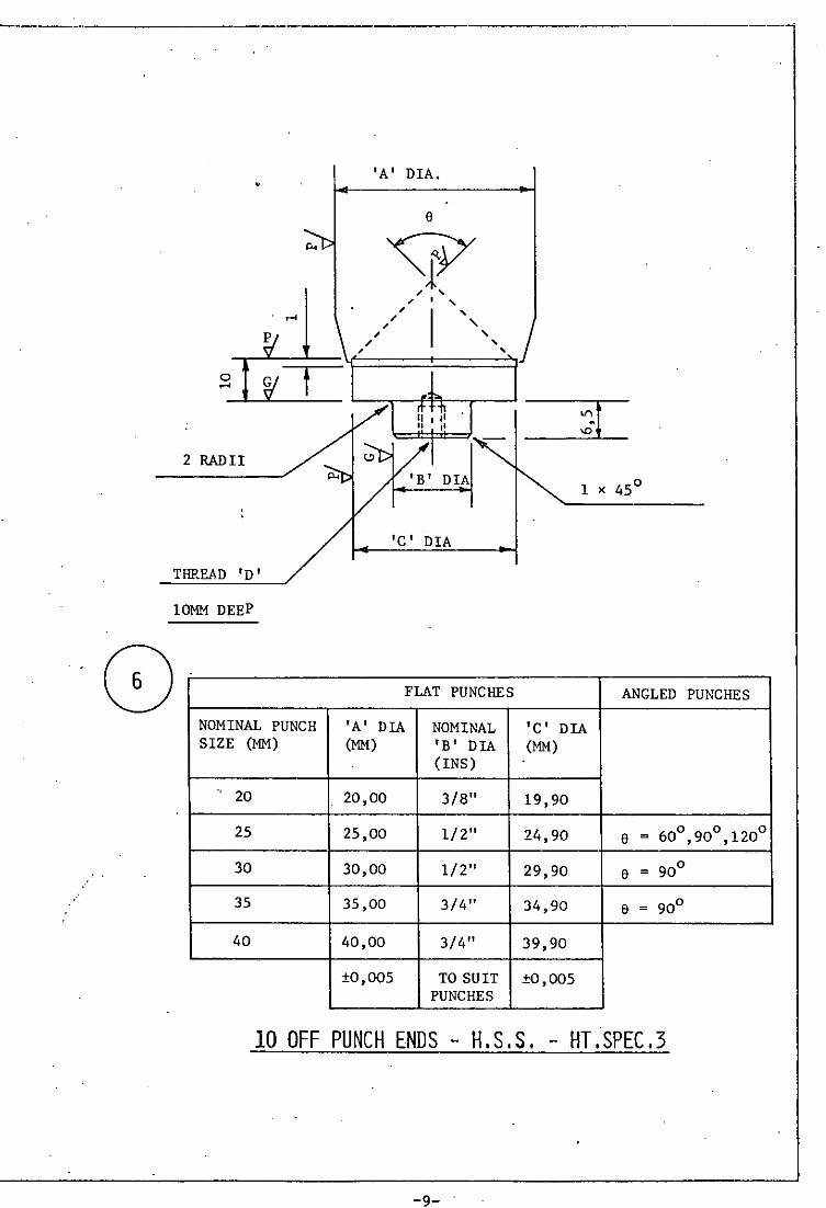
----------,
o ....
2 RADII
•
THREAD 'D'
10MM DEEP
G f
NOMINAL PUNCH SIZE (MM)
" 20
25
30
35
40
'A' DIA .
e
'c' DIA
FLAT PUNCHES ANGLED PUNCHES
'A' DIA NOMINAL 'c' DIA (MM) 'B' DIA (MM)
(INS)
20,00 3/8" 19,90
25,00 1/2" 24,90 e = 600 900 1200 , ,
30,00 1/2" 29,90 e = 900
35,00 3/4" 34,90 e = 900
40,00 3/4" 39,90
±0,005 TO SUIT ±0,005 PUNCHES
10 OFF PUNCH ENDS - H,S.S. - HT.SPEC.3
-9-
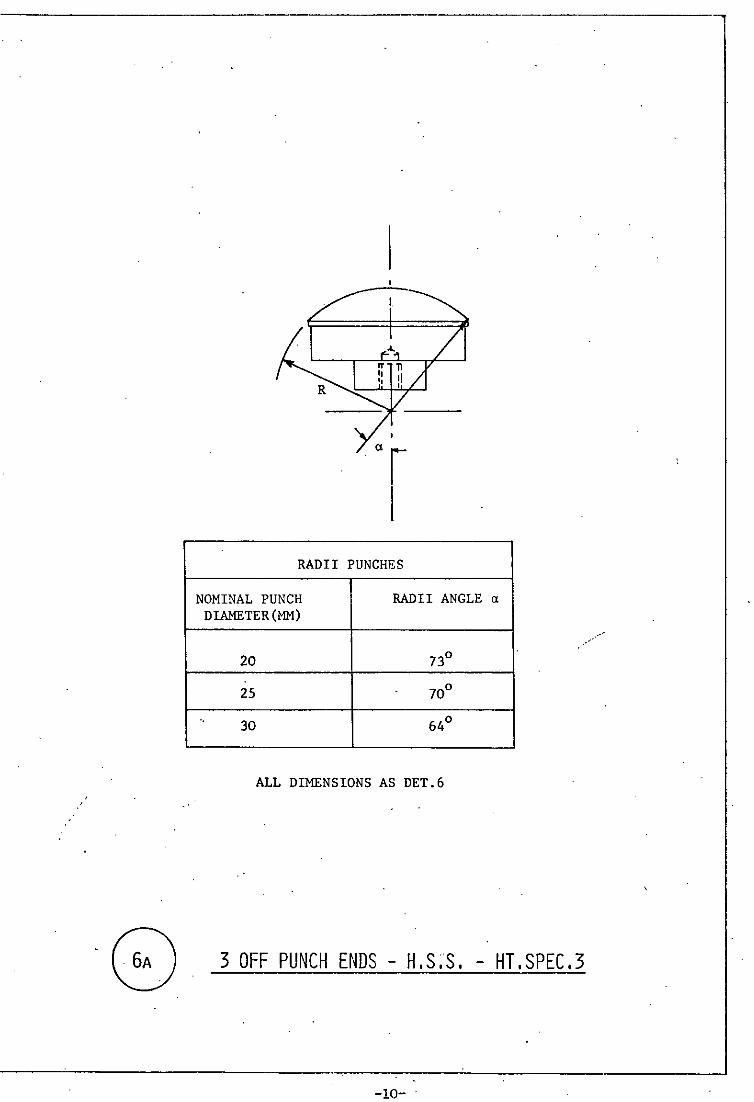
RADII PUNCHES
NOMINAL PUNCH RADII ANGLE Cl
DIAMETER(MM)
20 73°
2S 70°
"" 30 64°
ALL DIMENSIONS AS DET.6
3 OFF PUNCH ENDS - H.S;S. - HT.SPEC.3
-10- "
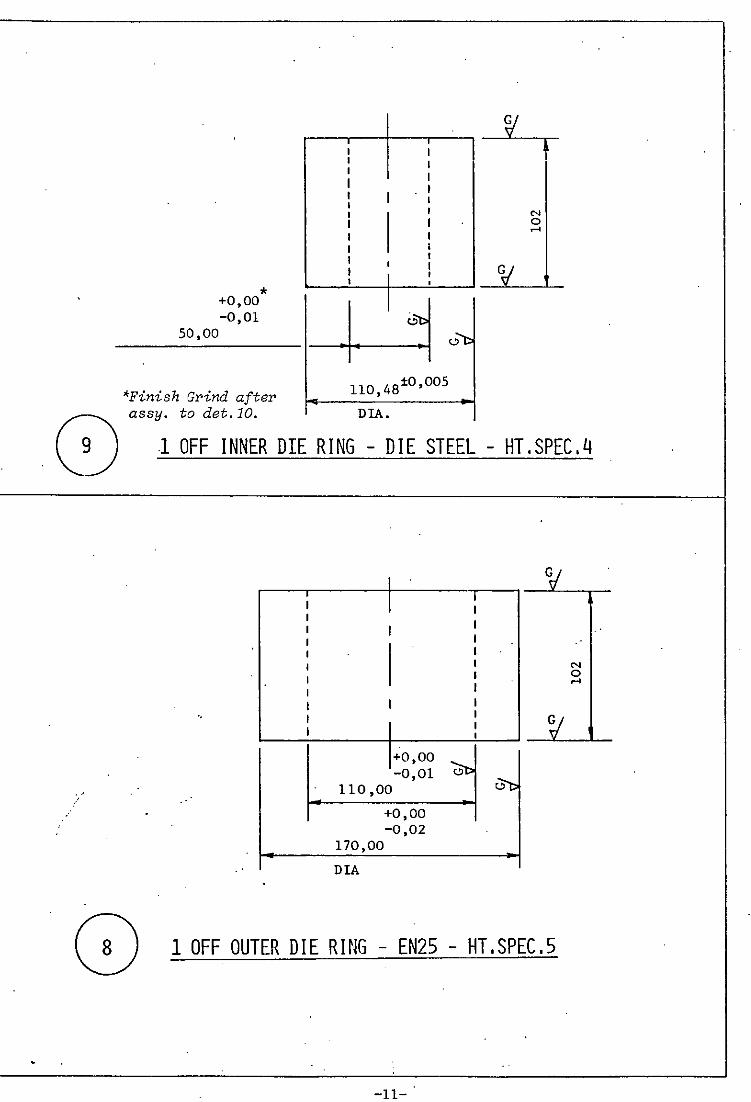
... ..
* +0,00 -0,01
50,00
'Finish Grind after assy. to det.10.
; ; I I I I I t I I I I
I I
I I I I I I I
I I I I t I I
I ,
I c.,'t>
110 4810 ,005 , DIA.
,-,"b
N o .-<
1 OFF INNER DIE RING - DIE STEEL - HT,SPEC,4
I CV t I I
I I I I I
I t I I I I N
I I 0
I .-<
I t I I
'. I I
~ I I I
+0,00 0l> -0,01
~ 110,00
+0,00 -0,02
170,00
DIA .
1 OFF OUTER DIE RING - EN25 - HT,SPEC,5
-ll- .
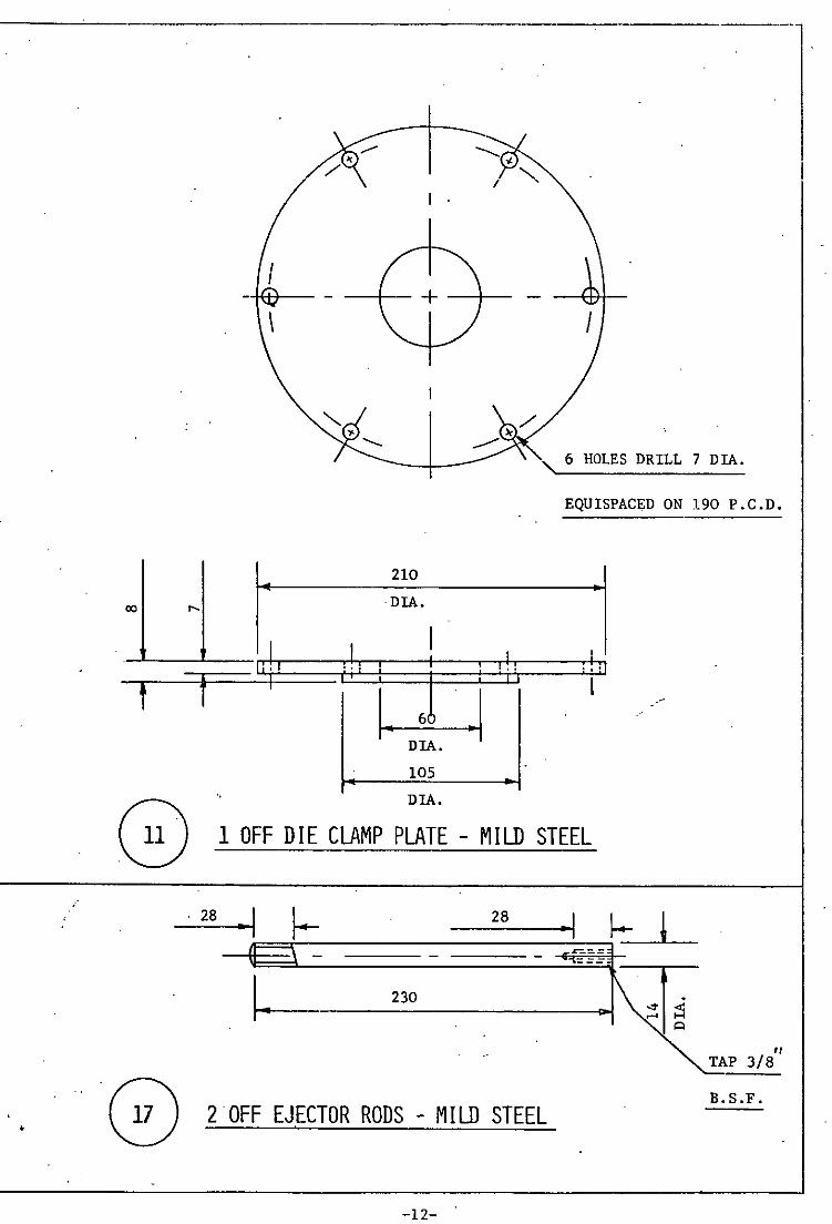
•
00 "
; f
(0 . 28
I I
\
11 i I I !! :
1 •
210
DIA.
I i 1 i
~ 105
DIA.
I
" 6 HOLES DRILL 7 DIA.
EQUISPACED ON 190 P.C.D.
, !! ! I ! ' !I I I
1 OFF DIE CLAMP PLATE - MILD STEEL
28
z-:.- =
TAP 3/8 '/
o 2 ·OFF EJECTOR RODS - MIlJJ STEEL B.S.F .
-12-
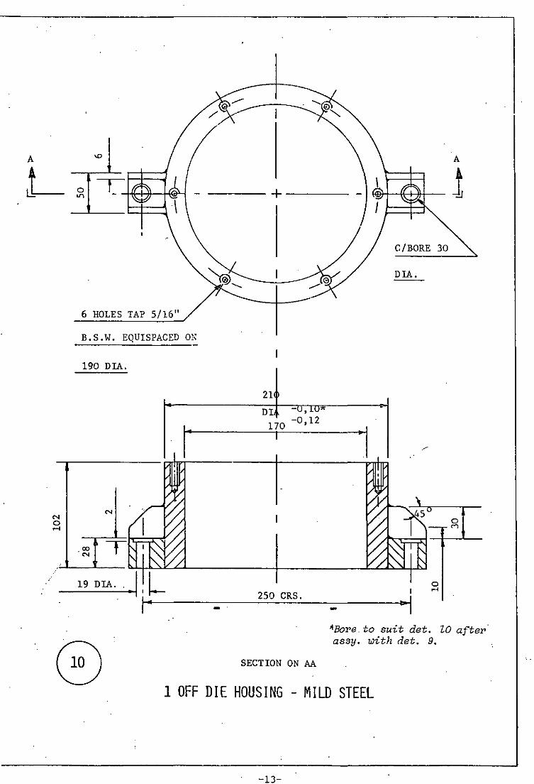
A
L~
'" o .....
6 HOLES TAP 5/16"
B.S.W. EQUISPACED ON
190 DIA
19 DIA .. • 1, l •
A
----+----
21
DI -U,lU"
170 -0,12
250 CRS .
SECTION ON AA
"I
C/BORE 30
DIA.
o .....
*Bore.to suit det. za after· assy. with det. 9.
1 OFF DIE HOUSING - MILD STEEL
-13-
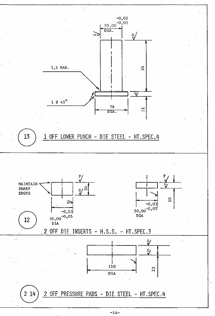
--------- ---
-0,02 -0 03
~~ DlA. G/ '-' 1 I 1
1,5 RAD. I ..,. I N
~ , I 1
)1 W
1 @ 45° T
. 1 I· 76 N DtA. .-<
o 1 Off LOWER PUNCH - 0 I E STEEL - HT. SPEC. q
MAINTAIN ~m ~o SHARP I G (0")
EDGES
~ .. -o,j 50,00-0,05
DIA
I I I
~ 50 00-0,05 ,
DIA
.2 OFF DIE INSERTS - H,S,S, - HT.SPEC.3
: . I I
I. •
~. I 110 .
DIA
~ 2 Off PRESSURE PADS - DIE STEEL - HT.SPEC.q
-14~
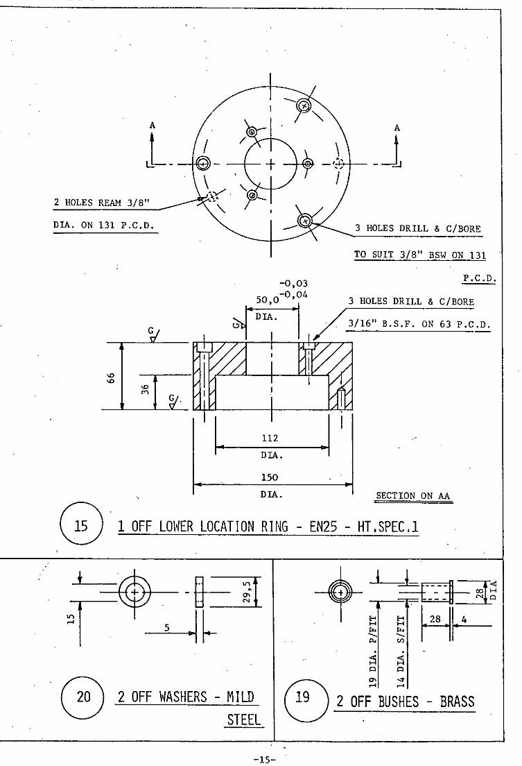
2 HOLES REAM 3/8"
DIA. ON 131 P.C.D.
"" C"l
3 HOLES DRILL & C/BORE
TO SUIT 3/8" BSW ON 131
-0,03 P.C.D.
, ~4 3 HOLES DRILL & C/BORE
~1 D~. I /3/16" 8.S.F. ON 63 P.C.D.
--~~-~~~----+-----~~
112
DIA.
150
" DIA. SECTION ON AA o . 1 OFF LOWER LOCATION RING - EN25 - HT.SPEC.l
* -{ETI -~< ~~C:-H~ r ~~ §'H~ , H r.<o --p.,
;S ;S Q Q
0) '" ...,.
.-< .-< ~ 2 OFF WASHERS - MILD 2 OFF BUSHES - BRASS STEEL
-15-

22!
A· rt ~ 'L. ~
·1 ~ , I
" . 1 I 1 ., . ~tJ I , , '4-J
i-~ 1 '-, I Y: . I I I
V I 56
2 HOLES DRILL DIA •
• . & TAP 3 /8 B.S.F. & C/BORE 150 DIA.
~ 1 OFF DIE SUPPORT - EN25 - HT,SPEC,l
12,5RAD. , ! ! ' .. ~- 13:£ ~ ~ RADIUS .. ~ ~ ~
. 92 ~
2 OFF SUPPORT HANDLES -ALUf1 r N rUM
-16-
! Eo-< ::> u
~ N
o G '"
o co
t

COMPRESSION TOOL DETAIL DRAWINGS
THIRD ANGLE PROJECTION USED THROUGHOUT
ALL DUIENSIONS IN MM UNLESS OTHERWISE STATED
TOLERANCES AS SPECIFIED (NOMINAL ±O,SMM)
..; MACHINE
W GRIND
r; POLISH TO 0,1 IJ/MM
-17-
....
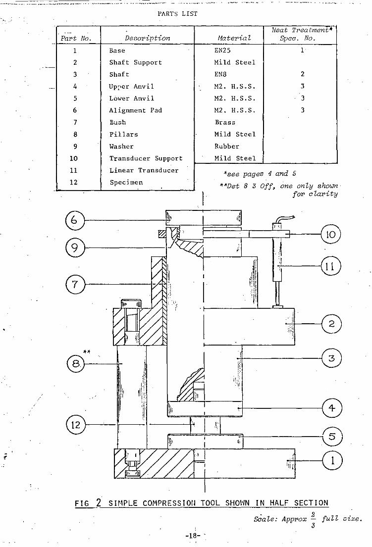
~ ••• ,~~" •• _ .,_ ••. ' .~ .......... 'M ........... ~ ___ •• '" .. " •.• _._ ••• ". ~ •••••• _._. _____ .,_ .- ,., ....... - ... .
PARTS LIST
>
- -- 1ieat Trea t;ment~ Part No. Description Material Spec. No.
1 Base EN25 1
2 Shaft Support Mild Steel
3 Shaft ENS 2
- 4 Upper Anvil M2. H.S.S. 3
5 Lower Anvil M2. H.S.S. 3
6 Alignment Pad H2 • H.S.S. 3
7 Bush Brass
8 Pillars Mild Steel
9 Washer Rubber
10 Transducer Support Mild Steel
11 Linear Transducer 'see pages 4 and 5 12 Specimen **Det 8 ;3 Off, one only shoum
- for c lar1- ty
~I' ,
;i~
® I' l 'I
r , @
;1 il'
"
0 l'lt
'I:: - !
i :1 2
• :~ :;,\l
** j: "
,11 : :! I!} " : ~!!
I. li . ~
Ii'!! ;, ,. ,
:1 \' ',Ii
~ r' ", , I' r., 5
:,W
~ ,
"i" , .
FIG 2 SH-1PLE COMPRESSIOfl TOOL SHOI'/N IN HALF SECTION ---2 Scale: Approx full oize. ;3
-18- -
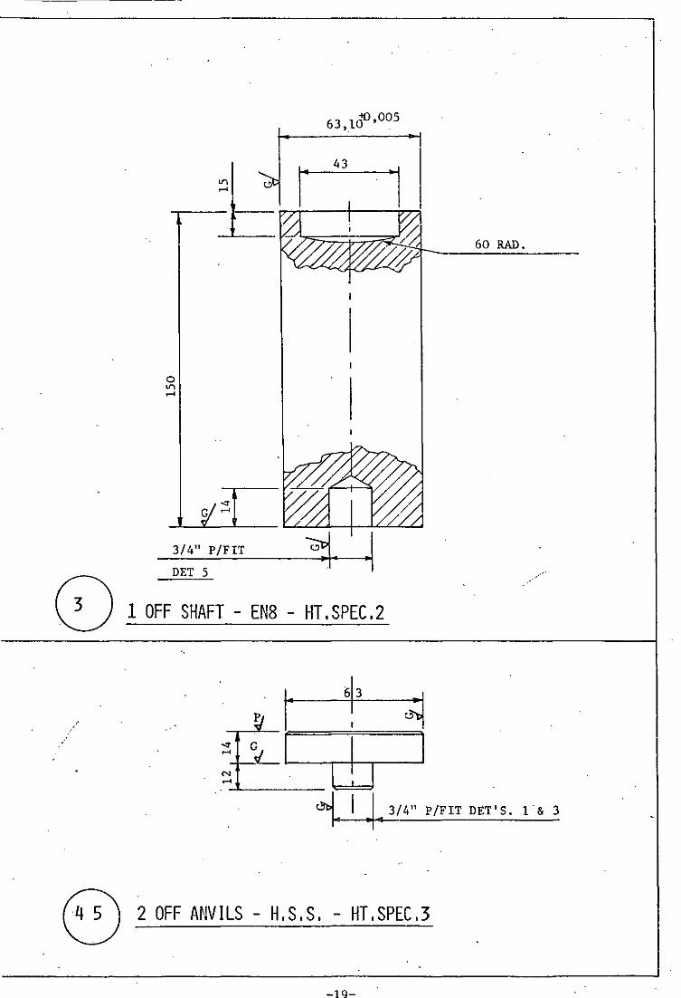
o '" .....
""" G .....
3/4" P/FIT
DET 5
63,1\)0,005
1- ·1
1 OFF SHAFT - EN8 - HT,SPEC,2
N .....
60 RAD.
,. I .143/4" P/FIT DET'S. 1& 3
8 2 OFF ANVILS - ".S .S. - HT. SPEC .3

C/BORE
A
I ~--+-0-
\
/
A
3 HOLES EQUISPACED
ON 120 P.C.D. DRILL 3/8"
CLEARANCE
3/4" P/FIT DET.4
145 TO SUIT 3/8" RSF t------------;D~I"'A---------o~
SECTION ON AA
. (0' 1 OFF BASE - EN25 - HT.SPEC.l
-20-
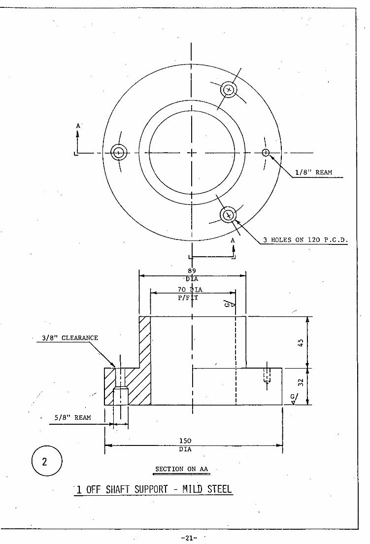
----------------------.---------------------------------------,
3/8" CLEARANCE
~ ~-+-r--,-J
5/8" REAM
+-1 89
'D
70 iIA P/F T
~
150 DIA
SECTION ON AA
I I I
"1 OFF SHAFT SUPPORT - MILD STEEL
-21- "
1/8" REAM
3 HOLES ON 120 P.C.D.
N M
G/
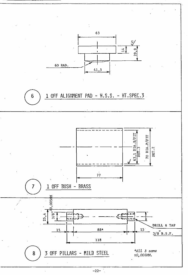
I~ 63
I ·1 ~ . I I I .". '" I ,...,
I I I '" N
60 RAD. /~
0) 1 OFF ALIGNMENT PAD - H.S.S. - HT.SPEC.3
------ -- - -- -_. H H H
'" H -... '" Cl) -... . ~
- - - ;S C') ~ N 0 .
H 0 H ,..., .., .., . -0 0 0
j~ r--
-------------
I· ~I ,
77
0) '.
1 OFF BUSH - BRASS :>: .ri 0 0 -0
T'~E~)~ !-=:~ t .". - -01) N ~""".:~ l~ ~ .
I ~DRILL & TAP
15 88* 15 " T 3/8 B.S.F.
118
G 3 OFF PILLARS - MILD STEEL 'AZZ :5 same ±O,OOSMM •
.
-22-

REAM 3/8"
2 HOLES TAP
2 B.A.
•
I. J J I 63.15- 0,005 29
DIA. 76
DIA.
1 OFF TRANSDUCER SUPPORT - MILD STEEL
im -23-
ApPENDIX II I
AVITZUR'S UPPER BOUND SOLUTION
· .'
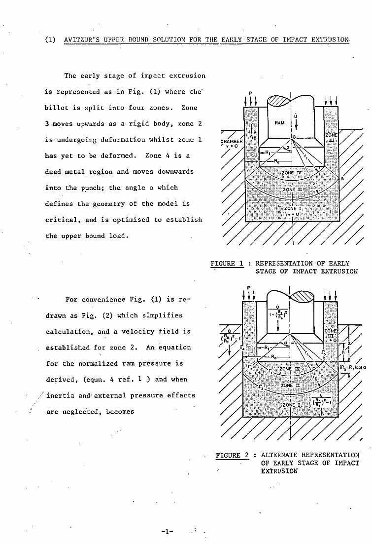
(1) AVITZUR'S UPPER BOUND SOLUTION FOR TilE EARLY STAGE OF IMPACT EXTRUSION
The early stage of impact extrusion
is represented as in Fig. (1) where the"
billet is split into four zones. Zone
3 moves upwards as a rigid body, zone 2
is undergoing deformation whilst zone 1
has yet to be deformed. Zone 4 is a
dead metal region and moves downwards
into the punch; the angle a which
defines the geometry of the model is
critical, and is optimised to establish
the upper bound load.
For convenience Fig. (1) is re-
drawn as Fig. (2) which sImplifies
calculation, and a velocity field is
established for zone 2. p~ equation
for the normalized ram pressure is
derived, (equn. 4 ref. 1 ) and when
inertia and" external pressure effects
are neglec"ted, becomes
-1-
FIGURE 1
FIGURE 2
REPRESENTATION OF EARLY STAGE OF IHPACT EXTRUSION
ALTERNATE REPRESENTATION OF EARLY STAGE OF IHPACT EXTRUSION
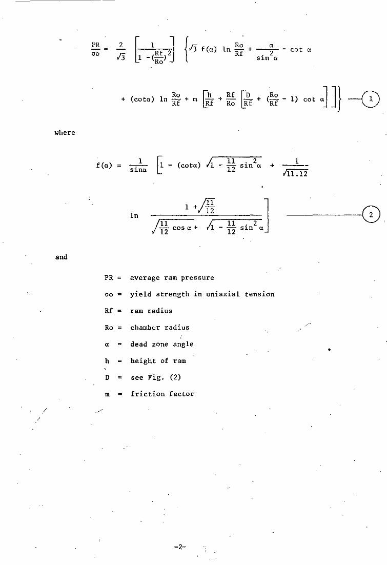
where
and
PR -= 00
2
/3 {/3 f(a) Ro a
in -R-f + -.~2- - cot a S1n ex
Ro + (cota) in Rf + G
h Rf ~D m -+- -+ Rf Ro Rf
(RO _ Rf 1) cot aJ J} -0
f(a) =
PR =
00 =
Rf =
Ro =
a =
h =
D =
m =
. .
1 sinex
ln
G - (cota) Ii.
/IT 1 +/12
j .!.!. cos a + Ii. 12
average ram pressure
11 12
11 12
yield strength in"uniaxial
ram radius
chamber radius
dead zone angle
height of ram
see Fig. (2)
friction factor
-2-
• 2 S1n ex
. 2 ] Sl.n ex
+
tension
1
,111.12
-----,---j(0
•
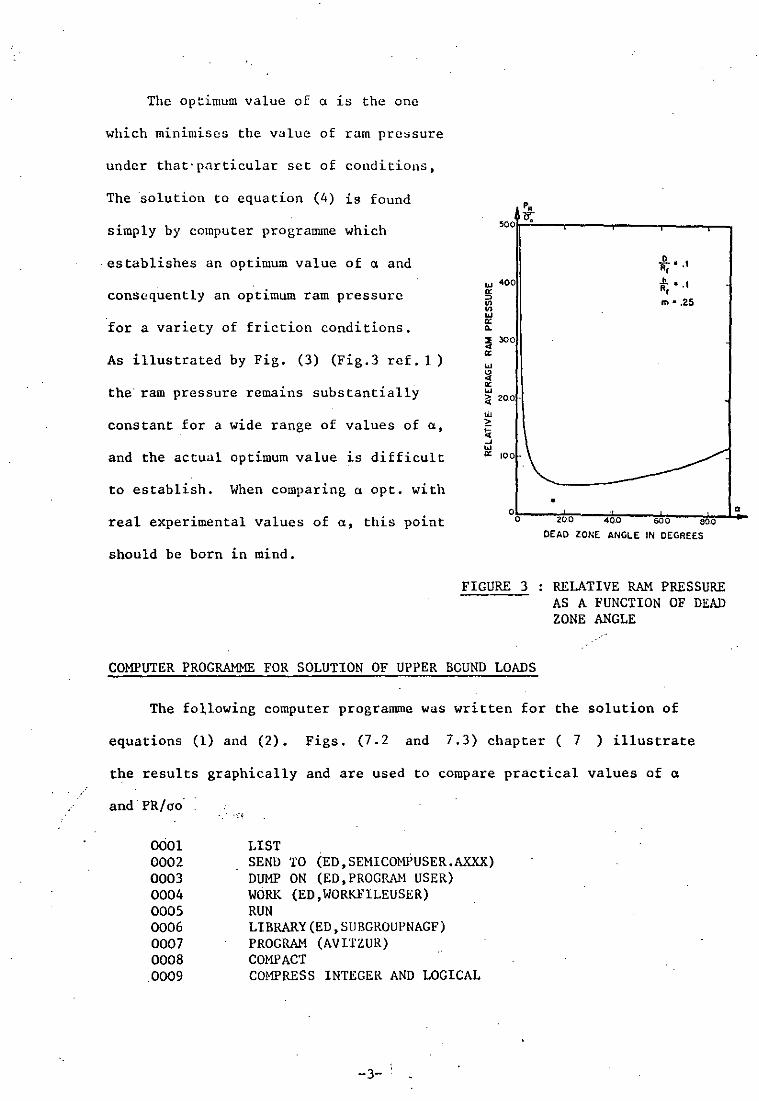
The optimum value of Cl is the one
which minimises the value of ram pre,sure
under that· particular set of conditions,
The solution to equation (4) is found
simply by computer programme which
,establishes an optimum value of Cl and
consequently an optimum ram pressure
for a variety of friction conditions.
As illustrated by Fig. (3) (Fig.3 ref. 1 )
the' ram pressure remains substantially
constant for a wide range of values of Cl,
and the actual optimum value LS difficult
to establish. When comparing Cl opt. with
p.
500 7:T;
liJ 400
~ '" ... a: .. :I 300 a: ... ~ 0: ... ?;( 200
'" > Ei -' ~ 100
•
. o • , ... ii; •. , m· .25
real experimental values of Cl, this point °o~---Tc~--~~--~rn-__ ~~~a .. o 200 40.0 600 60:0
should be born in mind.
FIGURE 3
COMPUTER PROGRAMME FOR SOLUTION OF UPPER BCUND LOADS
DEAD ZONE ANGL.E IN DEGREES
RELATIVE RAM PRESSURE AS A FUNCTION OF DEAD ZONE ANGLE
The fo~lowing computer programme was written for the solution of
equations (1) and (2). Figs. (7.2 and 7.3) chapter ( 7 ) illustrate
the results graphically and are used to compare practical values of Cl
and' PR/ao'
0001 0002 0003 0004 0005 0006 0007 0008
,0009
LIST SEND TO (ED,SEMICOMPUSER.AXXX) DUMP ON (ED,PROGRAH USER) WORK (ED,WO~~ILEUSER) RUN LIBRARY (ED,SlIBGROUPNAGF) PROGRAM (AVITZUR) COMPACT COMPRESS INTEGER AND LOGICAL
-3- '

-------_ ...
0010 0011 0012 0013
0014 0015 0016
INPUT 1 = eRO OUTPUT 2 = LPO TRACE ? END
}IASTER FIRST DUU,NSION RT(12) CON!10N/BLl/RAT,F,DEPTH EXTERNAL FUN READ(1,100) (RT(I),I=1,12)
100 FOR}IAT(FO.O) DO 1 11=1,2 DEPTH=0.1+0.4*(Il-l.) DO 1 12=1,5 F=0.+0.25*(I2-1.) WRITE(2,200) DEPTH,F
200 FOR}IAT(////' NEW VALUES DEPTH = ',F6.2,' I,' RATIO',3X, 'OPT VAL OF ABSP',3X,'ALPHA')
DO 1 I3~l,12 RAT=RT(I3) ALPA=40. XSTEP=10. ABSACC=0.5E-01 RELACC=0.5E-06 MAX=30 IFA=l
F = '.F6.2.//
.0017 0018 0019 0020 0021 0022 0023 0024 0025 0026 0027 0028 0029 0030 0031 0032 0033 0034 0035 0036 0037 0038 0039 0040 0041 0042
CALL E04AAF(ALPA,ABSP,ABSACC,RELACC,XSTEP,FUN,MAX,IFA) IF(IFA.GE.1) WRITE(2,202) TFA
202 FOR}IAT (' PROBLEMS IN OPT. ROUTINE IFA = 1, I 2) WRITE(2,201) RAT,ABSP,ALPA
1 CONTINUE 201 FOR}IAT(/.lX.F6.2,5X,FIO.6,5Y.,F6.2)
STOP END
END OF SEGMENT, LENGTH 164, NAME FIRST
0043 SUBROUTI~~ FUN(ALPA,ABSP) 0044 CONI10N/BL1/RAT,F,DEPTH 0045 PI=3.1415926536 0046 LAND=RAT/25. 0047 FR=0.9166667 0048, DR=0.2998801 0049 RALP=ALPA*PI/180. 0050 SRA=SIN(RALP) 0051 SSRA=SRA*SRA 0052 FAL01./SSRA*(1.-COS(RALP)*SQRT(1.-FR"SSRA)
•
0053 l+DR*ALOG«l.+SQRT(FR»/(SQRT(FR"COS(RALP»+SQRT(l.-FR*SSRA»» 0054 ABSP=2. /SQRT (3.)" (1. -1. / (RAT"RAT») 0055 1* (SQRT(3.)*FAL*ALOG(RAT)+(RALP/SSRA)-COT(RALP)+COT(RALP)*ALOG 00562(RAT)+F*(LAND+1./RAT*(DEPTH+(RAT-1.)*COT(RALP»» 0057 100 FOR}IAT(3(2X,E16.9» 0058 RETURN 0059 END,
-4-:-

(2) SOLUTION ~'OR NOSED RAH
l-'here " dead metal zone prevails, material !!lust shear over
itself, thus increasing the ram pressure. As shear losses are
proportional to 00//3 and friction losses proportional to moo//3
(where m varies between 0 and 1) it is desirable to replace the
flat ram with a nosed ram, the dimensions of which (et) are optimised
to minimise the ram pressure.
In this case equation (1) becomes
PR 2
[ 1 -:!!/J {/3 f(a) In Ro a cot a -= - + 00 /3 Rf 2 . 2 2 S1n a
+ (cota) Ro In Rf + m Gh Rf
Rf + Ro ~+ Rf (Ro _ Rf 1) cot a]
1 G a - cot et] J} 0) +- . 2 2 Sl.n ex
The original computer programme is now modified to accommodate
the changes which result, as follows:-
for lines SS and 56 insert
• SS l*(SQRT(3.)*FAL*ALOG(RAT)+(RALP/SSRA/2.)-COT(RALP)
/2.+COT(RALP)*ALO 56 2G(RAT)+F*(LAND+I./RAT*(DEPTH+RAT-I.)*COT(RALP))
+.5* (RALP/SSRA-COT 57 3(RALP))))
The solutions for both flat and nosed rams are compared in
Fig.(7.4) chapter ( 7 ).
-5-

· (3) AVITZUR' S UPPER BOUND SOLUTION FOR THE FINAL STAGE OF nn'ACT EXTRUSION
Avitzur's equation for the minimum external pressure to prevent
cavitation (equn. 16 ref 30 ) is found to be
P -= 00
where
1 + In(~~)2
+
~ (Ro) 2J Rf
6
G _(~~)2J (2 l(Ro) 2
313
3 Ro 2T
Ro Rf
[H Ro + hJ} ~f Rf RD --~8
P = pressure applied to annular cross section of emerging can
T = distance between ram and bottom of chamber
H = height of chamber wall
and inertia effects are neglected, see .Fig.4.
Where no external pressure is applied, the
value of TIRo becomes critical, and a value of
minimum slug thickness to prevent cavitation
versus reduction and friction can be calculated.
This is plotted in Fig.(7.6) chapter ( 7 ).
FIGURE 4: 2-Z0NE REPRESENTATION OF SOUND FLOW DURING IMPACT EXTRUSION FINAL STAGE
For the solution of equn.(4) let Ploo = 0 and solve for TIRo.
This is done as follows.
let x = Ro/Rf
y = RolT
multiply R.H.S. of equation by Y, then
o = Ay2 + by + C ------------~C)
-6-

--
where A = -
? (l-x") (l+m)
213
2 In(x )
(1-x2) Il = 1 +
C = 2x2(4x-3- b)
x
2m
COMPUTER PROGRAMME FOR SOLUTION OF CAVITATION EQUATION
Equation (5) is simply solved by computer programme as follows
1. 2. 3. 4. 5. 6. 7. 8. 9.
10. 11. 12. 13. 14. 15. 16. 17. 18. 19. 20 •. 21.
22. 23. 24. 25.
1.
MASTER MALAKA Cl=0.3 C2=0.01 DO 1 1=1,2 F=FLOAT fI-1) WRITE(2,200) F DO 1 J=1,20 X=1.+FLOAT(J)/100. XSQ=X*X Xl=1.-XSQ X2=Xl/3./SQRT(3.) A=-1.5*X2*(1.+F) B=1.+ALOG(XSQ)/Xl+6.*F*X2/Xl/Xl*(Cl*X+C2) C=2.*X2*XSQ*(4.*X-3.-l./X/X)/Xl/Xl/Xl c=-c Z=(B*B-4.*A*C) SQR=SQRT(Z) Yl=2.*A/(-B+SQR) Y2=2.*A/(-B-SQR) WRITE(2,20l) X,Yl,Y2
•
200 FOR}~T(////' NEW VALUE OF M = ',F6.2.//.' X=RO/RF T/RO T/ l' , /)
201 FO~~T (/,4(lX,F7,3» 1 CONTINUE
STOP END
FINISH
The solution is plotted graphically in Fig.(7.6) chapter ( 7 ).
-7-
ApPENDIX IV
TABULATED DATA
' ..

TABLE NO. 1
COMPRESSION TEST DATA
SLUG DIMENSIONS: 19.05MM DIA X 19.05MM
SLUG HEIGHT LOAD TRUE STRESS ho/h TRUE STRAIN MEAN YIELD (NN) (KN) cr(N/NN2) e:=Ln ho/h STRESS (j (N/HH2)
18.42 35 119 1.032 0.032 58
17.78 57 188 1.068 0.068 III
16.47 80 244 1.153 0.142 . 166
15.24 98 276 1.250 0.223 210
13.97 114 295 1.362 0.309 232
12.70 130 306 1.500 0.406 248
11.43 150 316 1.664 0.509 261 I
10.16 173 324 1.874 0.628 273
8.89 202 332 2.142 0.760 282
7.62 23, 334 2.500· 0.916 290
6.35 287 336 3.000 1.100 326
5.08 358 336 3.750 1.322 327
3.81 472 336 5.000 1.609 330
-1--".

TABLE NO. 2
RE-LUBRICATED COMPRESSION TtST DATA
PUNCH TRAVEL PUNCH LOAD (MM) (KN)
0.18 42
0.58 59
1. 27 78
2.13 95
3.02 109
4.06 122
4.93 135
5.92 150
7.52 173
7.77 195
8.66 218
9.68 253
10.57 289
11.48 334
12.19 383
13.02 439
13:61 501
-2-

TABLE NO. 3
DATA FOR INDIRECT FLAT PUNCH EXTRUSION
<B I LLET H: D= 1)
EXTRUSION· MAX.PUNCH EXTRUSION PUNCH RATIO LOAD (KN) PRESSURE STRESS Ln(R)
(N/nun2) (N/nun2)
1.19 409 . 208 1300 0.174
1.33 590 301 1200 . 0.285
1.56 808 412 1140 0.445
1.96 1145 584 1190 0.673
2.78 1536 782 1220 1.022 -
./
-3-

TABLE NO, 4
DATA FOR DIRECT FLAT PUNCH EXTRUSION
(BILLET H:D=l)
EXTRUSION -MAX. PUNCH EXTRUSION PUNCH RATIO LOAD (KN) PRESSURE STRES~
(N/nnn2) (N/nnnL)
1.33 625 318 1270
1.56 835 425 1180
1.96 1155 588 1200
2.78 1550 790 1230
-4-
Ln(R)
0.285
0.445
0.673
1.022

,
TABLE NO.S
HOMOGENEOUS DEFORMATION PUNCH LOADS
PUNCH DIA (nun) 20 25 30 35
EXTRUSION RATIO 1.19 1.33 1.56 1. 96
LOG STRAIN e: 0.174 0.285 0.445 0.673 e
2 omeN/nun ) 194 226 254 277
THEORETICAL PUNCH FORCE Lh (KN) 68 131 229 378
OBSERVED PUNCH FORCE Le (KN) 409 590 808 1145
RATIO Lh/Le % 16.7 22.2 28.4 33.1
DATA FROM REFS. (36, )/)
EXTRUSION RATIO 1.43
RATIO Lh/Le %
COPPER* 24.8
EN** 16.2
-5-
1.92
30.8
26.7
2.49 3.37
37.7 42.9
32.8 38.1
*REF(3b)
**REF(37)
40
2.78
1.022
295
612
1536
39.9
.-
5.07
48.0
44.1

TABLE NO, 6
LOADS FOR 12,7MM PUNCH TRAVEL
EXTRUSION RATIO 1. 33 1.56 1.96 2.78
INDIRECT EXTRUSION 515 725 1000 1350
PUNCH LOAD (KN)
DIRECT EXTRUSION 600 825 1100 1500
PUNCH LOAD (KN)
-6-
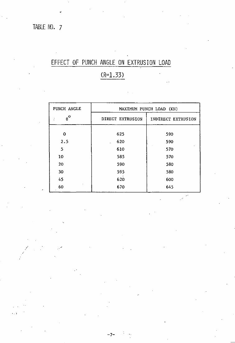
./
'. ,
•
TABLE NO. 7
EFFECT OF PUNCH ANGLE ON EXTRUSION LOAD
(R=1.33)
PUNCH ANGLE MAXIMUM PUNCH LOAD (KN)
eO DIRECT EXTRUSION INDIRECT EXTRUSION
0 625 590
2.5 620 590
5 610 570
10 585 570
20 590 580
30 595 580
45 620 600
60 670 645
-7-

TABLE NO. 8
EFFECT OF BILLET· LENGTH ON PUNCH
AND EJECTION LOADS
BILLET H~D RATIO MAX. PUNCH LOAD MAX EJECTION LOAD (KN) (KN)
0.25 420 16
0.50 515 30
0.75 560 41
1.00 590 64
1.25 600 77
.. -
...-
-8-

TABLE NO, 9
EFFECT OF REDUCTION ON DEAD ZONE ANGLE
WITH FLAT PUNCH
EXPERIMENTAL 0
VALUES Ro/Rf a
2.5 73
2.0 70
1.66 64
COMPUTER RESULT 0 0 a opt a opt
VALUES Ro/Rf (M;l) (M;O)
1.25 46.68 32.23
1.46 52.57 39.83
1.66 59.36 46.25
2.0 64.63 51.93
2.5 68.74 56.95
3.0 70.89 59.96
3.5 72.22 62.04
4.0 73.11 63.55
4.5 73.75 64.70
5'.0 74.22 65.61
5.5 74.59 66.35
6.0 74.91 66.96
-9-
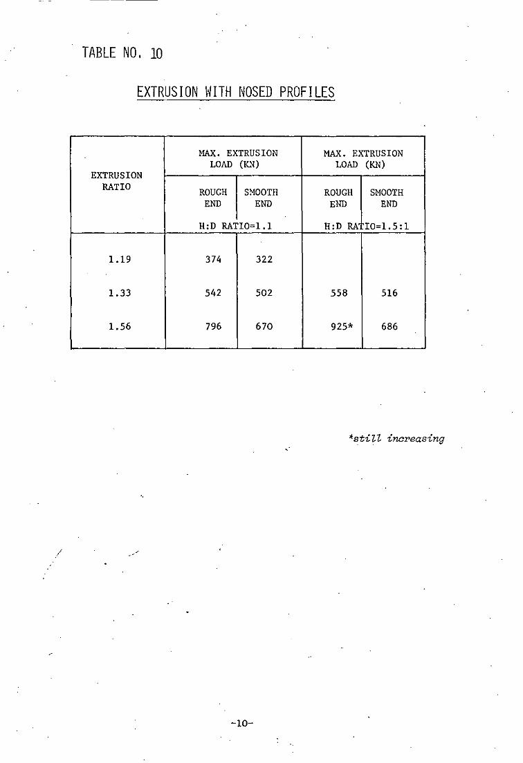
_._---
TABLE NO. 10
EXTRUS ION \~ ITH NOSED PROF I LES
MAX. EXTRUSION MAX. EXTRUSION LOAD (KN) LOAD (KN)
EXTRUSION RATIO ROUGH SMOOTH ROUGH SMOOTH
END END END END
H:D RATIO=1.1 H:D RA 10=1.5:1
1.19 374 322
1.33 542 502 558 516
1.56 796 670 925* 686
"still increasing
./
-10-

TABLE NO. 11
UPPER BOUND RAM PRESSURES FOR EXTRUSION
IHTH FLAT RAM
P h -;0 -;01 00 'Rf •
PR EXPERIMENTAL -Ro 00 VALUES PR Ri 00
m;O m;l
1.25 3.73 4.81 3.08
1.43 3.62 4.43 2.58
1.67 3.71 4.36 2.10
2.00 3.95 4.50 1.86
2.50 4.34 4.82 1.87
3.00 4.71 5.15
3.50 5.06 5.47
4.00 5.37 5.76
4.50 5.65 6.03
5.00 5.91 6.28
5.50 6.15 . 6.51
6.00 6.37 6.72
-11-

TABLE NO. 12
UPPER BOUND RAM PRESSURES FOR EXTRUSION
WITH NOSED RAf1
P -= 0 00 '
h Rf = 0.1
PR OPT.a 0 -Ro 00
Rf m=O m=l m=O m=l
1.25 3.00 4.81 43.81 43.68
1.43 2.97 1,.43 52.47 . 52.57
1.67 3.10 4.36 58.78 59.36
2.00 3.35 4.50 63.55 64.63
2.50 3.76 4.82 67.24 68.74
3.00 4.13 5.15 69.18 70.89
3.50 4.47 5.47 70.43 72.22
4.00 4.78 5.76 71.40 73.11 .
4.50 5.05 6.03 72.11 73.75
5.00 5.31 6.28 72.41 74.22
5.50 5.47 6.51 72.79 74.59
6.00 ., 5.77 6.72 73.11 74.91
-12-

TABLE NO, 13
UPPER BOUND SOLUTION FOR PREVENTION OF CAVITATION
RELATIVE \'IALL SLUG THICY~ESS/CYL.RADIUS THICKNESS Ro/Rf m=O m=l
1.01 0.010 0.001
1.02 0.020 0.003
1.03 0.031 0.006
1.04 0.041 0.010
1.05 0.052 0.016
1.06 0.063 0.022
1.07 0.074 0.030
1.08 0,085 0.038
1.09 0.096 0.047
1.10 0.108 0.057
1.11 0.120 0.068
1.12 0.131 0.079
1.13 0.143 0.091
1.14 0.155 0.103
1.15 0.167 0.115
1.16 0.179 - 0.128
1,17 0.192 0.142
1.18 0.204 0.155
1.19 0.217 0.170
1.20 0.229 0.184
-13-


/