A Study of cavitation induced surface erosion in … · A study of cavitation induced surface...
12
MADADNIA, J, SHANMUGAM, D.K., NGUYEN, T. and WANG, J., A study of cavitation induced surface erosion in abrasive waterjet cutting systems. 2008 Advanced Materials Research Vols. 53-54 (2008) pp 357- 362, online at http://www.scientific.net © (2008) Trans Tech Publications, Switzerland 1 A Study of cavitation induced surface erosion in abrasive waterjet cutting systems J. Madadnia 1,* , D.K. Shanmugam 2 , T. Nguyen 2 and J. Wang 2 1 Faculty of Engineering, University of Technology, Sydney, PO.Box 123, Broadway, NSW 2007, Australia. 2 School of Mechanical and Manufacturing Engineering, The University of New South Wales, NSW 2052, Australia Abstract Current jet cutting systems experience severe nozzle erosion and associated maintenance and downtime costs. An experimental investigation was conducted to qualitatively and quantitatively analyse the generation of cavitation in a high pressure water jet cutting system, and to characterise cavitation induced accelerated surface erosion by slurries. The analysis of surface morphology indicates that the shearing induced by cavitation played a major role in the erosion process. The results promise a feasible solution to reduce nozzle wear, and to enhance material removal in the jet cutting process. Keywords: Cavitation erosion; Abrasive erosion; Submerged high pressure jet; Material removal; Erosion wear; Abrasive waterjet; AWJ. 1. Introduction The high pressure components in the abrasive suspension jet (ASJ) system are severely eroded by the pressurised slurries. In an entrainment abrasive waterjet (AWJ) system, only pressurised water is pumped through the system, and dry-abrasives with air are then admitted into the water, leading to wear in the nozzle or mixing tube. It is therefore important to investigate ways to reduce the wear and to improve cutting efficiency in those systems. The entrained air in a high speed slurry jet can significantly generate mist at the nozzle exit. The mist is harmful if soluble chemicals are added to water to improve cutting performance of the jet and the issue of occupational health and safety needs to be considered [1-4]. The erosion accelerated by cavitation has been investigated in many material handling systems such as vortex-amplifiers [5], conical diffusers [6], valves [7], and low speed waterjet nozzles [8]. These studies have shown that at the condition of liquid flow where tensile forces can induce nucleation of vapour bubbles, the collapse of these bubbles at a higher pressure on a surface * Corresponding Author: Fax: +61 2 9514 2655, E-mail: [email protected] (J. Madadnia).
Transcript of A Study of cavitation induced surface erosion in … · A study of cavitation induced surface...

MADADNIA, J, SHANMUGAM, D.K., NGUYEN, T. and WANG, J., A study of cavitation induced surface erosion in abrasive waterjet cutting systems. 2008 Advanced Materials Research Vols. 53-54 (2008) pp 357-362, online at http://www.scientific.net © (2008) Trans Tech Publications, Switzerland
1
A Study of cavitation induced surface erosion
in abrasive waterjet cutting systems
J. Madadnia1,*, D.K. Shanmugam2, T. Nguyen2 and J. Wang2 1 Faculty of Engineering, University of Technology, Sydney, PO.Box 123, Broadway, NSW 2007, Australia.
2 School of Mechanical and Manufacturing Engineering, The University of New South Wales, NSW 2052, Australia
Abstract
Current jet cutting systems experience severe nozzle erosion and associated maintenance and
downtime costs. An experimental investigation was conducted to qualitatively and quantitatively
analyse the generation of cavitation in a high pressure water jet cutting system, and to
characterise cavitation induced accelerated surface erosion by slurries. The analysis of surface
morphology indicates that the shearing induced by cavitation played a major role in the erosion
process. The results promise a feasible solution to reduce nozzle wear, and to enhance material
removal in the jet cutting process.
Keywords: Cavitation erosion; Abrasive erosion; Submerged high pressure jet; Material
removal; Erosion wear; Abrasive waterjet; AWJ.
1. Introduction
The high pressure components in the abrasive suspension jet (ASJ) system are severely eroded
by the pressurised slurries. In an entrainment abrasive waterjet (AWJ) system, only pressurised
water is pumped through the system, and dry-abrasives with air are then admitted into the water,
leading to wear in the nozzle or mixing tube. It is therefore important to investigate ways to
reduce the wear and to improve cutting efficiency in those systems. The entrained air in a high
speed slurry jet can significantly generate mist at the nozzle exit. The mist is harmful if soluble
chemicals are added to water to improve cutting performance of the jet and the issue of
occupational health and safety needs to be considered [1-4].
The erosion accelerated by cavitation has been investigated in many material handling systems
such as vortex-amplifiers [5], conical diffusers [6], valves [7], and low speed waterjet nozzles
[8]. These studies have shown that at the condition of liquid flow where tensile forces can induce
nucleation of vapour bubbles, the collapse of these bubbles at a higher pressure on a surface
* Corresponding Author: Fax: +61 2 9514 2655, E-mail: [email protected] (J. Madadnia).

MADADNIA, J, SHANMUGAM, D.K., NGUYEN, T. and WANG, J., A study of cavitation induced surface erosion in abrasive waterjet cutting systems. 2008 Advanced Materials Research Vols. 53-54 (2008) pp 357-362, online at http://www.scientific.net © (2008) Trans Tech Publications, Switzerland
2
result in severe surface erosion. This phenomenon has also been studied in high pressure waterjet
cutting devices and a significant improvement in the cutting performance was found by utilizing
cavitation, whereby the cutting depths were increased by 100% and 500% when cavitation was
induced by the water-sheathing, and by the fully submerged water jet, respectively [9]. However,
these studies did not consider cavitation effect in AWJ. Consequently, there has been insufficient
knowledge for an improved system design so as to reduce nozzle erosion, while making use of
cavitation to increase the material removal rate.
In this study, an experimental system was developed and used to induce cavitation in a fully
submerged, high pressure waterjet in slurries. An analysis was then carried out to explore the
mechanism of the accelerated surface erosion and the effect of cavitation on the surface erosion.
2. Experiment
The schematic diagram of experimental setup is illustrated in Fig. 1. Water was pumped through
the system at a pressure of 240MPa using a high intensifier pumping system (Model 5X-60 from
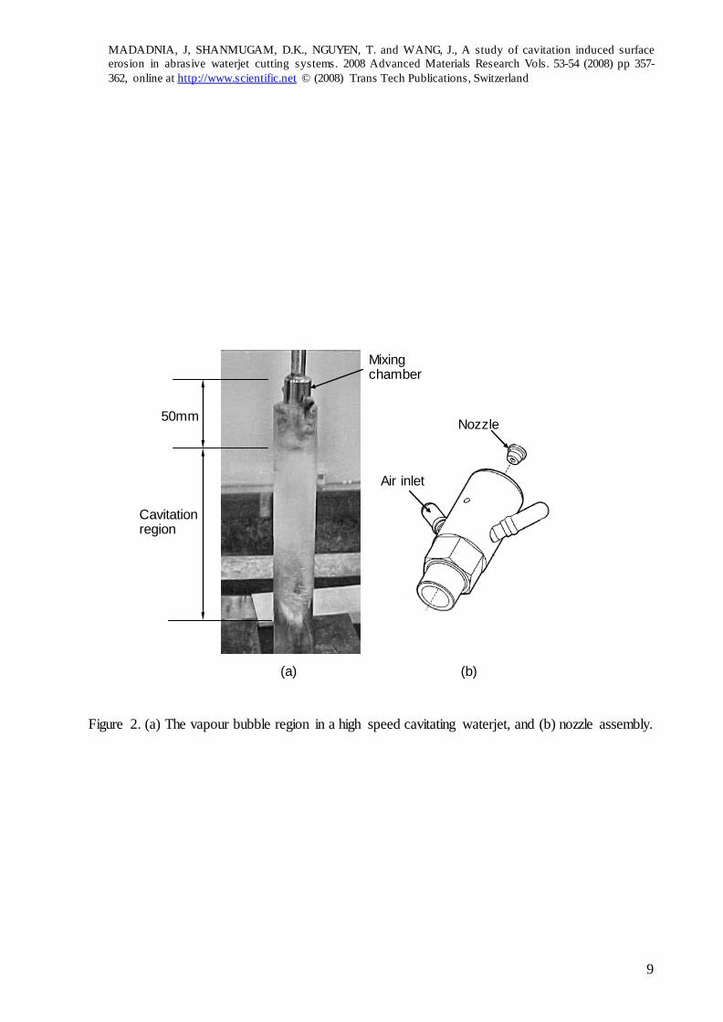
Flow). Fig. 2(a) shows the vapour bubble cavitating region and Fig. 2(b) shows the nozzle
assembly where an orifice of 0.254mm in diameter was used as a waterjet nozzle to generate a
waterjet. The nozzle was positioned at the inlet of the mixing chamber, so a fixed stand-off
distance of 50mm could be maintained. The jet was directed tangentially to the target surface, so
the full extend of jet erosion can be studied. The nozzle and the specimen were fully submerged
into a slurry solution containing mesh 80 garnet abrasives with the average size of 180μm, at a
concentration of 90% by weight. The specimen, slurry and the waterjet were enclosed in a tubular
shaped chamber made from perspex to enable observation. Commercial aluminium specimens with
the module of elasticity, E = 70GPa, and Poisson ratio, υ =0.35 were selected because of its high
erosion rate and its distinguishable surface characteristics exhibited under different experimental
conditions. All the experiments were conducted at a fixed pressure in the following two conditions:
(a) Non-cavitating waterjet in which atmospheric air was introduced inside the mixing chamber
by the vacuum action of the high speed jet and expanding as two to three large air bubbles,
preventing the formation of vapour bubbles and cavitation; and
(b) Cavitating waterjet in which the mixing chamber was sealed from air; and by this way, the
tensile force and vacuum generated by the high speed jet induced nucleation of an infinite
number of tiny vapour bubbles, forming a milky cloud in the jet boundary layer. In general,

MADADNIA, J, SHANMUGAM, D.K., NGUYEN, T. and WANG, J., A study of cavitation induced surface erosion in abrasive waterjet cutting systems. 2008 Advanced Materials Research Vols. 53-54 (2008) pp 357-362, online at http://www.scientific.net © (2008) Trans Tech Publications, Switzerland
3
the region which cavitation bubbles collapse on the aluminium specimen, and the speed of
waterjet, could be controlled by the pump pressure.
The material removed was determined by weighting of the specimen before and after each
experiment. Surface morphology of the specimens was inspected and analysed using a 3D digital
microscope (Keyence VHX-100).
3. Results and Discussion on Material Removal Mechanisms
Fig. 2 shows the milky cloud representing the cavitation region inside the perspex chamber. It was
noticed that the nucleated vapour bubbles gradually disappeared in the cavitation region before
reaching to the free surface, as bubbles diffused away from the jet, and as the jet is slowed down
by slurries and the specimen. It is believed that the vapour bubbles were in a sub-cooled and
metastable condition and their collapse was accompanied with condensation shock and the water
hammer effects, resulting in an accelerated surface erosion on the specimen, especially in
slurries, as reported in [10, 11]. It is also noticed that the diameter and the divergent angle of the
jet increased when cavitated. The cavitation range determines the effective distance where
cavitation may enhance material removal or cause severe wear on the mixing tube in AWJ
systems.
Figs. 3(a) and 3(b) illustrate two aluminium specimens exposed for 180 seconds under the testing
conditions of (a) and (b) described earlier in Section 2. In Fig. 3(a), the cutting zone is
characterised by the features that are often found in erosion by a non-cavitating abrasive
waterjet, that is, it contains a cutting wear zone and a deformation wear zone. Material removal
within the deformation wear region occurs through a cyclic cutting action and commonly results in
a wavy surface texture which serves as the division between the cutting wear and deformation wear
regions as reported in [12,13]. A further examination of the surface structure of the sample under
condition (a) shows a pit-like surface with shear lips, indicating the high plastic deformation on the
surface. This confirms that an extensive plastic deformation has contributed to the high residual
strength and rapid degradation of this hardening behavior as the depth of subsurface is increased. In
this mode, material is locally work-hardened with continual bombardment of waterjet, and
eventually removed by ploughing. The ‘‘deformation wear zone’’ in this cutting exists below the
cutting wear zone and is typically identified by waviness or striation patterns caused by severe jet
deflections.

MADADNIA, J, SHANMUGAM, D.K., NGUYEN, T. and WANG, J., A study of cavitation induced surface erosion in abrasive waterjet cutting systems. 2008 Advanced Materials Research Vols. 53-54 (2008) pp 357-362, online at http://www.scientific.net © (2008) Trans Tech Publications, Switzerland
4
Fig. 3(b) shows the erosion pattern. In the cutting wear zone, the eroded pattern is associated
with a larger bore than that in Fig. 3(a), while outside the cutting wear zone it has a smoother
surface polished by the multidirectional impacts and bombardments of the cavitating- induced
micro-jets. The weight-loss in the specimens was at least 10% higher than in case (a) with no
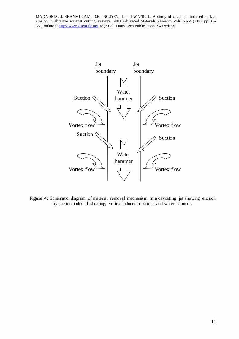
cavitation. Fig. 4 shows the sketch of three types of accelerated material removal mechanisms in
the cavitating conditions, i.e. suction induced shearing, vortex induced micro-jets, and water
hammer. These are analysed below.
3.1 Suction induced shearing
Surface morphology of the cut specimens are shown in Figs. 5(a) and (b). It can be realized that
the erosion mechanism in the case of Fig. 5(b) is characterized by shearing with little
deformation wear. In fact, the dominant type of material removal mechanism is by suction
induced shearing due to the material’s high ductility. When the high velocity jet was focused
near parallel to the surface, the pressure difference between the jet and the slurry in the container
produced a shear layer. The pressure difference created by the suction was high enough to infuse
(suction) the slurry into the waterjet as shown in Fig. 4. The high speed jet eventually developed
into an abrasive waterjet to which the presence of abrasives in the slurry generated shear force
that caused the material to be removed by shearing. The surface as observed in Fig. 5(b)
possesses fine-scale morphology as compared that in Fig. 5(a); this substantiates that the erosion
process involved an extensive mechanical deformation.
3.2 Vortex induced microjet
Another feature of the erosion produced by the cavitating waterjet is the pitting on the metal surface
outside the effective jet cutting circumference or jet boundary, as shown in Fig. 4. The pitting is
combined with highly directional suction induced shearing. It seems that a spiral vortex was
generated around the high speed jet submerged inside the still solution. Bubbles were generated
around the waterjet and collapsed inside the vortex spiral. When comparing the erosion patterns in
Fig. 5(a) (no-cavitation) with that in Fig. 5(b) (with cavitation), it can be seen that the pits are more
pronounced in the former case. This observation evidences the formation and collapse of vapour
bubbles that results in microjets to erode the metal surfaces.
This type of surface pits are generated when a bubble in the flowing liquid collapses in a location
close to the metal surface. To quantify, an average “pit density” of the surface exposed to the
microjet induced by bubble collapse was measured and it was found to be around 60pits/mm2. The

MADADNIA, J, SHANMUGAM, D.K., NGUYEN, T. and WANG, J., A study of cavitation induced surface erosion in abrasive waterjet cutting systems. 2008 Advanced Materials Research Vols. 53-54 (2008) pp 357-362, online at http://www.scientific.net © (2008) Trans Tech Publications, Switzerland
5
occurrence of pitting is dependent on the velocity of the microjet and exposure time and strongly
attenuated by the waterjet. When the microjet impacts on the material surface, material plastic
deformation combined with erosion takes place, and pitting is produced in the material surface.
Theoretically, the diameter of the pitting is related to the size of the microjet which, in turn, is
proportional to the diameter of the incident bubble.
3.3 Water hammer
Water hammer damage was produced on the specimen where bubbles in the liquid collapsed within
a very short proximity of the solid surface, and consequently the generated microjets from the
bubbles impacted on the surface. It may be explained that the fixed cavity is quasi-static and goes
through a cyclic process of formation and collapse. The collapse is due to the production of a re-
entrant jet in the cavity closure region. The energy released by the collapse of the bubbles during
cavitation makes the surface plastic resulting in abrasive-embedment on the surface. Concurrently,
small travelling bubbles become entrained within the jet and together collide with the specimen at
high impact pressure to create the erosion region. The specific occurrence region of water hammers
is shown schematically in Fig. 4.
When observing Figs. 5(a) and (b), pitting is prominent in Fig. 5(b) with larger diametric pits.
However, Fig 5(a) also exhibits a substantial amount of pitting with smaller diameter. This may be
attributed to the fact that the main material removal mechanism of the waterjet without cavitation is
by plastic deformation. When material is removed by plastic deformation, the material tends to chip
away causing micro-cracks at the broken chip area. This phenomenon is also common in shearing
mode (waterjet with cavitation), however it was not possible to distinguish between the pitting
caused by water hammer and micro-cracks caused by chip breaking.
Cavitation by slurry jet involves fluid, erodent particles, and target material. Their properties are
therefore important in better understanding the erosion mechanisms. There have been attempts to
quantify the erodent trajectories and the fluid properties in high velocity jet [14], but the correlation
of such studies to the materials response to erosion still seems remote.
4. Conclusions
Material removal by the motion of a cavitation liquid has been found to be predominantly
influenced by suction induced shearing. A higher material removal rate can be obtained when
cavitation is generated in a submerged waterjet system. The understanding of this work

MADADNIA, J, SHANMUGAM, D.K., NGUYEN, T. and WANG, J., A study of cavitation induced surface erosion in abrasive waterjet cutting systems. 2008 Advanced Materials Research Vols. 53-54 (2008) pp 357-362, online at http://www.scientific.net © (2008) Trans Tech Publications, Switzerland
6
guaranties further studies to use the cavitation phenomenon to increase the material removal rate
in abrasive jet processing or to reduce the nozzle wear for this technology.
References
[1] G.W. Howells, Polymerblasting with Super-Water from 1974 to 1989: a Review,
International Journal of Waterjet Technology 1, (1990) 1-16
[2] L. Bayvel and Z. Orzechowski, Liquid atomization, Combustion - An International
series, Taylor and Francis, (1993).
[3] J. Bardin, E.A. Eisen, S.R. Woskie, R.R. Monson, T.J. Smith, P. Tolbert, K. Hanmond,
and M. Hallock, Mortality studies of machining fluid exposure in the automobile
industry: A case-control study of pancreatic cancer, American Journal of Industrial
Medicine 32 (1997) 240-247
[4] V.R. Mariani, Effect of viscosity of solid-liquid mixture on pump cavitation Bethlehem,
Pa.: Fritz Laboratory, Lehigh University, (1966).
[5] J. Madadnia and I. Owen, Accelerated surface erosion by cavitating particulate- laden-
flows, Wear, 165, (1993) 113-116
[6] J. Madadnia and I. Owen I, Erosion in conical diffusers in particulate- laden cavitating
flow, Int. Jour of Multi-Phase Flows 21 (1995) 1253-1257.
[7] I. Owen and J. Madadnia Valve Erosion In Particulate-Laden Cavitating Flow, ASME
FED- 226 (1995) 59-62.
[8] J. Madadnia,and J. Reizes, Feasibility Studies using cavitation to reduce nozzle erosion in
particulate-laden water jet cutting devices, Abrasive Technology - Current Development
and Application I, J. Wang et al. (Eds), World Scientific, Sigapore, (1999) 299-305.
[9] G.W. Vickers, F.W.Harrison, R.Houlston, Extending the range of Cavitation cleaning
jets, paper J1, 5th International Symposium on Jet Cutting Technology, Honover,
Germany, June 1980, 403-412
[10] T. Momma and A. Lichtarowicz, Some experiments on cavitation damage produced by a
submerged jet, Proceedings of 2nd ASME-JSME Nuclear Joint Conf. (1993) 877-884.
[11] Z. Sun, X.Q. Kang, and X.H. Wang, Experimental system of cavitation erosion with
water-jet, Materials & Design 26(1) (2005) 59-63.
[12] D. Arola and M. Ramulu, Mechanisms of material removal in abrassive waterjet
machining of common aerospace materials, Proceedings of 7th American waterjet
conference 1 (1993) 43-64.

MADADNIA, J, SHANMUGAM, D.K., NGUYEN, T. and WANG, J., A study of cavitation induced surface erosion in abrasive waterjet cutting systems. 2008 Advanced Materials Research Vols. 53-54 (2008) pp 357-362, online at http://www.scientific.net © (2008) Trans Tech Publications, Switzerland
7
[13] M. Hashish, A model for abrassive-waterjet (AWJ) machining, Transactions of ASME
111 (1989) 154-162.
[14] H. Liu, J. Wang, N. Kelson and R.J. Brown, A study of abrasive waterjet characteristics
by CFD simulation. Journal of Materials processing Technology 153-154 (2004) 488-
493.

MADADNIA, J, SHANMUGAM, D.K., NGUYEN, T. and WANG, J., A study of cavitation induced surface erosion in abrasive waterjet cutting systems. 2008 Advanced Materials Research Vols. 53-54 (2008) pp 357-362, online at http://www.scientific.net © (2008) Trans Tech Publications, Switzerland
8
Figure 1. The schematic diagram of the experimental setup.
Air Nozzle
Pump FLOW 5X-60
Test sample
Slurry solution
MADADNIA, J, SHANMUGAM, D.K., NGUYEN, T. and WANG, J., A study of cavitation induced surface erosion in abrasive waterjet cutting systems. 2008 Advanced Materials Research Vols. 53-54 (2008) pp 357-362, online at http://www.scientific.net © (2008) Trans Tech Publications, Switzerland
9
Figure 2. (a) The vapour bubble region in a high speed cavitating waterjet, and (b) nozzle assembly.
Cavitation region
50mm
Air inlet
Nozzle
(a) (b)
Mixing chamber

MADADNIA, J, SHANMUGAM, D.K., NGUYEN, T. and WANG, J., A study of cavitation induced surface erosion in abrasive waterjet cutting systems. 2008 Advanced Materials Research Vols. 53-54 (2008) pp 357-362, online at http://www.scientific.net © (2008) Trans Tech Publications, Switzerland
10
(a) (b) Figure 3. Erosion on 10mm×180mm aluminium samples after 180 seconds operated at pressure of 240MPa using a jet with diameter of 0.254mm: (a) by air-entrained waterjet (no-cavitation) and (b) by vapour-entrained cavitating waterjet.
MADADNIA, J, SHANMUGAM, D.K., NGUYEN, T. and WANG, J., A study of cavitation induced surface erosion in abrasive waterjet cutting systems. 2008 Advanced Materials Research Vols. 53-54 (2008) pp 357-362, online at http://www.scientific.net © (2008) Trans Tech Publications, Switzerland
11
Figure 4: Schematic diagram of material removal mechanism in a cavitating jet showing erosion by suction induced shearing, vortex induced microjet and water hammer.
Vortex flow Vortex flow
Suction
Suction
Vortex flow Vortex flow
Suction
Suction
Water hammer
Water hammer
Jet boundary
Jet boundary

MADADNIA, J, SHANMUGAM, D.K., NGUYEN, T. and WANG, J., A study of cavitation induced surface erosion in abrasive waterjet cutting systems. 2008 Advanced Materials Research Vols. 53-54 (2008) pp 357-362, online at http://www.scientific.net © (2008) Trans Tech Publications, Switzerland
12
(a)
(b)
Figure 5. Surface morphology of aluminium samples eroded by (a) air-entrained waterjet without cavitation, and (b) vapour-entrained cavitating waterjet. Operating conditions are as per in Fig. 3. Noting on shearing mode of material removed within the jet boundary and larger pits outside the
boundary in (b) compared to (a).
![Experimental Research on Cavitation Erosion Detection Based on … · 2012-10-09 · estimate cavitation erosion by observing the removal of the paint [3]. They detect cavitation](https://static.fdocuments.in/doc/165x107/5e93bba127dcb37304714469/experimental-research-on-cavitation-erosion-detection-based-on-2012-10-09-estimate.jpg)


![Evaluation of cavitation erosion resistance of Al-Si ...€¦ · cavitation erosion models based on bulk mechanical properties [11-13] were performed in order to predict the erosion](https://static.fdocuments.in/doc/165x107/602fbc102d0fbb7b2944c54a/evaluation-of-cavitation-erosion-resistance-of-al-si-cavitation-erosion-models.jpg)