
A STUDY OF CASE BASED REASONING APPLIED TO ... STUDY OF CASE BASED REASONING APPLIED TO WELDING...
68
A STUDY OF CASE BASED REASONING APPLIED TO WELDING COMPUTER AIDED FIXTURE DESIGN by Shaun Price A Thesis Submitted to the Faculty of the WORCESTER POLYTECHNIC INSTITUTE In partial fulfillment of the requirements for the Degree of Master of Science in Mechanical Engineering by ________________________________________ May 2009 APPROVED: ____________________________________ __________ Dr. Yiming (Kevin) Rong, Advisor ______________________________________________ Dr. Mustapha Fofana, Thesis Committee Member ____________________________________ __________ Dr. Richard Sisson, Thesis Committee Member ______________________________________________ Dr. Cosme Furlong, Graduate Committee Representative
Transcript of A STUDY OF CASE BASED REASONING APPLIED TO ... STUDY OF CASE BASED REASONING APPLIED TO WELDING...
A STUDY OF CASE BASED REASONING APPLIED TO WELDING COMPUTER AIDED FIXTURE DESIGN
by
Shaun Price
A Thesis
Submitted to the Faculty
of the
WORCESTER POLYTECHNIC INSTITUTE
In partial fulfillment of the requirements for the
Degree of Master of Science
in
Mechanical Engineering
by
________________________________________
May 2009
APPROVED:
____________________________________ __________
Dr. Yiming (Kevin) Rong, Advisor
______________________________________________
Dr. Mustapha Fofana, Thesis Committee Member
____________________________________ __________
Dr. Richard Sisson, Thesis Committee Member
______________________________________________
Dr. Cosme Furlong, Graduate Committee Representative

i
Abstract
This thesis focuses on the application of case based reasoning (CBR) to welding fixtures in a
computer aided design (CAD) environment. Modular fixtures have become more popular in previous
years due to the creation of flexible manufacturing systems. Modular fixtures, since they are composed
of many standardized parts, require much iteration to produce a full fixture design. This process is made
more complicated when it is applied to more complex parts such as welding assemblies. In an effort to
simplify fixture design for such complicated parts, researchers have been working on integrating fixture
design into CAD packages. These efforts, generally known as computer aided fixture design (CAFD), do
not focus on the transition of experience from more experienced designers but only provide a structure
and a virtual environment to create fixtures. The research presented in this thesis will apply to this area.
Case based reasoning (CBR) is a method of using previous cases to help aid the development of
solutions to new problems. Applied to CAFD, this method is reduced to the application of a database
and a retrieval and adaptation system. Current research on CAFD and CBR is limited to only proposing
systems for machining fixtures. This thesis presents a methodology of a CAFD and CBR system that is
dedicated to welding assemblies and fixtures. The focus is on creating an indexing system that
adequately represents the workpiece and fixture, a retrieval system that accurately recovers the
previous cases, and a method that integrates designer feedback in each process. The results of this
thesis will be shown in a case study using an automobile muffler fixture assembly to define each idea of
the methodology and to provide an example.

ii
Acknowledgements
I would like to thank Professor Yiming Rong for his ceaseless efforts to help make my unusual five
year B.S./M.S. thesis possible. I would not have been able to even fathom the possibility of completing
my thesis without his guidance and encouragement. I would also like to thank him for his advice during
my undergraduate years and suggesting that I pursue the B.S./M.S. program.
I am very grateful and would like to thank Dr. Hua Li for his aid and help during my early thesis
work. I learned very much under his tutelage and, without his belief in me and my ideas, I would have not
have had the confidence I have now.
I would also like to express my gratitude to Dr. Hui Wang for allowing me to build off of his
previous research, and for his guidance in shaping my ideas and strengthening them with his expertise. I
would also like to thank him for going above and beyond what was needed to help and sincerely making
sure that I understand the ideas he was proposing, and providing a critical ear to my suggestions.
I thank all the members of my thesis committee, Professor Cosme Furlong, Professor Mustafa
Fofana, and Professor Richard Sisson for their time and assistance in this process.
Finally, I would like to thank Barbara Edilberti for all her help throughout the 5 year B.S./M.S.
process and for working very hard and quickly to make sure that everything was all set concerning my
graduation requirements.

iii
Table of Contents
Abstract .......................................................................................................................................................... i
Acknowledgements ....................................................................................................................................... ii
List of Figures ................................................................................................................................................ v
1. Introduction ............................................................................................................................................. 1
1.1. Background ....................................................................................................................................... 2
1.1.1. Flexible Fixturing ........................................................................................................................ 3
1.1.2. Modular Assembly Fixtures ........................................................................................................ 4
1.1.3. Fixture Design............................................................................................................................. 5
1.2. Current Research and Trends ............................................................................................................ 8
1.3. Thesis Objective ................................................................................................................................ 8
1.4. Thesis Contents ................................................................................................................................. 9
2. Literature Review ................................................................................................................................... 10
2.1. Computer Aided Fixture Design ...................................................................................................... 10
2.1.1. Optimizing fixture locations ..................................................................................................... 11
2.1.2. Verification ............................................................................................................................... 12
2.2. Intelligent Methods ......................................................................................................................... 14
2.2.1. Case based Reasoning .............................................................................................................. 14
2.2.2. Current Research on Case Based Reasoning ............................................................................ 16
2.3. Summary of Problem and Current research ................................................................................... 17
3. Proposed Methodology.......................................................................................................................... 19
4. Case Representation and Retrieval ........................................................................................................ 24
4.1. Fixture Design Case Information Modeling..................................................................................... 24
4.1.1. Conceptual Design ................................................................................................................... 25
4.1.2. Workpiece-fixture system ........................................................................................................ 26
4.1.3. XML representation ................................................................................................................. 31
4.2. Fixture Design Case Retrieval .......................................................................................................... 32
4.2.1. Similarity Analysis..................................................................................................................... 33
4.2.2. Weighting ................................................................................................................................. 33
4.3. Retrieval System .............................................................................................................................. 34
4.4. Interface .......................................................................................................................................... 35
iv
5. Case Studies ........................................................................................................................................... 40
5.1. Muffler Case .................................................................................................................................... 40
5.1.1. Case Information ...................................................................................................................... 42
5.2. Indexing ........................................................................................................................................... 47
5.3. Retrieval and Modification .............................................................................................................. 50
6. Conclusion and Recommendations ........................................................................................................ 55
Bibliography ................................................................................................................................................ 56
Appendix A. XML representation of a sample fixturing solution ............................................................... 59

v
List of Figures
Fig. 1. Bluco modular welding fixture components (Ellig, 2008). ................................................................ 4
Fig. 2. Fixture Design Process (Wang & Rong, 2008). .................................................................................. 6
Fig. 3. 3-2-1 Locating Scheme example. (Carr Lane Manufacturing Co., 2008). .......................................... 7
Fig. 4. Computer Aided Fixture Design Verification system (Kang & Rong, 2001)..................................... 13
Fig. 5. Flow chart of interpretive and problem solving CBR. (Leake, 1996). .............................................. 15
Fig. 6. A general idea of the proposed methodology. ................................................................................ 20
Fig. 7. – Case Retrieval Flowchart. .............................................................................................................. 22
Fig. 8. Information modeling and representation flow chart. ................................................................... 24
Fig. 9. Indexing Decomposition Structure. ................................................................................................. 27
Fig. 10. Varying fixture configurations for the four main types of workpieces (Bluco Co., 2008). ............ 28
Fig. 11. Example of a Supergraph (Wang & Rong, 2008). .......................................................................... 29
Fig. 12. Example of a visual supergraph. .................................................................................................... 30
Fig. 13. Single Function, Multiple Function, and Locator/Clamp Fixture Units respectively (Caterpillar,
Inc.). ............................................................................................................................................................ 31
Fig. 14. XML Script for Fixture Setup .......................................................................................................... 32
Fig. 15. Search dialogue box....................................................................................................................... 36
Fig. 16. First stage of CBR dialogue box ..................................................................................................... 37
Fig. 17. Supergraph import dialogue .......................................................................................................... 38
Fig. 18. Second stage of CBR dialogue box................................................................................................. 39
Fig. 19. Thrush welded muffler case (HSPN news, 2007). ......................................................................... 40
Fig. 20. First example of a dedicated muffler welding fixture (Peterson Jig and Fixture, 2007). .............. 41
Fig. 21. Second example of a dedicated muffler welding fixture (Peterson Jig and Fixture, 2007)........... 42
Fig. 22. Case 1 – Flowmaster 60 series Cross Flow muffler (Flowmaster, Inc., 2009). .............................. 43
Fig. 23. Case 2 – Flowmaster brand 40 series muffler (Flowmaster, Inc., 2009). ...................................... 43
Fig. 24. Case 2 Supergraph. ........................................................................................................................ 44
Fig. 25. Case 2 Fixturing Solution. .............................................................................................................. 45
Fig. 26. Case 3 Flowmaster 80 series Cross Flow muffler (Flowmaster, Inc., 2009). ................................. 45
Fig. 27. Supergraph of Case 3. .................................................................................................................... 46
Fig. 28. Case 3 Fixturing Solution. .............................................................................................................. 47
Fig. 29. 1ST level case retrieval (by workpiece information)....................................................................... 50
Fig. 30. 2nd level case retrieval (matching supergraph of fixturing configuration). ................................... 52
Fig. 31. The new workpiece’s supergraph. ................................................................................................. 52
Fig. 32. The supergraph of matched case (case 2). .................................................................................... 53
Fig. 33. Final fixturing solution for new workpiece .................................................................................... 54
1
1. Introduction
In these troubling economic times, companies are trying to find methods to optimize the
production and utilization of their assets. Now more than ever, companies are trying to manufacture
and fabricate their goods as cheaply as possible by maintaining high production variability and
sustaining low error counts. Additionally, companies are asking younger, less experienced workers to
manage projects that are typically selected for more experienced engineers to maintain the knowledge,
while reducing the number of workers. The sudden shift in industry has caused additional focus on cost
cutting devices and tools that facilitate the acquisition of and maintenance of company specific
knowledge and experience from engineer to engineer.
An example of a cost cutting device is a fixture. A fixture is a tool that is used to accurately
locate and hold a workpiece in a manufacturing or fabrication process. Fixtures can have applications in
machining, assembly, and turning. Fixtures are made for easy loading and unloading and guarantee that
a workpiece can be held in the same location repeatedly with minimal variation. The time needed for
the fabrication process is reduced and costs are lowered by diminishing the need of potential rework on
parts. The focus of this thesis is on welding fixtures which are a type of assembly fixture. These fixtures
are made specifically to hold multiple parts together, allow adequate tool passage, resist high heat and
sputter, permit passage of weld runoff, and in some cases conduct electricity and provide grounding.
Fixture design has much to do with experience, which the younger engineers generally have
been unable to acquire. It can take engineers many years to learn the nuances of the craft. Fixture
design can be dived into four major steps, setup planning, fixture planning, fixture unit design and
verification. These steps can be generalized as analyze the part, define suitable locating and clamping
points, identify tooling and environmental requirements, and create a fixture to satisfy criteria. These
steps can be highly subjective and can require an exhaustive trial an error approach until experience is

2
gained. Fixture design can require weeks to months depending on the experience of the designer.
When mistakes are made more time is required and the resulting large number of iterations means
higher cost.
Computers have dramatically reduced the design process time. The application of computers to
fixture design is called computer aided fixture design (CAFD). By using a computer, designers are able to
design in a virtual atmosphere. This helps the designers identify potential problems and undertake
different ideas without actually physically creating the fixture. These programs have the added benefit
of keeping a designer from missing steps while designing, and by avoiding mistakes time and costs can
be kept low.
While there have been many advances in the field of CAFD there are still some fields that need
development. For example, there is currently no standard system for welding fixture design that
contains an active memory that can suggest solutions to problems. A system that is capable of learning
from mistakes and successes, i.e. adaptable; or that goes beyond the simple verification functions that is
able to judge a design’s quality. This thesis will focus on the research area that has the potential to solve
these problems, case based reasoning.
In the following sections an overview of fixtures and their design, CAFD and case based
reasoning will be presented. This will lead to a discussion of the literature reviewed which will follow in
section 2.
1.1. Background
Fixtures are tools that are used to hold a workpiece in place while it undergoes a machining or
assembly process. Fixtures are used to ensure high quality and low variability in parts. Fixtures can be
used in low or high volume fabrication operations. Originally the vast majority of fixtures were dedicated
fixtures since they were only created for one workpiece. These fixtures have many benefits due to the
3
high rigidity and the high tolerances that could be achieved but they are also very costly. With the
advent of flexible manufacturing systems, setups that are able to change depending on the type of
product required to be created, and fixtures that are able to adapt with the changes are the most
desirable.
1.1.1. Flexible Fixturing
Flexible manufacturing systems (FMS) by a combination of software and hardware allow
manufacturers to produce an extensive collection of products efficiently and effectively. Blending
software prediction and planning with hardware variability, FMS’s adapt to changes quickly. This is
based on the ability of the software to predict and adjust depending on the part needs and the
hardware’s ability to be re-configurable to the point where they can accommodate a wide array of
product needs. Depending on the batch size and required precision and accuracy, fixtures can ensure
high production speeds while reducing the amount of rework required. This in turn lowers production
costs.
Dedicated fixtures, previously the common standard, were not able to adequately satisfy the
desired levels of variability while still keeping production costs low. Dedicated fixtures are fixtures that
are produced for one specific workpiece and one setup. Dedicated fixtures have the benefit of high
stiffness and are generally used for high batch sizes because they are created to perfectly locate and
clamp a workpiece. Flexible manufacturing systems depend on fixtures that are not specific to only one
workpiece. They must be able to be reused and changed to accommodate workpiece variations. These
variations can include but are not limited to similar parts with different dimensions and odd shaped
parts. Modular fixturing systems were looked at as a possible solution due to the high variability and
standard set of parts they contained.
4
1.1.2. Modular Assembly Fixtures
Modular fixtures are some of the most widely used fixtures designs (Rong & Zhu, 1999). They
are composed of a base with highly movable extensions that allow quick configuration changes. These
fixtures can be made quickly using computer aided fixture design tools, and have the benefit of being
reusable in multiple configurations. They are also produced to very tight tolerances and can ensure
there are few errors in the final product. Modular fixtures can also be standardized to aid in the location
of reference points, and have substantial applications in manufacturing processes. Another benefit is
ease of storage of modular fixture parts. Small scaled versions can be stored in a cabinet and taken out
whenever they are needed.
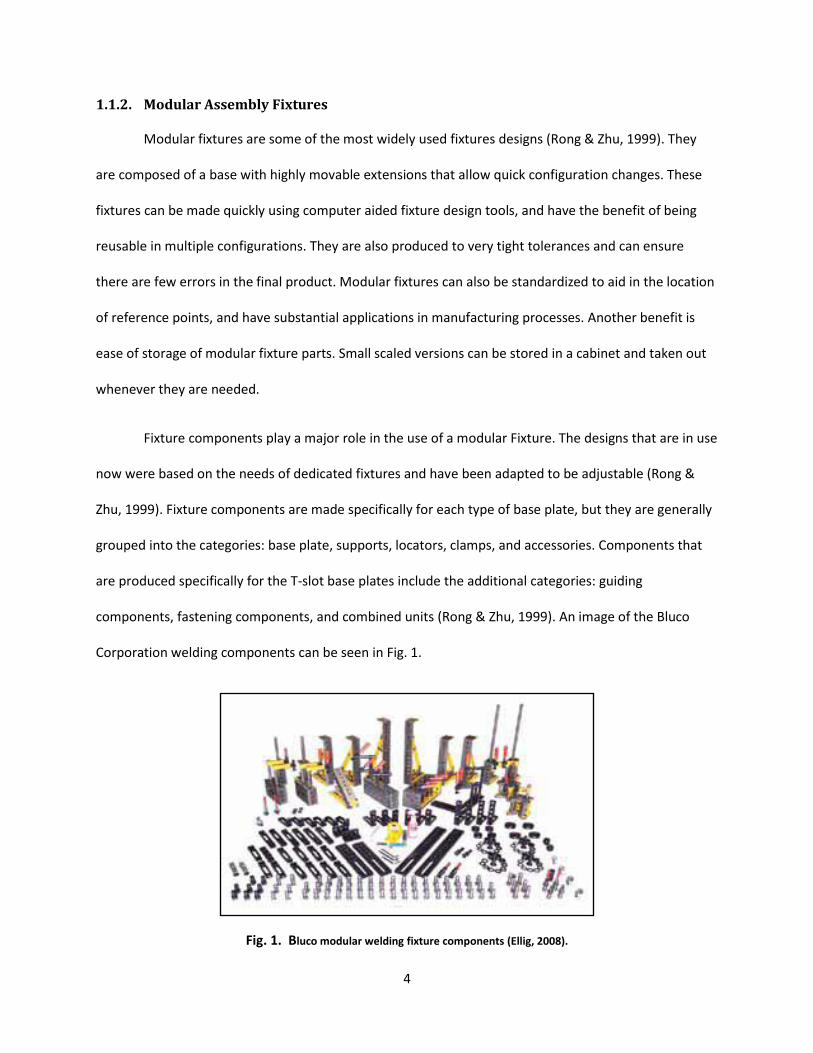
Fixture components play a major role in the use of a modular Fixture. The designs that are in use
now were based on the needs of dedicated fixtures and have been adapted to be adjustable (Rong &
Zhu, 1999). Fixture components are made specifically for each type of base plate, but they are generally
grouped into the categories: base plate, supports, locators, clamps, and accessories. Components that
are produced specifically for the T-slot base plates include the additional categories: guiding
components, fastening components, and combined units (Rong & Zhu, 1999). An image of the Bluco
Corporation welding components can be seen in Fig. 1.
Fig. 1. Bluco modular welding fixture components (Ellig, 2008).

5
Modular assembly fixtures have different requirements than the standard modular machining
fixtures. The fixtures are used specifically to hold multiple parts together so that a joining operation can
occur. This requirement is different than machining fixtures since the focus is on resisting the high forces
and providing adequate paths for coolant and chips. Welding fixtures focus on providing some rigidity
while allowing high loading/unloading cycles. These fixtures must be able to conduct and ground
electrical charges in some cases, and resist high heat and sputter. Also, welding fixtures usually have less
accuracy requirements than machining fixtures.
While modular assembly fixtures and modular machining fixtures do have different
requirements, the method of designing them is relatively standard. The art of designing fixtures requires
extensive previous experience and trial and error. This has caused much interest and research in
methods to streamline the process and to explain the steps involved.
1.1.3. Fixture Design
Fixture design can be divided into four separate steps, setup planning, fixture planning, fixture
unit design, and verification (Rong & Zhu, 1999). A chart of these steps in more detail is shown below in
Fig. 2. Before fixture design can be started there are a few preliminary steps. The first is to analyze the
workpiece to determine the part design information. This is an analysis of the part to identify the part
features and the importance of each feature. This helps in the creation of setups and the order for
fabrication. The second step is to create a manufacturing plan. This is more specific information on the
tools, speeds and feeds, and the forces exerted on the workpiece. After all these steps are completed
then the design of a fixture can be commenced. While some of the previous steps could be considered
setup planning, this stage also includes the designation of primary datum and locating features.

6
Determine locating positions
Determine clamping surfaces
Determine clamping positions
Generate baseplate design
Generate locating unit designs
Generate clamping unit designs
Perform location accuracy verification
Perform stiffness verification
Perform cost, weight, etc, verification
Setup planning:
Fixture planning:
Unit design:
Finished setup plan
Fixture design
Materials listing
Verification:
Workpiece CAD model
Machining information
Design requirements
Determine number of setups
Determine the workpiece orientation and position
Determine machining datum features and locating surfaces
Fig. 2. Fixture Design Process (Wang & Rong, 2008).
The next step is fixture planning. This includes the identification of the locating positions, the
clamping surfaces and positions. The Six-Point locating principle is the generally accepted locating
scheme. It is based on an analysis of the kinematics principle that states that six different points must be
in contact with a part in order for it to be fully constrained. Locating is generally split into two methods.
The first is the 3-2-1 principle which states that three points must be in contact with the primary datum,
two in contact with the secondary, and one contacting the tertiary. This method is used mainly for
rectangular shaped parts and is the more used of the two methods. An image of this method is shown in
Fig. 3. The second method is the 4-2-1 principle where four points are in contact with the primary datum,
two in contact with the secondary, and one in contact with the tertiary. This method is most suitable for
cylindrical objects, since more stability is required (Rong & Zhu, 1999).

7
Fig. 3. 3-2-1 Locating Scheme example. (Carr Lane Manufacturing Co., 2008).
Clamps are used to keep the workpiece securely in contact with the locators during the
fabrication operation. Clamp planning is usually done following locator planning since clamps are usually
placed in direct opposition to the locators and must not share a plane. The clamping force must be
monitored to avoid damaging the workpiece during the fabrication process.
The third step is fixture unit design. In this step the baseplate, clamps, and locators are created.
Each of these items must be chosen based off of the information determined in previous steps. The
baseplate must be versatile enough for the types of clamps and units that are being used. The locators
must restrict the degrees of freedom while not interfering with the cutting or assembly tools. Finally, the
clamps must not exert too much force on the workpiece but must securely hold the workpiece in place.
The final step is verification. In this step the fixture design is tested to ensure that it fulfils all the
requirements of a fixture. These tests include but are not limited to location accuracy verification,
stiffness analysis, and cost analysis.
These steps can often be costly, tedious, and time-consuming. Computer based technology has
been introduced to help reduce time and streamline the design process. Utilizing computer aided design
(CAD) packages for visualization aspects, users are able to create and modify fixtures completely in a
virtual atmosphere.

8
1.2. Current Research and Trends
Computer aided fixture design has been a major focus of research in the recent years. More
specifically interest has been shown in the area of integrating fixture design with CAD packages. Some
authors focus on single aspects of the fixture design process such as verification such as Kang and Rong
(2001). Other authors, Chen et al. (2007), focus on designing a user-friendly interface to combine all the
aspects of fixture design into CAD packages.
Another area of interest is intelligent methods for aiding fixture design. These are methods that
help designers create fixtures by either optimizing fixture positions, Lazaro and King (1992), or retrieving
past information to aid in the development of new solutions, Boyle et al. (2006). These proposed
methods have used many different artificial intelligence techniques to accomplish these goals. The
popular methods are, case based reasoning, expert systems, rule based reasoning, and genetic
algorithms.
While there are many authors who discuss these intelligent methods, very few go into explicit
detail about the indexing and representation of complex parts. There are even less who apply these
concepts to welding fixtures. These fixtures are more complicated due to the number of parts involved
and the intricate fixturing systems. These items will be discussed more in the literature review section,
and will be the focus of this thesis.
1.3. Thesis Objective
The objective of this thesis is to:
1. Identify and apply an indexing/representation scheme to welding fixtures
2. Propose a searching method to identify and retrieve the most suitable cases from the
case database

9
3. Provide an interface in which the CBR process can take place.
1.4. Thesis Contents
This thesis is separated into six sections. Following the introduction, Section 2 focuses on an
explanation of the research that is currently completed in the fields of computer aided fixture design
and case based reasoning. This review is subsequently analyzed to show which areas need more
explanation, and then the problem will be summarized and addressed. Section 3 focuses on proposing a
methodology to solve the objectives of this thesis. Section 4 further defines the methodology by going
into more detail. Section 5 is an application of the methodology to a case study. Finally, Section 6
discusses the results of the methodology and case studies and provides recommendations for future
work.

10
2. Literature Review
Significant progress has been made in the past years in fixture design. Research has been
conducted with regards to each aspect of the design phases, and has also lead to the use of computer
aided design (CAD) packages in order to increase efficiency. Currently there has been an increase in the
production of fixture design specific programs. Within these programs, generally known as computer
aided fixture design (CAFD) packages, efforts have been made to help reduce the amount of initial
knowledge required for effective use. The efforts include introducing artificial intelligence, by the use of
expert systems, algorithms and case based reasoning. Each method has its benefits and limitations.
Within this section an overview of computer aided design will be presented, followed by details on
the current research trends with a focus on intelligent methods, and finally the limitations of the
research will be presented to clarify the importance of the research presented in this thesis.
2.1. Computer Aided Fixture Design
Computer aided fixture design (CAFD) is the use of computers to help aid in the design of
fixtures. These computer based programs help facilitate the designer in steps that were previously very
complex. CAFD programs take the creation of fixtures in CAD packages further by not only allowing the
building of fixtures but also have assistive properties to help expedite design. These programs contain
information on tolerances, forces, and even materials, in order to assist in the production. The additions
of 3D modeling and simulation features have improved fixture design and implementation immensely.
This is especially important in the development of modular fixtures. These fixtures are generally used
multiple times for numerous situations. The ability to simulate production and analyze the forces in
multiple configurations eliminates the need for multiple prototypes and saves money as well as time.
Some areas of CAFD are still in development. Integration of CAFD with Computer Aided
Manufacturing (CAM) systems is being researched. When CAFD is integrated with CAM systems a

11
designer will be able to virtually create a workpiece, create fixtures, mount fixtures in desired locations,
test tool paths, and run simulations from start to finish. This will allow a designer to go through all the
steps for manufacturing without testing on a prototype. This will help reduce costs and prevent many
potential mistakes.
CAD/CAM integration by way of Computer Aided Process Planning (CAPP) is studied in the work
of Yuru and Gaoliang (2005). In this article an integrated system is proposed that is composed of two
modules that handle different aspects of setup planning and fixture design. The articles goal is to add
fixture design to process planning so that there can be an easy transition by using CAPP.
This type of research is not the only category of research being pursued in CAFD. There has been
substantial research in the areas of optimizing fixture locations and verification of fixtures and fixture
solutions.
2.1.1. Optimizing fixture locations
CAFD packages allow the visualization of fixture locations due to the integration in CAD
packages, but little information is provided that allows a less experienced engineer to determine the
best locating and clamping methods. Researchers are working on methods to help aid in optimization.
The determination of optimal fixture and clamping locations has been a topic of interested for
many years. One of the most popular methods of optimization is the genetic algorithm (GA) approach. A
genetic algorithm is a search algorithm that mimics evolution by employing evolutionary theory. By
using concepts such as crossover, mutation, reproduction, the algorithm provides the optimal solution.
Each of the genetic algorithm research papers contains the same general approach with slight variations
amongst the papers. The general steps are to determine the machining forces, analyze the deformation
from the forces, and then use genetic algorithms to determine the optimal positions to reduce
deformation.

12
Kaya (2005) developed a GA system that uses a chromosome library to reduce the number of
function evaluations by 93%. Krishnakumar and Melkote (2000) compared and contrasted two methods
of GA in order to indentify which method produces the best result. The technique that provided the best
results was the second method that performed fixture layout optimization in a single step. Krishnakumar
et al. (2002) provide another method of GA layout optimization by varying the fixture layout and
clamping force. Aoyama et al. apply GA in order to identify the optimal clamping for an elastic workpiece.
Genetic algorithms are not the only method studied. Wallack (1996) applies a complete
enumeration algorithm approach to optimization and focuses his research to modular turning fixtures.
2.1.2. Verification
Another area of research that is prevalent is that of verification. Verification is an important step
in the fixture design process since it is important in the determination of the fitness of the proposed
solution. Verification processes test the tolerances, stability of the fixture, and fixture constraining
ability, etc.
Kang and Rong (2001) propose a fixture design verification Computer aided fixture design
verification (CAFDV) which focuses on analyzing geometric constraint, tolerances, stability, stiffness and
accessibility, etc. This initial model is further detailed in a three part publication in 2003. The CAFDV
system is shown in Fig. 4.

13
Fig. 4. Computer Aided Fixture Design Verification system (Kang & Rong, 2001).
Zheng et al. (2008) propose a stiffness model of a fixture unit. This model is proposed with a
method of recognizing contact stiffness parameters. Hurtado and Melkote (2001) also propose a
stiffness model for fixtures. The difference is that they optimize the models based on of the tolerance
limits. This optimization can create the most feasible dimensions for the fixtures but is based on the
assumption that the workpiece is a rigid body.
There are many papers that use a Finite Element Method to predict workpiece deformation and
use that as a method of verifying if the fixture is good depending on how much deformation is reduced
on the workpiece. Amaral et al. (2005) Satyanarayana and Melkote (2004) use finite element method to
determine the effect of elastic deformation and forces on the stability of a workpiece. Siebenaler
analyzed the deformation that occurs when contact friction, mesh density and other factors are varied
within the workpiece-fixture unit system. Melkote (2006), Ratchev et al. (2007), and Asante (2008) also
propose deformation analysis using FEM.
There are limitations to the CAFD research presented in the above sections. While there are
some methods that employ intelligent systems to help aid the program user there are still very few

14
methods that provide more than just basic assistance in optimizing or verifying fixture information.
Those items are on the design end of the spectrum. The above research does not provide information
on past results and does not automatically modify or provide aid in the modification of designs.
Currently CAFD programs are not able to retain and restore previous designs to suggest new
ones based on the previous designs. The designer must remember or review the previous designs in
order to identify key lessons to apply to the current problem. CAFD programs are not able to learn from
the previous examples to better aid designers. Additionally, these programs are not able to, beyond
limited verification functions, judge the quality of a design. There has been development on different
systems that are able to provide this level of system intelligence.
2.2. Intelligent Methods
Intelligent methods also known as artificial intelligence methods simulate the processes that a
human undergoes when reasoning through a problem. Case based reasoning and expert methods are
the most common methods researched. This section will concentrate on case based reasoning.
2.2.1. Case based Reasoning
Case based reasoning (CBR) describes a method that uses previous cases to explain and create
solutions to new problems. CBR can be considered reasoning by analogy. Using similar past
circumstances to understand and adapt to new issues. There are two major branches of CBR,
interpretive and problem solving. A lawyer uses interpretive CBR in daily practice to alleviate or affirm
convictions. A lawyer uses previous cases as example of previous decisions in a court room and tries to
connect the current case with the previous ones to prove that the same verdict should be made.
Problem solving CBR is using a previous method to help determine solutions to new problems. This is
done by drawing similarities between the two cases and analyzing specific actions that lead to a
beneficial outcome.

15
Both methods are fundamentally similar in how they are executed. Fig. 5 shows the connection
between the two types of CBR. Both methods begin with the retrieval stage, which bring forth the
appropriate memory or case for analysis. Based on these memories a general solution is proposed. This
is when the two CBR systems split. Interpretive CBR attempts to justify the actions based on the
previous memories while problem solving attempts to adapt the previous solutions to match the current
issue. Both CBR methods then criticize the proposed adapted or justified solution and evaluate it. If the
evaluation is not suitable then the process is returned to the adapt/justify stage. If the outcome is
suitable then the case is then stored for future use.
Fig. 5. Flow chart of interpretive and problem solving CBR. (Leake, 1996).
Problem solving CBR can be further broken down in the four stages, index, retrieve, adapt, and
revise. Indexing is the identifying and representation of key feature within a case for storage. These
features can be information such as geometry, manufacturing information, fixture design information,
etc. This information is then stored in a database for retrieval. Retrieval is the method of searching the
database to find similarities between the cases based on the indexed information. Adaptation is the
changing of the retrieved information to best fit the new problem. The final step is revision which is the

16
verifying of the fitness of the proposed solution and determining if the process needs to be started over
again.
There are many benefits to this system. A major benefit is that specific aspects of a case can be
used to help determine solutions rather than having to use it in its entirety. Learning can be achieved
regardless of success or failure since both failed and successful cases are stored in the database. The
knowledge in the database is solely based on the number and quality of the cases. Cases can be added
and removed easily from the database. CBR allows a user to learn from previous mistakes by keeping
them stored and easily available. Users will also be more accepting of solutions proposed by CBR
systems because the proof is completely visible in the previous case.
The rest of this section will focus the research on problem solving CBR and include information
on the case library (database and indexing), similarity analysis (recalling) and Case modification
(adaptation).
2.2.2. Current Research on Case Based Reasoning
The case library is the database where the cases are stored for retrieval. There has been little
research dedicated to the case library most of the information found was contained in articles that
either were creating a full framework for fixture design or those specific to indexing/retrieval schemes.
Boyle, Rong, and Brown (2006) propose a two case library. Subramaniam et al. (2001) propose a
full CBR system that uses a genetic algorithm for searching the indexed database. From the search
results the system identifies the best result and rates the choices in order for the designer to select
which features they would like to reproduce.
Indexing is the method of classifying information so that it can be easily searched and retrieve
within the case library. Indexing must adequately represent the information contained within a case and

17
must be easy to use and search for retrieval processes. Fan and Kumar (2005) provide an indexing
scheme using XML formatting. In this paper XML is used because of its versatility. It is a language that is
able to be sent over the internet easily and is very popular when creating online web applications.
The search process can be difficult to conceptualize. Many papers use similarity equations to
find similar entries in a case library. Mervyn et al. (2005) chose another approach. They use an
evolutionary search algorithm in order to produce solutions base on similar functions found in genetic
algorithm research. This method provides a thorough search for large databases, but is not needed for a
small database such as the one being developed.
The final step in case based reasoning is the adaptation of the case to suit the new design. Aarno
et al. (2005) also uses an evolutionary search algorithm to search and adapt fixtures.
2.3. Summary of Problem and Current research
While there have been efforts to automate fixture design by using intelligent methods there are
still some areas that could use more development. Case based reasoning research has attempted to add
a reasoning method to fixture design and research conducted on CBR has made great strides. There still
is more to be done. While it is important to propose general methodologies it is also important to well
define proposed methodologies to help aid the development of the research into commercial products.
Case based reasoning also has some problem areas. One of the major problems is that CBR requires
a large number of high quality cases to be effective. These cases can be either good or bad cases, but
the system still requires a large number of them in order to be the most robust system. In regards to
indexing and recalling, determining an indexing scheme and identifying which items should carry more
weight when being retrieved are some issues. Adaptation can also be problematic. Identifying what to
adapt is an area that causes problems, and in fully automated systems there is the issue of determining
what can be adapted and controlling the adaptation process.

18
The paper written by Wang and Rong (2008) is the basis of this thesis. The approach that is defined
in the paper is expanded and more information is added to provide more detail on how to implement
this system. The system explain in the paper defines an indexing and retrieval system that solves the
issues related above. For indexing the system defines a retrieval system that incorporates human
interaction to retrieve the most suitable examples. It uses the human interaction to identify what needs
to be adapted, determine what can be adapted, and to control the adaptation process. This thesis will
strive to go beyond the overarching explanation, and try to specify and1 improve the approach
presented in the works of the authors. Additionally, this thesis will present an indexing scheme that will
help in the retrieval process. The proposed methodology is presented in the next section.

19
3. Proposed Methodology
The case based reasoning system proposed in this paper will focus on the specific aspects of
indexing, representation and searching the database for case information and will not focus very much
on the final step of CBR, automated adaptation. The concept behind this system is that in order for case
based reasoning to reach its full potential the system requires an all encompassing system to adequately
define the cases within the database. The proposed system will mimic the design steps of an
experienced designer while integrating information garnered from the CAD package to create a
complete assembly case. A model of the methodology can be found in Fig. 6.
The model is best read from the top down. This structure shows how the user will interact with the
user interface in order to retrieve the most relevant solutions. The first step is for the user to enter the
workpiece and manufacturing requirements. This information is entered in boxes that are easily to
understand and simple to use. The next step is to enter the workpiece and fixture design requirements.
This step is used to aid in the searching process. The CBR system uses this information to retrieve the
best solution while incorporating the user feedback during the process. Once this step is complete a
final solution is reached and the quality of the solution is then verified.

20
Fig. 6. A general idea of the proposed methodology.
The proposed method is further split into three main items that work together to produce the CBR
system. The three items are the representation of the information and the knowledge, an
XML/Database, and an application platform. The information and knowledge representation is the
method of decomposing the information into its component parts. This is generally known as an
indexing scheme. These representation methods are stored in the XML databases in an easily searchable
fashion. The XML database is made up of another three parts. The first part is the design solutions
library, which catalogues all the information pertaining to the entire design (workpiece and fixturing
information). The second part is the fixture library. This library contains the information on the specific
fixturing units (name, type, size, etc…). The third part is the domain knowledge base. This is the
company specific information on general design rules, common practice, and principles of fixture design.

21
The final section of the methodology is the application platform. This is where the user interfaces with
the system and can direct the retrieval system to gather specific results.
The CBR system is not a completely automated one. It is made in a manner that allows constant
feedback from the designer and directly uses that feedback to produce increasingly more specific results.
The first and most important part of the system is the indexing. The method of defining the case allows
the system to retrieve the most applicable solution from the case library. The case library is the location
where all of the cases will be stored for retrieval. Each case is indexed within the case library in XML.
The indexing method that will be used in this system is a mixture of attribute-value pairs with some
elements of text organized into a hierarchical structure. This system employs a mixture of indexing
schemes in order to encompass the full designer’s intent as well as the designer’s outcome. The
attribute-value pairs will be weighted by importance and provide the feature related information. The
text will provide the designers intent which is hard to communicate with the attribute-value pairs. The
hierarchical structure is to preserve the relationships between the assemblies, its component parts, and
fixturing units.
Case retrieval will be conducted in a multi-stage approach which is used to maximize the efficiency
of the search algorithm. The stages in the case retrieval multi-stage approach can be seen in Fig. 7. The
first step is for the designer to input the workpiece and design requirements into the interface. The first
stage of the scan is a surface level search. This search will focus on the input material (workpiece and
design requirements) and by similarity analysis the most similar cases will be found. Following this the
designer chooses from the cases which one is similar to the new case that is input. After looking at the
information in this case and the other similar ones retrieved the designer begins to create a conceptual
fixturing plan for the workpiece. This fixturing plan outlines where the designer intends to put the
clamps and locators but does not specifically outline which units are used to fulfill those functions.

22
Based off of this information the second stage of the scan will scan deeper into the library to find cases
with similar fixturing parameters. Once all of the solutions are recovered the designer looks through the
cases and determines which design is the most relevant case. If the chosen case has the fixturing
scheme that the designer desires down to the fixturing unit choices the designer can then choose to go
to the verification stage. If the case is not satisfactory then the third search stage will help narrow down
more choices.
1st indexing
Input new design
information – workpiece
and design requirements
Provide solutions
1st level search - Retrieve
past solutions
Designer produces
tentative fixturing plan
Designer selects most
similar solution
2nd
level search – Retrieve
based off of fixturing plan
Workpiece Level
3rd
level search – Retrieve
best fitting units
Fixture Setup
Level
Fixture Unit
Design Level
If each unit in fixturing
solution is acceptable
If any unit in fixturing
solution is unacceptable
Verify unit design
Modify fixturing design
If doesn’t qualify
Verify Solution
Complete fixture solution
If qualifies
Fig. 7. – Case Retrieval Flowchart.

23
The third search stage is specific to the fixture unit level. This level searches through the database
to find which fixturing unit is the best for the situation. The search provides all the solutions that would
best fit with the workpiece and then the designer can choose to accept the unit or go back to any
previous step and revise the solution. Within this stage the designer can verify the fixture units by
various functions such as an interference check, placement checks, and simulation modeling. Once the
designer is finished and content with the finished design the final fixture is then subject to more testing
to ensure that the solution is robust.
The benefits to this system are that if only one search was conducted many relevant case options
might be neglected. Having a multi-tiered system will iteratively narrow down the selections until the
most suitable cases are determined. The human computer interface to help reduce the solutions with
the help of visual aids is also another benefit. The next section will discuss the methodology in more
detail.

24
4. Case Representation and Retrieval
This section details the proposed system for indexing, representation, and retrieval of a design case.
The first section will cover the indexing and representation, while the second section will discuss the
retrieval method. The third section is about the interface that has been created for this CBR system.
4.1. Fixture Design Case Information Modeling
Case indexing as defined in previous section is the decomposition of a case into its relevant parts.
Indexing is the cataloging of every conceivable observation on an item and then storing them in a table.
Case indexing in order to be effective must be as comprehensive as possible. The previous research
focuses mainly on machining features. This paper will discuss a template for decomposing complex
assembly parts. The general flow of the Information modeling and representation is shown in Fig. 8.
Technical information/data in Fixture design
XML standard Database
Fixture Design Case representation method Fixture components representation method
Design solution library Domain knowledge
baseFixtures unit library
Fig. 8. Information modeling and representation flow chart.

25
The modeling begins with the technical information for the fixture design. The specifics will be
detailed in the following sections. This information is then represented in a hierarchical structure using
the XML standard. This information is then further split into the design solutions library, the domain
knowledge base, and the fixture unit library. This separate information is stored in a general database
which can be easily updated or added to.
The following sections will focus on the specific information that is contained in the database and
include information about the representation method eXtensible Markup Language (XML).
4.1.1. Conceptual Design
The conceptual design is the first step in indexing. The conceptual design is comprised of the initial
requirements given to the designer in order to begin formulating a design. The most common
information provided is the intended function. This is one of the single most important pieces of
information in conceptual design. Drawn from the function are the specifics of potential shape, material
requirements, fabrication methods, and others. Additional information that might be provided to a
designer is the interaction information, tolerances, environmental requirements, and relative
dimensions. Using this information a conceptual design is created.
Important to the conceptual design specifically for assemblies is the function of the part and its
correlation to the function of the whole. In an assembly a part is no longer a standalone object, it must
fulfill its individual role as well as its role as part of the assembly. The information on how the assemblies
are connected physically is important as well. Indexing of this information is very important since it
contains information that cannot be directly taken from the final workpiece part. Within this proposed
system text will be used to describe most of the conceptual information.
Within the interface the text can be directly viewed and searched. It is separated into sections so
that the designer can define the initial concept that was provided. The separation into sections also

26
allows for searching of a specific topic. For example if a designer is interested in functional properties of
a workpiece and wanted to understand the specific reasoning for why component was used that way a
search of the text will provide an answer. This text information is considered to be an abstract
explaining in 350 words or less what the functional specifications, the reasoning behind fixturing the unit
a certain way and possible improvements to the fixture design. Similar to an abstract for an article in a
journal, the designer who is inputting the information into the interface will add keywords in a separate
section so retrieval can be expedited.
4.1.2. Workpiece-fixture system
The next step is to capture the workpiece-fixture system. The workpiece-fixture system is an idea
group that contains all the knowledge of the workpiece, setup, and fixturing units. The top four levels of
this scheme can be seen in Fig. 9.

27
Fig. 9. Indexing Decomposition Structure.
4.1.2.1. Workpiece
The first subsection of the design case is workpiece. This subsection details all of the information
about the workpiece. The first item is the name of the workpiece or the family name of the workpiece.
This is to identify the workpiece and help group it into a similar family of parts for easy retrieval. This
subsection is further decomposed into workpiece specific information such as the type. The different
types that are usually welded are pipe, sheet metal, bulk (large parts), mixed (such as automobile which
Design Case
Conceptual Design
Workpiece-fixture
Relationship
Workpeice Name/Family
Type
Pipe
Sheet
Bulk
Mixed
Assembly information
Part information
Number of parts
Type of assembly operation
Geometric Information
Size
Weight
Shape
Fixturing Setup Plan
Locating Scheme
Locating datums and surfaces
Clamping surfaces
Unit Configuration
Set of Points (supergraph)
Fixturing Structure Unit
Single Fuction
Multiple Function
Locator/Clamping pairs
28
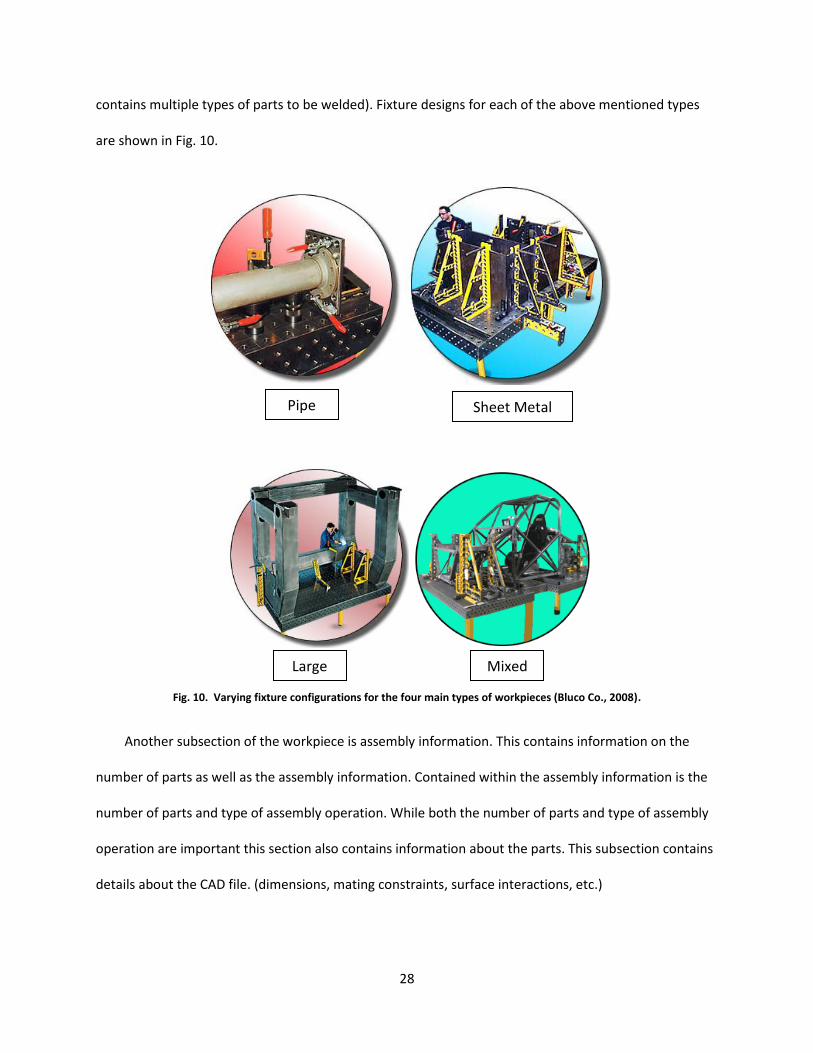
contains multiple types of parts to be welded). Fixture designs for each of the above mentioned types
are shown in Fig. 10.
Fig. 10. Varying fixture configurations for the four main types of workpieces (Bluco Co., 2008).
Another subsection of the workpiece is assembly information. This contains information on the
number of parts as well as the assembly information. Contained within the assembly information is the
number of parts and type of assembly operation. While both the number of parts and type of assembly
operation are important this section also contains information about the parts. This subsection contains
details about the CAD file. (dimensions, mating constraints, surface interactions, etc.)
Pipe Sheet Metal
Mixed Large

29
The last subsection under workpiece is the geometric information. This contains the size
(dimensions), overall weight, and the shape of the part. This subsection pertains to just the overall
assembly, not its component parts.
4.1.2.2. Fixturing setup plan
The second subsection under the design case is the fixturing setup plan. This information focuses
on the interaction between the locators and the workpiece. Under the fixture setup plan is the locating
scheme. This details the locating and clamping datum and surfaces. The unit configuration is also
considered and the set of points assembled into a supergraph is defined. A supergraph is a
representation of the surfaces and boundaries of the workpiece as a set of points. A supergraph also
contains all the information regarding the points that are chosen to be fixturing points, either a clamping
point or a locating point. A supergraph represents each of these points in a hierarchical structure. An
example of a supergraph is shown in Fig. 11.
Function: side locating
Position: -465.0000, -308.2466, 189.5216
Direction: 1.0000 -0.0000 -0.0000
FaceF: Name[SideLocatingPoint0_onFace]
Feature_ ID[501]
World coordinate system
Fixture solution
Workpiece geometric features
Locating
Fixturing plan
Locating P0
Locating P1
… ...
Clamping
Function: side clamping
Position: 465.0000 -327.7889 192.2557
Direction: -1.0000 -0.0000 -0.0000
FaceF: Name[SideClampingPoint0_onFace]
Feature_ ID[505]
Clamping P0
Clamping P1
… ...
Fig. 11. Example of a Supergraph (Wang & Rong, 2008).
30
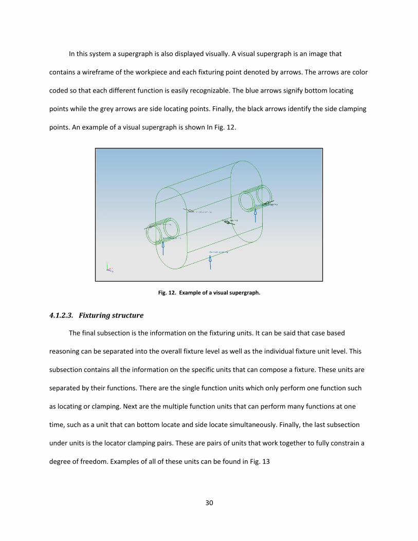
In this system a supergraph is also displayed visually. A visual supergraph is an image that
contains a wireframe of the workpiece and each fixturing point denoted by arrows. The arrows are color
coded so that each different function is easily recognizable. The blue arrows signify bottom locating
points while the grey arrows are side locating points. Finally, the black arrows identify the side clamping
points. An example of a visual supergraph is shown In Fig. 12.
Fig. 12. Example of a visual supergraph.
4.1.2.3. Fixturing structure
The final subsection is the information on the fixturing units. It can be said that case based
reasoning can be separated into the overall fixture level as well as the individual fixture unit level. This
subsection contains all the information on the specific units that can compose a fixture. These units are
separated by their functions. There are the single function units which only perform one function such
as locating or clamping. Next are the multiple function units that can perform many functions at one
time, such as a unit that can bottom locate and side locate simultaneously. Finally, the last subsection
under units is the locator clamping pairs. These are pairs of units that work together to fully constrain a
degree of freedom. Examples of all of these units can be found in Fig. 13

31
Fig. 13. Single Function, Multiple Function, and Locator/Clamp Fixture Units respectively (Caterpillar, Inc.).
4.1.3. XML representation
Internet and internet based information systems has become a more prevalent foundation for
informational storage. Because of this, information needs to be able to be sent over the internet, while
maintaining its structure. XML (eXtensible Markup Language) has the benefits of being neutral,
platform-independent, and flexible, and allows structured data in web applications (Fan & Kumar, 2005).
Using XML to represent the indexed data will allow flexibility in the database. Since XML is very
compatible with web browsers information on cases can be sent over the internet quickly and
effectively. The possibility of moving CBR systems to completely web based applications is also a
possibility. Using XML a hierarchy can be easily defined by creating parent children tags. These tags can
have any name but are used to establish relationships between different parameters. An example of
XML script for a side locating point is in Fig. 14.

32
Fig. 14. XML Script for Fixture Setup
The figure shows that the information is clearly separated into the parent and children format.
For example FDSetup has the children workpiece, worktable, working points, fixture solution, and
assembly simulation. This information can be opened in any web browser regardless of type and still be
kept in the same format. A full XML representation sample can be found in Appendix A. XML
representation of a sample fixturing solution
4.2. Fixture Design Case Retrieval
In the methodology a retrieval process was detailed. In this section the information regarding how
the process works will be mentioned. This section is divided into four sections. The first will go into more
detail about the similarity analysis while the second section will speak about the weighting system. The
third will detail the retrieval system, and the fourth will show the interface and how the user interacts
with it.

33
4.2.1. Similarity Analysis
In this method all of the retrieval is done using a closest neighbor matching scheme. In this scheme
the closest match is found by a similarity analysis method. In this case the method that was chosen is to
use the cosine formula to find the closest neighbor of feature vectors. A feature vector is technique to
represent parts information in a mathematical way. In this case the major information that is turned into
feature vectors are the workpiece information, supergraph of workpiece, and the fixture units.
Wang and Rong (2008) best describe the feature vectors for each step. The workpiece feature
vector is defined as },,{ MPFXworkpiece where F is the functional features which can be separated
into part family, material conditions, and others. P is the physical parameters such as size, shape and
boundary features. Finally, M is the manufacturing information like process the workpiece undergoes
and quantity. The supergraph information is denoted by },...,,{ 21 NWG PPPSX . Sw is the shape features
of the workpiece in the world coordinate system. P is the },,,{ FFaceDirectionPositionFunctionP of
each supergraph point. Finally, the fixture unit vector is },,{ BFSXunit where S is the structural features,
F is the functional factors, and B is the behavioral type.
Retrieval of the indexed case is done by similarity measurement. The similarity measurement is
conducted using the cosine formula. This equation, YX
YXYX
),cos( , calculates the cosine between
two vectors. Similarity is measured by which results are closest or equal to 1. The closer to 1 the more
similar the vectors are.
4.2.2. Weighting
The three stage search concept that is presented in this thesis provides for a comprehensive
search of cases stored in the case library. By using the similarity analysis of feature vectors acquisition of
matching data is very easy to obtain. An important aspect of each stage is specifying searches. In order
34
to ensure that the most relevant information is retrieved weight is added to each feature to denote
which items are more important to each search stage.
The weights to each item are passively added to the system as well as actively. Passively the
hierarchical structure allows the broadest categories to be searched first, and then the search will focus
on the less broad. This is helpful for the first round of searching where the majority of the information is
within the first few levels. The active weighing helps define what is searched first. Active weighing is
when a weighting vector is used to influence the outcome of the vector system. Assuming that a vector x
is written in this form ],...,[ 10 nxxxX and the weighting vector is denoted as ],...,[ 21 nwwwW
then feature vector defined after the weighting is i
ii xwx . The active weighing will be specifically
for items such as type, family name, shape, and number of parts.
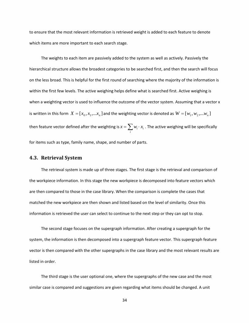
4.3. Retrieval System
The retrieval system is made up of three stages. The first stage is the retrieval and comparison of
the workpiece information. In this stage the new workpiece is decomposed into feature vectors which
are then compared to those in the case library. When the comparison is complete the cases that
matched the new workpiece are then shown and listed based on the level of similarity. Once this
information is retrieved the user can select to continue to the next step or they can opt to stop.
The second stage focuses on the supergraph information. After creating a supergraph for the
system, the information is then decomposed into a supergraph feature vector. This supergraph feature
vector is then compared with the other supergraphs in the case library and the most relevant results are
listed in order.
The third stage is the user optional one, where the supergraphs of the new case and the most
similar case is compared and suggestions are given regarding what items should be changed. A unit
35
search is then initiated and the most suitable unit is determined from the functional height of the
workpiece. The option to enter specialized custom units is also available.
Finally, the solution is verified to identify if the quality of the fixturing. This is done by interference
checks, tolerance analysis, and stability checking to ensure that the fixture is sound. Once a suitable
fixture is found it can be saved. All of this information is shown in graphical form in the next section
regarding the interface.
4.4. Interface
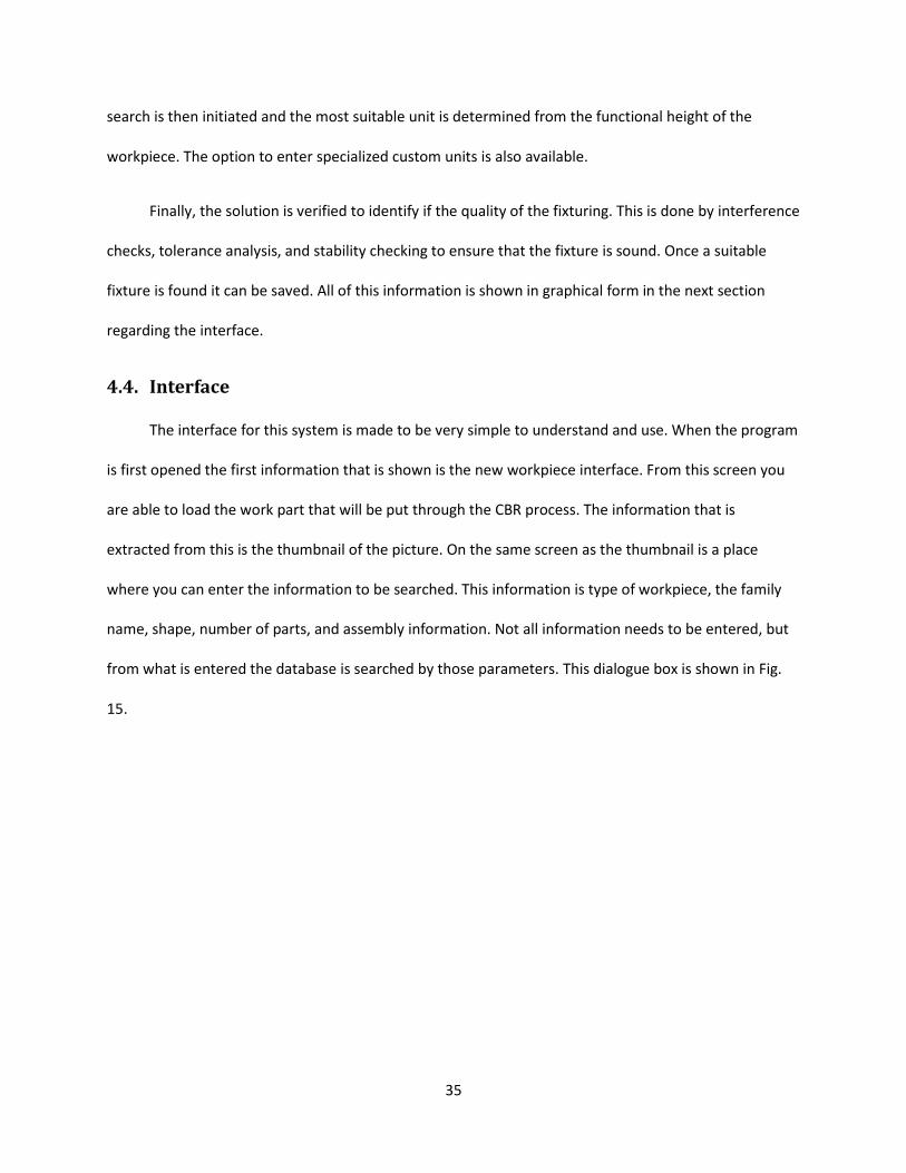
The interface for this system is made to be very simple to understand and use. When the program
is first opened the first information that is shown is the new workpiece interface. From this screen you
are able to load the work part that will be put through the CBR process. The information that is
extracted from this is the thumbnail of the picture. On the same screen as the thumbnail is a place
where you can enter the information to be searched. This information is type of workpiece, the family
name, shape, number of parts, and assembly information. Not all information needs to be entered, but
from what is entered the database is searched by those parameters. This dialogue box is shown in Fig.
15.
36
Fig. 15. Search dialogue box.
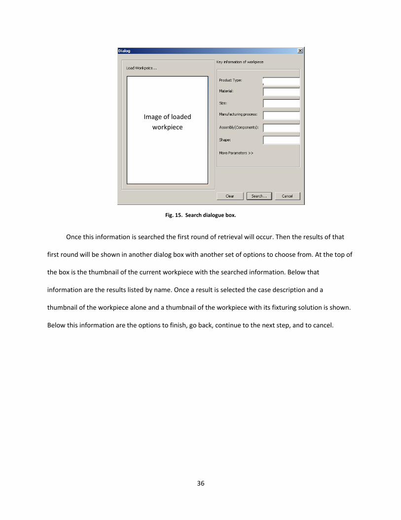
Once this information is searched the first round of retrieval will occur. Then the results of that
first round will be shown in another dialog box with another set of options to choose from. At the top of
the box is the thumbnail of the current workpiece with the searched information. Below that
information are the results listed by name. Once a result is selected the case description and a
thumbnail of the workpiece alone and a thumbnail of the workpiece with its fixturing solution is shown.
Below this information are the options to finish, go back, continue to the next step, and to cancel.
Image of loaded
workpiece

37
Fig. 16. First stage of CBR dialogue box
When the next button is chosen the program allows the user to use the CAWFD interface coupled
in UGS (Worcester Polytechnic Institute developed software) to create the fixturing plan for the
software. Once this information is finished the information is imported into the CBR process and the
next level of searching is started. This dialogue box is shown in Fig. 17.
Image of loaded workpiece
Image of selected case’s
workpiece
Image of selected case’s
fixture plan
Retrieved list of
case names

38
Fig. 17. Supergraph import dialogue
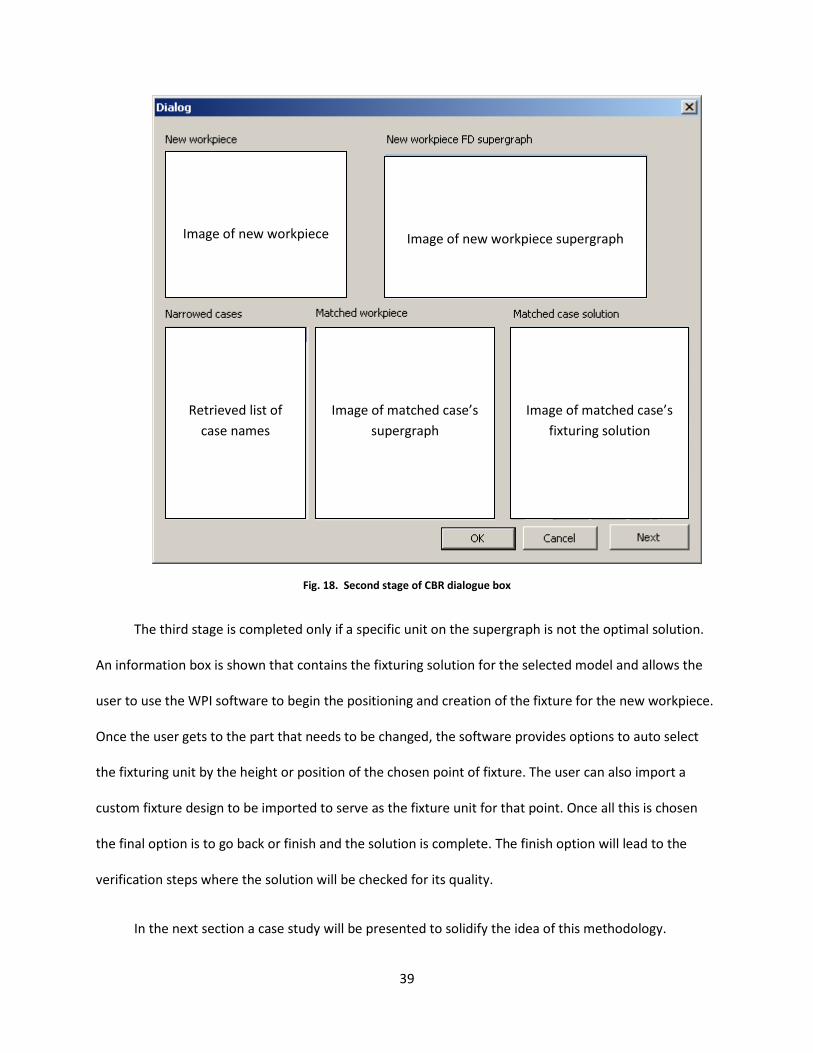
Following the second search the next interface box is shown with the results of the search. This
information box contains the image of the current workpiece. Next to this picture is the image of the
supergraph that was created in the previous step. Below this information is the list of the case result
with similar solutions. Once a case is selected the supergraph and the cad model of the fixturing solution
will be shown in the box next to it. If the user finds a solution that is acceptable a selection of the Ok
button will allow the user to finish the creation of the solution. The other options are to cancel and to go
on to the next stage of searching.
Image of selected case’s supergraph
Retrieved list of case names
39
Fig. 18. Second stage of CBR dialogue box
The third stage is completed only if a specific unit on the supergraph is not the optimal solution.
An information box is shown that contains the fixturing solution for the selected model and allows the
user to use the WPI software to begin the positioning and creation of the fixture for the new workpiece.
Once the user gets to the part that needs to be changed, the software provides options to auto select
the fixturing unit by the height or position of the chosen point of fixture. The user can also import a
custom fixture design to be imported to serve as the fixture unit for that point. Once all this is chosen
the final option is to go back or finish and the solution is complete. The finish option will lead to the
verification steps where the solution will be checked for its quality.
In the next section a case study will be presented to solidify the idea of this methodology.
Image of new workpiece
Image of new workpiece supergraph
Image of matched case’s
supergraph
Image of matched case’s
fixturing solution
Retrieved list of
case names

40
5. Case Studies
In this section the methodology detailed in the previous sections will be implemented and tested to
on an example of an automobile muffler. This chapter is divided into multiple sections. The first section
will detail the information about the case study. The second section will focus on the indexing of the
case. Finally, the third section will detail the retrieval and adaptation of the example based off of the
previous cases in the database.
5.1. Muffler Case
The system presented in the methodology section will be applied to an example workpiece, an
automobile muffler case. A muffler case is typically an assembly of four or five parts depending on the
brand or specific requirements of the muffler. The typical welding locations on a muffler case are shown
in Fig. 19. Typically a muffler case is welded around the muffler exhaust inlet/outlet (1). This weld is
repeated on either side of the case. The case itself can, depending on how it is broken into pieces, be
either welded along its cross section (2) or on the outside surface seam of the case (3). The outside seam
is also welded on both sides of the muffler case. The addition of these welds can equal anywhere from
three to five welds per muffler.
Fig. 19. Thrush welded muffler case (HSPN news, 2007).
1
3
2

41
The typical welding style for mufflers is metal inert gas welding (MIG), tungsten inert gas
welding (TIG), or laser welding. The most preferable is laser welding and when companies make muffler
cases it is usually done with robotic arm. The benefits of robotic arms are that they provide the same
welds repeatedly. They do depend heavily on workpiece placement since the arm is programmed to do
specific moves in a specific sequence and location. Fixturing for a workpiece in a robotic arm is very
important. Some robotic arms made specifically for welding mufflers include the addition of variable
fixtures to ensure the correct positioning of the muffler. In this example modular fixtures are used in
place of the specific robotic arm and fixturing systems. Examples of companies that create commercially
available robotic welding systems are Woojin Engineering (Woojin Engineering Co., Ltd., 2003) and BAE
design and development (BAE Design and Development, Inc, 2009).
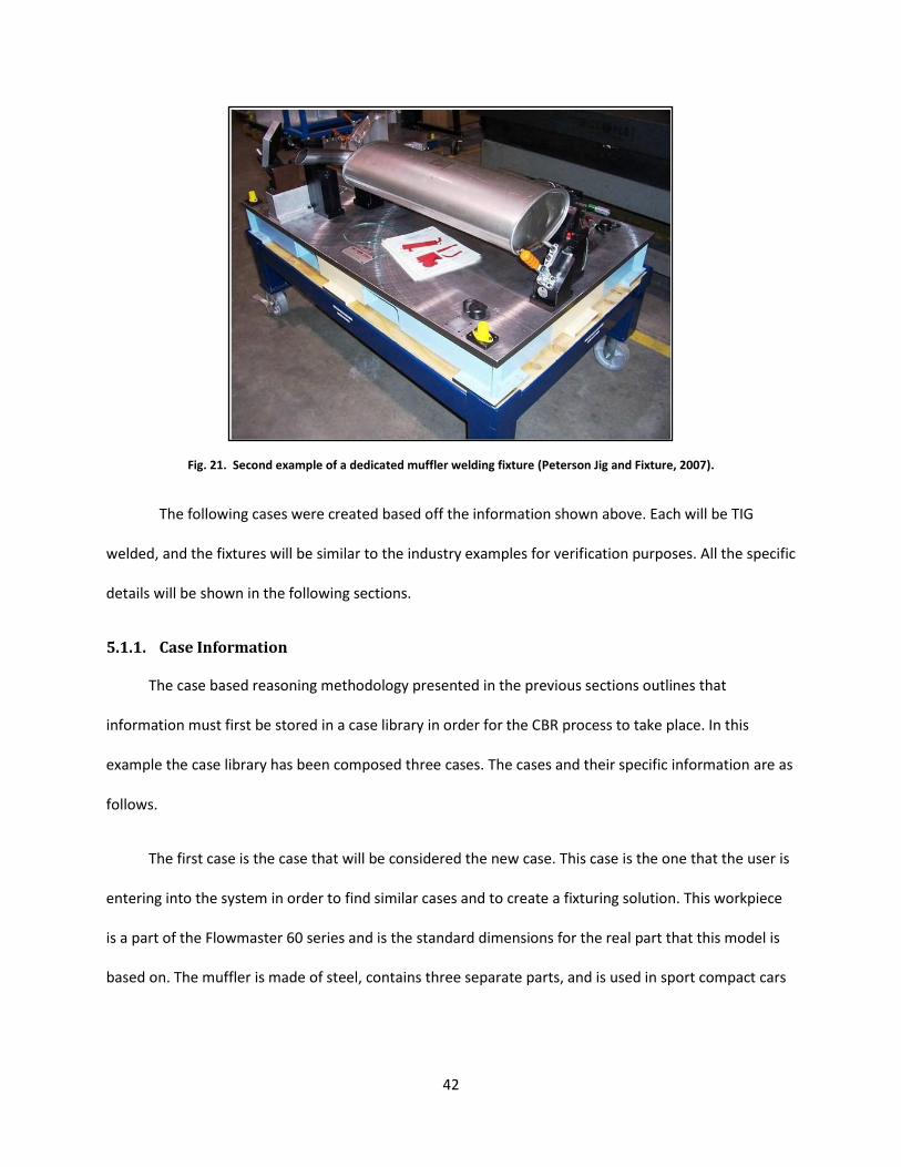
In a search for specific fixtures for muffler welding there were only a few options that were
found. There were only two dedicated fixtures and no modular fixtures examples. The two examples are
shown in Fig. 20 and Fig. 21. In order for the fixtures to be designed in the CAFD framework that has
been developed at Worcester Polytechnic Institute, these fixtures had to be reproduced in a modular
fixture format.
Fig. 20. First example of a dedicated muffler welding fixture (Peterson Jig and Fixture, 2007).
42
Fig. 21. Second example of a dedicated muffler welding fixture (Peterson Jig and Fixture, 2007).
The following cases were created based off the information shown above. Each will be TIG
welded, and the fixtures will be similar to the industry examples for verification purposes. All the specific
details will be shown in the following sections.
5.1.1. Case Information
The case based reasoning methodology presented in the previous sections outlines that
information must first be stored in a case library in order for the CBR process to take place. In this
example the case library has been composed three cases. The cases and their specific information are as
follows.
The first case is the case that will be considered the new case. This case is the one that the user is
entering into the system in order to find similar cases and to create a fixturing solution. This workpiece
is a part of the Flowmaster 60 series and is the standard dimensions for the real part that this model is
based on. The muffler is made of steel, contains three separate parts, and is used in sport compact cars
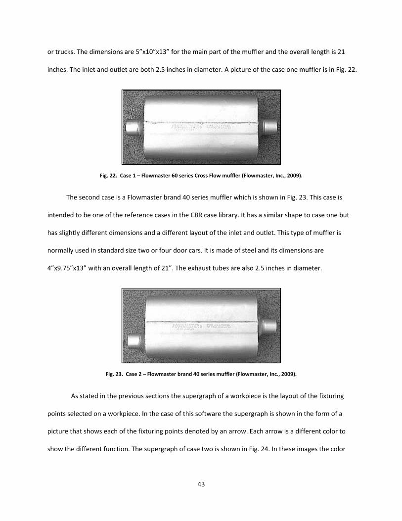
43
or trucks. The dimensions are 5”x10”x13” for the main part of the muffler and the overall length is 21
inches. The inlet and outlet are both 2.5 inches in diameter. A picture of the case one muffler is in Fig. 22.
Fig. 22. Case 1 – Flowmaster 60 series Cross Flow muffler (Flowmaster, Inc., 2009).
The second case is a Flowmaster brand 40 series muffler which is shown in Fig. 23. This case is
intended to be one of the reference cases in the CBR case library. It has a similar shape to case one but
has slightly different dimensions and a different layout of the inlet and outlet. This type of muffler is
normally used in standard size two or four door cars. It is made of steel and its dimensions are
4”x9.75”x13” with an overall length of 21”. The exhaust tubes are also 2.5 inches in diameter.
Fig. 23. Case 2 – Flowmaster brand 40 series muffler (Flowmaster, Inc., 2009).
As stated in the previous sections the supergraph of a workpiece is the layout of the fixturing
points selected on a workpiece. In the case of this software the supergraph is shown in the form of a
picture that shows each of the fixturing points denoted by an arrow. Each arrow is a different color to
show the different function. The supergraph of case two is shown in Fig. 24. In these images the color

44
blue denotes bottom locating, grey is side locating, and black is side clamping. This case is made of three
bottom locating, two side locating, and two side clamping locations.
Fig. 24. Case 2 Supergraph.
The complete fixturing solution can be seen in Fig. 25. In this case it is positioned in the upright
orientation shown in Fig. 20. Even though this fixture is not as detailed as the dedicated fixture, it will
serve the same purpose. This fixture is composed of a worktable (Bluco unit D28-01001-001B), three V
blocks used for bottom locating (D28-9004-000A), two clamps used for side locating (D28-3002-000C),
and two locators used for side locating (D28-03001-00A). There are no top clamping units because the
weight of the piece will be sufficient enough to handle the welding stresses put on the workpiece.

45
Fig. 25. Case 2 Fixturing Solution.
The third case is also used for reference in the case library. This muffler is based on the stock
Flowmaster 80 series but its dimensions are two times larger. The reason for this size increase was
because the Bluco units are made for larger scaled objects and are a minimum size of six inches tall. The
stock model is made for use in the Chevy Camero and Pontiac Firebird. This muffler is also made of steel
and its modified dimensions are 8”x19.5”x30” with a 38” overall length. The diameters of the inlet and
outlet pipes are five inches.
Fig. 26. Case 3 Flowmaster 80 series Cross Flow muffler (Flowmaster, Inc., 2009).

46
The supergraph of this case is shown in Fig. 27. The supergraph for this case is more complex.
The workpiece is intended to be horizontal and is similar to the second dedicated fixture shown in Fig.
21. The supergraph is composed of five bottom locating, two side locating, and two side clamping units.
Once again there are no top clamping units due to the weight of the workpiece.
Fig. 27. Supergraph of Case 3.
The fixturing solution is different than the previous case. Since the size was increased double of
the stock value the system was able to choose more fixtures that are better suited for specific positions.
There are a few fixture units that are made up of two components. The table is a Bluco standard D28-
01004-001B. The five bottom locating units are comprised of two Bluco standard D28-03005-001A units
and three custom units. One side locator is a standard D28-03003-00C and the second is a custom unit.
The two clamps are both custom units.

47
Fig. 28. Case 3 Fixturing Solution.
Once the case library and the new workpiece are defined the next step in the system can be
undertaken. The next step is the indexing of the cases using the representation format.
5.2. Indexing
The following information is the first three tiers of case indexing hierarchy for each of the three
cases. The first case only shows information on the workpiece while the second and third cases contain
complete fixturing information.
Case 1 o Conceptual Design o Workpiece Fixture Relationship
Workpiece vector {1, (21, 10, 5), 1, 1} Workpiece: Muffler
Type: Mixed
Assembly Information o 3 parts o Tig Welding
Geometric Information o 4”x9.75”x13”x19” o 25lb o Cylindrical
Case 2 o Conceptual Design
The concept behind this fixturing method is to allow easy access to all the joints of fixturing by allowing the individual welding to have access to a 360 space. The

48
fixture also makes it easy to access the welds on the seams of the muffler since there is no direct fixturing at that location.
Keywords: 360, weld, vertical, v block o Workpiece Fixture Relationship
Workpiece vector {1, (21, 9.75, 4.5), 1, 1} Workpiece: Muffler
Type: Mixed
Assembly Information o 3 parts o Tig Welding
Geometric Information o 4”x9.75”x13”x21” o 25lb o Cylindrical
Fixturing Setup Plan:
Modified 3-2-1 scheme o Locating
Side: Outlet end surface, muffler side surface Bottom: Outlet side surface, Inlet side surface, Muffler
Side surface o Clamping
Side: Muffler side surface, Inlet end surface
Unit Configuration o Fixturing Structure
Single Function
D28-03001-00A o 2 Units
D28-3002-000C o 2 Units
V block
D28-9004-000A o 3 Units
Table
D28-01001-001B o 1 Unit
Case 3 o Conceptual Design
The concept behind this fixture design is to allow a heavier and bigger workpiece to have ample support for fixturing. This method is also very stable and is easy to load and unload.
Keywords: 360, weld, horizontal, v block o Workpiece Fixture Relationship
Workpiece: Muffler Workpiece vector {1, (38, 19.5, 8), 1, 1}
Type: Mixed
Assembly Information o 3 parts

49
o Tig Welding
Geometric Information o 8”x19.5”x30”x38” o 30lb o Cylindrical
Fixturing Setup Plan:
Modified 3-2-1 scheme o Locating
Side: Inlet end surface, Muffler case side surface Bottom: Outlet 1 bottom surface, Outlet 2 bottom
surface, Muffler case bottom surface, Muffler case bottom surface, Inlet bottom surface.
o Clamping Side: Outlet 1 end surface and Outlet 2 end surface
Unit Configuration o Fixturing Structure
Single Function
D28-03005-001A o 2 Units
D28-3003-000C o 1 Units
Unit_D28-003001-000A-3_2_1 o 2 Unit
Unit_D28-03001-003A-2-1_2_2 o 1 Unit
V block
Custom fixtureunit1 o 3 Units
Table
D28-01004-001B o 1 Unit
Once the information is identified, it needs to be translated into a method that it can be stored. In
order to do this, vectors will be used.
For these examples the workpiece vector is the only vector that is determined in a very simplified
form. For example the first case’s workpiece vector is {1, (21, 10, 5), 1, 1} each term represents
information. Since each of the units were the same except for dimensions each of the terms are one
except for the overall dimensions of each workpiece. The vector can be defined as {Part family, overall
dimensions, shape, manufacturing process}.

50
5.3. Retrieval and Modification
Once indexing is complete the system can be run to retrieve the best matched case from the
database. As stated previously, the muffler in case one is used as the new part. In the first dialogue box
shown in Fig. 29, the information from the new model is loaded and a thumbnail is shown in the top left
corner. Next to the picture is a drop down box that contains all the search parameters. This is essentially
a targeted search, where the search looks through the xml to identify the cases with similar parameters.
For example when this box is clicked on it will display mufflers as an option. Any option that is selected
will show up in the selection box to the right of the tab. As each option is selected the retrieved cases
are narrowed down based on the criteria. Each of the options can be selected and the thumbnail of the
workpiece is shown on the right.
Fig. 29. 1ST
level case retrieval (by workpiece information).

51
The similarity is calculated using the cosine formula and if only the dimensions are used as the
vector information input into the cosine formula the similarity between case 1 and case 2 is 0.996 or
99.6% while case 1 and case 3 are 0.678 or 67.8% similar. Based on this result the closest option is Case
2, which is selected for the second stage of the CBR process.
Before the second stage dialogue box is used a supergraph is created using the UGS system.
Once the supergraph is created the information is imported into the CBR process. This information is
used to narrow down the search within the case library. The second stage dialog box is shown in Fig. 30.
This dialogue box shows the workpiece in the top left and the supergraph on the right of the picture.
Below this is a selection box where a case can be selected and its supergraph is shown to the right. In
this instance the best case is case two which is selected and the supergraphs are compared. The image
of case one’s supergraph is shown in Fig. 31 and the case two’s supergraph is shown in Fig. 32.
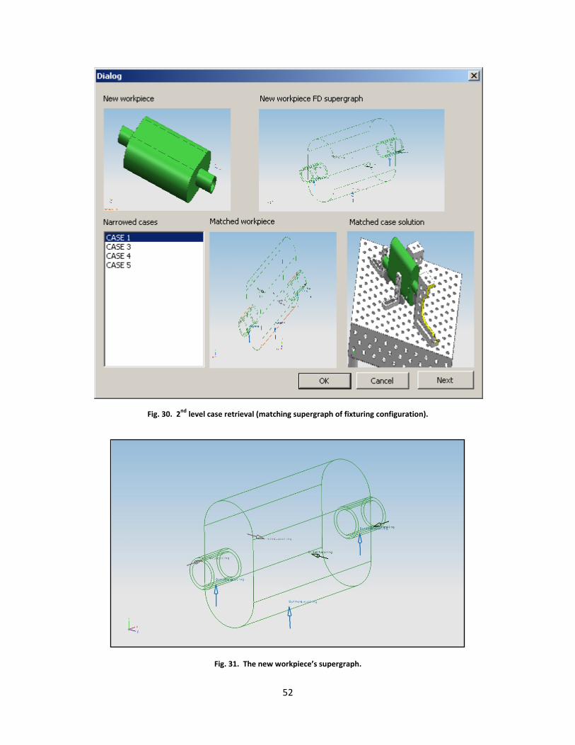
52
Fig. 30. 2nd
level case retrieval (matching supergraph of fixturing configuration).
Fig. 31. The new workpiece’s supergraph.
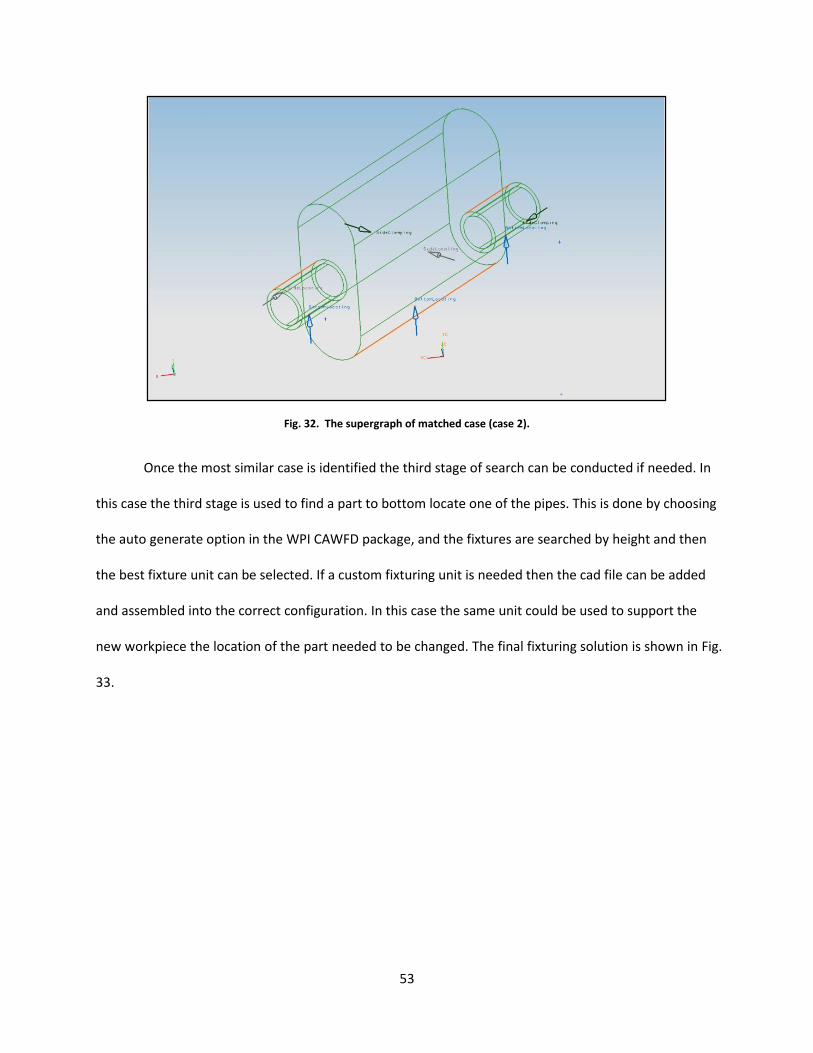
53
Fig. 32. The supergraph of matched case (case 2).
Once the most similar case is identified the third stage of search can be conducted if needed. In
this case the third stage is used to find a part to bottom locate one of the pipes. This is done by choosing
the auto generate option in the WPI CAWFD package, and the fixtures are searched by height and then
the best fixture unit can be selected. If a custom fixturing unit is needed then the cad file can be added
and assembled into the correct configuration. In this case the same unit could be used to support the
new workpiece the location of the part needed to be changed. The final fixturing solution is shown in Fig.
33.
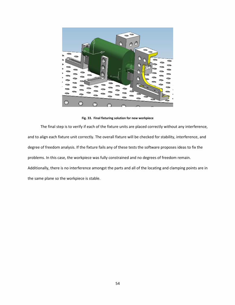
54
Fig. 33. Final fixturing solution for new workpiece
The final step is to verify if each of the fixture units are placed correctly without any interference,
and to align each fixture unit correctly. The overall fixture will be checked for stability, interference, and
degree of freedom analysis. If the fixture fails any of these tests the software proposes ideas to fix the
problems. In this case, the workpiece was fully constrained and no degrees of freedom remain.
Additionally, there is no interference amongst the parts and all of the locating and clamping points are in
the same plane so the workpiece is stable.

55
6. Conclusion and Recommendations
This thesis defined a CBR system that uses similarity analysis and a three stage retrieval system that
incorporates user feedback to produce the best solutions. What was developed was an interface that
directly interacts with the WPI UGS system for computer aided welding fixture design, a system that
indexed both good and bad fixtures, and retrieved the most similar cases. The application of these
methods to the muffler example was meant to show that artificial intelligence methods such as case
based reasoning have the ability to make a significant impact on computer aided fixture design.
The application of both the CAFD and the CBR system provided an environment that allowed the
creation of fixtures for welding assemblies and the retrieval of past cases. The combination of both of
these elements allowed the development of a fixture that based on the historical data stored in cases,
provided the support and versatility needed for identifying solutions to new cases. The creation of an
indexing scheme specific to welding fixtures also helps fixture designers in the future who are creating
similar intelligent systems.
There are some shortcomings to this system. The major one is that while the retrieval process
requires a user to help guide the program. There are some other areas that require further research.
More research can be done regarding the supergraph information. Currently the cosine formula is not
completely effective in producing a well matched solution. If a better solution was created CBR within
this system would be better. Another area of research is the creation of a detailed indexing scheme that
specifies data for multiple types of assembly fixtures would aid in the development of complete CBR
systems. Finally, the creation of a fully automated system with automated adaptation is another area for
future development.

56
Bibliography
Amaral, N., Rencis, J., & Rong, Y. (2005). Development of a finite element analysis tool for fixture design
integrity verification and optimization. The International Journal of Advanced Manufactruing
Technology , 409-419.
Aoyama, T., & Kakinnuma, I. (2006). Optimization of fixture layout by means of the genetic algorithm.
Innovative production machines and systems (IPROMS) .
Applied Design Technologies Inc. (2005). Applied Design Technologies Inc. Retrieved December 6, 2007,
from http://applieddesigntechnologies.com/graphics/FEA-Stress-Plot-Cosmos.jpg
Asante, J. (2008). A combined contact elasticity and finite element-based model for contact load and
pressure distribution calculation in a frictional workpiece-fixture system. The International Journal of
Advanced Manufacturing Technology , 578-588.
BAE Design and Development, Inc. (2009). BAE Design & Development, Inc. Retrieved April 30, 2009,
from BAE Design & Development, Inc: http://www.baedesignanddevelopment.com/
Benhabib, B. (2003). Manufacturing Design, Production, Automation, and Intergration. New York: Marcel
Dekker.
Benhabib, B. (2003). Manufacturing Design, Production, Automation, and Intergration. New York, New
York: Marcel Dekker.
Carr Lane Manufacturing Co. (2008). General Infromation, On-Line Jig and Fixture Handbook, Locating
and Clamping Principles. Retrieved March 11, 2009, from Carr Lane Manufacturing Company:
http://www.carrlane.com/Catalog/index.cfm/29625071F0B221118070C1C513906103E0B05543B0B012
009083C3B2853514059482013180B041D1E173C3B2853524B5A59
Ellig, B. (2008, June). Think Outside the Box. Canadian Metalworking , pp. 87-91.
Eslava, A. (2001). Finite Element Analysis Study on Fixture Workpiece Deformation.
Fan, L. Q., & Kumar, A. S. (2005). XML-based representation in a CBR system for fixture design.
Computer-Aided Design Applications , 339-348.
Flowmaster, Inc. (2009). Flowmaster, Inc. Retrieved April 27, 2009, from Flowmaster, Inc:
http://www.flowmastermufflers.com/mufflers.html
Hou, Z. (n.d.). ME 4512: Introduction to the Finite Element Method. Worcester, MA, USA.
HSPN news. (2007, January 23). Thrush Launches New Welded Muffler, Stainless Steel Glasspacks .
Retrieved April 27, 2009, from HSPN Global News: http://news.hspn.com/articles/1265/1/Thrush-
Launches-New-Welded-Muffler-Stainless-Steel-Glasspacks/Page1.html

57
Hurtado, J. F., & Melkote, S. N. (2001). Improved algorithm for tolerance-based stiffness optimization of
machining fixtures. Journal of Manufacturing Science and Engineering , 720-730.
Kang, Y. (2001). Computer-aided Fixture design verification Phd. Dissertation. Worcester, MA: Worcester
Polytechnic Institute.
Kang, Y., Rong, Y., & Yang, J. C. (2003). Computer-aided fixture design verification. Part 1. The
Framework and modeling. International Journal of Advanced Manufacturing Technology , 827-835.
Kang, Y., Rong, Y., & Yang, J. C. (2003). Computer-aided fixture design verification. Part 2. Tolerance
analysis. The International Journal of Advanced Manufacturing Technology , 836-841.
Kang, Y., Rong, Y., & Yang, J. C. (2003). Computer-aided fixture design verification. Part 3. Stability
analysis. International Journal of Advanced Manufacturing Technology , 842-849.
Kaya, N. (2006). Machining fixture locating and clamping position optimization uing genetic algorithms.
Computers in Industry , 112-120.
Kolodner, J. (1993). Case-Based Reasoning. San Mateo: Morgan Kaufmann Publishers, Inc.
Krishnakumar, K., & Melkote, S. N. (2000). Machining fixture layout optimization using the genetic
algorithm. International Journal of Machine Tools , 579-598.
Krishnakumar, K., Satyanarayana, S., & Melkote, S. N. (2002). Iterative fixture layout and clamping force
optimization using the genetic algorithm. Journal of Manufacturing Science and Engineering , 119-125.
Leake, D. (1996). Case-Based Reasoning. Cambridge: The MIT Press.
Maher, M. L., Balachandran, M. B., & Zhang, D. M. Cased-Based Reasoning In Design. Mahwah:
Lawrence Erlbaum Associates, Inc.
Mervyn, F., Kumar, A. S., & C., N. A. (2005). An adaptive Fixture Design System for Integrated Product
and Process Design. International Conference on Automation Science and Engineering , 87-92.
Mervyn, F., Kumar, A. S., & C., N. A. (2005). Automated synthesis of modular fixture designs using an
evolutionary search algorithm. International Journal of Production Research , 5047-5070.
Peterson Jig and Fixture. (2007). Peterson Jig and Fixture. Retrieved April 28, 2009, from PJF:
http://www.pjfinc.com/steel.htm
Ratchev, S., Phuah, K., & Liu, S. (2007). FEA-based methodology for the predcition of part-fixture
behaviour and its applications. Journal of Material Processing technology , 260-264.
Romheld Austrialia. (2007). Modular Fixture Parts. Retrieved December 9, 2007, from Romheld
Austrialia:
http://images.google.com/imgres?imgurl=http://www.romheld.com.au/UserFiles/Image/Flexible%2520

58
Fixture%2520Parts%2520(228%2520x%2520250).jpg&imgrefurl=http://www.romheld.com.au/sub_prod
ucts.php%3Fcat_id%3D97%26cat_name%3DModular%2BFixture%2BParts&h=250&w=2
Rong, Y., & Zhu, Y. (1999). Computer-Aided Fixture Design. New York: Marcel Dekker, Inc.
Rong, Y., & Zhu, Y. (1999). Computer-Aided Fixture Design. New York, New York: Marcel Dekker, Inc.
Satyanarayana, S., & Melkote, S. N. (2004). Finite Element Modeling of a fixtuere-workpiece contacts:
single contact modeling and experimental verification. International Journal of Machine Tools and
Manufacture , 903-913.
Siebenaler, S. P., & Melkote, S. N. (2006). Prediction of workpiece deformation in a fixture system using
the finite element method. The International Journal of Machine Tools and Manufacture , 51-58.
Subramaniam, V., Kumar, A. S., & Seow, K. C. (2001). A multi-agent approach to fixture design. Journal of
Intelligent Manufacturing , 31-42.
Wallack, A. S. (1996). Generic Fixture Design Algorithm for minimal modular fixture toolkits. Proceedings
of the 1996 IEEE International Conference on Robotics and Automation, (pp. 487-495). Minneapolis.
Wang, H., & Rong, Y. (. (2008). Case Based Reasoning Method for Computer Aided Welding Fixture
Design. Computer-Aided Design 40 , 1121-1132.
Woojin Engineering Co., Ltd. (2003, December 25). Woojin Engineering. Retrieved April 30, 2009, from
Woojin Engineering: http://www.woojinmc.com/html/
Wu, Y., Rong, Y., Ma, W., & LeClair, S. (1998). Automated modular fixture planning: Accuracy, clamping,
and accessibilty analyses. Robotics and Computer-Intergrated Manufacturing 14 , 17-26.
Yuru, Z., & Gaoliang, P. (n.d.).
Zheng, Y., Rong, Y., & Hou, Z. (2008). The study of fixture stiffness. Part II: contact stiffness identification
between fixture compoents. The International Journal of Advanced Manufacturing Technology , 19-31.
Zheng, Y., Rong, Y., & Z, H. (2008). The study of fixture stiffness. Part I: a finite element analysis for
stiffness of fixture units. The International Journal of Advanced Manufacturing Technology , 865-876.

59
Appendix A. XML representation of a sample fixturing solution
- <FDSetup Name="Setup 1" Filepath="\Setup 1.prt">
- <WorkPiece>
<WorkPiece Filepath="\case_2_asm_stp(0).prt" IndexInAssembly="1" />
</WorkPiece>
- <WorkTable Name="WorkTable" ID="WorkTable" Filepath="\WorkTable.prt" ImageFilepath="\">
<Function>7</Function>
<FunctionalHeight MinValue="0.0000" MaxValue="0.0000" />
- <Components>
- <Comp Name="FT-D28-01001-001B" ID="FT-D28-01001-001B" FilePath="\D28-01001-001B(0).prt"
XMLFilePath="\FT-D28-01001-001B.xml">
<IndexInAssembly>1</IndexInAssembly>
</Comp>
</Components>
<AssemblyConstraints />
- <FeaturesGroup Type="SupportingFeatures">
- <FixturingFace Function="5" Name="503-D28-01001-001B" FaceType="UF_ASSEM_planar_face"
ComponentIndex="1">
- <HoleFeatures>
- <HolesPattern>
- <OriginalHole Name="">
<X>-450.000000</X>
<Y>0.000000</Y>
<Z>-450.000000</Z>
</OriginalHole>
- <Dir_Numbers>
<X_dir>9.000000</X_dir>
<Y_dir>0.000000</Y_dir>
<Z_dir>9.000000</Z_dir>
</Dir_Numbers>
- <Dir_Offsets>
<X_dir>100.000000</X_dir>
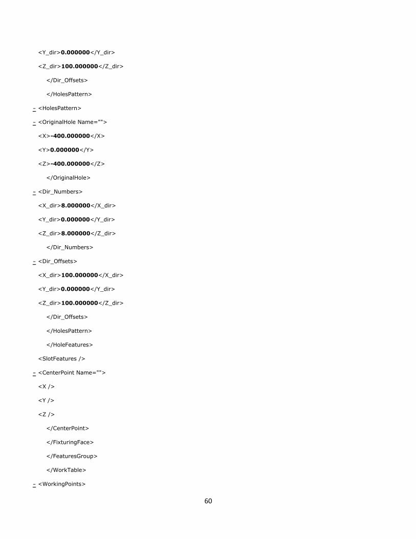
60
<Y_dir>0.000000</Y_dir>
<Z_dir>100.000000</Z_dir>
</Dir_Offsets>
</HolesPattern>
- <HolesPattern>
- <OriginalHole Name="">
<X>-400.000000</X>
<Y>0.000000</Y>
<Z>-400.000000</Z>
</OriginalHole>
- <Dir_Numbers>
<X_dir>8.000000</X_dir>
<Y_dir>0.000000</Y_dir>
<Z_dir>8.000000</Z_dir>
</Dir_Numbers>
- <Dir_Offsets>
<X_dir>100.000000</X_dir>
<Y_dir>0.000000</Y_dir>
<Z_dir>100.000000</Z_dir>
</Dir_Offsets>
</HolesPattern>
</HoleFeatures>
<SlotFeatures />
- <CenterPoint Name="">
<X />
<Y />
<Z />
</CenterPoint>
</FixturingFace>
</FeaturesGroup>
</WorkTable>
- <WorkingPoints>

61
- <SideLocatingPoints>
- <FixturingPoint Name="SideLocating Point 0">
<PointUV>0.0278 -0.0003</PointUV>
<PointOnFace>CAMFD SideLocatingFace 0</PointOnFace>
<PointOnPart>case_2_asm_stp</PointOnPart>
<FixtureUnit />
</FixturingPoint>
- <FixturingPoint Name="SideLocating Point 1">
<PointUV>0.0584 0.1673</PointUV>
<PointOnFace>CAMFD SideLocatingFace 1</PointOnFace>
<PointOnPart>case_2_asm_stp</PointOnPart>
<FixtureUnit />
</FixturingPoint>
</SideLocatingPoints>
- <BottomLocatingPoints>
- <FixturingPoint Name="BottomLocating Point 0">
<PointUV>3.0933 0.1642</PointUV>
<PointOnFace>CAMFD BottomLocatingFace 0</PointOnFace>
<PointOnPart>case_2_asm_stp</PointOnPart>
<FixtureUnit />
</FixturingPoint>
- <FixturingPoint Name="BottomLocating Point 1">
<PointUV>3.1473 0.0375</PointUV>
<PointOnFace>CAMFD BottomLocatingFace 1</PointOnFace>
<PointOnPart>case_2_asm_stp</PointOnPart>
<FixtureUnit />
</FixturingPoint>
- <FixturingPoint Name="BottomLocating Point 2">
<PointUV>3.1359 0.0375</PointUV>
<PointOnFace>CAMFD BottomLocatingFace 2</PointOnFace>
<PointOnPart>case_2_asm_stp</PointOnPart>
<FixtureUnit />

62
</FixturingPoint>
</BottomLocatingPoints>
- <SideClampingPoints>
- <FixturingPoint Name="SideClamping Point 0">
<PointUV>-0.0276 -0.0001</PointUV>
<PointOnFace>CAMFD SideClampingFace 0</PointOnFace>
<PointOnPart>case_2_asm_stp</PointOnPart>
<FixtureUnit />
</FixturingPoint>
- <FixturingPoint Name="SideClamping Point 1">
<PointUV>0.0701 0.1633</PointUV>
<PointOnFace>CAMFD SideClampingFace 1</PointOnFace>
<PointOnPart>case_2_asm_stp</PointOnPart>
<FixtureUnit />
</FixturingPoint>
</SideClampingPoints>
<TopClampingPoints />
</WorkingPoints>
<FixtureSolution />
<AssemblySimulation />
</FDSetup>