A Structured Validation and Verification Method for ... · PDF fileA Structured Validation...
15
A Structured Validation and Verification Method for Automotive Systems considering the OEM/Supplier Interface Kristian Beckers 2 , Isabelle C ˆ ot´ e 2 , Thomas Frese 3 , Denis Hatebur 1,2 , and Maritta Heisel 1 1 paluno - The Ruhr Institute for Software Technology – University Duisburg-Essen, email: {denis.hatebur,maritta.heisel}@uni-due.de 2 Institut f ¨ ur technische Systeme GmbH, Germany, email: {k.beckers,i.cote,d.hatebur}@itesys.de 3 Ford Werke GmbH, email: [email protected] Abstract. The released ISO 26262 standard for automotive systems requires sev- eral validation and verification activities. These validation and verification activ- ities have to be planned and performed jointly by the OEMs and the suppliers. In this paper, we present a systematic, structured and model-based method to plan the required validation and verification activities and collect the results. Planning and the documentation of performed activities are represented by a UML notation extended with stereotypes. The UML model supports the creation of the artifacts required by ISO 26262, enables document generation and a rigorous check of sev- eral constraints expressed in OCL. We illustrate our method using the example of an electronic steering column lock system. Keywords: Safety Management, Verification, Validation, ISO 26262, Automo- tive, UML, OCL, UML4PF, V&V 1 Introduction Developing and constructing road vehicles has become a complex task due to the in- crease of features, such as adaptive cruise control or lane keeping assist functions. The safety aspects of these features have to be taken into account during the product devel- opment. Another fact is that most of these complex systems are distributed. Distributing the system amongst the different parties involved means that the overall system is bro- ken down into several components and/or subsystems provided by different suppliers. This raises the complexity for the manufacturer (OEM), who has to organize the neces- sary V&V activities. With the release of ISO 26262 - Road vehicles – Functional safety in November 2011 [1], the automotive sector benefited from a consistent functional safety process for developing and constructing electric/electronic (E/E) systems. ISO 26262 addresses all levels of development, including definition of functions/features, systems engineering as well as details of software and hardware development. The standard should be applicable to different scenarios for establishing this pro- cess, including e.g., the OEM and any number of suppliers for the distributed systems.
Transcript of A Structured Validation and Verification Method for ... · PDF fileA Structured Validation...

A Structured Validation and Verification Method forAutomotive Systems considering the OEM/Supplier
Interface
Kristian Beckers2, Isabelle Cote2, Thomas Frese3,Denis Hatebur1,2, and Maritta Heisel1
1 paluno - The Ruhr Institute for Software Technology – University Duisburg-Essen, email:{denis.hatebur,maritta.heisel}@uni-due.de
2 Institut fur technische Systeme GmbH, Germany, email:{k.beckers,i.cote,d.hatebur}@itesys.de
3 Ford Werke GmbH, email: [email protected]
Abstract. The released ISO 26262 standard for automotive systems requires sev-eral validation and verification activities. These validation and verification activ-ities have to be planned and performed jointly by the OEMs and the suppliers. Inthis paper, we present a systematic, structured and model-based method to planthe required validation and verification activities and collect the results. Planningand the documentation of performed activities are represented by a UML notationextended with stereotypes. The UML model supports the creation of the artifactsrequired by ISO 26262, enables document generation and a rigorous check of sev-eral constraints expressed in OCL. We illustrate our method using the example ofan electronic steering column lock system.
Keywords: Safety Management, Verification, Validation, ISO 26262, Automo-tive, UML, OCL, UML4PF, V&V
1 Introduction
Developing and constructing road vehicles has become a complex task due to the in-crease of features, such as adaptive cruise control or lane keeping assist functions. Thesafety aspects of these features have to be taken into account during the product devel-opment. Another fact is that most of these complex systems are distributed. Distributingthe system amongst the different parties involved means that the overall system is bro-ken down into several components and/or subsystems provided by different suppliers.This raises the complexity for the manufacturer (OEM), who has to organize the neces-sary V&V activities.
With the release of ISO 26262 - Road vehicles – Functional safety in November2011 [1], the automotive sector benefited from a consistent functional safety process fordeveloping and constructing electric/electronic (E/E) systems. ISO 26262 addresses alllevels of development, including definition of functions/features, systems engineeringas well as details of software and hardware development.
The standard should be applicable to different scenarios for establishing this pro-cess, including e.g., the OEM and any number of suppliers for the distributed systems.

Usually, the OEM division responsible for the development of the system createsthe logical architecture and then distributes requirements to different divisions withinthe OEM responsible for the components. These divisions receive all requirements fromsystems in which their component is involved in, integrate the requirements and cascadethe requirements to the component suppliers. They do the implementation and supplypieces of hardware and software that then have to be integrated into the vehicle.
This distribution includes several challenges: For the requirement engineering, ithas to be determined who has to provide which content at which level of detail. Someof the requirements engineering (RE) has to be done by the OEM and the supplemen-tary RE has to be added by the suppliers. For the verification and validation (V&V), theOEM division responsible for the overall system has to ensure that the V&V tasks aredefined and cascaded to the other divisions and the suppliers. Some aspects can onlybe validated on vehicle level by the OEM division responsible for the system (e.g. theoverall behavior of the system), some aspects can be validated on component level bythe divisions responsible for the components (e.g. the behavior of the component) andother aspects can only be validated using internal interfaces of the component by thesuppliers. When the V&V is performed, the results of the V&V activities at suppliersside and within the different OEM divisions needs to be fed back and collected in an ap-propriate way to support the creation of the safety case. In addition, heterogeneous andconcurrent engineering processes, methods and tools exists within the affected partieswhich need to be harmonized. Communication between OEM and divisions/suppliershas to be organized via requirements as well as verification and validation documents.
Note that verification and validation are not always clearly distinguished in ISO26262. Examples are part 3 section 8.4.5 “Verification of the functional safety concept”where a note mentions, that the same methods can be applied for verification and val-idation or part 4, section 6 “Specification of the technical safety requirements”, whereverification and validation are addressed in the same sub-section. Another example,found in part 3 section 7.4.5, defines the verification of the hazard analysis, which is –according to the definition of the terms in part 1 – more a validation activity. Therefore,we do not distinguish between verification and validation actions and always talk aboutV&V and use the more general term “verification” throughout our paper.
In this paper, we propose a structured method based on UML models supported bya tool for the V&V activities. This work is part of a larger model-based safety require-ments engineering approach in support of ISO 2626 as described in Sect. 3. The papersreferenced there also include V&V in the early development steps, i.e., the V&V offunctional safety requirements regarding the safety goals and technical safety require-ments regarding the functional safety requirements. This paper addresses the V&V ac-tivities in later development steps after handing-over requirements to the divisions andsupplier(s). The advantage of a UML model-based approach is that the different ar-tifacts are explicitly connected instead of having loosely coupled documents. On thisoverall model, consistency checks can be performed. These consistency checks can bespecified with the Object Constraint Language (OCL) from the Object ManagementGroup (OMG) [2].
Our paper is organized as follows: Background to our work is presented in Sect. 2,which is the ISO 26262 standard. We give an overview on our functional safety frame-work in Sect. 3. Section 4 outlines the tool support. Our case study is introduced inSect. 5. Our method including the application on the case study is presented in Sect. 6.
2

This section also describes our UML profile, which can be used to express all relevantISO 26262 artifacts. Section 7 presents related work, while Sect. 8 concludes the paperand gives directions for future work.
2 ISO 26262
ISO 26262 is a risk-based functional safety standard intended to be applied to safety-related systems that include one or more E/E systems and that are installed in seriesproductions of passenger cars with a max gross weight of up to 3500 kg. It addressespossible hazards caused by malfunctions of E/E safety-related systems, including theinteraction of these systems. ISO 26262 was derived from the generic functional safetystandard IEC 61508 [3] and is aligned with the automotive safety life-cycle includingspecification, design, implementation, integration, verification, validation, configura-tion, production, operation, service, decommissioning, and management. ISO 26262provides an automotive-specific risk-based approach for determining risk classes thatdescribe the necessary risk reduction for achieving an acceptable residual risk, calledautomotive safety integrity level (ASIL). The possible ASILs are QM, ASIL A, ASIL B,ASIL C, and ASIL D. The ASIL requiring the highest risk reduction is called ASIL D.For functions with ASIL A, ASIL B, or ASIL C, fewer V&V requirements are given inISO 26262. In case of a QM rating, the normal quality measures applied in the automo-tive industry are sufficient.
Regarding the OEM-supplier interface, ISO 26262 Part 8 requires an appropriatedefinition (e.g. by using a development interface agreement), but as the application ofthe standard should be possible in different project scenarios, the standard does notpredefine a dedicated split of technical responsibilities.
3 Functional Safety Framework
The Ford Integrated process for Functional Safety (FIFS) consists of templates, exam-ples and guidelines in Microsoft Word and Microsoft Excel. These templates, examplesand guidelines were developed and improved (using project feedback) since 2009. Theywere applied in more than 20 projects and cover all parts of ISO 26262 being relevantfor an OEM who does not develop software and hardware. If the templates are appliedaccording to the guidelines, ISO 26262 compliant (work) products are developed. Themethod is based on practical experience in the automotive domain.
Within the V-model applied in ISO 26262, the first step of requirements engineeringis to perform a hazard analysis and risk assessment for the system under consideration.Output of this step is given by the safety goals, describing the highest level of safetyrequirements. In the functional safety concept (FSC), the safety goals from the hazardanalysis are broken down into functional safety requirements. These functional safetyrequirements are mapped to subsystems or components.
The task of the subsequent step is to split the functional safety requirements up intotechnical safety requirements. Within our approach, the technical safety requirementcategories SafetyRelatedFunction, UserInformation, MaintainSafeState Recovery, Ex-ternalFaultHandling, LatentFaultHandling, Decomposition, and Metric are used.With these functional safety requirements and technical safety requirements, the re-quirement activities of the OEM are finalized within the setup chosen for our method.
3

Fig. 1. Profile Part concerning Requirements and Components
The technical safety requirements are cascaded to the other OEM divisions and finallyto the suppliers as described in Sect. 1. and the V&V phase is started.
The method presented in this paper supports the planning and performing of V&Vactivities as well as the documentation of their results (see Sect. 6). It is embedded in theoverall functional safety process according to ISO 26262. The created documentationis an essential part for the subsequent steps that result in the safety case. The safetycase is the argument that the safety requirements for an item are complete and satisfiedby evidence compiled from documents of all ISO 26262 safety activities during thewhole lifecycle. It represents the key argument for the Functional Safety Assessmentand product release and concludes the ISO 26262 development process.
Aiming at tool support, we started to develop a UML profile and a set of OCLconstraints to support the development activities.
The whole approach was presented on the automotive industry conferences VDAAutomotive SYS Conference 4, Baden-Baden Spezial 2012 5 and Safetronic 2014 6.The Electronic Steering Column Lock case study is used in all papers and presentations.
In these papers, we introduced (among others) the following stereotypes (see Fig. 1):– To represent the system to be built the stereotype �Item� is introduced,– Relevant entities in the environment of the item are called domains (�domain�),– Requirements (�Requirement�) extending UML classes with the an attribute for
the requirement text,– safety requirements (�SafetyRequirement�) being special requirements with at-
tributes for the ASIL and the safe state,– safety goals (�SafetyGoal�) as a top-level requirement being a special safety
requirement,– functional safety requirements (�FunctionalSafetyRequirement�), also being spe-
cial safety requirements, systematically derived from the safety goals,– technical safety requirements (�TechnicalSafetyRequirement�), also being spe-
cial safety requirements, systematically derived from the functional safety require-ments and being the input for the supplier,
– components or subsystems (�CompSubsystem�) extending UML classes, and– to show the relation between technical safety requirements and components or sub-
systems, the �refersTo�-dependency was created.
4Presentation on 2012-06-18/20, 2012, Berlin: http://vda-qmc.de/en/software-processes/vda-automotive-sys/
52012-10-10/11, Baden-Baden: http://www.vdi.de/technik/fachthemen/fahrzeug-und-verkehrstechnik/artikel/pressegespraech-auf-der-vdi-tagung-baden-baden-spezial-2012/
62014-11-11/12 Stuttgart: https://www.hanser-tagungen.de/web/index.asp?task=001&vid=201402241659596
4

Table 1. Derived Technical Safety RequirementsID Requirement Purpose CategoryESCL-T-S-Req01000
SSM (Speed Sensor Module) shall measure ve-hicle speed and shall send vehicle speed signalwith quality factor every 20 ms protected withchecksum
Vehicle speed signal is used to determine that thevehicle is at standstill, which is one of the condi-tions that allow steering column locking.
Safety Re-lated Function
ESCL-T-S-Req01010
SSM shall detect faults (including sensor faults)leading to an erroneous vehicle speed informa-tion < PERMITTTED LOCKING SPEED witha tolerance of 2 km/h
For Safety Goal 01, valid vehicle speed is one infor-mation to detect if ESCL locking is allowed. There-fore faults of vehicle speed shall be detected.
Internal FaultHandling
ESCL-T-S-Req01040
SSM shall fulfill the specified target value forPMHF
Metric Requirement for Safety Related Function Metric
4 Tool Support
We use a tool called UML4PF, developed at the University of Duisburg-Essen, andintegrated support for the method to create a safety requirements specification as de-scribed in Sect. 6 into it. UML4PF is based on the Eclipse platform [4] together withits plug-ins EMF [5] and OCL [2]. Our UML-profile is conceived as an Eclipse plug-in,extending the EMF meta-model. The OCL constraints are integrated directly into theprofile. Thus, it is possible to automatically check the constraints using the validationmechanisms provided by Eclipse.
After the developer has drawn some diagram(s) using an EMF-based editor, forexample Papyrus UML [6] and applied our stereotypes, UML4PF provides him or herwith the following functionality: it checks if the developed model is valid and consistentby using our OCL constraints described in Table 5. It returns the location of invalid partsof the model, and generates documentation that can be used for the manual validationand review activities.
5 Case Study
Our case study is an electronic steering column lock (ESCL) system, which was intro-duced as case study in several presentations and papers (see Section 3).
The item definition, the hazard analysis and risk assessment, the safety goals, thefunctional safety requirements, and the technical safety requirements exist as input.
In this paper, we choose the safety goal SG01 “Locking the steering column whenvehicle is moving shall be prevented” as an example from which the following func-tional safety requirement is derived: ESCL-F-S-Req 01: “The steering column shallonly be locked if the physical vehicle speed information is valid (correct and in time)and the absolute value is lower than permitted locking speed. Invalid vehicle speedinformation shall be detected.” From this functional safety requirement, the technicalsafety requirements of different categories given in Table 1 were derived representingthe implementation of the respective functional safety requirement in the speed sensingmodule (SSM).
6 V&V Method and Case Study
We propose a method for planning and documenting performed V&V activities. TheV&V methods need to address the following ISO 26262 topics: For all technical andfunctional safety requirements, a link to an analysis (e.g. FMEA or fault tree analysis(FTA)) is required. For each functional and technical safety requirement, the correctness
5

ext
ern
al
inp
ut
met
hod
inp
ut/
outp
ut
3. Plan Responsibilities and Due Dates
- Detailled Plan for V&V Activities- Validated V&V Activities
- Low Level Requirements- Refined Analysis and Verification Activities
5. Review Feedback for
Technical Safety Requirements Verification
4. Provide Task Feedback for
Technical Safety Requirements
8. Perform Confirmation
Review
2. Plan Verificiation and
Validation Activities
- Refined V&V Activities
- Confirmation Review Results
- Links from Requirements to Safety Analyses
UML4PF ISO26262 Profile*
6. Provide Task Feedback for
Functional Safety Requirements and
Safety Goal
- Feedback for functional safety requirements and safety goals
Safety Analyses
Functional Safety Requirements
* Needed in all subsequent Steps
1. Link Requirements
and Safety Analyses
OEM =+ Supplier
=+ =+ =+
Technical Safety Requirements
7. Review Feedback for
Functional Safety Requirements Verification
=+
Predefined V&V Activities
Supplier Engineering Documentation
=+
- Review Feedback
- Verification Review Results
Fig. 2. V&V Method considering the OEM/Supplier Interface
and the completeness of the detailed V&V method (e.g. a test case in a test specification)needs to be assessed and it needs to be checked that the results of the V&V fulfill theacceptance criteria. From OEM perspective, it has to be ensured that the suppliers havederived and implemented appropriate hardware (HW) and software (SW) requirementsfor each technical safety requirement. This includes the application of the processesand methods as required by ISO 26262. Checking these processes and methods is anadditional V&V step for the OEM. Additionally, the calculation of the HW metrics onsafety goal level is required by ISO 26262, based on the input values provided by thesuppliers. Details on metric calculation and corresponding V&V are provided in [7].
Within our method, we structure the V&V activities as follows: An engineering ac-tivity (e.g. derivation of HW and SW requirements by the supplier(s), or engineeringV&V activities like analyses or testing). An engineering activity feedback (e.g. a ref-erence to the derivation of HW and SW requirements, analyses or test cases). A safetyV&V activity to check if the task feedback is appropriate (e.g. review if the derivationof the HW and SW is sufficiently justified, review if the applied analyses are accordingto ISO 26262, review if all safety aspects of a requirement are covered by test cases). Asafety V&V activity feedback to document the results of the V&V activity.
Our method includes matching the ISO 26262 topics to the different V&V activi-ties. Figure 2 depicts an overview of our method consisting of eight steps in which wehighlight for each activity the contribution of the OEM and its supplier(s). Each stepis described in the subsequent paragraphs. We illustrate the application of these stepswith functional safety requirements and some of the the exemplary technical safetyrequirements introduced in Section 5.
Step 1. Link Requirements and Safety Analyses As input for this step, we need thefunctional and technical safety requirements, and the safety analyses, as well as ourUML-profile. As the OEM is responsible for the overall system, he provides the major-ity of information for this step and requests specific information from involved suppli-ers. The suppliers are reacting upon demand of the OEM. ISO 26262 [1, Part 4: 7.4.3.1]requires that the safety analyses are consistent to functional as well as technical safetyrequirements. To ensure this, a mapping is created in this step: Each functional and tech-nical safety requirement is linked to some part of the safety analyses, i.e., a line item of aFailure Mode and Effect Analysis (FMEA) [8] or a gate or event of a Fault Tree Analysis(FTA) [9]. The output is generated from the input by systematically comparing the ele-ments contained in the analyses with the functional and technical safety requirements.
6

Fig. 3. Safety Analysis Linked to Requirements
Whenever an element in the analyses is found that is also addressed by a requirement,we establish a link between the element and the requirement. The UML4PF ISO 26262profile provides appropriate stereotypes to support this step. We introduce the stereotype�addressedBy�, which extends the UML dependency. This dependency points fromthe analysis element to the corresponding requirement. Additionally, the FTA or FMEAelements need to be imported to the model. They can be represented by UML classeswith the stereotype �FTAGate�, �FTAEvent�, or �FMEALineItem�. UML4PFoffers us the opportunity to run some automated checks, e.g. it is possible to check thatall technical and functional safety requirements address an element of an analysis (seecondition 1C01RA in Table 5 7), and vice-versa (see condition 1C02AR in Table 5), andthe stereotype �addressedBy� points from an analysis element (class with the stereo-type �FTAGate�, �FTAEvent�, or �FMEALineItem�) to a functional or technicalsafety requirement (see condition 1M03AR in Table 5). In the case study, the analysisused for the SSM is the fault tree analysis created during the system design phase. Theanalysis is systematically reviewed to identify the elements representing the functionaland technical requirements: For example, the technical safety requirement ESCL-T-S-Req01000 is represented by a gate block in the FTA (SSM L VSPD FA), describing thatthe SSC transmits a vehicle speed less than the permitted speed threshold even the realspeed is higher or equal to the threshold. This is represented by using the UML classfor �FTAGates� and the stereotype �addressedBy� in the class diagram. With thetool support, it is checked that all functional safety requirements and technical safety re-quirements are connected to an analysis element with the stereotype �addressedBy�.The result of this step is depicted in Fig. 3.
Step 2. Plan V&V Activities As input for this step, we use the safety goals, the func-tional safety requirements, and the technical safety requirements with their categoriesand the components that realize these requirements. For each safety requirement certainV&V activities are necessary to fulfill different ISO 26262 requirements. An essentialpart of our method is a set of pre-defined V&V-activities (see Table 2). Taking projectexperience into account, we have defined these activities in a way that the ISO 26262requirements ([1, Part 4, 6.4.2.2] for �InternalFaultHandlingVaV�, [1, Part 4, 6.4.2.2]for �LatentFaultHandlingVaV�, [1, Part 4, 7.4.3.4/5] for �PMHFVaV�, [1, Part 6,9.4] for �HW SWDerivationVaV�, [1, Part 6, 10.4] for �HW SWVerificationVaV�,[1, Part 4, 8.4.3/4] for �SRSVerificationSpecVaV�, and [1, Part 4, 8.4.3/4] for �SRS-VerificationResultVaV�) can be fulfilled. For example for technical safety requirementsof category “SafetyRelatedFunction”, we propose the following V&V activities:
– �HW SWDerivationVaV�: The engineering activity is the derivation of detailedHW and SW requirements for each technical safety requirement. The engineering
7The first number refers to the step in the procedure, C is for consistency checks, M is forchecks considering correct modeling, G is for generation expressions; the next number is thenumber of the check within the step, and the last characters are an abbreviation of the description.
7

Table 2. V&V activities depending on the verified safety requirement type/categoryRequirement Category and ASIL V&V activities
�SafetyGoal� with ASIL C-D �SG HW Metric��FunctionalSafetyRequirement� (or derived) with QM has to be handled according to normal automotive processes�FunctionalSafetyRequirement� (or derived) with ASIL A-D �FSCVerificationSpecVaV�,�FSCVerifiactionResultVaV��TechnicalSafetyRequirement� (or derived) with QM has to be handled according to normal automotive processes�SafetyRelatedFunction� or �Decomposition� or�EmergencyOperationRequirement� or�UserInformation� or�MaintainSafeStateRecovery� with ASIL A-D
�HW SWDerivationVaV�, �HW SWVerificationVaV�,�VerificationSpecificationVaV�,�SRSVerificationResultVaV�
�InternalFaultHandling� with ASIL A-D �InternalFaultHandlingVaV�, �HW SWDerivationVaV�,�HW SWVerificationVaV�, �VerificationSpecificationVaV�,�SRSVerificationResultVaV�
�ExternalFaultHandling� with ASIL A-D �HW SWDerivationVaV�, �HW SWVerificationVaV�,�VerificationSpecVaV�,�SRSVerificationResultVaV�
�LatentFaultHandling� with ASIL A-D �LatentFaultHandlingVaV�, �HW SWDerivationVaV�,�HW SWVerificationVaV�, �SRSVerificationSpecVaV�,�SRSVerificationResultVaV�
�Metric� with ASIL C-D �PMHFVaV�,�SRSVerificationSpecVaV��SafetyRelatedFunction� with ASIL A-D �HW SWDerivationVaV�, �HW SWVerificationVaV�,
�SRSVerificationSpecVaV�,�SRSVerificationResultVaV�
activity feedback is a reference to HW and SW requirements and the correspondingsafety analysis, the safety V&V activity is the review of this feedback.
– �HW SWVerificationVaV�: The engineering activity is the verification of the im-plemented HW and SW requirements. The engineering activity feedback is the ref-erence to the component level verification measures, consisting of e.g. componenttest specifications and analyses and as safety V&V activity the review of this feed-back.
– �VerificationSpecificationVaV�: The engineering activity is the creation of a testcase for the technical safety requirement. The engineering activity feedback is areference to the test case, e.g. as part of a test specification, and the safety V&Vactivity is the review of this feedback.
– �SRSVerificationResultVaV�: The engineering activity is the execution and doc-umentation of the verification. The engineering activity feedback is the referenceto the test report containing the results of the test case as feedback and the safetyV&V activity is the review of this feedback.
This step is usually performed by the OEM. The purpose of this step is to ensure thatall safety related aspects of each safety requirement are covered by V&V activities. Theinput is used to plan which V&V activities have to be performed. The V&V activitiesare specific depending on the verified requirement. In Table 2, we show which activitiesare necessary for the different requirement categories. Tables 3 and 4 show all pre-defined details for the activities to be performed, as well as review criteria.In this step, we create classes with the stereotypes from the second column given inTable 2. Additionally, we create dependencies with the stereotype �verifies� fromthe classes with a stereotype derived from �VaV� to the corresponding requirement.The tool can generate the aforementioned classes and dependencies (see 2G01DR inTable 5). It can be checked that the stereotype �VaVActivity� is not used directly.Instead only its specialized stereotypes (see condition 2M02NV in Table 5) have beenapplied. For example, the technical safety requirement of category SafetyRelatedFunc-tion gets the V&V activities as described in Section 6. Figure 5 shows the results forone example requirement of the case study.Step 3. Plan Responsibilities and Due Dates As input for this step, we use the out-put of Step 2. We can distinguish between different V&V activities. V&V activities
8
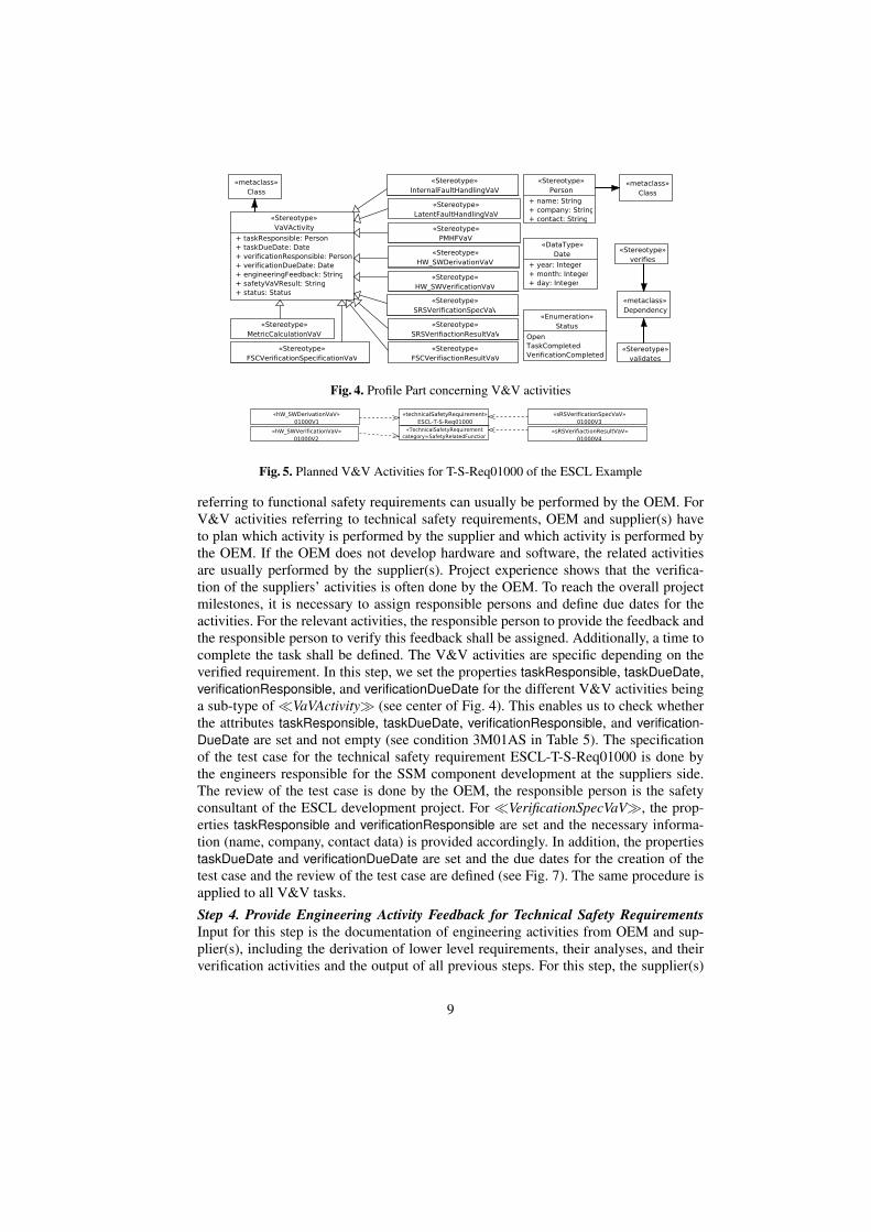
Fig. 4. Profile Part concerning V&V activities
Fig. 5. Planned V&V Activities for T-S-Req01000 of the ESCL Example
referring to functional safety requirements can usually be performed by the OEM. ForV&V activities referring to technical safety requirements, OEM and supplier(s) haveto plan which activity is performed by the supplier and which activity is performed bythe OEM. If the OEM does not develop hardware and software, the related activitiesare usually performed by the supplier(s). Project experience shows that the verifica-tion of the suppliers’ activities is often done by the OEM. To reach the overall projectmilestones, it is necessary to assign responsible persons and define due dates for theactivities. For the relevant activities, the responsible person to provide the feedback andthe responsible person to verify this feedback shall be assigned. Additionally, a time tocomplete the task shall be defined. The V&V activities are specific depending on theverified requirement. In this step, we set the properties taskResponsible, taskDueDate,verificationResponsible, and verificationDueDate for the different V&V activities beinga sub-type of �VaVActivity� (see center of Fig. 4). This enables us to check whetherthe attributes taskResponsible, taskDueDate, verificationResponsible, and verification-DueDate are set and not empty (see condition 3M01AS in Table 5). The specificationof the test case for the technical safety requirement ESCL-T-S-Req01000 is done bythe engineers responsible for the SSM component development at the suppliers side.The review of the test case is done by the OEM, the responsible person is the safetyconsultant of the ESCL development project. For �VerificationSpecVaV�, the prop-erties taskResponsible and verificationResponsible are set and the necessary informa-tion (name, company, contact data) is provided accordingly. In addition, the propertiestaskDueDate and verificationDueDate are set and the due dates for the creation of thetest case and the review of the test case are defined (see Fig. 7). The same procedure isapplied to all V&V tasks.
Step 4. Provide Engineering Activity Feedback for Technical Safety RequirementsInput for this step is the documentation of engineering activities from OEM and sup-plier(s), including the derivation of lower level requirements, their analyses, and theirverification activities and the output of all previous steps. For this step, the supplier(s)
9

Fig. 6. V&V Confirmation Review of ESCLExample
Fig. 7. V&V Activities for SRS of ESCL Ex-ample, Steps 3 and 4
provide necessary information to complete the requirements and V&V activities onHW and SW level. The OEM divisions or supplier(s) provide test specification, testresults and safety analyses. Purpose of this step is to collect information according tothe engineering activities as specified in Table 3. The output of this step is the feed-back on the engineering activities (see Table 3) for all technical safety requirements. Inthis step, we set the attribute engineeringFeedback in the classes with the stereotypes�InternalFaultHandlingVaV�, �LatentFaultHandlingVaV�, �HW SWDerivationVaV�, �PMHFVaV�, �HW SW VerificationVaV�, �SRSVerificationSpecVaV�,�SRSVerificationResultVaV�, �FSCVerificationSpecVaV�, and �FSCVerificationResultVaV� (see Fig. 4). Depending on the stereotype assigned to the technical safetyrequirement, the information or a reference to this information should be provided bythe OEM or the supplier(s) as described in Table 3, column ’Feedback’.It can be checked that the attribute engineeringFeedback is set and not empty (see con-dition 4M01AS in Table 5). After the tasks are performed, the task feedback is insertedby the persons assigned to the task. For the selected example, the supplier engineercreates a test case for the component SSM, covering ESCL-T-S- Req01000. This testcase is part of the test specification “Testplan SSM v12.02.pdf”, therefore the engineerprovides this information, including a reference to the document section containing thetest case. For �VerificationSpecVaV�, the attribute engineeringFeedback is set andthe received information is inserted (see Fig. 7).
Step 5. Safety V&V for Technical Safety Requirements Input for this step is the en-gineering activity feedback of the OEM or supplier from Step 4 and the output of allprevious steps. A different engineer from the OEM and in some cases from the sup-plier reviews the included or referenced information. For all technical safety require-ments, the ISO 26262 [1, Part 4, 6.4.6] requires a verification review. Output of thisstep is the safety V&V activity result. It is checked if all requirements given in col-umn “Safety V&V Activity“ for the stereotype of the V&V activity assigned to thetechnical safety requirement in Table 3 are fulfilled. In this step, we set the attributesafetyVaVResult of the classes with the stereotypes �InternalFaultHandlingVaV�,�LatentFaultHandlingVaV�, �HW SWDerivationVaV�, �PMHFVaV�, �HW -SWVerificationVaV�, �SRSVerificationSpecVaV�, and �SRSVerificationResultVaV�(see Fig. 4). It can be checked that the attribute verificationReviewResult is set and notempty (see condition 5M01AS in Table 5). For the selected example, the OEM SafetyConsultant reviews the referenced test case and checks it against ESCL-T-S- Req01000.The review result is, that the test case is correctly defined and addresses all safety rel-evant aspects of the technical safety requirement. For �VerificationSpecVaV�, the at-
10

Table 3. V&V activities for SRSStereotype Engineering Activity / Feedback Safety V&V Activity
�InternalFaultHandlingVaV� see [7] for more details see [7] for more details�LatentFaultHandlingVaV� see [7] for more details see [7] for more details�PMHFVaV� see [7] for more details see [7] for more details�HW SWDerivationVaV� To ensure a sound component
design, the component providershall derive HW and SW require-ments for the technical safety re-quirement. A reference to this in-formation should be inserted.
The HW and SW requirements for the Technical Safety Require-ment and the implementation process shall be assessed. It shall bechecked that:
– the HW and SW safety requirements, the HW and SW inter-face requirements and the Component Design are correctly de-rived from the Technical Safety Requirement,
– a Safety Analysis (e.g. FTA) to determine faults leading tothe violation of the Technical Safety Requirement is complete(e.g. inputs) and correct (e.g. logic), and
– the HW/SW Design (including internal and external inter-faces) is appropriate and corresponds to Safety Analysis .
To achieve this, the component provider provides input and theOEM reviews a sample to assess the component provider processesand safety analyses.
�HW SWVerificationVaV� The component provider shallverify the implementation of theHW and SW requirements inthe component. A reference tothe verification documentation(e.g. review reports, analyses, testcases) should be inserted.
The V&V of the component shall be assessed. It shall be checkedthat
– . . . see [7] for more details
�SRSVerificationSpecVaV� A verification specification for thetechnical safety requirement shallbe generated (including activityand acceptance criteria consider-ing parameters that can be identi-fied) in order to verify the correctimplementation of the TechnicalSafety Requirement (e.g. Fault in-sertion, Safety Function testing,review of the implementation). Areference to the verification spec-ification should be provided .
The V&V of the component shall be assessed. It shall be checkedthat
– the test specification to verify the effectiveness and the failurecoverage of the safety mechanisms are correct and complete,
– the stated failure rates (e.g. in FMEDA) are justified by ro-bustness testing specified in a qualification plan for the HWcomponents and the test results are documented (optional forphase 1), and
– the HW metrics calculation (e.g. by FMEDA or FTA) as de-fined in ISO 26262 Part 5 (provide evidence that the targetvalues, specified in the Safety Requirement Specification, arefulfilled by the design) is correct and complete.
To achieve this, the component provider provides input and theOEM reviews a sample to assess the component verification andmetric calculation (e.g. FTA, FMEDA).
�SRSVerificationResultVaV� The verification shall be executedas specified and the results shallbe documented. A reference toverification results shall be given.
The verification results from the V&V activities (e.g. test cases)shall be assessed and validated. This can be done by a technicalreview of the V&V specification.
tribute safetyVaVResult is set to “Test case is appropriate” and the information is in-serted. Finally, the property status is set to “VerificationCompleted” (see Fig. 7).Step 6. Provide Engineering Activity Feedback for Functional Safety Requirementsand Safety Goals Input for this step is the documentation of engineering activity of thesupplier or OEM and the output of all previous steps. For this step, usually the OEMdocuments or references the required information. Purpose of this step is to collectinformation according to the engineering activities as specified in Table 4. We spec-ified these activities in a way that the ISO 26262 requirements ([1, Part 4, 7.4.3] for�SG HW Metric�, [1, Part 4, 8.4.3/4] for �FSCVerificationSpecVaV�, and [1, Part4, 8.4.3/4] for �FSCVerificationResultVaV�) can be fulfilled. The output of this stepis the feedback on the engineering activities given in Table 4 for all functional safetyrequirements and safety goals. In this step, we set the attribute engineeringFeedbackof the classes with the stereotypes �SG HW Metric�, �FSCVerificationSpecVaV�,and �FSCVerifiactionResultVaV� (see Fig. 4). Depending on the stereotype assignedto the functional safety requirement or safety goal, the information or a reference tothis information should be provided as described in Table 4. It can be checked that theattribute engineeringFeedback is set and not empty (see condition 6M01AS in Table 5).
11

Table 4. V&V activities for FSCStereotype Engineering Activity / Feedback Safety V&V Activity
�SG HW Metric� HW metrics shall be calculated on safety goallevel by the OEM.
Result and conclusions of the HW metrics calcula-tion on safety goal level shall be assessed and vali-dated. It is checked if the quantitative metrics (cal-culated on Safety Goal level) fulfill the ASIL relatedrequirements and is correctly calculated by a techni-cal review of the safety analyses.
�FSCVerificationSpecVaV� A verification specification shall be created, e.g.a test specification. This verification specifica-tion shall include a unique identification of theverified work product, a reference to the verifica-tion plan, specification of verification includingall relevant parameters, the configuration of theverification environment and verification toolstogether with calibration data The OEM shallprovide a reference to the verification specifica-tion for the referenced functional safety require-ment.
The correctness and the completeness of the verifica-tion specification shall be assessed and validated by atechnical review and the result shall be documented.
�FSCVerificationResultVaV� The verification shall be performed and the re-sults shall be documented. This documentationshall include an unambiguous statement whetherthe verification passed or failed, including the ra-tionale for failure and possible suggestions forchanges in the verified work product. The OEMshall provide a reference to the verification resultfor the referenced functional safety requirement.
It shall be checked that the results of the performedverification activity fulfill the specified acceptancecriteria. This can be done by checking the corre-sponding and referenced verification report.
Step 6 is performed for the functional safety requirements in the same manner as Step4 for the technical safety requirement example.Step 7. Safety V&V for Functional Safety Requirements Input for this step is the engi-neering activity feedback referenced in Step 6 and the output of all previous steps. A dif-ferent engineer from the OEM and in some cases from the supplier reviews the includedor referenced information. For all functional safety requirement, the ISO 26262 [1, Part3, 8.4.5] requires a verification review. Output of this step is the safety V&V activityresult. It is checked if all requirements given in column “Safety V&V Activity“ for thestereotype of the V&V activity assigned to the functional safety requirement or safetygoal in Table 4 are fulfilled. In this step, we set the attribute safetyVaVResult of theclasses with the stereotypes �InternalFaultHandlingVaV�, �LatentFaultHandling-VaV�, �HW SWDerivationVaV�, �PMHFVaV�, �HW SWVerificationVaV�,�SRSVerificationSpecVaV�, and �SRSVerificationResultVaV� (see Fig. 4).It can be checked that the attribute safetyVaVResult is set and not empty (see condition7M01AS in Table 5). Step 7 is performed for the functional safety requirements in thesame manner as Step 5 for the technical safety requirement example.Step 8. Perform Confirmation Review ISO 26262 requires to perform a confirmationreview of the V&V activities. Input for this step is the output of all previous steps. Thisstep is usually performed by the OEM. ISO 26262 [1, Part 2, 6.4.7] requires a confirma-tion review by a person independent from the division responsible for the developmentof the system. We provide a detailed checklist (addressing all ISO 26262 requirements)to support this review. The output is the confirmation that the V&V activities are pre-formed according to ISO 26262. To perform this step, an independent person checks theV&V activities regarding the ISO 26262 requirements. In this step, we set the attributesin a class with the stereotype �VaVConfirmation�. The person performing the reviewand his/her independence level according to ISO 26262 (1=’different person’, 2=’differ-ent team’, 3=’different company or organization’) is set to the corresponding attributesreviewer and independenceLevel. The person doing the confirmation review checks thefollowing:
12

– HW metrics values have been calculated, documented and assessed for each safetygoal.
– Verification methods have been specified and verified for all functional safety re-quirements.
– The verifications have been performed and results have been checked for all func-tional safety requirements.
– The component providers have provided the information to complete the technicalsafety requirements and these information have been validated.
– The HW and SW requirements (derived by the component providers) have beendocumented and checked.
– The verification of the HW and SW requirements (performed by the componentproviders) have been documented and checked.
– Verification methods for the technical safety requirements have been generated,validated and assessed (including activity and acceptance criteria).
– The verifications have been performed and results have been checked for all tech-nical safety requirements.
The reviewer sets the corresponding attributes to true or false. If a statement cannot beconfirmed, a comment is given. Additionally, the date of the review is set. It can bechecked that if one of the attributes is false, the attribute comment is set (see condition7C01CO in Table 5), that all attributes are set (see condition 7C02AT), and that foreach item a V&V confirmation is performed (see condition 7M03VV). Additionally,overviews of the performed V&V activities can be generated to support the confirmationreview (see condition 7G0GVV).
The confirmation review by an independent person is performed after all previoussteps are completed.
For the selected example, an external safety consultant reviews the V&V reportand sets all attributes in the class with the stereotype �VaVConfirmation� as shownin Fig. 6. As the Safety Consultant is from an independent company, the attribute in-dependenceLevel is set to 3. For this element of our case study, all boolean attributesare set to true except HW SWVerificationVaVOK and SRSVerificationResultVaVOK sincethe SSM supplier has not provided test results from the detailed HW and SW testingand from the testing of the technical safety requirement. The attribute comment is setaccordingly. Finally, the attribute date is set to the date of the confirmation review. Ifthe corresponding attributes are set to “false”, the problem needs to be addressed andthe confirmation review will be repeated. When all V&V activities are completed, thecorresponding attributes are set to “true” and the confirmation review is passed, the cre-ation of the V&V report is closed and the functional safety process proceeds with itsnext step, the creation of the safety case. Herein the V&V report is used as an inputdocument.
This step concludes our method. All the created documentation is an essential partfor the subsequent steps that result in the safety case.
7 Related Work
We are not aware of any publication about a model-based structured validation and ver-ification of automotive systems with a focus on the OEM-supplier interface for automo-tive systems equipped with integrity checks. Maropoulos et al. [10] presented a survey
13

Table 5. Validation Conditions (excerpt)Step ID Condition1 1C01RA All technical and functional safety requirement address an element of an analysis.1 1C02AR All elements of the analyses are addressed by technical and functional safety requirement.1 1M03AR The stereotype �addressedBy� points from a an analysis element (class with the stereotype �FTAGate�,
�FTAEvent�, or�FMEALineItem�) to a functional or technical safety requirement.2 2G01DR Generate these classes and dependencies as described in Table 2.2 2M02NV The stereotype�VaVActivity� is not directly used.3 3M01AS The attributes taskResponsible, taskDueDate, verificationResponsible, and verificationDueDate are set and
not empty.... ... ...
of industrial verification and validation efforts. The report presents evidence that veri-fication and validation of products and processes is vital for complex products and inparticular modelling and planning of such methods are an ongoing research challenge.Sinz et al. [11] used formal methods to validate automotive product configuration data.In contrast to our work, their method specifically focuses on detecting inconsistenciesin product configurations of vehicles to support business decisions. Instead we focuson technical verification and validation efforts. Bringman et al. [12] described the im-pact model-driven design has in the automotive industry and showed how models canbe used to derive test cases during different steps of the automotive product lifecycle.In contrast to our work Bringman et al. focus exclusively on model-based testing ofautomotive systems. Dubois et al. [13] presented a method for model-based validationand verification efforts to check if the final product matches initial requirements. Incontrast to our work Dubois et al. focus on using UML-based models to create testcases for more detailed implementation models in e.g. SIMULINK. Montevechi et al.[14] focuses on the simulation of processes in the automotive industry. Their method-ology builds simulation models to analyse which combinations of variables can leadto problems. Within the automotive industry, different activities are started to extendthe safety processes with model-based system engineering aspects, mainly focusing onarchitecture description8 and semiautomatic safety analyses [15].
8 Conclusions and Future Work
Our method has been applied to several Ford of Europe projects. However, the formalvalidation conditions and tool support was not used in these projects and was developedas contribution for this paper. We are confident that this contribution will ensure thesame consistency and correctness of future verification & validation with less effortthan the manual approach currently used. The main contributions of our approach are:
Structured Method helping to– ensure consistency between the safety requirements, safety analyses and safety
V&V,– define a complete set of V&V activities, including reviews, analyses, simula-
tions and tests by using pre-defined V&V activities based on the category ofthe requirement,
– allocate the V&V activities between OEM and the involved suppliers,– define due dates,– collect and assess the V&V results for all requirements, and
8Electronics Architecture and Software Technology - Architecture Description Language,http://www.east-adl.info/
14
– provide input to the safety caseUML Profile for expressing all elements relevant for an ISO 26262-compliant safety
verification and validation, including traceability to the functional and technicalsafety requirements and the safety analyses.
OCL Checks concerning consistency and completeness of the V&V activities. Thus,we provide a computer-aided technique to discover errors in the V&V activitiescaused by inconsistencies or errors in one or more (UML) diagrams.
The V&V report including the supplier interface in practice is currently document-based using spreadsheet-processing tools from Microsoft Office. We propose to con-duct the analysis on UML models and to create tables from the models for the V&Vreport. Thus, we use a model-based approach, but the suppliers will receive the sametype of documentation they are used to. In the future, we will extend the approach toSafety Analysis and Safety Management. Currently, Ford is implementing tool supportin NoMagic’s MagicDraw. Ford is also creating import and export functionalily for theircurrent templates and is developing an interface to requirements management tools.
Acknowledgments. The authors thank Nelufar Ulfat-Bunyadi and the anonymous re-viers for their valuable feedback on the paper.
References1. International Organization for Standardization (ISO): Road Vehicles – Functional Safety.
ISO 26262 (2011)2. UML Revision Task Force: OMG Object Constraint Language: Reference (February 2010)3. International Electrotechnical Commission (IEC): Functional safety of electrical/electron-
ic/programmable electronic safety-relevant systems. IEC 61508 (2000)4. Eclipse Foundation: Eclipse - Development Platform. (2011) http://www.eclipse.org/.5. Eclipse Foundation: Eclipse Modeling Framework Project (EMF) (2012)
http://www.eclipse.org/modeling/emf/.6. Atos Origin: Papyrus UML Modelling Tool. (2011) http://www.papyrusuml.org/.7. Beckers, K., Cote, I., Frese, T., Hatebur, D., Heisel, M.: A structured vali-
dation and verification method for automotive systems considering the oem/-supplier interface technical report. Technical report (2015) https://www.uni-due.de/imperia/md/content/swe/papers/vav2015tr.pdf.
8. Safety Management System and Safety Culture Working Group (SMS WG): Guidance onhazard identification. Technical report (2009)
9. Leveson, N.: Safeware: System Safety and Computers. Addison-Wesley (1995)10. Maropoulos, P.G., Ceglarek, D.: Design verification and validation in product lifecycle.
CIRP Annals - Manufacturing Technology 59(2) (2010) 740–75911. Sinz, C., Kaiser, A., Kuchlin, W.: Formal methods for the validation of automotive product
configuration data. Artif. Intell. Eng. Des. Anal. Manuf. 17(1) (2003) 75–9712. Bringmann, E., Kramer, A.: Model-based testing of automotive systems. In: Software Test-
ing, Verification, and Validation, 2008 1st International Conference on. (April 2008) 485–49313. Dubois, H., Peraldi-Frati, M., Lakhal, F.: A model for requirements traceability in a het-
erogeneous model-based design process: Application to automotive embedded systems. In:Proceedings of ICECCS. (2010) 233–242
14. Montevechi, J.A.B., de Pinho, A.F., Leal, F., Marins, F.A.S.: Application of design of exper-iments on the simulation of a process in an automotive industry. In: Proceedings of WSC.WSC ’07, IEEE Press (2007) 1601–1609
15. Adler, R., Domis, D., Hofig, K., Kemmann, S., Kuhn, T., Schwinn, J.P., Trapp, M.: Integra-tion of component fault trees into the uml. (2011) 312–327
15