A Strong Performer! - Termate · [email protected] +44 (0)115 978 4652 Termate’s MX Busbar...
10
[email protected] +44 (0)115 978 4652 Termate’s MX Busbar supports are the advanced solution to traditional supports. A Strong Performer! 1 Wide range of pole, bar and phase centres 1 Icw ratings up to 65kA /3sec 1 Self extinguishing: UL94-V0 1 Strong and lightweight 1 IEC 61439 compliant
Transcript of A Strong Performer! - Termate · [email protected] +44 (0)115 978 4652 Termate’s MX Busbar...
[email protected]+44 (0)115 978 4652
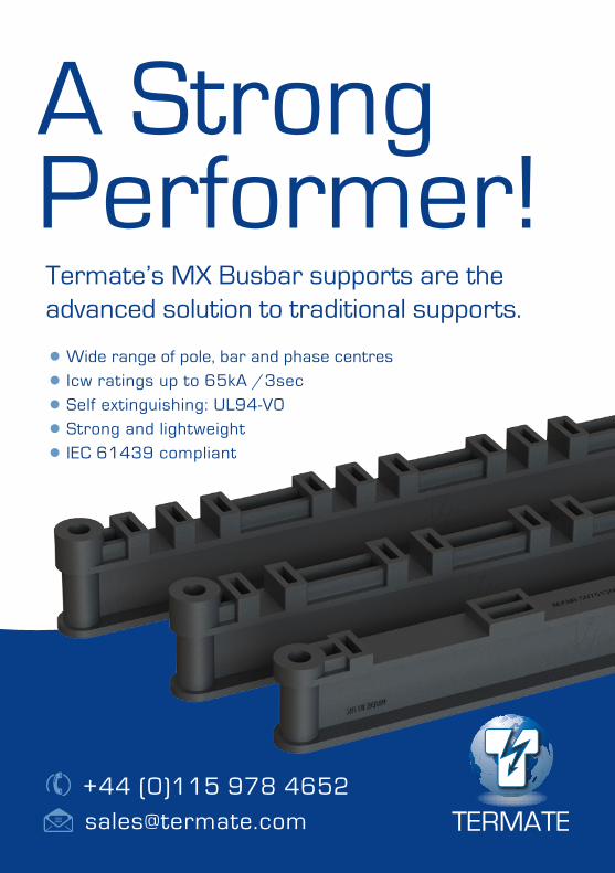
Termate’s MX Busbar supports are the advanced solution to traditional supports.
A Strong Performer!
1 Wide range of pole, bar and phase centres1 Icw ratings up to 65kA /3sec1 Self extinguishing: UL94-V01 Strong and lightweight1 IEC 61439 compliant

Termate have manufactured high performance components since 1956, supplying a global customer base from our U.K. headquarters.
For over 50 years we have independently tested our products to ensure
that they meet and exceed the demands of international standards including
IEC 61439. We work with leading test houses and certification bodies
including kATF, ASTA and Dekra.
Our products offer superb performance and longevity, incorporating materials
manufactured to our specification. We listen to our customers requirements
and respond, which has led to the introduction of versatile products. These can
be used in more applications reducing the total costs to our partners.
We are well known by our customers for the detailed application
engineering and the first class customer service we offer.
This leaflet displays our range of MX Busbar Supports, part of our
LV Power Products Range which comprises various types of Busbar
Supports, Busplugs, Stand-offs, Through Wall Bushings, and Components
for Withdrawable Systems. These products are all manufactured with the
latest equipment at our facility in Nottingham.
We hope that our MX Busbar Supports are of interest. If you would like to
receive a quote, application help or learn more about any of our products,
we would be delighted to hear from you.
You can find out more information by visiting our website at
www.termate.com, alternatively you can email our sales team at
[email protected] or call +44 (0)115 978 4652.

3 Pole : 10 mm Conductor Busbar Supports
Material: Glass Reinforced Polyamide 6.6
Conductor Temp: 140°C†
Flammability: UL94-VO
Glow Wire: 960°C
Equipment Voltage Ue: 1000V
Insulation Voltage Ui: 1000V
Impulse Voltage Uimp
: 12kV
Properties
ReferenceTermate Icw
RatingType Part NumberNumber of
PolesConductor Width mm
Phase Centres
Bars Per Pole
3 10 82 1 65kA 3s 1 MXM8213NS
3 10 82 2 65kA 3s 2 MXM8223NS
3 10 110 1 65kA 3s 1 MXM11013NS
3 10 110 2 65kA 3s 2 MXM11023NS
Measurements in mm
Part NumberL Length
W Width
H Height
SW Slot Width
H1 Base to
Bar Height
SCSlot Centres
FCFix Centres
CClearance
273 20 44.7 10.1 32 82 253 34.5 MXM8213NS
273 20 44.7 10.1 32 82 253 24.5 MXM8223NS
350 20 44.7 10.1 32 110 330 45 MXM11013NS
350 20 44.7 10.1 32 110 330 35 MXM11023NS
TYPE 2
TYPE 1
† In line with the limits set out in IEC 61439, insulating components in contact with conductors may be required to continuously operate at an average of 140°C (Max 145°C). This range of products meets the requirement, the material for them being assigned thermal class F established using methods similar to IEC 60085.
Steel StuddingM8
Steel StuddingM8
H1H H
L
SWSC* *
SC C
FC
W
M8 Recommended Tightening Torque 10 Nm
Please refer to the spacer selection table for recommended spacers which must be ordered separately.If using another method of fixing, please take into account the reduced creepage and clearance distances to the adjacent busbar.
*For the 2 bar version the dimension of the pip between the bars is the same as the conductor width.

4 Pole : 6 mm Conductor Busbar Supports
Material: Glass Reinforced Polyamide 6.6
Conductor Temp: 140°C†
Flammability: UL94-VO
Glow Wire: 960°C
Equipment Voltage Ue: 1000V
Insulation Voltage Ui: 1000V
Impulse Voltage Uimp
: 12kV
Properties
Measurements in mm
Part NumberL Length
W Width
H Height
SW Slot Width
H1 Base to
Bar Height
SCSlot Centres
FCFix Centres
CClearance
350 20 45.5 6.1 32 82 330 28 MX68224NS
273 20 45.5 6.7 32 60 253 28.5 MXB6014NS
273 20 45.5 6.7 32 65 253 20.5 MXB6514NS
273 20 45.5 6.5 32 65 253 14 MXB6524NS
ReferenceTermate Icw
RatingType Part NumberNumber of
PolesConductor Width mm
Phase Centres
Bars Per Pole
4 6 82 2 65kA 3s 2 MX68224NS
4 6.3 60 1 50kA 1s 1 MXB6014NS
4 6.3 65 1 50kA 1s 1 MXB6514NS
4 6.3 65 2 65kA 3s 2 MXB6524NS
TYPE 2
TYPE 1
† In line with the limits set out in IEC 61439, insulating components in contact with conductors may be required to continuously operate at an average of 140°C (Max 145°C). This range of products meets the requirement, the material for them being assigned thermal class F established using methods similar to IEC 60085.
Steel StuddingM8
Steel StuddingM8
H1H H
L
SWSC* *
SC C
FC
W
M8 Recommended Tightening Torque 10 Nm
Please refer to the spacer selection table for recommended spacers which must be ordered separately.If using another method of fixing, please take into account the reduced creepage and clearance distances to the adjacent busbar.
*For the 2 bar version the dimension of the pip between the bars is the same as the conductor width.

4 Pole : Conductor 10 mm Busbar Supports
Material: Glass Reinforced Polyamide 6.6
Conductor Temp: 140°C†
Flammability: UL94-VO
Glow Wire: 960°C
Equipment Voltage Ue: 1000V
Insulation Voltage Ui: 1000V
Impulse Voltage Uimp
: 12kV
Properties
Measurements in mm
Part NumberL Length
W Width
H Height
SW Slot Width
H1 Base to
Bar Height
SCSlot Centres
FCFix Centres
CClearance
273 20 44.7 10.2 32 60 253 26.5 MXM6014NS273 20 44.7 10.2 32 65 253 19 MXM6514NS273 20 44.7 10.2 32 65 253 8.5 MXM6524NS350 20 44.7 10.1 32 70 330 37.5/62.5 MXHM7014NS350 20 44.7 10.1 32 82 330 32 MXM8214NS350 20 44.7 10.1 32 82 330 22 MXM8224NS
ReferenceTermate Icw
Rating Type Part NumberNumber of Poles
Conductor Width mm
Phase Centres
Bars Per Pole
4 10 60 1 50kA 1s 1 MXM6014NS4 10 65 1 50kA 3s 1 MXM6514NS4 10 65 2 65kA 3s 2 MXM6524NS4 10 70 1 50kA 3s 1 MXHM7014NS4 10 82 1 65kA 3s 1 MXM8214NS4 10 82 2 65kA 3s 2 MXM8224NS
MXM6524NS Insulation Voltage U
i: 800V
Impulse Voltage Uimp
: 8kV
TYPE 2
TYPE 1
† In line with the limits set out in IEC 61439, insulating components in contact with conductors may be required to continuously operate at an average of 140°C (Max 145°C). This range of products meets the requirement, the material for them being assigned thermal class F established using methods similar to IEC 60085.
Steel StuddingM8
Steel StuddingM8
H1H H
L
SWSC* *
SC C
FC
W
M8 Recommended Tightening Torque 10 Nm
Please refer to the spacer selection table for recommended spacers which must be ordered separately.If using another method of fixing, please take into account the reduced creepage and clearance distances to the adjacent busbar.
*For the 2 bar version the dimension of the pip between the bars is the same as the conductor width.

4 Pole : Insulated 6 to 10 mm Busbar Supports
Material: Glass Reinforced Polyamide 6.6
Conductor Temp: 140°C†
Flammability: UL94-VO
Glow Wire: 960°C
Equipment Voltage Ue: 1000V
Insulation Voltage Ui: 1000V
Impulse Voltage Uimp
: 12kV
Properties
Measurements in mm
Part NumberL Length
W Width
H Height
SW Slot Width
H1 Base to
Bar Height
SCSlot Centres
FCFix Centres
CClearance
350 20 45.5 7.5 32 82 330 27.5 MX6I8224NS
273 20 45.5 7.5 32 65 253 20 MXI6514NS
350 20 44.7 11 32 82 330 32 MXMI8214NS
ReferenceTermate
Icw RatingInsulated Type Part NumberNumber of
PolesConductor Width mm
Phase Centres
Bars Per Pole
4 6* 82 2 50kA 1s Yes 2 MX6I8224NS
4 6* 65 1 50kA 1s Yes 2 MXI6514NS
4 10* 82 1 50kA 1s Yes 1 MXMI8214NS
TYPE 2
TYPE 1
† In line with the limits set out in IEC 61439, insulating components in contact with conductors may be required to continuously operate at an average of 140°C (Max 145°C). This range of products meets the requirement, the material for them being assigned thermal class F established using methods similar to IEC 60085.
*Conductor width shown is nominal copper width. Total width of conductor including insulation cannot exceed Slot Width (SW) shown below.
Steel StuddingM8
Steel StuddingM8
H1H H
L
SWSC* *
SC C
FC
W
M8 Recommended Tightening Torque 10 Nm
Please refer to the spacer selection table for recommended spacers which must be ordered separately.If using another method of fixing, please take into account the reduced creepage and clearance distances to the adjacent busbar.
*For the 2 bar version the dimension of the pip between the bars is the same as the conductor width.

3 Pole : Flat 10 mm Conductor Busbar Supports
Material: Glass Reinforced Polyamide 6.6
Conductor Temp: 140°C†
Flammability: UL94-VO
Glow Wire: 960°C
Equipment Voltage Ue: 1000V
Insulation Voltage Ui: 1000V
Impulse Voltage Uimp
: 12kV
Properties
Measurements in mm
Part NumberL Length
W Width
H Height
SWSlot Width
H1Base to
Bar Height
SCSlot
Centres
FCFix Centres
CClearance
273 20 37 40.5 32 75 253 26 MXMF407513NS
273 20 37 50.5 32 75 253 21 MXMF507513NS
ReferenceTermate Icw
RatingPart NumberNumber of
PolesConductor Width mm
Phase Centres Bars Per Pole
3 40 75 1 50kA 1s MXMF407513NS
3 50 75 1 50kA 1s MXMF507513NS
† In line with the limits set out in IEC 61439, insulating components in contact with conductors may be required to continuously operate at an average of 140°C (Max 145°C). This range of products meets the requirement, the material for them being assigned thermal class F established using methods similar to IEC 60085.
Termate Icw rating tested with supports at 220 mm centres.
Steel StuddingM8
Steel StuddingM8
H1H
L
SW
FC
W
H
SC
M8 Recommended Tightening Torque 10 Nm
C

4 Pole : Flat 10 mm Conductor Busbar Supports
Material: Glass Reinforced Polyamide 6.6
Conductor Temp: 140°C†
Flammability: UL94-VO
Glow Wire: 960°C
Equipment Voltage Ue: 1000V
Insulation Voltage Ui: 1000V
Impulse Voltage Uimp
: 12kV
Properties
Measurements in mm
Part NumberL Length
W Width
H Height
SWSlot Width
H1Base to
Bar Height
SCSlot
Centres
FCFix Centres
CClearance
350 20 37 40.5 32 75 330 27 MXMF407514NS
350 20 37 50.5 32 75 330 22 MXMF507514NS
ReferenceTermate Icw
RatingPart NumberNumber of
PolesConductor Width mm
Phase Centres Bars Per Pole
4 40 75 1 50kA 1s MXMF407514NS
4 50 75 1 50kA 1s MXMF507514NS
† In line with the limits set out in IEC 61439, insulating components in contact with conductors may be required to continuously operate at an average of 140°C (Max 145°C). This range of products meets the requirement, the material for them being assigned thermal class F established using methods similar to IEC 60085.
Termate Icw rating tested with supports at 220 mm centres.
Steel StuddingM8
Steel StuddingM8
H1H
L
SW
FC
W
H
SC
M8 Recommended Tightening Torque 10 Nm
C

MX Support
MX Support
Mounting Bar M8 Recommended Tightening Torque 10 Nm
M8M8
MX Support
MX Support
Spacer
Mounting Bar
Mounting Bar M8 Recommended Tightening Torque 10 Nm
M8M8
† In line with the limits set out in IEC 61439, insulating components in contact with conductors may be required to continuously operate at an average of 140°C (Max 145°C). This range of products meets the requirement, the material for them being assigned thermal class F established using methods similar to IEC 60085.
Termate reserves the right to alter, without notice, the specification, design,or condition of supply of all its products. Dimensions in this catalogue are provided for reference only.
Warranty as stated in Encompass Terms and Conditions of Trading is void if any modification is made to the warranted product.
MX Supports – Additional Spacers Required Per Busbar Support
Conductor 25/25.4 mm
Conductor 30 mm
Conductor 50/50.8 mm
Conductor 60 mm
Conductor 75/76.2 mm
Conductor 80 mm
Conductor 100/101.6 mm
Not Required 1 x MXS5 1 x CP25 1 x CP25 + 2 x MXS5
1 x CP50 1 x CP50 +1 x MXS5
1 x CP50 +1 x CP25
NOTE: MXMF407513NS, MXMF507513NS, MXMF407514NS, and MXMF507514NS supports for flat 10mm conductors do not require spacers
Typical Installations
CP Spacers
Termate Icw rating tested
with supports at 300 mm
centres
Termate Icw rating tested
with supports at 220mm
centres
Spacer Selection Per Assembly Material: Polyamide 6
Operating Temp: 140°C†
Flammability: UL94-VO
Glow Wire: 960°C
Properties
MXS Spacer
3 Pole Flat 10mm Bar
4 Pole 1 Bar

F/MX/V4
Termate Limited John Street New Basford Nottingham NG7 7HL
www.termate.com
[email protected]+44 (0)115 978 4652