A Stratus FDDI Service Bulletin - … · A Stratus FDDI Service Bulletin. ... local area network is...
27
HB-061070 April, 1995 Stratus Customer Service Publications I104 K130 A B K130 K130 B B A A Stratus FDDI Service Bulletin
Transcript of A Stratus FDDI Service Bulletin - … · A Stratus FDDI Service Bulletin. ... local area network is...

HB-061070April, 1995
StratusCustomer ServicePublications
I104
K130
A B
K130
K130BB
AA
Stratus FDDI Service Bulletin


StratusCustomer ServicePublications
FDDI Service Bulletin
Notice
The information contained in this document is subject to change without notice.
STRATUS COMPUTER, INC. MAKES NO WARRANTY OF ANY KIND WITH REGARD TO THIS MATERIAL,INCLUDING, BUT NOT LIMITED TO, THE IMPLIED WARRANTIES OF MERCHANTABILITY AND FITNESSFOR A PARTICULAR PURPOSE. Stratus Computer, Inc., shall not be liable for errors contained herein or incidental orconsequential damages in connection with the furnishing, performance, or use of this material.
FTX, Stratus, and the Stratus logo are registered trademarks, and Continuous Processing and Continuum are trademarksof Stratus Computer, Incorporated.
Manual Name: FDDI Service BulletinPart Number: HB-061050Revision Number: 0First Printing: April 1995
Stratus Computer, IncorporatedCustomer Service Documentation Department55 Fairbanks BoulevardMarlboro, MA 01752-1298
Warning
The equipment documented in this manual generates and uses radio frequency energy, which if not installed and used instrict accordance with the instructions in this manual, may cause harmful interference to radio communications. Theequipment has been tested and found to comply with the limits for a Class A computing device pursuant to Subpart J ofPart 15 of FCC rules, which are designed to provide reasonable protection against such interference when operated in acommercial environment.
Operation of this equipment in a residential area is likely to cause interference, in which case the user at his own expensewill be required to take whatever measures may be required to correct the interference.
THIS DOCUMENT CONTAINSSTRATUS PROPRIETARY AND CONFIDENTIAL INFORMATION . IT IS PRO-VIDED TO YOU AND ITS USE IS LIMITED BY THE TERMS OF YOUR CONTRACTUAL ARRANGEMENTWITH STRATUS REGARDING MAINTENANCE AND DIAGNOSTIC TOOLS.
Copyright© 1995 by Stratus Computer, Inc. All rights reserved.

Preface
FDDI Service Bulletin (HB-061050) iii
Preface
The FDDI Service Bulletin(HB-061050) contains information on how to install and service the FDDI sub-system in accordance with Stratus servicing policies.
This document is organized as follows:
Section 1 FDDI Overview
Section 2 Stratus FDDI Product Introduction
Section 3 Configurations
Section 4 Theory of Operation
Section 5 Installation Procedures
Section 6 Initial Start-up and Troubleshooting
Section 7 Removal and Replacement
Audience
This guide is intended for authorized service personnel who install and maintain Stratus systems, and who havecompleted Stratus field-service training courses.
Related Documentation
For information on how to administer the FDDI subsystem, refer to theFTX FDDI Administrators’s Guide(R381X-00).
Document Conventions
This manual uses different fonts to indicate file names, computer input, computer output, as well as variables.
Computer Input
Example of system input (commands) is displayed inbold courier font.
Computer Output
Examples of output displayed on the system console appears incourier font.
User-Supplied Values
Examples of user defined variables appear initalic courier font.

Preface
iv FDDI Service Bulletin (HB-061050)
Problems, Questions, and Suggestions
You can comment on this manual by sending email toCSM_Comments. Comments received are evaluated andadded to theCSMbug list. You may also comment on this manual by filling out the survey form at the back ofthis book and mailing it in.
Stratus welcomes any corrections and suggestions for improving this manual.
Safety
While operating Stratus equipment, the user should be aware of any precautions which must be followed toensure data reliability and personal safety. These precautions appear in the following format.
CAUTION: We recommend that the system be shutdown during this procedure. If theinstallation is done while powered on, use extreme caution while installing the interfacecable.

Contents
FDDI Service Bulletin (HB-061050) v
Preface1. FDDI Overview .......................................................................................................................................... 12. Stratus FDDI Product Introduction .......................................................................................................... 13. Configurations ............................................................................................................................................ 2
3.1 Hardware Requirements ..................................................................................................................... 23.2 Operating System Requirements ........................................................................................................ 33.3 Network Connection............................................................................................................................ 33.4 Part Numbers ...................................................................................................................................... 5
4. Theory of Operation .................................................................................................................................. 54.1 I104 FDDI Controller ......................................................................................................................... 54.2 K130 IOA Card .................................................................................................................................. 74.3 I104 to K130 Interface Cable ............................................................................................................. 74.4 K200 IOP Controller .......................................................................................................................... 7
5. Installation Procedures .............................................................................................................................. 85.1 K130 IOA Card Installation and Interface Cable Attachment ........................................................... 85.2 I104 Controller Board Installation and Interface Cable Attachment ................................................ 10
6. Initial Start-up and Troubleshooting ..................................................................................................... 116.1 Initial Start-up ................................................................................................................................... 126.2 Troubleshooting Checklist ................................................................................................................ 126.3 FDDI Subsystem Self-Test Indications ............................................................................................ 12
6.3.1 K130 IOA Missing or Broken ............................................................................................. 136.3.2 I104 Broken ......................................................................................................................... 136.3.3 Missing Interface Cable........................................................................................................ 136.3.4 Self-Test Failures at Initialization ........................................................................................ 13
7. Removal and Replacement...................................................................................................................... 147.1 I104 FDDI Controller Board Removal ............................................................................................ 147.2 K130 IOA Card Removal ................................................................................................................. 147.3 Interface Cable Removal .................................................................................................................. 14
List of FiguresFigure 1. Stratus Dual Attach Network Topology Diagram ........................................................................... 4Figure 2. Stratus FDDI Subsytem Block Diagram.......................................................................................... 6Figure 3. Securing the Interface Cable to the K130 IOA Card ..................................................................... 9Figure 4. I104 Controller Board in Logic Chassis......................................................................................... 10Figure 5. Interface Cable Connection to C-Connector Chassis .................................................................... 11
List of TablesTable 1. I104 FDDI Controller Slot Assignments ......................................................................................... 2Table 2. Stratus FDDI Subsystem Part Numbers .......................................................................................... 5


FDDI Service Bulletin (HB-061050)1
1. FDDI Overview
The Fiber Distributed Data Interface (FDDI) local area network is a timed-token protocol and dual ringof trees topology. It operates at 100 mb per second and utilizes 62.5/125 micron graded index multi-mode fiber optic cabling. FDDI is a component part of LAN integration. It offers a tenfold increase inspeed over the IEEE 802.3 Ethernet standard.
The following are the major design concepts that comprise the FDDI protocol.
• hardware connection
• ring initialization
• error detection
• token handling
• overall station management
Four ANSI standards define FDDI. These are:
• physical layer
• medium dependent layer
• media access control
• station management
The physical layer consists of symbols, line states, encoding/decoding techniques, clocking require-ments and data framing requirements. The medium dependent layer consists of transmit/receive powerlevels, optical transmitter and receiver interface requirements, error rates, and cable and connectorspecifications. The media access control layer consists of data link addressing, frame formatting, andchecking, medium access, error detection, and token handling. This layer delivers formatted data to thenodes attached to the FDDI LAN. The station management layer provides system management ser-vices for the FDDI protocols, including facilities for connection management, node configuration,recovery from error conditions, and encoding of frames.
The FDDI dual counter-rotating ring design continues ring transmission if a device on the primary ringfails or if a cable fault occurs. Under normal conditions, the backup ring is idle; no data is transmittedover it. Under the Stratus FDDI application, the dual counter-rotating ring design is an option. With thedual counter-rotating ring configuration, if and when a failure occurs the stations on each side of thefailure reconfigure. They wrap the primary ring to the secondary ring, effectively isolating the fault.This restores continuity to the ring, allowing normal operation to continue. When a wrap occurs, thedual ring topology changes to a single ring topology. If multiple faults occur, the ring segments intoseveral independent rings. When the fault is corrected, the topology reverts back to the dual ring topol-ogy. If an attached station fails, the devices on each side of the failed station reconfigure to isolate thestation from the ring.
2. Stratus FDDI Product Introduction
Stratus FDDI is a high speed networking product that provides either a single- or dual-attach stationinterface to an FDDI network via an FDDI controller (I104) board coupled with an FDDI (K130) IOAcard. These interconnect with a special Stratus interface cable (AW-000583).

2 FDDI Service Bulletin (HB-061050)
The FDDI LAN consists of two counter-rotating rings, a primary and a secondary. The K130 IOA cardprovides two port connections to the LAN, an “A” port (primary input, secondary output), and a “B”port (secondary input, primary output). These ports are connected to the LAN via a customer suppliedoptical bypass switch or via concentrators. The K130 constitutes the physical media connection (multi-mode fiber). The K130 is a non-self checking IOA that resides in the IOA chassis. It interfaces to theI104 FDDI controller via a 100 conductor shielded twisted paired bulk cable, connected to the C buson the logic chassis. The K130 also has a PK bus interface for maintenance and diagnostic use such asreporting of the location of the IOA at start-up.
The Stratus FDDI product supports the TCP/IP protocol stack to enable TCP/IP and related high layerprotocols to be used for communication on an FDDI local area network.
3. Configurations
This section describes the following aspects of the Stratus FDDI subsystem.
• hardware requirements
• slot assignments and limitations
• operating system requirements
• network connection
• network topologies
• part numbers
3.1 Hardware Requirements
The FDDI subsystem requires a (G861/G862) processor-based module. The K130 IOA may reside inany available slot in the IOA chassis. The I104 FDDI controller may be installed in the slots shown inTable 1.
Table 1. I104 FDDI Controller Slot Assignments
NOTE: In FTX systems we recommend that you configure the I104 board in an evenslot.
Model Numbers Module Types Slot Assignments
XA/R10/-S/-CO XA/R15/-S/-CO 8-slot 24-27XA/R35/-CO XA/R45/-CO XA/R55-S/-S-CO 12-slot 20-25XA/R35-S/-S-CO XA/R45-S/-S-CO 12-slot 20-27XA/R305/-CO - XA/R330/-CO 24-slot 8-19XA/R305/-CO - XA/R330/-CO 28-slot 4-19

FDDI Service Bulletin (HB-061050)3
3.2 Operating System Requirements
The Stratus FDDI subsystem has the following minimum operating system requirements.
• FTX 2.3.0.2
• VOS 12.2
3.3 Network Connection
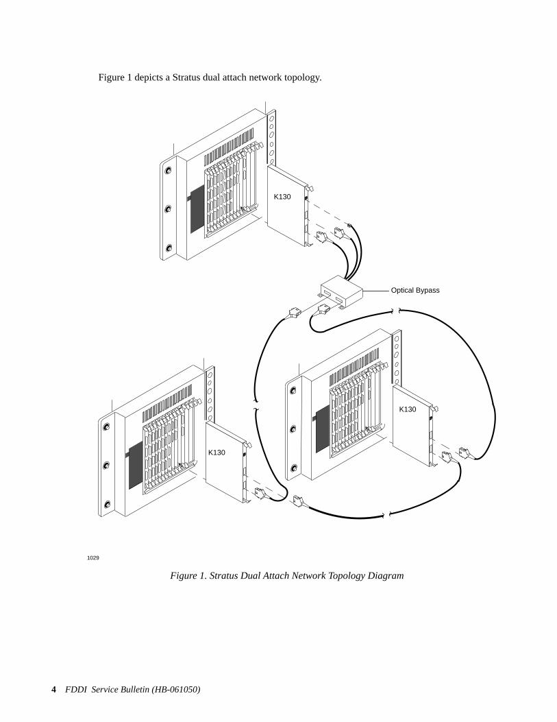
Connection to a fiber optic local area network is by way of either a fiber optic concentrator or an opti-cal bypass switch box. Regardless of which of these options is selected, it is customer-supplied and isnot supported by Stratus.
The optical bypass relay box maintains connectivity of the FDDI LAN ring in the absence of power orduring fault conditions in a network node. The bypass relay allows the light to bypass the opticalreceiver in the faulty node. In this way, the faulty node is bypassed and operation of the FDDI ring ismaintained.
A single I104 FDDI controller and K130 IOA pair provides a simplex connection to a single FDDILAN. This connection can be either dual-attached via an optical bypass switch, or single attached viaan FDDI concentrator. A dual homed configuration provides higher reliability. In addition, a secondI104/K130 IOA pair can be used to connect to the same FDDI LAN or to separate FDDI LANs.
4 FDDI Service Bulletin (HB-061050)
Figure 1 depicts a Stratus dual attach network topology.
Figure 1. Stratus Dual Attach Network Topology Diagram
1029
K130
K130
K130
Optical Bypass
FDDI Service Bulletin (HB-061050)5
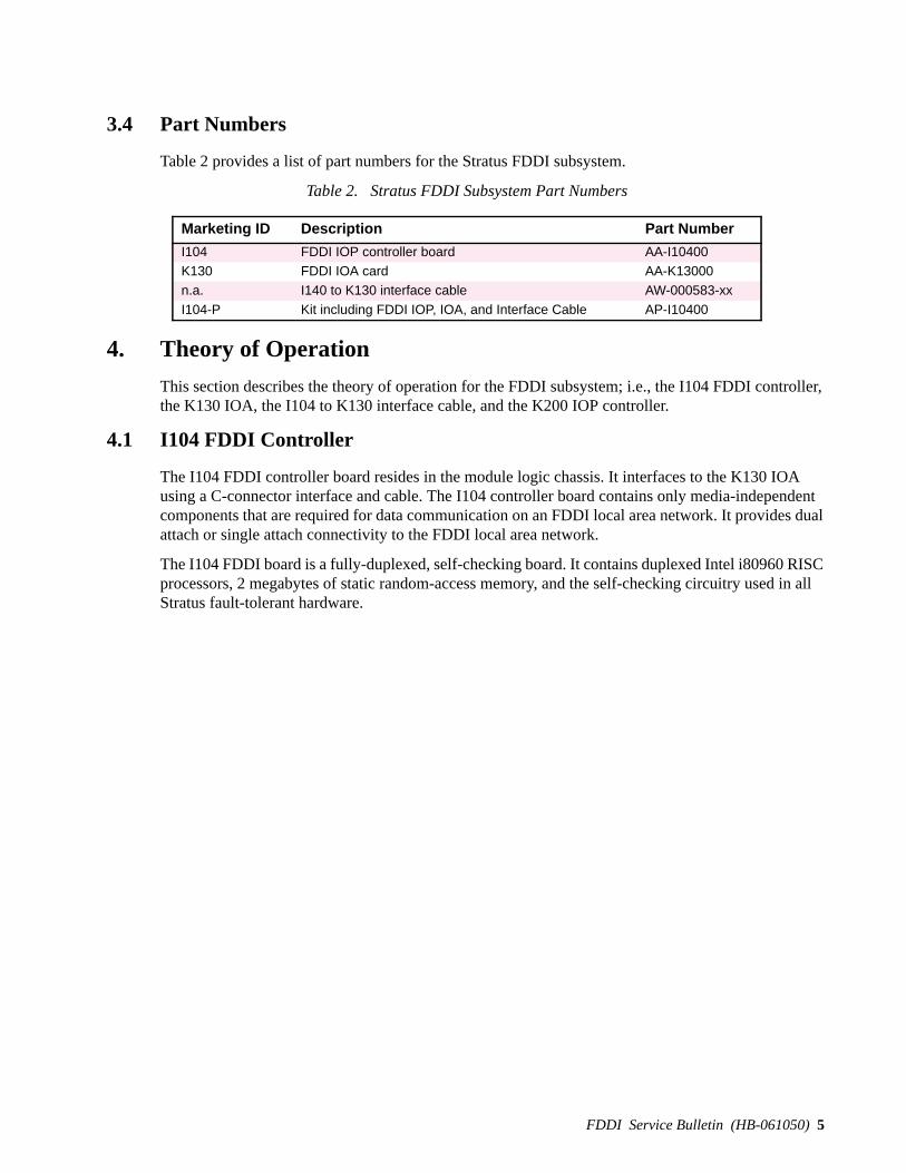
3.4 Part Numbers
Table 2 provides a list of part numbers for the Stratus FDDI subsystem.
Table 2. Stratus FDDI Subsystem Part Numbers
4. Theory of Operation
This section describes the theory of operation for the FDDI subsystem; i.e., the I104 FDDI controller,the K130 IOA, the I104 to K130 interface cable, and the K200 IOP controller.
4.1 I104 FDDI Controller
The I104 FDDI controller board resides in the module logic chassis. It interfaces to the K130 IOAusing a C-connector interface and cable. The I104 controller board contains only media-independentcomponents that are required for data communication on an FDDI local area network. It provides dualattach or single attach connectivity to the FDDI local area network.
The I104 FDDI board is a fully-duplexed, self-checking board. It contains duplexed Intel i80960 RISCprocessors, 2 megabytes of static random-access memory, and the self-checking circuitry used in allStratus fault-tolerant hardware.
Marketing ID Description Part Number
I104 FDDI IOP controller board AA-I10400K130 FDDI IOA card AA-K13000n.a. I140 to K130 interface cable AW-000583-xxI104-P Kit including FDDI IOP, IOA, and Interface Cable AP-I10400
6 FDDI Service Bulletin (HB-061050)
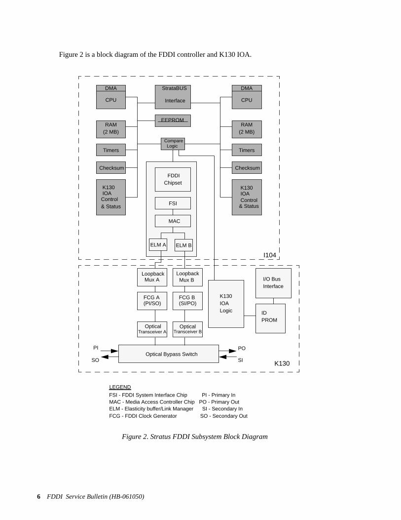
Figure 2 is a block diagram of the FDDI controller and K130 IOA.
Figure 2. Stratus FDDI Subsystem Block Diagram
DMA
RAM(2 MB)
Timers
Checksum
Control
StrataBUS
Interface
FDDIChipset
FSI
MAC
EEPROM
Compare
K130IOA
Loopback Mux A Mux B
Loopback
FCG A FCG B(PI/SO) (SI/PO)
Optical OpticalTransceiver B
& Status
Optical Bypass Switch
CPU
PO PI
SISO
LEGEND
K130IOALogic
FSI - FDDI System Interface Chip PI - Primary In
I/O BusInterface
IDPROM
DMA
CPU
RAM(2 MB)
Timers
K130IOAControl
& Status
MAC - Media Access Controller Chip PO - Primary OutELM - Elasticity buffer/Link Manager SI - Secondary InFCG - FDDI Clock Generator SO - Secondary Out
Checksum
ELM A ELM B
Transceiver A
Logic
I104
K130
FDDI Service Bulletin (HB-061050)7
4.2 K130 IOA Card
The K130 IOA is a non self-checking card that plugs into a standard IOA chassis. It is controlled bythe I104 controller board that resides in the logic chassis. The cable connection consists of a 100-con-ductor twisted pair cable. Data from the I104 flows through a loopback multiplexer, through theFDDI Clock Generator chip, into an optical transceiver module, and back again. The K130 logic sec-tion provides programmable control, status information, and interrupt functionality to the controllerboard.
The K130 IOA contains an ID PROM that is read by the K200 IOP by way of the PK bus. The K130IOA has no intelligence of its own. Both the K200 IOP and the FDDI controller are required to recog-nize the K130 IOA, so both controllers must be operational for the FDDI subsystem to work.
The K130 IOA provides the electrical to optical conversion and physical interface to the FDDI localarea network. The card provides three physical interface ports for external connections. Two of theseports correspond to port A and port B, which furnish connection to the primary and secondary rings ofthe FDDI dual-ring topology by way of either an FDDI concentrator or an optical bypass switch. Stra-tus does not supply concentrators or optical bypass switches. These are the responsibility of the cus-tomer.
The upper connector is for cable connection to the optical bypass switch box, if one is used. This con-nector transmits electrical power and control signals to the optical bypass switch box when the K130IOA is active. If the K130 IOA is connected to a concentrator, the optical bypass switch connector onthe K130 is not used.
4.3 I104 to K130 Interface Cable
The I104 to K130 interface cable (AW-000385) runs from the C-bus in the logic chassis to the K130IOA card. This cable is a 100 pin conductor shielded twisted pair bulk cable which connects to the Cinterface port for the I104 cable. Fifty of the cable signals are ground. The other fifty are data lines,control signals, and unconnected lines. The ground signals are known as the J0003 connector and theother signals are known as the J0004 connector.
4.4 K200 IOP Controller
The K200 IOP controller reads the K130 IOA card ID PROM and supplies operating voltage to thecard. Both the K200 IOP controller and the I104 FDDI controller must be in service for the FDDI sub-system to operate. However, the K200 can read the K130 IOA ID even when the FDDI controller(I104) is not online. If the K200 IOP is unable to read the K130 ID PROM, the operating system doesnot configure the I104 FDDI controller board.
8 FDDI Service Bulletin (HB-061050)
5. Installation Procedures
Installation of the FDDI subsystem consists of
• installing the K130 IOA card
• connecting the interface cable to the K130 IOA card
• installing the I104 FDDI controller board
• connecting the interface cable to the I104 FDDI controller board
Refer to the following step procedures.
CAUTION: We recommend that the system be shutdown during this procedure. If theinstallation is done while powered on, use extreme caution while installing the interfacecable.
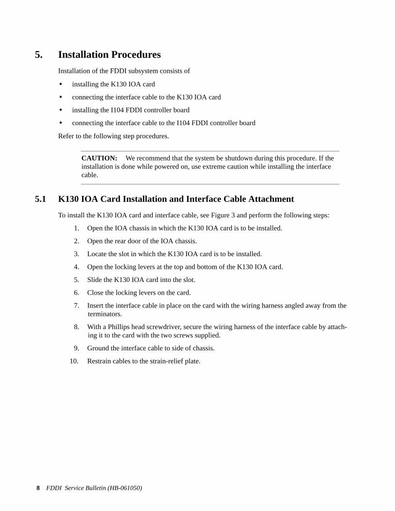
5.1 K130 IOA Card Installation and Interface Cable Attachment
To install the K130 IOA card and interface cable, see Figure 3 and perform the following steps:
1. Open the IOA chassis in which the K130 IOA card is to be installed.
2. Open the rear door of the IOA chassis.
3. Locate the slot in which the K130 IOA card is to be installed.
4. Open the locking levers at the top and bottom of the K130 IOA card.
5. Slide the K130 IOA card into the slot.
6. Close the locking levers on the card.
7. Insert the interface cable in place on the card with the wiring harness angled away from theterminators.
8. With a Phillips head screwdriver, secure the wiring harness of the interface cable by attach-ing it to the card with the two screws supplied.
9. Ground the interface cable to side of chassis.
10. Restrain cables to the strain-relief plate.

FDDI Service Bulletin (HB-061050)9
NOTE: Figure 3 also shows an exploded view (inset) of the wiring harness. Refer tothe inset only if the wiring harness has been delivered dis-assembled.
Figure 3. Securing the Interface Cable to the K130 IOA Card
1031
Grounding
Grounding Screws (2)
Interface Cable
GroundingScrews (2)
Wiring Harness
Phillips Screws (2)
Location
10 FDDI Service Bulletin (HB-061050)
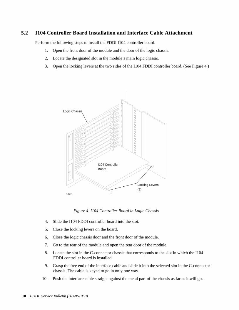
5.2 I104 Controller Board Installation and Interface Cable Attachment
Perform the following steps to install the FDDI I104 controller board.
1. Open the front door of the module and the door of the logic chassis.
2. Locate the designated slot in the module’s main logic chassis.
3. Open the locking levers at the two sides of the I104 FDDI controller board. (See Figure 4.)
Figure 4. I104 Controller Board in Logic Chassis
4. Slide the I104 FDDI controller board into the slot.
5. Close the locking levers on the board.
6. Close the logic chassis door and the front door of the module.
7. Go to the rear of the module and open the rear door of the module.
8. Locate the slot in the C-connector chassis that corresponds to the slot in which the I104FDDI controller board is installed.
9. Grasp the free end of the interface cable and slide it into the selected slot in the C-connectorchassis. The cable is keyed to go in only one way.
10. Push the interface cable straight against the metal part of the chassis as far as it will go.
1027
I104 ControllerBoard
Locking Levers
(2)
Logic Chassis
FDDI Service Bulletin (HB-061050)11
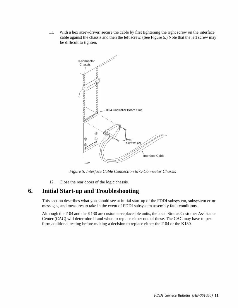
11. With a hex screwdriver, secure the cable by first tightening the right screw on the interfacecable against the chassis and then the left screw. (See Figure 5.) Note that the left screw maybe difficult to tighten.
Figure 5. Interface Cable Connection to C-Connector Chassis
12. Close the rear doors of the logic chassis.
6. Initial Start-up and Troubleshooting
This section describes what you should see at initial start-up of the FDDI subsystem, subsystem errormessages, and measures to take in the event of FDDI subsystem assembly fault conditions.
Although the I104 and the K130 are customer-replaceable units, the local Stratus Customer AssistanceCenter (CAC) will determine if and when to replace either one of these. The CAC may have to per-form additional testing before making a decision to replace either the I104 or the K130.
1030
C-connector Chassis
I104 Controller Board Slot
Hex Screws (2)
Interface Cable

12 FDDI Service Bulletin (HB-061050)
6.1 Initial Start-up
After the installation is complete, the following processes should take place.
1. K200 IOP recognition of the K130 IOA.
2. K130 FDDI IOA card self-test pass.
3. I104 FDDI controller board self-test pass.
4. I104 firmware download.
5. TCP start-up.
The following is a sample of the status message that should appear on the console screen or in the sys-tem status log after installation is complete. Failure of a message like this one to appear indicates afault condition.
date time [FTS, cpu] k130 02 00 06 IOA board all tests passed
date time [FTS, cpu11] i104 06 IOP Stratabus board all tests passed
date time [FTX, cpu0] i104 06 downloading fw (/etc/i104_fddi.coff)
date time [FTS, cpu1] i1o4 06 IOP Stratabus board all tests passed
date time [FTS,cpu1] i1004 06 fw download successful
date time [FDDI, cpu1] FDDI 6: (0) [#1] Release 1.0 - initialization complete
During the process shown above, the K130 IOA LED is first red-lighted, then the LED on both theK130 IOA and the I104 FDDI controller turn off.
NOTE: The module does not attempt to configure the I104 FDDI controller if theK200 IOP controller can not read the K130 IOA ID PROM.
6.2 Troubleshooting Checklist
In the event that other than normal status is reported in the system error log for the FDDI subsystem,first ensure that:
• the K130 cable is in place
• the interface cable is properly connected to the C-bus chassis slot for the I104 controller board.
If the cabling is in order, and the self-test indicates that the K130 IOA ID PROM has not been recog-nized by the K200 IOP controller, the K130 IOA card should be replaced. In case of other self-test fail-ures, refer to the following section on FDDI subsystem self-test sub-tests.
Note that error and status information is obtained from the console and error log.
6.3 FDDI Subsystem Self-Test Indications
Failure of the FDDI subsystem self-test results in red-lighting of the I104 FDDI controller board.However, red-lighting of the LEDs on the I104 and/or the K130 can occur in cases other than self-testfailure. Therefore, it is important to always refer to the status log messages. If the self-test passes, onlyanInitialization Complete message appears in the status log.

FDDI Service Bulletin (HB-061050)13
6.3.1 K130 IOA Broken
A broken K130 IOA results not only in failure of its self-test and red-lighting of its LED, but failure ofthe I104 self-test and red-lighting of its LED. Messages similar to the ones shown below appear in thestatus log or on the console.
date time [FTS, cpu0] k130 002 00 06 IOA board inserteddate time [FTS, cpu0] k130 02 00 06 IOA board failure: Failed Selftestdate time [FTS, cpu1] 06 Stratabus board inserteddate time [FTS, cpu1] i104 06 Stratabus board identifiedfddi_photon_unit failed subtest 0x0CPU 1: WARNING: FDDI cmd 0x2b slot 0x6 timed outdate time [FTS, cpu1] i104 06 Stratabus board failure: Board Went Broken
The hwmaint lb command for both the K130 and the I104 yieldBROKEN status.
6.3.2 I104 Broken
A broken I104 FDDI controller board results in redlighting of the board’s LED and error messagessimilar to the one shown below.
date time [FTS, cpu1] i104 21 Stratabus board failure: Board Went Broken
6.3.3 Missing Interface Cable
A missing or improperly connected AW-000583 interface cable results in error messages identical tothose when the K130 IOA is missing.
NOTE: If a loose or missing cable is reconnected after the K130 has passed its selftest, or if the K130 is inserted after the I104 has already failed its self test, the I104 self testmust be manually initiated. This is done using the FTXhwmaint break command to theI104.
CPU 1: WARNING: FDDI cmd 0x2b slot 0x6 timed outfddi_photon_unit_test failed subtest 0x0date time [FTS,cpu1] i104 06 Stratabus board failure Board Went Broken
date time [FTS,cpu0] i104 06 download: load existing fw failed rc=6date time [FTS,cpu0] i104 06 oos firmware download failed
Thehwmaint/lb command results in a broken status for the I104 FDDI controller, and a listing of theK130 IOA with no status.
4 FDDI IOA k13000 20 17295 09 FDDI Controller i10400 10216 0 0 BROKEN
The I104 FDDI controller LED is red-lighted.
6.3.4 Self-Test Failures at Initialization
If at initialization of a newly installed FDDI subsystem, photon sub-test 0, sub-test 1, or sub-test 2 ofthe self-test reports an error, both the K130 IOA and the I104 controller board should be replaced. Ifsub-test 4 or 5 of a newly installed FDDI subsystem fails, the K130 IOA alone should be replaced.

14 FDDI Service Bulletin (HB-061050)
NOTE: If sub-test 4 fails, record the error message that appears in the status log fortroubleshooting purposes.
Note that when the I104 controller does it self test, it tries to communicate to the K130. If the K130 isnot installed, an error occurs. Therefore, you should install the K130 before installing the I104.
If after initial board replacement the FDDI subsystem does not pass self-test, notify the CAC for boardreplacement strategy.
7. Removal and Replacement
This section describes the removal and replacement procedures for the I104 controller board, the K130IOA card, and the AW-000538 I104 to K130 interface cable.
7.1 I104 FDDI Controller Board Removal
1. Locate the slot number of the failed board.
2. Labels that show the board slot numbers are located on both sides of the chassis. The whiteboxes display even numbers and the black boxes display odd numbers. Similarly, the evennumbered slots have white board guides and the odd numbered slots have black boardguides.
3. Release the locking levers on the failed board. (See Figure 4.)
4. Slide the board out of the cabinet.
7.2 K130 IOA Card Removal
1. Unlock and open the cabinet’s rear door.
2. Disconnect the cables from the failed IOA.
3. Extend the ejector lever on the failed IOA and remove it from the system. (See Figure 1.)
7.3 Interface Cable Removal
The following is the procedure for removing the I104 to K130 interface cable.
1. Open the rear door of the logic chassis.
2. With a hex screwdriver, remove the two screws that secure the interface cable to the C-busconnector slot. (See Figure 5.)
3. Catch the cable as it dislodges from the C-bus slot.
4. Open the rear door of the IOA chassis that contains the K130 card.
5. Loosen and remove the Phillips screws at the top and bottom of the keyed cable bar. (SeeFigure 3.)
6. Catch the cable as it releases from the cable bar.

We value your comments...Our goal is to continuously improve the quality of our documentation. You can help us achieve this goal by takinga few minutes to complete this survey.
Please rate the quality of this manual in each of the following areas.
Strongly StronglyAgree Agree Neutral Disagree Disagree
Technical AccuracyThe information is accurate.CompletenessThe information is complete.ClarityThe information is easy to understand.OrganizationThe information is easy to find.FiguresThe figures are clear and useful.ExamplesThe examples are clear and useful.IndexThe topics lead to the information that you need.Physical AppearanceThe format of the manual enhances readability.EffectivenessThe manual helped you to perform your job.
What did you like most about this manual? _____________________________________________________
_______________________________________________________________________________________
_______________________________________________________________________________________
What did you like least about this manual? _____________________________________________________
_______________________________________________________________________________________
_______________________________________________________________________________________
Is there any information that you would like to have added to this manual? If so, where would it be most helpful?
New information that you would like to have added Location
____________________________________________________ ____________________________
____________________________________________________ ____________________________
____________________________________________________ ____________________________
Would you like to see more examples in this manual? If so, where would they be most helpful?
New examples that you would like to have added Location
____________________________________________________ ____________________________
____________________________________________________ ____________________________
Did you find errors in this manual? If so, please note the problem(s) and the location in the manual.
Any inaccuracies that you found in this manual Location (page/paragraph)
____________________________________________________ ____________________________
____________________________________________________ ____________________________
Fold
Fold
Cut
alo
ng d
otte
d lin
e.
FDDI Service Bulletin (HB-061050) User Survey
6
5
4
3
2
1
________________________________________________________________________________
Do you have any other comments or suggestions? __________________________________________________
__________________________________________________________________________________________
__________________________________________________________________________________________
Would you be willing to talk to us about your comments?
Please provide your name, the name of your company, and your phone number.
____________________________________________________________________________________________
You may send this form to HQSC Publications through interoffice mail (M2-1-CAC), U.S. Mail, or FAX it to(508) 481-5635.
Thank you for your help.
BUSINESS REPLY MAIL FIRST CLASS MAIL PERMIT NO. 86 MARLBORO, MA
Postage will be paid by addressee:
ATTN: HQSC Publications M2-1-CACStratus Computer, Inc.55 Fairbanks BoulevardMarlboro, MA, 01752-9899
NO POSTAGENECESSARY IF MAILED
IN THEUNITED STATES
55 Fairbanks BoulevardMarlboro, MA 01752
Fold
Fold
Cut along dotted line.
HB-061050 User Survey7
8


Stratus Computer, Inc.55 Fairbanks Boulevard HB-061070Marlboro, MA 01752-1298 April, 1995