
A Strap and Pole - Magic Christmas · A Strap and Pole Walter Monkhouse Walter@MagicChristmas....
20
A Strap and Pole Walter Monkhouse Walter@MagicChristmas. Magic Christmas Alexandria, La. ASAP Sr Two Stage
Transcript of A Strap and Pole - Magic Christmas · A Strap and Pole Walter Monkhouse Walter@MagicChristmas....
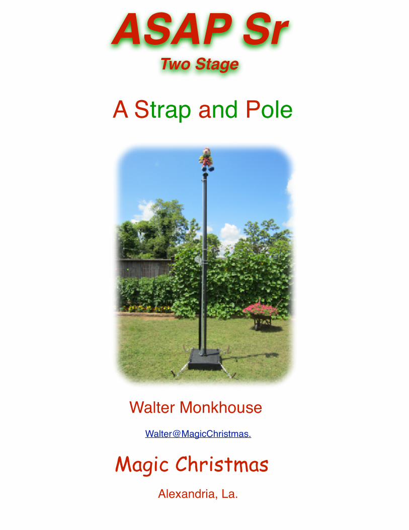
A Strap and Pole
Walter MonkhouseWalter@MagicChristmas.
Magic ChristmasAlexandria, La.
ASAP Sr Two Stage
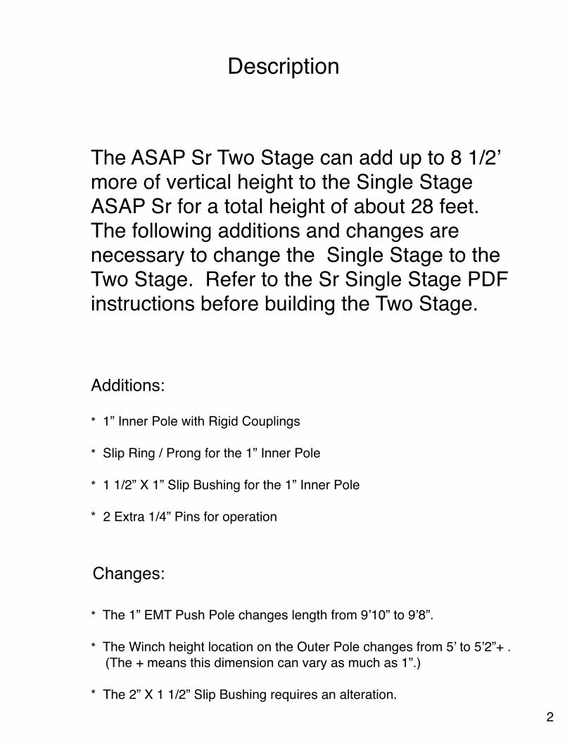
Description
The ASAP Sr Two Stage can add up to 8 1/2’ more of vertical height to the Single Stage ASAP Sr for a total height of about 28 feet. The following additions and changes are necessary to change the Single Stage to the Two Stage. Refer to the Sr Single Stage PDF instructions before building the Two Stage.
Additions:
* 1” Inner Pole with Rigid Couplings
* Slip Ring / Prong for the 1” Inner Pole
* 1 1/2” X 1” Slip Bushing for the 1” Inner Pole
* 2 Extra 1/4” Pins for operation
Changes:
* The 1” EMT Push Pole changes length from 9’10” to 9’8”.
* The Winch height location on the Outer Pole changes from 5’ to 5’2”+ . (The + means this dimension can vary as much as 1”.)
* The 2” X 1 1/2” Slip Bushing requires an alteration.2
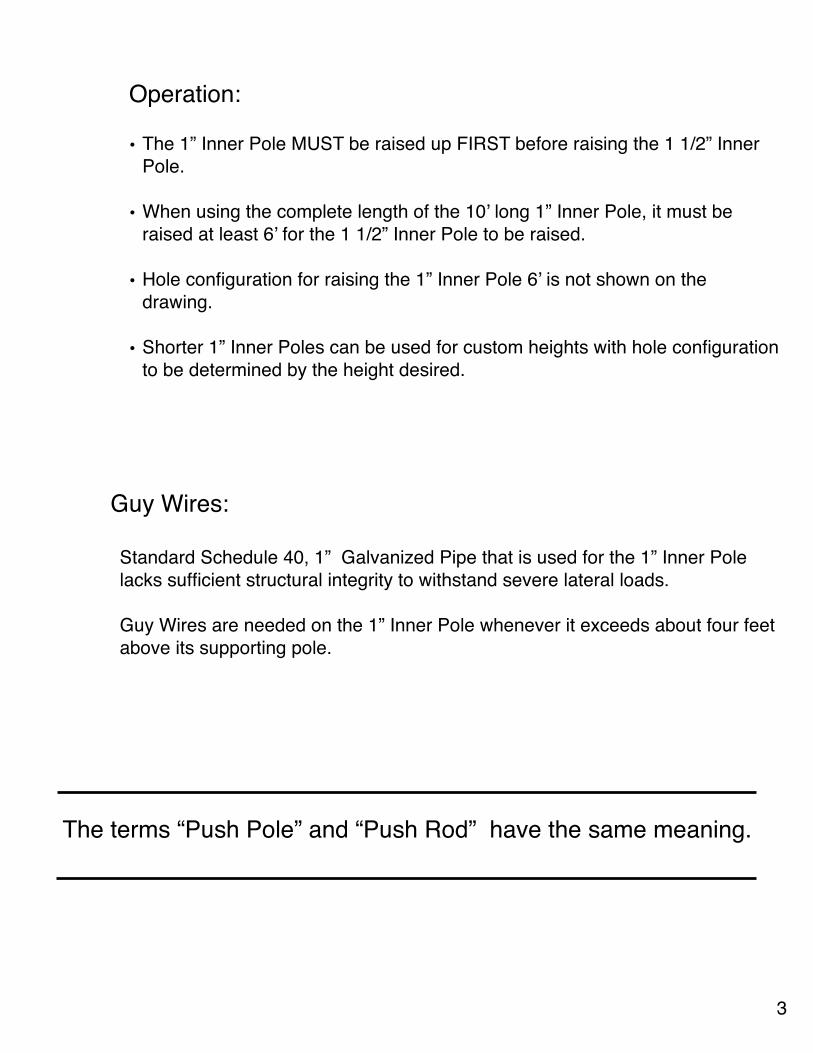
Operation:
• The 1” Inner Pole MUST be raised up FIRST before raising the 1 1/2” Inner Pole.
• When using the complete length of the 10’ long 1” Inner Pole, it must be raised at least 6’ for the 1 1/2” Inner Pole to be raised.
• Hole configuration for raising the 1” Inner Pole 6’ is not shown on the drawing.
• Shorter 1” Inner Poles can be used for custom heights with hole configuration to be determined by the height desired.
Guy Wires:
Standard Schedule 40, 1” Galvanized Pipe that is used for the 1” Inner Pole lacks sufficient structural integrity to withstand severe lateral loads.
Guy Wires are needed on the 1” Inner Pole whenever it exceeds about four feet above its supporting pole.
3
The terms “Push Pole” and “Push Rod” have the same meaning.
ASAP Sr - Two Stage
1” EMTPush Pole
9’ 8”
2” X 1 1/2” Slip Bushing
2” Rigid Coupling
Banding Clamp
WinchBottom ClampGoes Here
2” Outer Pole Rigid Elec Conduit
Portable Hole
5’ 2” +
1” PVC (Grey) CouplingUpper Rod Guide
1 1/2” Inner PoleRigid Elec Conduit
2” Centers
1/4” Holes
1/4” Hole
Inner PoleCentralizer
1’6”
4’3”
4’3”
1 1/2” RigidCoupling
1 1/2” X 1”Slip Bushing
Slip Ring / Prong
1” Inner PoleGalvanized Pipe
1 5/8” Centers
1/4” Holes
1/4” Hole
1’6”
4’3”
4’3”
1” Rigid Coupling
1” Rigid Coupling
Slip Ring / Prong
Pin
1/4” X 4” Bolt4 Required
Poles Needed:1 - 2” X 10’ (9’11”) Rigid Elec Conduit. Comes with a 2” Rigid Coupling.1 - 1 1/2” X 10’ (9’11”) Rigid Elec Conduit. Comes with a 1 1/2” Rigid Coupling.1 - 1” X 10’ Galvanized Pipe1 - 1” X 10’ EMT
Winch
Diagram and Measurements
4
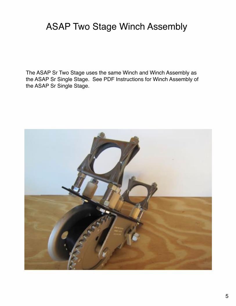
ASAP Two Stage Winch Assembly
The ASAP Sr Two Stage uses the same Winch and Winch Assembly as the ASAP Sr Single Stage. See PDF Instructions for Winch Assembly of the ASAP Sr Single Stage.
5
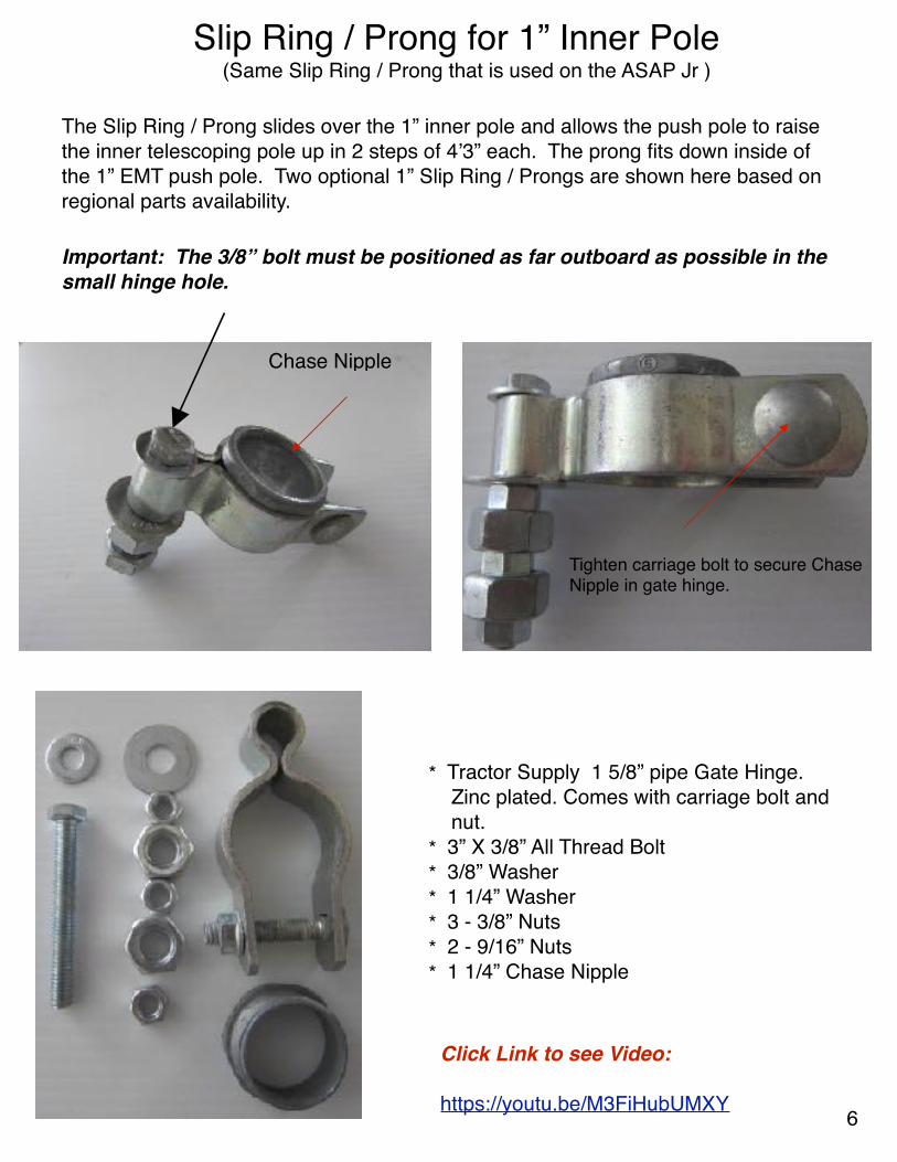
Slip Ring / Prong for 1” Inner Pole (Same Slip Ring / Prong that is used on the ASAP Jr )
The Slip Ring / Prong slides over the 1” inner pole and allows the push pole to raise the inner telescoping pole up in 2 steps of 4’3” each. The prong fits down inside of the 1” EMT push pole. Two optional 1” Slip Ring / Prongs are shown here based on regional parts availability.
* Tractor Supply 1 5/8” pipe Gate Hinge. Zinc plated. Comes with carriage bolt and nut.* 3” X 3/8” All Thread Bolt* 3/8” Washer* 1 1/4” Washer* 3 - 3/8” Nuts* 2 - 9/16” Nuts* 1 1/4” Chase Nipple
Click Link to see Video:
https://youtu.be/M3FiHubUMXY
Chase Nipple
Tighten carriage bolt to secure Chase Nipple in gate hinge.
Important: The 3/8” bolt must be positioned as far outboard as possible in the small hinge hole.
6
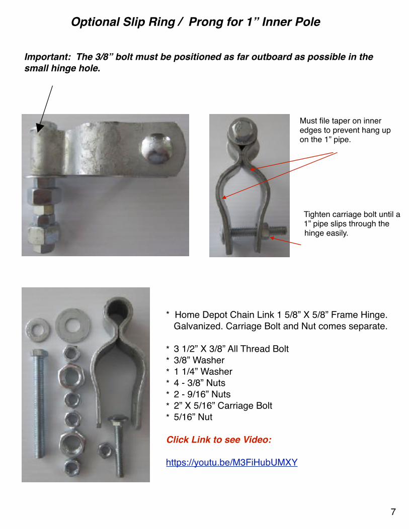
Optional Slip Ring / Prong for 1” Inner Pole
Must file taper on inner edges to prevent hang up on the 1” pipe.
Tighten carriage bolt until a 1” pipe slips through the hinge easily.
* Home Depot Chain Link 1 5/8” X 5/8” Frame Hinge. Galvanized. Carriage Bolt and Nut comes separate.
* 3 1/2” X 3/8” All Thread Bolt* 3/8” Washer* 1 1/4” Washer* 4 - 3/8” Nuts* 2 - 9/16” Nuts* 2” X 5/16” Carriage Bolt* 5/16” Nut
Click Link to see Video:
https://youtu.be/M3FiHubUMXY
Important: The 3/8” bolt must be positioned as far outboard as possible in the small hinge hole.
7

8
Slip Ring / Prong for 1 1/2” Inner Pole (Same Slip Ring / Prong as used for the ASAP Sr Single Stage)
The Slip Ring / Prong slides over the 1 1/2” inner pole and allows the push pole to raise the inner telescoping pole up in steps of 4’3” each. The prong fits down inside of the 1” EMT push pole.
2” Pipe Gate Hinge Zinc Coated National Hardware N275-495 299BC(Google National Hardware for supply outlets such as Tractor Supply.)
*1/2” X 4” All Thread Bolt (Home Depot)*2 - 1/2” Washers (AGB) (Home Depot)*3 - 1/2” Nuts (Home Depot)*2 - 9/16” Nuts (Ace Hardware)
Place the 1/2” bolt snugly outboard in the hole before tightening the 3/8” nut.
Add 9/16” nut. This nut does not fit the 1/2” bolt but loosely screws onto it.
Then add the following nuts in this order:3/8” , 9/16”, 3/8”.
Caution: There are other Pipe Gate Hinges available but most do not have the structural integrity as the one listed above.
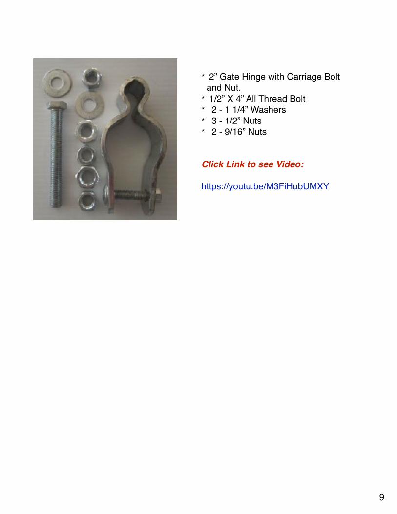
* 2” Gate Hinge with Carriage Bolt and Nut.
* 1/2” X 4” All Thread Bolt* 2 - 1 1/4” Washers* 3 - 1/2” Nuts* 2 - 9/16” Nuts
Click Link to see Video:
https://youtu.be/M3FiHubUMXY
9
X
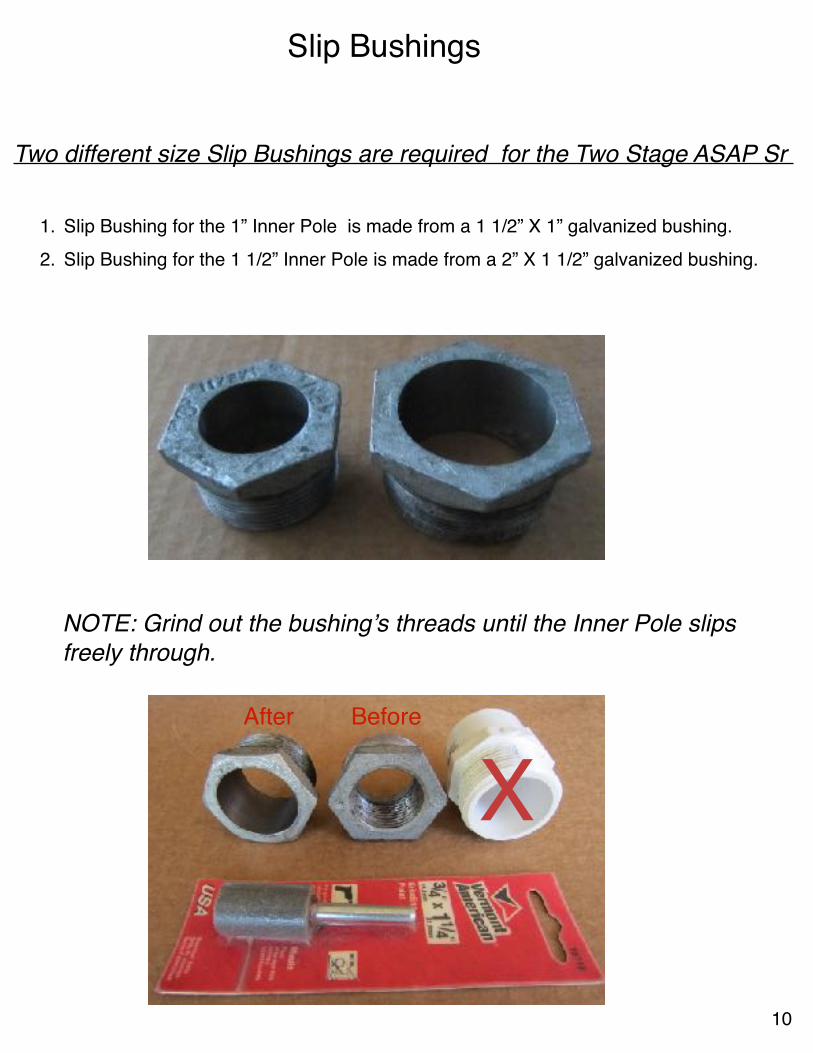
Slip Bushings
Two different size Slip Bushings are required for the Two Stage ASAP Sr
1. Slip Bushing for the 1” Inner Pole is made from a 1 1/2” X 1” galvanized bushing. 2. Slip Bushing for the 1 1/2” Inner Pole is made from a 2” X 1 1/2” galvanized bushing.
NOTE: Grind out the bushing’s threads until the Inner Pole slips freely through.
BeforeAfter
10
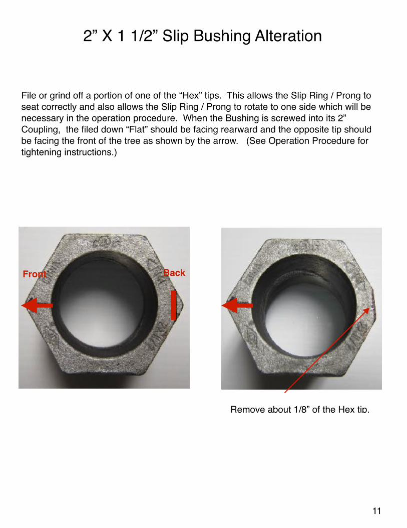
2” X 1 1/2” Slip Bushing Alteration
Front Back
Remove about 1/8” of the Hex tip.
File or grind off a portion of one of the “Hex” tips. This allows the Slip Ring / Prong to seat correctly and also allows the Slip Ring / Prong to rotate to one side which will be necessary in the operation procedure. When the Bushing is screwed into its 2” Coupling, the filed down “Flat” should be facing rearward and the opposite tip should be facing the front of the tree as shown by the arrow. (See Operation Procedure for tightening instructions.)
11

Other Parts
1″ EMT Guide
1 - 1″ Elec PVC coupling (Grey)1 - 3 1/2″ dia Hose Clamp (Home Depot)
4 Pins required for 28’ high operation.Use 1/4” X 4” or 4 1/2” Bolts.File the tips to a point for ease of insertion into pipe holes.
Pins
12
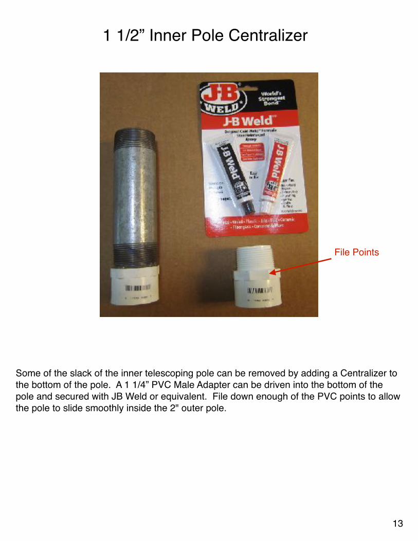
1 1/2” Inner Pole Centralizer
Some of the slack of the inner telescoping pole can be removed by adding a Centralizer to the bottom of the pole. A 1 1/4” PVC Male Adapter can be driven into the bottom of the pole and secured with JB Weld or equivalent. File down enough of the PVC points to allow the pole to slide smoothly inside the 2" outer pole.
File Points
13
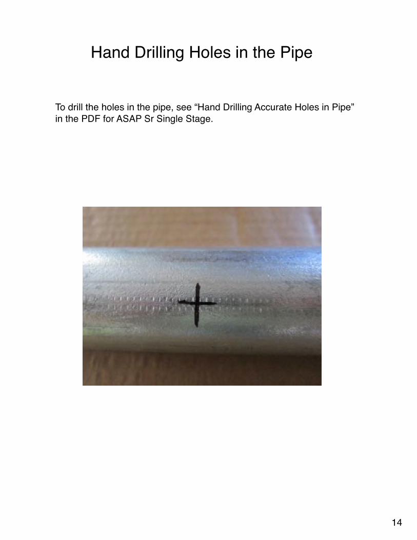
Hand Drilling Holes in the Pipe
To drill the holes in the pipe, see “Hand Drilling Accurate Holes in Pipe” in the PDF for ASAP Sr Single Stage.
14
Set Up Procedure for ASAP Sr Two Stage
1. With the Portable Hole flat on the ground and 2” Outer Pole held straight up in vertical position, screw the outer pole tightly into Portable Hole. Use Teflon Tape on threads. Use a pipe wrench for tightening. Attach Winch to 2” Outer Pole on the back of the pole.
2. Lay the 2” Outer Pole and Winch down onto a support 1’ to 2’ high.
3. Screw 2” Rigid Coupling onto top of 2” Outer Pole and tighten.
4. Install upper Push Rod Guide onto 2” Outer Pole just under 2” Coupling.
5. Slide 1” EMT Push Rod through Upper Rod Guide and through Winch space all the way to Portable Hole base.
6. Slide 1 1/2” Inner Pole into 2” Outer Pole so that the two drilled holes are showing. Rotate the 1 1/2” Inner Pole so that the drilled holes are sideways and parallel to the ground. This insures the pins will be able to be inserted sideways. Place a mark on the top side of the Inner Pole near the threads.
7. Slide 2” X 1 1/2” Slip Bushing over the 1 1/2” Outer Pole. Be sure when tightening , the filed off Hex Tip of the Slip Bushing is facing upward when finished tightening. Use Teflon Tape on the threads to aid in this.
8. Slide Slip Ring / Prong onto the 1 1/2” Inner pole. Be sure the Slip Ring / Prong seats flatly on the Slip Bushing and can rotate about 1/4 turn to one side.
9. Screw 1 1/2” Rigid Coupling onto the 1 1/2” Inner Pole and tighten. Mark the top side of coupling with the drilled holes still parallel to ground.
10. Screw 1” Rigid Coupling to bottom of 1” Inner Pole and tighten. Slide 1” Inner Pole into the 1 1/2” Inner Pole.
11. Slide 1 1/2” X 1” Slip Bushing onto the 1” Inner Pole and screw the Slip Bushing into the 1 1/2” Rigid Coupling of the 1 1/2” Pole and tighten. Mark the topside of the 1” Inner Pole with the Pin holes to the side and parallel with the ground.
12. Slide Slip Ring / Prong onto the 1” Inner Pole.
13. Screw 1” Rigid Coupling onto 1” Inner Pole and tighten. Mark top side of Coupling with the drilled holes to the side and parallel to the ground.
14. IMPORTANT! Slide all of the above components together so they are stacked next to and against each other. CAUTION! Watch out for pinching fingers and hand.
15. Stand up the entire assembly.
16. At this point in normal use the Portable Hole would be correctly tethered to the ground.
15
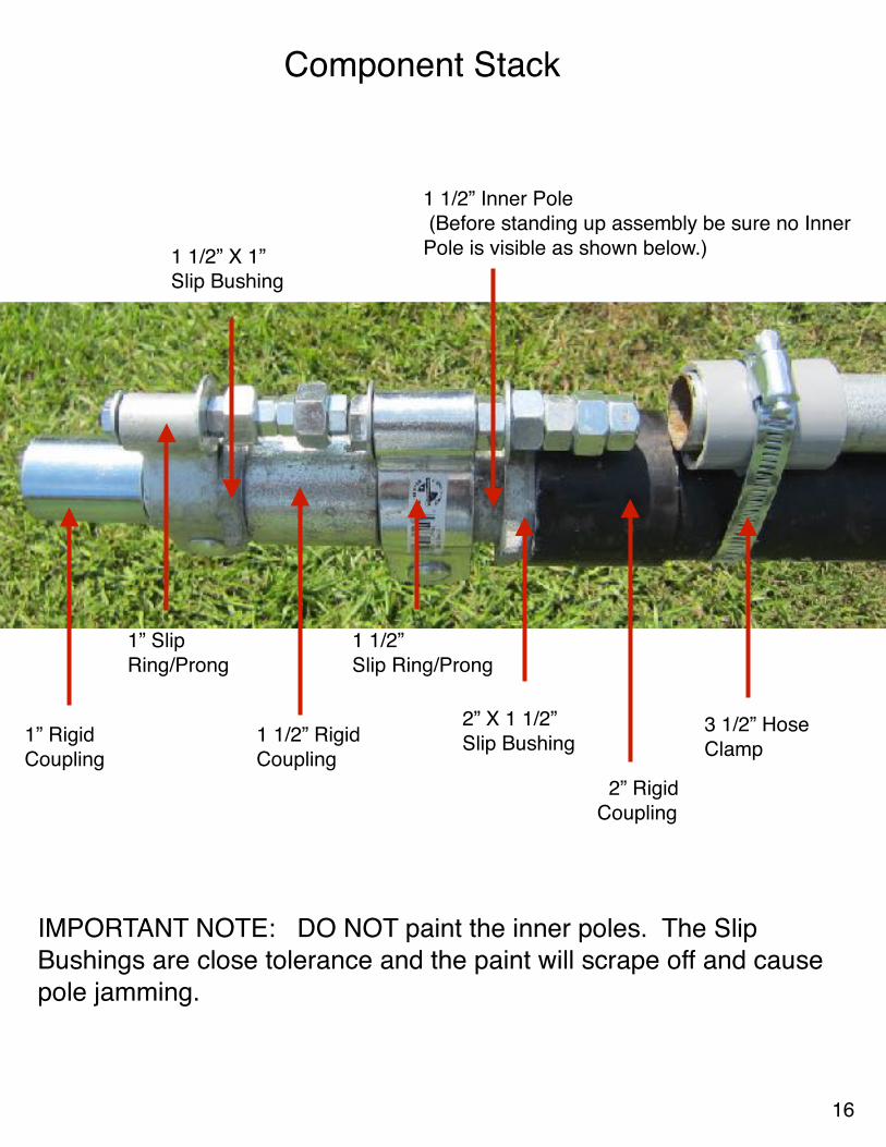
2” RigidCoupling
2” X 1 1/2” Slip Bushing
1 1/2” Inner Pole (Before standing up assembly be sure no Inner Pole is visible as shown below.)
1 1/2” Slip Ring/Prong
1 1/2” RigidCoupling
1 1/2” X 1” Slip Bushing
1” SlipRing/Prong
1” RigidCoupling
3 1/2” HoseClamp
IMPORTANT NOTE: DO NOT paint the inner poles. The Slip Bushings are close tolerance and the paint will scrape off and cause pole jamming.
Component Stack
16
Operation Procedure
1. The telescoping pole start at about 10’ high. A 6’ step ladder is needed to reach the pin insertion points.
2. CAUTION! The Winch crank handle is located at head level. Stand to the side to operate the winch.
3. Pull enough strap from the winch to place the hook into the bottom of the Push Pole.
4. The 1” Inner Pole must be raised first. 5. Rotate the Slip Ring / Prong of the 1 1/2” Inner Pole to one side so that the Push
Pole can be raised up to engage the Sling Ring / Prong of the 1” Inner Pole. 6. Be sure the Prong of the 1” Slip Ring / Prong is completely seated inside of the 1”
Push Pole.7. Raise the 1” Inner Pole 4’3” until two holes are visible. 8. Place a Pin into the bottom hole.9. Lower the Slip Ring / Prong down onto the inserted pin. 10. Insert a Pin into the hole above the Slip Ring. 11. Raise the 1” Inner Pole up a few inches and pull the Pin that was inserted into the
bottom hole. 12.Raise the 1” Inner Pole up another 4’3” until the hole near the bottom is visible. 13. Insert a Pin in the single visible hole and lower the Push Pole until it is even with
the top of the Push Pole Guide. 14.Rotate the 1 1/2” Slip Ring / Prong into place so that the Push Pole can engage it.
It may be necessary to tap the 1 1/2” Slip Ring / Prong into place with a rubber mallet. When rotating the Slip Ring / Prong be sure the 1 1/2” Pole does not move.
15. Raise the Push Pole until the Prong of the 1 1/2” Slip Ring is completely seated inside of the Push Pole.
16.Raise the 1 1/2” Inner Pole 4’3” until 2 holes are visible. 17.Perform the same operation as for the 1” Inner Pole to raise the 1 1/2” Inner Pole
up another 4’3”. 18.Reverse the procedure to lower the poles. 19.Raise and lower the pole several times to become familiar with operation.
17

To Limit Rotation of Inner Poles:
After a pole is completely raised insert a bolt instead of a Pin. Put a washer on the bolt, slide the bolt through the hole in the pole and add another washer and nut. When the nut is tightened the washers will snug up against the “flats” of the Slip Bushing and limit the pole rotation.
18

Contact Info:
Walter Monkhouse
Email: [email protected]
Phone: 318-487-0736
Website: www.MagicChristmas.org
Facebook: https://www.facebook.com/MagicChristmas
ASAP Video: https://www.youtube.com/watch?v=P8XRpqi3dvU
19
Disclaimer
This Document explains how I built the ASAP Pole for my own personal use.Anyone building or using the ASAP pole from these plans and information does so at their own discretion and liability.
Walter B. Monkhouse August 2, 2017
20