A standard for real-time smart transducer interface
12
A standard for real-time smart transducer interface Wilfried Elmenreich * , Wolfgang Haidinger, Hermann Kopetz, Thomas Losert, Roman Obermaisser, Michael Paulitsch, Philipp Peti Institut fu ¨r Technische Informatik, Technische Universita ¨t Wien, Treitlstrasse 1-3/182-1, Vienna, Austria Received 13 May 2005; received in revised form 6 September 2005; accepted 6 September 2005 Available online 30 September 2005 Abstract In order to handle the inherent complexity of the multitude of available different transducer components, a generic interface approach is necessary. Such a universal smart transducer interface should provide precisely defined interfaces between smart transducers and their users, which are simple and precisely specified within the value domain and the temporal domain. The Object Management Group adopted a smart transducer interface standard that incorporates (i) real-time characteristics and functionalities for the smart transducer network (ii) online diagnostic service capability (iii) support for start-up and dynamic configuration (iv) a uniform naming and addressing scheme for all relevant data in the smart transducer system (v) a generic interface that enables the smart transducer system to interact with other systems via CORBA. This paper describes the main concepts and implementation experiences of this smart transducer interface. The approach integrates a time-triggered communication protocol with an appropriate access scheme, the so-called interface file system. This interface file system provides a unique naming and addressing scheme enabling access to internal transducer data via a CORBA gateway. D 2005 Elsevier B.V. All rights reserved. Keywords: Fieldbus systems; Real-time communication; Time-triggered systems; Smart transducers 1. Introduction The decreasing cost of computing power enables decentralization of data processing by providing com- putational intelligence close to transducers (sensors and actuators). This enables data abstraction necessary for an abstract interface definition. Such an interface definition comprises a major element in software engineering for embedded systems avoiding an emer- ging crisis in embedded systems design due to the increasing number of different transducers in current embedded systems. In embedded system applications with dramatically increasing numbers of transducers, as it is the case in the automotive market, which is marked by an ad-hoc 0920-5489/$ - see front matter D 2005 Elsevier B.V. All rights reserved. doi:10.1016/j.csi.2005.09.001 * Corresponding author. E-mail addresses: [email protected] (W. Elmenreich), [email protected] (W. Haidinger), [email protected] (H. Kopetz), [email protected] (T. Losert), [email protected] (R. Obermaisser), [email protected] (M. Paulitsch), [email protected] (P. Peti). Computer Standards & Interfaces 28 (2006) 613 – 624 www.elsevier.com/locate/csi
-
Upload
wilfried-elmenreich -
Category
Documents
-
view
213 -
download
0
Transcript of A standard for real-time smart transducer interface

www.elsevier.com/locate/csi
Computer Standards & Interf
A standard for real-time smart transducer interface
Wilfried Elmenreich *, Wolfgang Haidinger, Hermann Kopetz, Thomas Losert,
Roman Obermaisser, Michael Paulitsch, Philipp Peti
Institut fur Technische Informatik, Technische Universitat Wien, Treitlstrasse 1-3/182-1, Vienna, Austria
Received 13 May 2005; received in revised form 6 September 2005; accepted 6 September 2005
Available online 30 September 2005
Abstract
In order to handle the inherent complexity of the multitude of available different transducer components, a generic interface
approach is necessary. Such a universal smart transducer interface should provide precisely defined interfaces between smart
transducers and their users, which are simple and precisely specified within the value domain and the temporal domain.
The Object Management Group adopted a smart transducer interface standard that incorporates (i) real-time characteristics
and functionalities for the smart transducer network (ii) online diagnostic service capability (iii) support for start-up and
dynamic configuration (iv) a uniform naming and addressing scheme for all relevant data in the smart transducer system (v) a
generic interface that enables the smart transducer system to interact with other systems via CORBA.
This paper describes the main concepts and implementation experiences of this smart transducer interface. The approach
integrates a time-triggered communication protocol with an appropriate access scheme, the so-called interface file system. This
interface file system provides a unique naming and addressing scheme enabling access to internal transducer data via a CORBA
gateway.
D 2005 Elsevier B.V. All rights reserved.
Keywords: Fieldbus systems; Real-time communication; Time-triggered systems; Smart transducers
1. Introduction
The decreasing cost of computing power enables
decentralization of data processing by providing com-
0920-5489/$ - see front matter D 2005 Elsevier B.V. All rights reserved.
doi:10.1016/j.csi.2005.09.001
* Corresponding author.
E-mail addresses: [email protected]
(W. Elmenreich), [email protected] (W. Haidinger),
[email protected] (H. Kopetz), [email protected]
(T. Losert), [email protected] (R. Obermaisser),
[email protected] (M. Paulitsch), [email protected]
(P. Peti).
putational intelligence close to transducers (sensors
and actuators). This enables data abstraction necessary
for an abstract interface definition. Such an interface
definition comprises a major element in software
engineering for embedded systems avoiding an emer-
ging crisis in embedded systems design due to the
increasing number of different transducers in current
embedded systems.
In embedded system applications with dramatically
increasing numbers of transducers, as it is the case in
the automotive market, which is marked by an ad-hoc
aces 28 (2006) 613–624

W. Elmenreich et al. / Computer Standards & Interfaces 28 (2006) 613–624614
approach of system engineering with a multitude of
different components (and different interface defini-
tions), a generic approach can significantly reduce the
development costs.
Some interface descriptions for embedded compo-
nents exist already and are used extensively (e.g.,
CAN Kingdom [1], OSEK [2], and IEEE 1451.2
[3]), yet do address a precise interface description in
the time and space domain and standardization is
often supplier specific. System engineering of a
CAN-based approach, e.g., can be inherently difficult
and lead to unintended system behavior for certain
CAN implementation (see e.g. Meschi et al. [4]).
In this paper we present a generic approach for the
organization of transducers and communication
between transducers that provides features in terms of
real-time guarantees, complexity management, and
maintainability. Smart transducers integrate an analog
or digital sensor or actuator element and a local micro-
controller that contains the interface circuitry, a proces-
sor, memory, and a network controller within a single
unit. A smart transducer transforms the raw sensor
signal to a standardized digital representation, checks
and calibrates the signal, and transmits this digital
signal via a standardized communication protocol to
its users [5]. The possibility of reducing complexity
using the concept of a smart transducer is of paramount
benefit as basic element of a system engineering
approach in embedded networks, which cannot be
valued highly enough, though initially overlooked
due to the current supply chain structure.
In addition to providing a building block for a
successful management of a smooth software engi-
neering process of embedded systems, a precise inter-
face definition facilitates communication system
design. We present a communication system with
guaranteed timeliness and a deterministic description
of communication traffic. Such a description of a
distributed transducer system design can alleviate
system development. Time partitioning mechanisms
on a communication bus decrease the wiring loom
complexity and provide additional benefits such as
reduced weight, reduced wiring costs, and improve
the system reliability due to the decreased number of
parts with high failure rates such as connectors.
In December 2000 the Object Management Group
(OMG) called for a proposal (RFP) of a smart trans-
ducer interface (STI) that satisfies the following
needs: (i) real-time characteristics and functionalities
for the smart transducer network (ii) online diagnostic
service capability (iii) support for start-up and
dynamic configuration (iv) a uniform naming and
addressing scheme for all relevant data in the smart
transducer system (v) a generic interface that enables
the smart transducer system to interact with other
systems via a CORBA (Common Object Request
Broker Architecture) gateway, and (vi) the support
of communication interfaces available on current
low-cost microcontrollers, e.g., UART ports. In
response to this RFP, a time-triggered communication
architecture with a well-defined interface to a CORBA
environment has been submitted jointly by three com-
panies with support of the Vienna University of Tech-
nology. This proposed STI standard has been adopted
and published by the OMG as a world-wide standard
in 2003 [6]. In this paper we describe this approach
and present two case study implementations.
2. Related work
A smart transducer interface should conform to a
world-wide standard. Such a standard for real-time
communication systems has been long sought, but
vendors of existing were reluctant to support such a
single common standard in fear of losing some of their
competitive advantages.
In the field of fieldbus communication, several dif-
ferent fieldbus solutions have been developed and
promoted. Some of these existing solutions have been
combined and standardized. The European CENELEC
standard was created by including all national stan-
dards into the standard parts EN 50170 (general pur-
pose), EN 50254 (high efficiency), and EN 50325
(based on Controller Area Network (CAN)). In 1994,
the two large fieldbus groups ISP (Interoperable Sys-
tems Project supported by Fisher–Rosemount, Sie-
mens, Yokogawa, and others) and the WorldFIP (Flux
Information Processus or Factory Instrumentation Pro-
tocol, supported by Honeywell, Bailey, and others)
joined to form the Fieldbus Foundation (FF). It is the
stated objective of the FF to develop a single interoper-
able fieldbus standard in cooperation with the Interna-
tional Electrotechnical Commission (IEC) and the
Instrumentation Society of America (ISA). The IEC
worked out the IEC 61158 standard, which is based on
W. Elmenreich et al. / Computer Standards & Interfaces 28 (2006) 613–624 615
eight existing fieldbus solutions, among them Founda-
tion Fieldbus, Profibus, and WorldFIP. The IEC and
CENELEC standards have the great disadvantage
that they still keep a diversity of very different solutions
[7].
Standards for smart transducers have been devel-
oped apart from the fieldbus standardization efforts.
The IEEE 1451.2 standard [3] deals with the specifica-
tion of interfaces for smart transducers. This standard
defines electronic data sheets to describe the hardware
interface and communication protocols of the smart
transducer interface model. The IEEE 1451 standard
includes an adequate naming/addressing scheme and
supports the configuration of large transducer systems,
but it lacks the explicit specification of real-time com-
munication among the smart transducers.
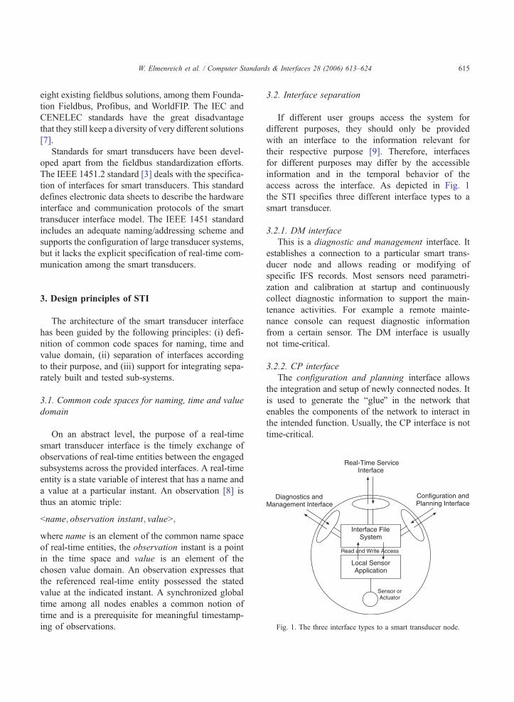
Local SensorApplication
Sensor orActuator
Read and Write Access
Interface FileSystem
Real-Time ServiceInterface
Configuration andPlanning Interface
Diagnostics andManagement Interface
Fig. 1. The three interface types to a smart transducer node.
3. Design principles of STI
The architecture of the smart transducer interface
has been guided by the following principles: (i) defi-
nition of common code spaces for naming, time and
value domain, (ii) separation of interfaces according
to their purpose, and (iii) support for integrating sepa-
rately built and tested sub-systems.
3.1. Common code spaces for naming, time and value
domain
On an abstract level, the purpose of a real-time
smart transducer interface is the timely exchange of
observations of real-time entities between the engaged
subsystems across the provided interfaces. A real-time
entity is a state variable of interest that has a name and
a value at a particular instant. An observation [8] is
thus an atomic triple:
bname; observation instant; valueN;
where name is an element of the common name space
of real-time entities, the observation instant is a point
in the time space and value is an element of the
chosen value domain. An observation expresses that
the referenced real-time entity possessed the stated
value at the indicated instant. A synchronized global
time among all nodes enables a common notion of
time and is a prerequisite for meaningful timestamp-
ing of observations.
3.2. Interface separation
If different user groups access the system for
different purposes, they should only be provided
with an interface to the information relevant for
their respective purpose [9]. Therefore, interfaces
for different purposes may differ by the accessible
information and in the temporal behavior of the
access across the interface. As depicted in Fig. 1
the STI specifies three different interface types to a
smart transducer.
3.2.1. DM interface
This is a diagnostic and management interface. It
establishes a connection to a particular smart trans-
ducer node and allows reading or modifying of
specific IFS records. Most sensors need parametri-
zation and calibration at startup and continuously
collect diagnostic information to support the main-
tenance activities. For example a remote mainte-
nance console can request diagnostic information
from a certain sensor. The DM interface is usually
not time-critical.
3.2.2. CP interface
The configuration and planning interface allows
the integration and setup of newly connected nodes. It
is used to generate the bglueQ in the network that
enables the components of the network to interact in
the intended function. Usually, the CP interface is not
time-critical.

W. Elmenreich et al. / Computer Standards & Interfaces 28 (2006) 613–624616
3.2.3. RS interface
The real-time service interface performs a periodic
communication with predictable timing behavior
among the smart transducer nodes. Communicated
data is usually data from sensors and for actuators.
This view employs sensors for producing periodic
observations of real-time entities in the environment.
For example, a temperature sensor periodically sends
the observed and locally preprocessed sensor value to
the temporal firewall of the master. Since in TTP/A
the time interval between sensing the environment
and presenting the sensor value at the temporal fire-
wall [10] of the master is known a priori, it is possible
to perform a feed-forward state estimation of the
sensor value at the sensor node in such a way, that
the delivered sensor value is a good estimate of the
real-time entity’s actual state at the point in time of
delivery.
3.3. Temporal composability
In many engineering disciplines, large systems are
built by the constructive integration of well-specified
and pre-tested subsystems, called components. Dur-
ing the system design phase, this requires a two-level
design approach. At the overall system design level,
the system integrator precisely defines the properties
and interactions of the overall systems in the value
and time domain. The cluster design serves as a
requirements definition for the component design
where local details can be defined independently.
The components are characterized by their physical
parameters and the services they provide across well-
specified interfaces. In a composable architecture, this
integration should proceed without unintended side
effects. To be composable, an architecture must
adhere to four necessary principles with respect to
the interfaces of nodes [11].
3.3.1. Independent development of nodes
Nodes can only be designed independently of each
other, if the architecture supports the exact specifica-
tion of all node services provided to the system. The
interface data structures must be precisely specified in
the value domain and in the temporal domain and a
proper conceptual interface model of the node ser-
vice, as viewed by a user of the node, must be
available.
3.3.2. Stability of prior services
The stability-of-prior-service principle ensures that
the validated service of a node – both in the value
domain and in the time domain – is not refuted by the
integration of the node into a system.
3.3.3. Performability of the communication system
The performability-of-the-communication-system
principle ensures that if n nodes are already inte-
grated, the integration of the node n +1 will not dis-
turb the correct operation of the n already integrated
nodes. A properly configured time-triggered commu-
nication system satisfies this requirement.
3.3.4. Replica determinism
If fault tolerance is implemented by the replication
of nodes, then the architecture and the nodes must
support replica determinism. A set of replicated nodes
is replica determinate if all the members of this set
have the same externally visible state, and produce the
same output messages at points in time that are at
most an interval of d time units apart (as seen by an
omniscient outside observer), where d is the duration
necessary to replace a missing or erroneous message
by a correct one.
4. Properties of the STI Standard
The STI standard defines a smart transducer system
comprising several clusters with transducer nodes
connected to a bus. Via a master node, each cluster
is connected to a CORBA gateway. The master nodes
of each cluster share a synchronized time that supports
coordinated actions (e.g., synchronized measure-
ments) over transducer nodes in several clusters.
Each cluster can contain up to 250 smart transducers
that communicate via a cluster-wide broadcast com-
munication channel. There may be redundant shadow
masters to support fault tolerance. One active master
controls the communication within a cluster (in the
following sections the term master refers to the active
master unless stated otherwise). Since smart transdu-
cers are controlled by the master, they are called slave
nodes. Fig. 2 depicts an example for such a smart
transducer system.
The interface file system is used to provide a
unique addressing scheme for the interfaces. It is

CORBA ORBGateway
ActiveMaster
ActiveMaster
ActiveMaster
ClusterA ClusterB Cluster C
Transducer Node
GIOP
Fig. 2. Multi-cluster architecture with CORBA gateway.
W. Elmenreich et al. / Computer Standards & Interfaces 28 (2006) 613–624 617
possible to monitor the smart transducer system via
the CORBA interface without disturbing the real-time
traffic.
The hardware requirements for smart transdu-
cer nodes are very flexible. The STI standard requires
a minimum agreed set of services for a smart trans-
ducer implementation, thus supporting low-cost
implementations of smart transducers, while allowing
optional implementation of standard features. It is
possible to fit a minimum STI implementation on
an embedded microcontroller with 2 k flash memory
and 64 bytes of RAM memory.
Fig. 3. Tempora
4.1. Interface file system
The information transfer between a smart transducer
and its client is achieved by sharing information that is
contained in an internal Interface File System (IFS),
which is encapsulated in each smart transducer. The
IFS provides a unique address scheme for transducer
data, configuration data, self-describing information,
and internal state reports of a smart transducer [5].
4.1.1. Communication via temporal firewalls
A time-triggered sensor bus will perform a period-
ical time-triggered communication to copy data from
the IFS to the fieldbus and write received data into the
IFS. Thus, the IFS is the source and sink for all
communication activities. Furthermore, the IFS acts
as a temporal firewall that decouples the local trans-
ducer application from the communication activities.
A temporal firewall [10] is a fully specified interface
for the unidirectional exchange of state information
between a sender/receiver over a time-triggered com-
munication system. The basic data and control transfer
of a temporal firewall interface is depicted in Fig. 3,
showing the data and control flow between a sender
and a receiver. The IFS at the sender forms the output
firewall of the sender and the IFS of the receiver
forms the input firewall of the receiver.
4.1.2. Flow control using information push and pull
paradigms
The sender deposits its output information into its
local IFS according to the information push paradigm,
while the receiver must pull the input information out
of its local IFS (non-consumable read) [12]. In the
information push model the sender presses informa-
tion on the receiver. It is ideal for the sender, because
l firewall.

Time
FB DataByte DataByte DataByte DataByte
Slot 0 Slot nSlot 1 Slot 2 Slot 3
FBDataByte
Fireworks Byte, sent by mastersent either by master or slave
Fig. 5. Communication layout of a TTP/A multipartner round.
W. Elmenreich et al. / Computer Standards & Interfaces 28 (2006) 613–624618
the sender can determine the instant for passing out-
going information to the communication system. The
information pull model is ideal for the receiver, since
tasks of the receiver will not be interrupted by incom-
ing messages. The transport of the information is
realized by a time-triggered communication system
that derives its control signals autonomously from
the progression of time. The instants when typed
data structures are fetched from the senders IFS and
the instant when these typed data structures are deliv-
ered to the receivers IFS are common knowledge of
the sender and the receiver. A predefined communica-
tion schedule defines time, origin, and destination of
each protocol communication. Thus, the IFS acts as a
temporally specified interface that decouples the local
transducer application from the communication task.
4.1.3. Naming and addressing
Each transducer can contain up to 64 files in its
IFS. An IFS file is an index sequential array of up to
256 records. A record has a fixed length of four bytes
(32 bits). An IFS record is the smallest addressable
unit within a smart transducer system. Every record of
an IFS file has a unique hierarchical address (which
also serves as the global name of the record) consist-
ing of the concatenation of the cluster name, the
logical name, the file name, and the record name.
Besides access via the master node, the local appli-
cations in the smart transducer nodes are also able to
execute a clusterwide application by communicating
directly with each other. Fig. 4 depicts the network
view for such a clusterwide application.
The IFS of each smart transducer node can be
accessed via the RS interface, the DM interface, and
the CP interface for different purposes. All three inter-
face types are mapped onto the fieldbus communica-
tion protocol, but with different semantics regarding
timing and data protection.
App
Distributed Interface
Fig. 4. Logical netw
4.2. Fieldbus communication protocol
A time-triggered communication service following
the specification of the STI has been implemented in
the time-triggered fieldbus protocol TTP/A.
The bus allocation is done by a Time-Division
Multiple-Access (TDMA) scheme. Communication
is organized into rounds consisting of several
TDMA slots. A slot is the unit for transmission of
one byte of data. Data bytes are transmitted in a
standard UART format. Each communication round
is started by the master with a so-called fireworks
byte. The fireworks byte defines the type of the
round and is a reference signal for clock synchroniza-
tion. The protocol supports eight different firework
bytes encoded in a message of one byte using a
redundant bit codesupporting error detection. Gener-
ally, there are two types of rounds.
4.2.1. Multipartner round
This round consists of a configuration dependent
number of slots and an assigned sender node for each
slot. The configuration of a round is defined in a
datastructure called bRODLQ (ROund Descriptor
List). The RODL defines which node transmits in a
certain slot, the operation in each individual slot, and
the receiving nodes of a slot. RODLs must be config-
ured in the slave nodes prior to the execution of the
corresponding multipartner round. An example for a
multipartner round is depicted in Fig. 5.
AppApp
File System
ork structure.
Time
MP round MP round MP roundMS round MS round
Fig. 6. Recommended schedule with alternative multipartner and master/slave rounds.
W. Elmenreich et al. / Computer Standards & Interfaces 28 (2006) 613–624 619
4.2.2. Master/slave round
A master/slave round is a special round with a
fixed layout that establishes a connection between
the master and a particular slave for accessing data
of the node’s IFS, e.g., the RODL information. In a
master/slave round the master addresses a data record
using a hierarchical IFS address and specifies an
action like reading of, writing on, or executing that
record.
The master/slave rounds establish the DM and the
CP interface to the transducer nodes. The RS interface
is provided by periodical multipartner rounds. Master/
slave rounds are scheduled periodically between mul-
tipartner rounds as depicted in Fig. 6 in order to
enable maintenance and monitoring activities during
system operation without a probe effect [13].
5. Implementation experiences
The following two case studies present a proof-
of-concept of the STI standard. A configuration and
maintenance tool presents additional means support-
ing convenient development and monitoring of
applications.
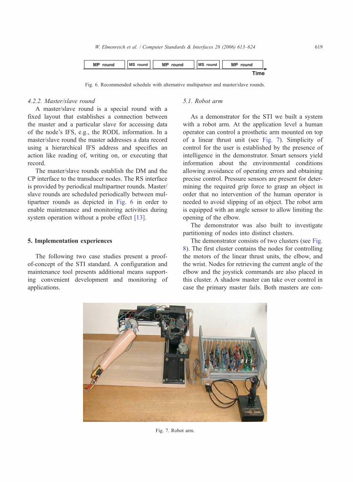
Fig. 7. Robo
5.1. Robot arm
As a demonstrator for the STI we built a system
with a robot arm. At the application level a human
operator can control a prosthetic arm mounted on top
of a linear thrust unit (see Fig. 7). Simplicity of
control for the user is established by the presence of
intelligence in the demonstrator. Smart sensors yield
information about the environmental conditions
allowing avoidance of operating errors and obtaining
precise control. Pressure sensors are present for deter-
mining the required grip force to grasp an object in
order that no intervention of the human operator is
needed to avoid slipping of an object. The robot arm
is equipped with an angle sensor to allow limiting the
opening of the elbow.
The demonstrator was also built to investigate
partitioning of nodes into distinct clusters.
The demonstrator consists of two clusters (see Fig.
8). The first cluster contains the nodes for controlling
the motors of the linear thrust units, the elbow, and
the wrist. Nodes for retrieving the current angle of the
elbow and the joystick commands are also placed in
this cluster. A shadow master can take over control in
case the primary master fails. Both masters are con-
t arm.
Master Master
Cluster 2Cluster 1
Intercluster
SlaveMotor 1
Slave
Motor 2Slave
Slave
Slave Slave
MasterShadow
Angle Joystik
Motor 3 Motor 4
TT
P/A
Bus
TT
P/A
Bus
SlavePressure 1
SlavePressure 2
SlaveIS: Hand
Master
Fig. 8. Architecture of robot arm transducer network.
W. Elmenreich et al. / Computer Standards & Interfaces 28 (2006) 613–624620
nected to the intercluster bus and act as intermediate
systems. In addition to their TTP/A master role, they
are slaves of a time-triggered backbone bus. The
second cluster contains a node acting as an interface
system for integrating the prosthetic hand into the
demonstrator. Two nodes equipped with pressure
sensors obtain measurements for grasping objects
intelligently.
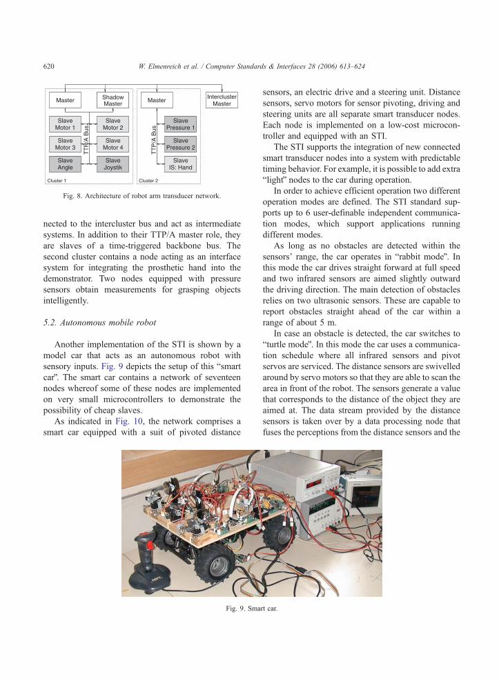
5.2. Autonomous mobile robot
Another implementation of the STI is shown by a
model car that acts as an autonomous robot with
sensory inputs. Fig. 9 depicts the setup of this bsmart
carQ. The smart car contains a network of seventeen
nodes whereof some of these nodes are implemented
on very small microcontrollers to demonstrate the
possibility of cheap slaves.
As indicated in Fig. 10, the network comprises a
smart car equipped with a suit of pivoted distance
Fig. 9. Sma
sensors, an electric drive and a steering unit. Distance
sensors, servo motors for sensor pivoting, driving and
steering units are all separate smart transducer nodes.
Each node is implemented on a low-cost microcon-
troller and equipped with an STI.
The STI supports the integration of new connected
smart transducer nodes into a system with predictable
timing behavior. For example, it is possible to add extra
blightQ nodes to the car during operation.
In order to achieve efficient operation two different
operation modes are defined. The STI standard sup-
ports up to 6 user-definable independent communica-
tion modes, which support applications running
different modes.
As long as no obstacles are detected within the
sensors’ range, the car operates in brabbit modeQ. Inthis mode the car drives straight forward at full speed
and two infrared sensors are aimed slightly outward
the driving direction. The main detection of obstacles
relies on two ultrasonic sensors. These are capable to
report obstacles straight ahead of the car within a
range of about 5 m.
In case an obstacle is detected, the car switches to
bturtle modeQ. In this mode the car uses a communica-
tion schedule where all infrared sensors and pivot
servos are serviced. The distance sensors are swivelled
around by servo motors so that they are able to scan the
area in front of the robot. The sensors generate a value
that corresponds to the distance of the object they are
aimed at. The data stream provided by the distance
sensors is taken over by a data processing node that
fuses the perceptions from the distance sensors and the
rt car.
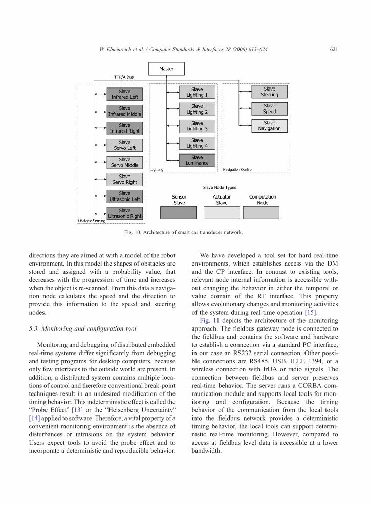
Fig. 10. Architecture of smart car transducer network.
W. Elmenreich et al. / Computer Standards & Interfaces 28 (2006) 613–624 621
directions they are aimed at with a model of the robot
environment. In this model the shapes of obstacles are
stored and assigned with a probability value, that
decreases with the progression of time and increases
when the object is re-scanned. From this data a naviga-
tion node calculates the speed and the direction to
provide this information to the speed and steering
nodes.
5.3. Monitoring and configuration tool
Monitoring and debugging of distributed embedded
real-time systems differ significantly from debugging
and testing programs for desktop computers, because
only few interfaces to the outside world are present. In
addition, a distributed system contains multiple loca-
tions of control and therefore conventional break-point
techniques result in an undesired modification of the
timing behavior. This indeterministic effect is called the
bProbe EffectQ [13] or the bHeisenberg UncertaintyQ[14] applied to software. Therefore, a vital property of a
convenient monitoring environment is the absence of
disturbances or intrusions on the system behavior.
Users expect tools to avoid the probe effect and to
incorporate a deterministic and reproducible behavior.
We have developed a tool set for hard real-time
environments, which establishes access via the DM
and the CP interface. In contrast to existing tools,
relevant node internal information is accessible with-
out changing the behavior in either the temporal or
value domain of the RT interface. This property
allows evolutionary changes and monitoring activities
of the system during real-time operation [15].
Fig. 11 depicts the architecture of the monitoring
approach. The fieldbus gateway node is connected to
the fieldbus and contains the software and hardware
to establish a connection via a standard PC interface,
in our case an RS232 serial connection. Other possi-
ble connections are RS485, USB, IEEE 1394, or a
wireless connection with IrDA or radio signals. The
connection between fieldbus and server preserves
real-time behavior. The server runs a CORBA com-
munication module and supports local tools for mon-
itoring and configuration. Because the timing
behavior of the communication from the local tools
into the fieldbus network provides a deterministic
timing behavior, the local tools can support determi-
nistic real-time monitoring. However, compared to
access at fieldbus level data is accessible at a lower
bandwidth.

Fieldbus SmartTransducer Interface
FieldbusGateway Node
RS232 or any otherStandard Interface
Internet TCP/IP orCORBA Interface
Smart Sensors and Actuators
InternetorCORBA ORBServer
MonitoringApplication(Local)
MonitoringApplication(Remote)
DiagnosisTools Configuration
Tool
Virt
ual A
cces
s to
any
fiel
dbus
nod
e
Fig. 11. System architecture.
ApplicationNetwork Process to Application
Interface File SystemTransparent Network Access,
CORBA Gateway
tan
dar
d
W. Elmenreich et al. / Computer Standards & Interfaces 28 (2006) 613–624622
The communication module running on the PC is a
CORBA object. The CORBA middleware enables the
transparent access of remote service applications to
the fieldbus network through, e.g. the Internet. This
interface is independent of the employed protocols
and physical layers at fieldbus level.
RepresentationData Representation andEncryption
SessionInterhost Communication
TransportEnd-To-End Connections
and Reliability
NetworkPath Determination
and IP (Logical Addressing)
Data LinkMedia Access Control and
Time-TriggeredFieldbusProtocol O
MG
Sm
art
Tra
nsd
uce
rIn
terf
ace
S
6. Relation to ISO/OSI model
Because of the timing requirements on control sys-
tems, fieldbus systems implement several layers of the
OSI (Open Systems Interconnection) model at once, in
most cases there is a representation for the OSI levels 1
(physical layer), 2 (data link layer), and 7 (application)
whereas OSI layers 3. . .6 are usually void since they
have no counterpart in the fieldbus world.1
1 A notable exception is the LON (Local Operating Network)
fieldbus, a communication system for building automation, which
implements all 7 layers of the basic OSI model.
The here presented STI standard defines OSI layers
from application layer to link layer, whereas there are
no features defined that would belong to layers 3. . .6.Fig. 12 defines the relation between the OSI standard
and the OMG smart transducer interface.
The IFS at the top level acts as transparent network
interface for the application and as gateway to the
CORBA network. The specified TDMA bus arbitra-
tion scheme and the codification of message length
refer to the data link layer of the OSI model. Accord-
ing to the standard, the physical layer is open to
various implementations, as long as the communica-
tion parameters of the chosen physical layer match the
application’s real-time requirements on timing and
throughput. Thus, any compatible physical layer stan-
dard such as RS 485, ISO 9141, CAN physical layer,
IrDA, etc. may be used.
7. Discussion and conclusion
One requirement stated in the request for proposal
by the OMG has been the real-time capabilities of the
smart transducer interface. The STI supports hard real-
time communication by introducing a time-triggered
communication scheme that is a priori specified before
the RS interface of the system comes into operation.
Generally, time-triggered systems require an increased
effort in the design phase of the system, but provide an
and Logical Link Control
Physical LayerMedia, Signal and
Binary Transmission
Physical Layer
Fig. 12. Relation to layers of OSI model.

W. Elmenreich et al. / Computer Standards & Interfaces 28 (2006) 613–624 623
easier verification of the temporal correctness. Since
time-triggered systems are designed according to the
principle of resource adequacy [16], it is guaranteed
that sufficient computing resources are available to
handle the specified peak load scenario. On the other
hand, time-triggered systems are often blamed for their
bad flexibility. The STI overcomes this limitation by
introducing means to configure the interaction of the
components via the CP interface.
The RS interface provides composability, guaran-
teed timeliness, and hides the components’ internals.
The DM and CP interfaces involve inherently event-
triggered activities, which require an event-triggered
communication service. These interfaces cannot inva-
lidate the temporal behavior of the RS interface and
support full access to component internals — as
required by a maintenance engineer.
The specification of interfaces should be complete
and of minimal cognitive complexity. Cognitive com-
plexity can be minimized by restricting interactions via
carefully designed interfaces and by providing access
restrictions. The kind of information that must be
available via an interface depends on the purpose of
the particular interface. For example, a properly
designed operational interface hides component inter-
nals, thereby allowing a component to form a mean-
ingful abstraction. The corresponding operational
interface specification stipulated during architecture
design should incorporate a precise specification of a
componentTs inputs and outputs in both the temporal
and the value domain. A maintenance engineer on the
other hand, might require access to intermediate com-
putational results for locating the origin of an incorrect
system behavior.
The STI standard meets the requirement for com-
plete interfaces of minimal cognitive complexity by
introducing three different types of interfaces of a
component. The separation (RS, DM, and CP inter-
face) is done according to the interface purpose, the
necessary level of visibility of component internal
information, and the type of the temporal interaction
patterns. Such a separation minimizes complexity in
contrast to a single interface type incorporating sup-
port for all possible interactions.
The STI standard also specifies the provision of
the three interface types through a CORBA server.
However, currently there is no CORBA architecture
for effectively supporting the temporal requirements
to establish the RS interface. Current priority-based
approaches like real-time CORBA require complete
knowledge about all other service requests and their
corresponding priority values in the whole CORBA
network when guarantees about the temporal beha-
vior are required. Furthermore, the availability of a
global notion of time allows to record the instant of
the acquisition of a real-time entityTs state in each
observation.
As a proof of concept, we have implemented two
case studies of the STI. The first case study comprises a
demonstrator with a robot arm that is instrumented by a
smart transducer network partitioned into two clusters.
The second case study is an autonomous mobile robot,
which shows the integration of new nodes and efficient
communication despite of static communication sche-
dules. The case studies show that the STI standard is an
interesting option for a wide range of networked sen-
sing and control applications. The STI provides many
features that are required by fieldbus applications for
automotive or automation industries. Supported fea-
tures are the real-time capability, the encapsulation of
the node’s internals, and a universal address space with
the interface file system. The STI can be implemented
on low-cost Commercial-off-the-Shelf (COTS) hard-
ware and supports various bus media types.
Acknowledgments
We would like to thank Christian El Salloum who
gave valuable inputs to an earlier version of this paper.
This work was supported in part by the Austrian Min-
istry of Science project TTSB and by the European IST
projects DSoS under contract No IST-1999-11585 and
NextTTA under contract No IST-2001-32111.
References
[1] L.-B. Fredriksson. CanKingdom and dependable CAN sys-
tems. available at http://www.cankingdom.org.
[2] BOSCH. Osek/vxd operating system— version 2.1 revision 1.
available at http://www-iiit.etec.uni-karlsruhe.de/osek/, Dec.
2000.
[3] Institute of Electrical and Electronics Engineers, Inc. IEEE Std
1451.2-1997, Standard for a Smart Transducer Interface for
Sensors and Actuators– Transducer to Micro-processor Com-
munication Protocols and Transducer Electronic Data Sheet
(TEDS) Formats, 1997.

W. Elmenreich et al. / Computer Standards & Interfaces 28 (2006) 613–624624
[4] A. Meschi, M. Di Natale, M. Spuri, Priority inversion at the
network adapter when scheduling messages with earliest dead-
line techniques, Proceedings of EURWRTS ’96, 1996, pp.
243–248.
[5] H. Kopetz, M. Holzmann, W. Elmenreich, A universal smart
transducer interface: TTP/A, International Journal of Com-
puter System Science and Engineering 16 (2) (2001 March)
71–77.
[6] Object Management Group (OMG). Smart Transducers Inter-
face V1.0, January 2003. Specification available at http://doc.-
omg.org/formal/2003-01-01 as document ptc/2002-10-02.
[7] M. Felser, T. Sauter, The fieldbus war: history or short break
between battles? Proceedings of the 4rd IEEE International
Workshop on Factory Communication Systems, Vasteras,
Sweden, 2002 August, pp. 73–79.
[8] H. Kopetz, Real-Time Systems, Design Principles for Distrib-
uted Embedded Applications, Kluwer Academic Publishers,
Boston, Dordrecht, London, 1997.
[9] A. Ran, J. Xu, Architecting software with interface objects,
Proceedings of the 8th Israeli Conference on Computer-Based
Systems and Software Engineering, 1997, pp. 30–37.
[10] H. Kopetz, R. Nossal, Temporal firewalls in large distributed
real-time systems, Proceedings of the 6th IEEE Workshop on
Future Trends of Distributed Computing Systems (FTDCS
’97), 1997, pp. 310–315.
[11] H. Kopetz, R. Obermaisser, Temporal composability, IEE’s
Computing and Control Engineering Journal (2002)1985
(May).
[12] W. Elmenreich, W. Haidinger, H. Kopetz, Interface design for
smart transducers, IEEE Instrumentation and Measurement
Technology Conference, Budapest, Hungary 3 (2001 May)
1642–1647.
[13] J. Gait, A probe effect in concurrent programs, Software
Practice and Experience 16 (3) (1986 March) 225–233.
[14] C.H. Ledoux, D. Stott Parker, Saving traces for Ada debug-
ging, Ada in Use (1985 International Ada Conference),
Cambridge University Press, Cambridge, England, 1985
May, pp. 97–108.
[15] P. Peti, R. Obermaisser, W. Elmenreich, T. Losert, An archi-
tecture supporting monitoring and configuration in real-time
smart transducer networks, Proccedings of the 1st IEEE Inter-
national Conference on Sensors (IEEE SENSORS 2002),
Orlando, Florida, USA, 2002 (June).
[16] H.W. Lawson, Parallel Processing in Industrial Real-Time
Applications, Prentice Hall, Englewood Cliffs, New Jersey,
1992.