A Spectral Finite-Volume Method for the Shallow … 2004 CHOI ET AL. 1777 q 2004 American...
16
JULY 2004 1777 CHOI ET AL. q 2004 American Meteorological Society A Spectral Finite-Volume Method for the Shallow Water Equations BYOUNG-JU CHOI Institute of Marine and Coastal Sciences, Rutgers–The State University of New Jersey, New Brunswick, New Jersey MOHAMED ISKANDARANI Rosenstiel School of Marine and Atmospheric Science, University of Miami, Miami, Florida JULIA LEVIN AND DALE B. HAIDVOGEL Institute of Marine and Coastal Sciences, Rutgers University–The State University of New Jersey, New Brunswick, New Jersey (Manuscript received 18 July 2003, in final form 26 January 2004) ABSTRACT A spectral finite-volume (SFV) method is proposed for the numerical solution of the shallow water equations. This is the first phase in the development of a layered (isopycnal) ocean model. Its target applications include, in particular, the simulation of the wind-driven oceanic circulation in geometrically complex basins where layer outcropping and/or isopycnal–bathymetry intersection must be handled explicitly. The present formulation is geometrically flexible and can extend accuracy to arbitrary high order with no change to the basic algorithm. A flux-corrected transport (FCT) algorithm ensures the stability of the computations in regions of vanishing layer thickness and in areas where the flow features are underresolved. The spatial discretization is based on a two-level grid: a globally unstructured elemental grid and a locally structured grid consisting of N 3 N quad- rilateral cells within each element. The numerical solution is continuous within each element but discontinuous across elements; the discontinuity is resolved by upwinding along characteristics. The accuracy and convergence rate of the SFV method are verified on two linearized problems amenable to analytical solution; the SFV solution exhibits a convergence order of N 1 1 for smooth solutions. The FCT portion of the model is tested by simulating the formation of an oblique hydraulic jump in a supercritical channel flow. The model is then applied to simulate, in reduced-gravity mode, the double-gyre and wind-driven upper-ocean circulations in a square basin. Finally, the previous experiment is repeated in the North Atlantic basin to illustrate the application of the model in a realistic geometry. 1. Introduction This article describes the development and testing of a high-order, geometrically flexible, and ‘‘robust’’finite- volume method to solve the shallow water equations. The long-term goal is the development of a three-di- mensional, hydrostatic ocean model that relies on iso- pycnal (density) coordinates in the vertical direction. The present model is a first step toward that goal. The choice of vertical coordinate system, and its as- sociated discretization, is one of the central issues faced by ocean model developers. The three common choices, geopotential (z level), terrain-following, or isopycnal coordinates (Haidvogel and Beckmann 1999), are not optimal across all flow regimes in the ocean as dem- onstrated in several intermodel comparison experiments Corresponding author address: Byoung-Ju Choi, Institute of Ma- rine and Coastal Sciences, 71 Dudley Road, New Brunswick, NJ 08901-8521. E-mail: [email protected] (Willebrand et al. 2001; Chassignet et al. 2000). The majority of existing finite-element (e.g., Lynch and Wer- ner 1991; Iskandarani et al. 2003) and unstructured-grid finite-volume (Chen et al. 2003) ocean models belong to the class of terrain-following models. This choice largely reflects the desire to extend the models’ geo- metric accuracy in the vertical direction and to represent as faithfully as possible oceanic topography. Our effort is aimed at developing an unstructured- grid-based model with an alternative, isopycnal, coor- dinate system in the vertical. The main applications tar- geted are idealized process-oriented problems enclosed within realistic basin geometries (e.g., the wind-driven circulation in the North Atlantic Ocean). The main ad- vantages of an isopycnal representation of the vertical structure of oceanic flows are elimination of spurious diapycnal diffusion, reduction of pressure gradient er- rors near steep topography, efficient representation of baroclinic processes per vertical degrees of freedom, and finally ease of implementation since an isopycnal model
Transcript of A Spectral Finite-Volume Method for the Shallow … 2004 CHOI ET AL. 1777 q 2004 American...

JULY 2004 1777C H O I E T A L .
q 2004 American Meteorological Society
A Spectral Finite-Volume Method for the Shallow Water Equations
BYOUNG-JU CHOI
Institute of Marine and Coastal Sciences, Rutgers–The State University of New Jersey, New Brunswick, New Jersey
MOHAMED ISKANDARANI
Rosenstiel School of Marine and Atmospheric Science, University of Miami, Miami, Florida
JULIA LEVIN AND DALE B. HAIDVOGEL
Institute of Marine and Coastal Sciences, Rutgers University–The State University of New Jersey, New Brunswick, New Jersey
(Manuscript received 18 July 2003, in final form 26 January 2004)
ABSTRACT
A spectral finite-volume (SFV) method is proposed for the numerical solution of the shallow water equations.This is the first phase in the development of a layered (isopycnal) ocean model. Its target applications include,in particular, the simulation of the wind-driven oceanic circulation in geometrically complex basins where layeroutcropping and/or isopycnal–bathymetry intersection must be handled explicitly. The present formulation isgeometrically flexible and can extend accuracy to arbitrary high order with no change to the basic algorithm.A flux-corrected transport (FCT) algorithm ensures the stability of the computations in regions of vanishinglayer thickness and in areas where the flow features are underresolved. The spatial discretization is based on atwo-level grid: a globally unstructured elemental grid and a locally structured grid consisting of N 3 N quad-rilateral cells within each element. The numerical solution is continuous within each element but discontinuousacross elements; the discontinuity is resolved by upwinding along characteristics. The accuracy and convergencerate of the SFV method are verified on two linearized problems amenable to analytical solution; the SFV solutionexhibits a convergence order of N 1 1 for smooth solutions. The FCT portion of the model is tested by simulatingthe formation of an oblique hydraulic jump in a supercritical channel flow. The model is then applied to simulate,in reduced-gravity mode, the double-gyre and wind-driven upper-ocean circulations in a square basin. Finally,the previous experiment is repeated in the North Atlantic basin to illustrate the application of the model in arealistic geometry.
1. Introduction
This article describes the development and testing ofa high-order, geometrically flexible, and ‘‘robust’’ finite-volume method to solve the shallow water equations.The long-term goal is the development of a three-di-mensional, hydrostatic ocean model that relies on iso-pycnal (density) coordinates in the vertical direction.The present model is a first step toward that goal.
The choice of vertical coordinate system, and its as-sociated discretization, is one of the central issues facedby ocean model developers. The three common choices,geopotential (z level), terrain-following, or isopycnalcoordinates (Haidvogel and Beckmann 1999), are notoptimal across all flow regimes in the ocean as dem-onstrated in several intermodel comparison experiments
Corresponding author address: Byoung-Ju Choi, Institute of Ma-rine and Coastal Sciences, 71 Dudley Road, New Brunswick, NJ08901-8521.E-mail: [email protected]
(Willebrand et al. 2001; Chassignet et al. 2000). Themajority of existing finite-element (e.g., Lynch and Wer-ner 1991; Iskandarani et al. 2003) and unstructured-gridfinite-volume (Chen et al. 2003) ocean models belongto the class of terrain-following models. This choicelargely reflects the desire to extend the models’ geo-metric accuracy in the vertical direction and to representas faithfully as possible oceanic topography.
Our effort is aimed at developing an unstructured-grid-based model with an alternative, isopycnal, coor-dinate system in the vertical. The main applications tar-geted are idealized process-oriented problems enclosedwithin realistic basin geometries (e.g., the wind-drivencirculation in the North Atlantic Ocean). The main ad-vantages of an isopycnal representation of the verticalstructure of oceanic flows are elimination of spuriousdiapycnal diffusion, reduction of pressure gradient er-rors near steep topography, efficient representation ofbaroclinic processes per vertical degrees of freedom, andfinally ease of implementation since an isopycnal model

1778 VOLUME 132M O N T H L Y W E A T H E R R E V I E W
can be obtained by vertically stacking a set of shallowwater models.
Isopycnal models have disadvantages. The major oneamong them, from a computational point of view, is theneed to contend with vanishing layer thicknesses andisopycnals intersecting topography. Successful, finite-difference-based isopycnal models rely on some formof total variation diminishing (TVD) or positivity pre-serving schemes to cope with the above problems (Bleckand Boudra 1986; Hallberg and Rhines 1996). A similarapproach is pursued herein to allow for layer outcrop-ping to occur.
We have chosen the finite-volume (FV) method tobuild our present model because of its flexible grids andthe availability of several ‘‘robust’’ slope/flux limitingprocedures to enforce the TVD property. In addition,finite-volume methods possess the local conservationproperty, a very desirable feature during long integra-tions. The geometric flexibility in the present modelderives directly from the unstructured nature of its com-putational grids. These grids are based on the decom-position of the flow domain into triangular or quadri-lateral elements. Their size and orientation can be ad-justed to fit the geometric and dynamical requirementsof the simulation. Complicated basin geometry and localgrid refinement in dynamically active regions can thenbe handled with ease.
Finite-volume formulations have traditionally beenrestricted to first- or second-order accuracy when ap-plied to unstructured grids (Alcrudo and Garcia-Navarro1993; Chen et al. 2003). A potential outcome is an ex-cessive amount of numerical errors, largely dissipativebut also dispersive in nature, that can only be controlledby a large increase in the number of finite volumes, andhence computational cost. The main limitation of theseschemes is that their cells contain 1 degree of freedomper cell (the solution average), and hence a collectionof cells is needed to fit a polynomial of degree higherthan 1. This collection is complicated to assemble giventhe quasi-random arrangement of cells in an unstruc-tured grid. The difficulty increases dramatically whendesigning higher-order schemes.
Giannakouros and Karniadakis (1992) and Giannak-ouros et al. (1994) proposed an alternative FV discret-ization scheme that builds on the hierarchy of gridsavailable in the spectral element method. At the globallevel, the grid is unstructured and is composed of ele-ments within which a locally structured grid is embed-ded. The spectral element machinery can then be usedto construct a high-order polynomial covering the cellswithin an element. The method consists of a (structured)collection of finite-volume cells arranged into elements,such that the operations needed for high-order inter-polation, reconstruction, integration, and differentiationare considerably reduced. Giannakouros et al. (1994)used quadrilateral elements for the spatial discretization.The finite-volume cell boundaries are defined by theGauss–Lobatto roots of the Chebyshev polynomials. In
addition, the authors incorporated a flux-corrected trans-port (FCT) algorithm (Zalesak 1979) to handle shockwaves and strong discontinuities. The spectral elementinterpolation machinery provides the high-order fluxeswhile the low-order fluxes consist of piecewise-constantinterpolation at the cell levels. This particular imple-mentation of the spectral element–FCT method enforcesthe continuity of the function across elemental bound-aries during the reconstruction step, which complicatesits application to highly unstructured grids. Further-more, the multidimensional version of the method re-constructs state variables by tensor product applicationof one-dimensional operators, and performance there-fore degrades as the element shapes depart significantlyfrom that of a rectangle.
Kopriva (1996) and Kopriva and Kolias (1996) pre-sented a similar high-order, unstructured-grid method tosolve the compressible Euler equations: cells aregrouped into elements so that high-order interpolationand differentiation can be used. This scheme does notrely on a finite-volume formulation but is based insteadon enforcing the strong form of the differential equa-tions. Most importantly, this scheme does not requirethe continuity of the solution across element boundariesand relies instead on the flow of characteristic infor-mation to resolve the discontinuity at element edges.The discontinuous representation simplifies the scheme,particularly for highly unstructured grids. The appli-cation of the method to problems with smooth solutionsconfirms its spectral-like character when the interpola-tion order within elements has been increased. To theauthors’ knowledge no flux limiter was implementedfor this particular scheme.
Wang (2002) introduced a discontinuous high-orderfinite-volume method for the solution of conservationlaws in one-space dimension, which he refers to as aspectral finite-volume (SFV) method. The SFV methodhas been extended to solve a two-dimensional scalarequation on a fully unstructured grid (Wang and Liu2002). The two-dimensional elements are triangles thatare further subdivided into polygonal control volumecells to support high-order data reconstructions. Severaltotal-variance-diminishing and total-variance-boundedlimiters have been adapted for the nonoscillatory cap-turing of discontinuities.
In this paper, we propose a new formulation for anSFV method based on quadrilateral elements. The quad-rilateral shape of elements makes the choice of quad-rilateral finite-volume cells natural. The solution in ourapproach is interpolated with a high-order polynomialwithin an element and is discontinuous across elements;characteristic information is used to resolve the discon-tinuity. An FCT algorithm is incorporated to enforcemonotonicity near strong discontinuities or underre-solved gradients and forms the basis for handling van-ishing layer thickness in our shallow water simulations.
In section 2, we briefly describe the system of shallowwater equations and present the formulation of the SFV

JULY 2004 1779C H O I E T A L .
method. Accuracy and convergence rates are calculatedfor two simple problems amenable to analytic solution:the pure advection of a Gaussian hill in a rotating cir-cular flow and a linear standing wave sloshing in asquare basin. The FCT algorithm is reviewed in section3 for the monotonic advection of mass and momentum,and the combined SFV–FCT scheme is tested for theproblem of shock formation in a supercritical channelflow. In section 4, a reduced-gravity ocean model isdescribed based on the SFV method. The model is thentested on two problems: double gyre, wind-driven cir-culation with layer outcropping and an upper-ocean cir-culation in a realistic North Atlantic Ocean. We con-clude in section 5 with some remarks on future work.
2. Spectral finite-volume method
a. Shallow water equations
The shallow water equations (SWE) can be obtainedby vertical integration of the 3D Navier–Stokes equa-tions along with the assumptions of hydrostatic pressureand a vertically uniform horizontal velocity profile. Thissystem of nonlinear equations representing mass andmomentum conservation is primarily hyperbolic andmay lead to discontinuous solutions. The SWE in vectorand conservation form are
]U ]E ]G1 1 5 S, (1)
]t ]x ]y
where E and G represent the fluxes along the x and ydirections, respectively. The vector of unknowns is
h
U 5 uh , (2) yh
where h represents the layer thickness, and u and y standfor the depth-averaged velocity components along thex and y directions, respectively. The Cartesian compo-nents of the flux vectors and source terms are
yh uh
uyh 1 2 2E 5 u h 1 gh , (3)G 5 , 12
2 2 y h 1 gh2uyh
0t xf yh 1 2 kuh 1 = · (nh=u) S 5 . (4)r t y2 fuh 1 2 kyh 1 = · (nh=y) r
Here, g is the gravitational acceleration; f is the Coriolisparameter; t is the wind stress; r is the constant waterdensity; k is the bottom friction coefficient; and n is thehorizontal viscosity.
b. Finite-volume formulation
We stress that the present model is not based on avariational form, but rather on a finite-volume formu-lation (Alcrudo and Garcia-Navarro 1993). Equation (1)is spatially integrated over a region V to obtain theintegral form of the equations:
]UdV 1 F · n dG 5 S dV, (5)E ER]t
V VG
after application of the Gauss theorem. Here n is theoutward unit normal to the boundary G of V, andF · n 5 Enx 1 Gny. The first volume integral representsthe time rate of change of the amount of U in V, whilethe surface integral is the total flux of U through thecell edges. Define as the average of U over V, thatUis,
1U 5 U dV, (6)EV
V
where V is the area of V in two dimensions and thevolume in three dimensions. The finite-volume form ofthe SWE can now be written as
dU 11 F · n dG 5 S. (7)Rdt V
G
Equation (7) is still exact; the numerical approximationcomes from evaluating the boundary integral and in timestepping the area averages.
Equation (7) is an ordinary differential equation thatmust be integrated in time. We choose a third-orderRunge–Kutta (RK3) scheme for the time integration asa good compromise between practicality and accuracy.The RK3 scheme is expressed as
1R(U, t) 5 ADV(E, G) 1 S, ADV(E, G) 5 2 F · n dGRV
G
R 5 R(U, t), U 5 U(t) 1 DtR0 1 0
Dt R 1 R0 1R 5 R(U , t 1 Dt), U 5 U(t) 11 1 2 2 2
Dt R 1 4R 1 R0 2 1R 5 R U , t 1 , U(t 1 Dt) 5 U(t) 1 Dt . (8)2 21 22 6

1780 VOLUME 132M O N T H L Y W E A T H E R R E V I E W
FIG. 1. Sketch of a spectral element and its N 3 N cells aftermapping to the unit square in the computational plane. Cell Vkl isdefined by [jk21, jk] 3 [hl21, hl] where jk and hl are the Gauss–Lobatto–Legendre roots. Circles represent Gauss–Legendre points( k and l) where variables are collocated. Solid dots along four edgesj hof cell Vkl are the Gauss quadrature points for high-order computationof fluxes.
Notice that the scheme evolves the cell averages in timewhile the fluxes and sources require the function values.An efficient and accurate machinery must then be de-vised to transform cell averages into function values(the reconstruction step), and vice versa (the averagingstep). In the next section, we turn our attention to theissues of spatial discretization, reconstruction, and cell-average computation.
c. High-order reconstruction
The spatial discretization is based on a two-level gridin order to endow the method with geometrical flexi-bility and high-order accuracy. The first level consistsof partitioning the flow domain into quadrilateral sub-regions, which we refer to in the following as elements.The elemental grid is allowed to be unstructured; theadjacency pattern can hence be varied according to geo-metric and accuracy requirements. Each element is sub-divided into a structured grid of N 3 N cells and istransformed by one-to-one mapping into a computa-tional plane as shown in Fig. 1 (Karniadakis and Sher-win 1999). This local structured grid permits the use ofhigh-order polynomials to interpolate, average, and re-construct the solution; it also plays a role in formulatingthe FCT portion of the algorithm as will be seen insection 3. Each element then contains N 2 cells overwhich Eq. (7) will be solved.
In order to take advantage of the interpolation prop-erties of spectral methods (Boyd 1994), we choose our
interpolation points to be the Gauss–Legendre roots ofLegendre polynomial of degree N: LN( k) 5 0 with kj5 1, . . . , N, where LN(j) is the Legendre polynomialof degree N. The cell edges are the (N 1 1) Gauss–Lobatto–Legendre roots of the same Legendre poly-nomial:
2(1 2 j )L9 (j ) 5 0, k 5 0, 1, . . . , N. (9)k N k
It is easy to show that the two sets of roots are staggeredso that jk21 , k , jk. The two-dimensional grid isjobtained by tensor product combination of the one-di-mensional grid. The cell Vkl associated with the cell-averaged scalar variable kl is defined by the regionU[jk21, jk] 3 [hl21, hl]. A point value in our scheme isinterpolated via a high-order Lagrangian interpolant:
N N
U(j, h) 5 U h (j)h (h), (10)O O i j i ji51 j51
where j and h are the coordinates in the computationalplane, Uij is the function value at the collocation point( i, j), and hi(j) are the Gauss–Legendre cardinal func-j htions:
L (j)Nh (j) 5 , i 5 1, 2, . . . , N. (11)i L9 (j )(j 2 j )N i i
The cell averages kl can now be computed by inte-Ugrating the Lagrangian interpolants over the area of eachcell:
h jN N l k1U 5 U h (j)h (h) |J | dj dh,O Okl i j E E i jV i51 j51kl h jl21 k21
(12)
where Vkl is the area of cell(k, l) and J 5 (xj yh 2 xhyj)is the Jacobian of the mapping between physical spaceand computational space. The above operations can becast as a matrix vector product that maps the N 2 valuesof Uij into the N 2 cell averages kl:U
N N
U 5 A U ,O O kl,i jkl i ji51 j51
h jl k1A 5 h (j)h (h) |J | dj dh. (13)kl,i j E E i jVkl h jl21 k21
Unlike the scheme proposed in Sidilkover and Kar-niadakis (1993) and Giannakouros and Karniadakis(1994), the interpolation is discontinuous at elementboundaries, and we make no attempt at enforcing con-tinuity. This makes the scheme compact as the recon-struction is now local to each element. A further ad-vantage of our scheme is that it is now possible touniquely invert the mapping between the function valuesUij and the cell averages kl since the averaging matrixUA is square. For the given vector of dimension N 2,Uwe reconstruct the N 2 function values U 5 A
21. TheU
matrix A can be computed and stored for each elementas a preprocessing step.

JULY 2004 1781C H O I E T A L .
FIG. 2. Structure of the HLLC approximate Riemann solver. Ini-tially (t 5 0) there are two constant states on either side of the wallat x 5 0. Once the wall is removed, three waves (rarefaction wavewith speed WL, contact discontinuity W
*, and shock wave WR) prop-
agate away from the boundary. Solution consists of four constantstates (UL, U*L, U*R, and UR) separated from each other by the threewave speeds.
A high-order quadrature is used to evaluate theboundary integrals in Eq. (7). We adopt Gauss quad-rature to evaluate these boundary integrals since it pro-vides high accuracy and does not require flux evaluationat element corners (thus obviating the need to figure outthe upwinding directions at these corners; Fig. 1). Weuse N Gauss quadrature points, which leads to an exactintegration formula for polynomials of degree 2N 2 1or less:
N
F · n dG 5 w F [U(x , y )] · nG, (14)OE j j jj51
where wj are the Gauss quadrature weights, (xj, yj) arethe Gauss quadrature points, and G is length of a cellside. The interpolation of physical variables along cellsides is based on the interpolating polynomial (10).
d. Interelemental conditions
The discontinuous representation complicates the fluxcomputations near element boundaries where the solu-tion is two valued. Upwinding along the characteristicdirection is required to resolve this discontinuity and tocalculate a unique value for the boundary flux; we usean approximate Riemann solver based on the Harten–Lax–van Leer contact (HLLC) flux as described by Toro(1999, 2001). We briefly describe this procedure in thissection and refer the reader to the aforementioned ref-erences for more details.
The HLLC approach assumes that four constant statesUL, U*L, U*R, and UR are separated by three waves withspeeds of WL, W*, and WR for the smallest, middle, andlargest signal velocities in the solution of the Riemannproblem in Fig. 2. Subscripts L and R refer to left- andright-going waves emanating from the elemental bound-ary, and * refers to the middle wave. For the homo-geneous shallow water equations (i.e., S 5 0), integra-
tion of the conservation laws (5) over an appropriatecontrol volume [xL, xR] 3 [0, T] gives the HLLC nu-merical flux as
F if 0 # W ,L LF* if W # 0 # W*,L Lhllc F 5 (15)x50 F* if W* # 0 # W ,R RF if W # 0 R R
where
F 5 F (U ), M 5 L or R,M M
F* 5 F 1 W (U* 2 U ),L L L L L
F*R 5 F 1 W (U* 2 U ). (16)R R R R
The states U*L and U*R are given by
1 W 2 u M MU* 5 h W* , M 5 L or R. (17) M M1 2 W 2 W*M c M
For nonzero values of hL and hR (i.e., for nonzero waterdepth) the wave speed estimates are suggested by Toro(2001) as
W 5 u 2 c q ,L L L L
W 5 u 1 c q ,R R R R
1W* 5 (u 1 u ) 1 c 2 c , (18)L R L R2
where
1 (h* 1 h )h*M if h* . hM2! [ ]q 5 , M 5 L or R,2 hM M
1 if h* # h M
(19)2
1 1 1h* 5 (c 1 c ) 1 (u 2 u ) , (20)L R L R[ ]g 2 4
and the gravity wave speed
c 5 Ïgh , M 5 L or R. (21)M M
e. Numerical stability
The stability in the finite-volume formulation is re-stricted by the Courant–Friedrichs–Lewy (CFL) con-dition
min(r )i, jDt # , (22)
2 22 max[(c 1 Ïu 1 y ) ]i, j
where ri,j represents the whole set of distances betweenevery center point of cell (i, j) and those of its fouradjacent cells.

1782 VOLUME 132M O N T H L Y W E A T H E R R E V I E W
FIG. 3. Rotation of Gaussian hill experiment. We plot the L2 norm of the global error of layer thickness for (a) fixed order N and (b) fixedelement partition K; N 3 N points are used for the interpolation of variables within an element; Dx is the average grid size, which is calculatedby adding length of all cell sides and dividing by the number of sides.
f. Numerical experiments and convergence tests
Before proceeding further, we illustrate by numericalexamples the convergence characteristics of the pro-posed SFV scheme for smooth problems. The two sam-ple problems consist of a simple scalar advection equa-tion, the simplest possible hyperbolic system, and thelinearized shallow water equations. The first confirmsthe basic soundness of the SFV machinery, while thesecond tests the interfacial conditions. Both tests areamenable to analytic solution, which we use to computeerrors. As expected, the errors and the convergence ratedepend on the number of elements and on the order ofinterpolation. To compare the SFV solution of the fullshallow water equations with a well-established finite-difference model solution, we simulate the westwardpropagation of a monopole vortex in an idealized basin.
1) ROTATION OF A GAUSSIAN HILL
The scalar problem we consider is the standard ad-vection of a passive tracer in a steady velocity field thatcorresponds to solid-body rotation. The equations andinitial conditions are
]h ]hu ]hy 2 2(r / l )1 1 5 0, h(x, y, 0) 5 e ,]t ]x ]y
2 21 12r 5 x 2 1 y 2 ,1 2 1 24 2
1 1u 5 2v y 2 , y 5 v x 2 .1 2 1 22 2
(23)
Here, h is interpreted as the concentration of a tracer.The e-folding length scale is set to l 5 1/16. Periodicboundary conditions are imposed on all sides of a squarebasin with unit length, and v is set to 2p so that theperiod of rotation is 1. After one revolution the exactsolution coincides with the initial Gaussian distribution.
Figure 3 shows the error and convergence rates of theSFV solution after a single rotation of the Gaussian hill.The interpolation order is held fixed for each of the curvesappearing in Fig. 3a, and the number of elements is in-creased; this corresponds to the so-called h refinement.The constant slope for fixed N shows that the errors de-crease algebraically fast as the number of elements in-creases; the slope of the line is approximately N 1 1.Higher-order polynomial interpolation results in smallererrors than low-order polynomials for the same grid size(cell size, Dx) regardless of grid resolution. Figure 3bshows the exponential decrease in the error with the orderof the interpolation polynomial for fixed element partitionK whose square is the total number of elements.
2) STANDING WAVE IN A SQUARE BASIN
To illustrate the accuracy and convergence rate of theSFV method on a hyperbolic system, we apply it tosolve the linearized inviscid shallow water equations.

JULY 2004 1783C H O I E T A L .
The problem consists of a standing wave sloshing in arectangular basin of unit width. The boundary condi-tions are impermeable walls, and the initial conditions
are u 5 y 5 0, and h 5 H 1 cos(px) cos(py), whereH is the resting layer thickness. The linearized equationsand the solution to the problem as posed are
]u ]h g1 g 5 0 u 5 sin(px) cos(py) sin(pÏ2gHt)!]t ]x 2H ]y ]h g 1 g 5 0 y 5 cos(px) sin(py) sin(pÏ2gHt) (24)!]t ]y 2H]h ]u ]y 1 H 1 H 5 0, h 5 H 1 cos(px) cos(py) cos(pÏ2gHt).
]t ]x ]y
We have normalized the gravity coefficient to 1 and setH to 2 so that the wave period is unity. We have usedvery small time steps in our calculations so that theerror is dominated by the spatial discretization errorseven at the highest spatial resolution. The numerical andanalytical solutions were compared at t 5 1 (1 waveperiod), and the root-mean-square error (L2 norm) insurface height is computed. Figure 4 shows the errorand convergence rate of the SFV solution for variousorders of the interpolating polynomials. Again thecurves in Fig. 4a, for fixed N, are straight lines indicativeof high-order algebraic convergence rates for h refine-ment; the slope is approximately given by N 1 1. Figure4b shows spectral convergence as the order of the in-terpolation polynomial increases for fixed element par-tition K.
The previous experiment was performed on structuredelements. The convergence rates can deteriorate whenthe elements deviate from uniform squares. We repeatedthe experiment on unstructured elements (Fig. 5). Errorsfrom the unstructured elements are larger than thosefrom the structured ones, although the curves are stillstraight lines (Fig. 6).
3) WESTWARD PROPAGATION OF MONOPOLE
VORTEX
The SFV solution of the full shallow water equationshas also been compared with a finite-difference solution.Milliff and McWilliams (1994) studied the reflection ofa monopole vortex off the western coast of an idealizedocean basin in order to explain the role that boundarypressure plays in coupling coastal and interior dynamics.We use the same boundary conditions and physical pa-rameters as Milliff and McWilliams. The basin size is3600 3 2800 km2, the basin depth is 1000 m, and thereduced gravity is 0.081 m2 s21. The Coriolis parameteris f 5 f 0 1 by, where f 0 is 9 3 1025 s21 and b is 1.83 10211 m21 s21 at the central latitude.
We start the motion with an initial monopole vortexin gradient-wind balance (Milliff and McWilliams
1994). Figure 7 shows the initial condition of dynamicpressure (p 5 g9h). The initial monopole vortex profileis Gaussian, and the initial velocity field is in steady,f -plane gradient-wind balance with the initial dynamicpressure field. After the initial adjustment, the monopolevortex propagates mostly westward in the form of Ross-by waves. The reflection of the vortex off the westernboundary triggers Kelvin waves that propagate alongthe sides of the basin. Figure 8 compares the finite dif-ference and the SFV solutions at day 80. The two modelsgive the same phenomenology.
3. Flux-corrected transport algorithmHigh-order schemes generally produce Gibbs oscil-
lations in regions of unresolved gradients in the solution(Boyd 2001; Durran 1999; Levin et al. 1997). Theseoscillations may amplify via nonlinear mechanisms andmay lead to a breakdown of the simulation. A furthercomplication is the production of unrealistic values,such as negative density or chemical concentration, out-side the range anticipated by the continuum equations.In our particular applications where the ocean is rep-resented by layers of varying density, a concern is thepreservation of the positivity, or more precisely the non-negativity, of the layer thickness. The aforementionedproblems are best addressed by preventing the gener-ation of spurious ripples so that no spurious extrema areproduced; this is commonly achieved by applying fluxlimiting or flux correction. We have adopted the FCTapproach, initially proposed by Boris and Book (1973)and generalized to multidimensions by Zalesak (1979),because of its geometric and algorithmic flexibility. Inthis section we summarize the FCT algorithm as mod-ified to accommodate the SFV scheme for the shallowwater equations and discuss issues related to limiting asystem of equations. We finish this section by presentingan SFV simulation involving a discontinuity.
a. FCT algorithm for the SFVThe FCT algorithm requires the calculations of two
sets of fluxes: low-order fluxes that yield a monotonic

1784 VOLUME 132M O N T H L Y W E A T H E R R E V I E W
FIG. 4. Standing wave problem of the linear shallow water equation. We plot L2 norm of the global error of layer thickness for (a) fixedorder N and (b) fixed element partition K; Dx is the average grid size, and N 3 N points are used for the interpolation of variables withinan element; p is the order of convergence for grid size refinement, error } (Dx)p.
FIG. 5. Comparison of (a) structured and (b) unstructured elements.
FIG. 6. The L2 norm of the global error in layer thickness for fixedorder N on structured (solid line) and unstructured (dashed line) el-ements.
but diffused solution and high-order fluxes to correctfor the low-order truncation errors where the solutionis smooth and oscillation free. The high-order fluxes arecomputed by the SFV method. The low-order flux cal-culation is based on the Godunov scheme (Godunov1969; LeVeque 1992), which regards variables as av-erages within cells, and where fluxes are computed bysolution of the Riemann problems. The Godunovscheme is stable and locally conservative; it guaranteesthe monotonicity of the solution at the end of each timestep and propagates discontinuities with the right ve-locities and without any spurious oscillations. The mainsteps of the spectral finite-volume FCT algorithm areas follows:
1) Evaluate the field of cell averages (n) correspond-U
ing to the initial condition.2) Compute monotonic upwind fluxes corresponding to
the low-order scheme. The low-order fluxes are de-noted by EL and GL in the x and y directions, re-spectively. Calculate the advection terms defined inEq. (8), ADV (EL, GL).
3) Advance cell averages in time using the low-order

JULY 2004 1785C H O I E T A L .
FIG. 7. Dynamic pressure initial condition for the monopole vortex.The basin boundaries are marked in 20-km intervals. A referencepressure (p0 5 g9h0 5 81 m2 s22) has been removed. The contourinformation in the upper left documents minimum, maximum, andcontour interval over the three ranges in dynamic pressure.
FIG. 8. Dynamic pressure of a monopole vortex at day 80 in solutionof the (top) finite difference (Milliff and McWilliams 1994) and (bot-tom) SFV.
fluxes to obtain the low-order transportive and dif-fusive solution
td:U
td nU 5 U 1 DtADV(E , G ).L L (25)
4) Compute the transportive high-order fluxes EH andGH corresponding to the spectral finite-volume meth-od. Compute the antidiffusive fluxes EA 5 EH 2 EL
and GA 5 GH 2 GL.5) Limit EA and GA based on the transportive–diffusivefield
td:U
E 5 C E , G 5 C G ,AC e A AC g A
0 # C # 1, 0 # C # 1. (26)e g
The determination of the limiting factors Ce and Cg
is described in detail by Zalesak (1979).6) Compute the source terms, , such as Coriolis force,S
wind stress, and friction.7) Advance cell averages based on the limited antidif-
fusive fluxes and the source terms in time:n11 td
U 5 U 1 DtADV(E , G ) 1 DtS. (27)AC AC
8) Reconstruct point values from the cell averages atthe new time level U
n115 A
21 n11, where A is theU
cell-averaging matrix for each spectral element.9) If the target time is not achieved go to step 2.
The time-marching scheme in steps 3 and 7 is theEuler forward scheme. Because the RK3 scheme is acombination of three Euler schemes with positiveweighting factors, the time-marching scheme can be ex-tended to the RK3 scheme by repeating steps 1 to 7 ineach of three Euler schemes. The RK3 scheme with theFCT algorithm is used throughout the numerical ex-periments.
b. Limiting for a system of equations
The FCT algorithm gives excellent results for a scalarequation such as the two-dimensional passive-tracer ad-vection Eq. (23). However, when we try to apply thealgorithm to a system of equations, there is no obviouslimiting procedure. There are various extensions of theFCT algorithm for such systems, with each extensionoffering its own set of problems and disadvantages.Three of these are
1) Independent FCT (Toth and Odstrcil 1996) treatseach equation independently; the limiting factors (Ce
and Cg) are calculated and applied for each of thethree components of the flux vectors (E and G) in-dividually. This approach is less diffusive for eachvariable than the other alternatives but produces

1786 VOLUME 132M O N T H L Y W E A T H E R R E V I E W
FIG. 9. Schematic diagram of oblique shock front in the super-critical channel flow. The constriction angle between the x axis andthe deflected wall from x 5 10 m to x 5 40 m is 8.958; the shockangle between the x axis and the shock line is 308.
phase errors. The errors lead to an excessive amountof rippling in the presence of strong discontinuities.
2) Synchronous FCT (Lohner et al. 1987; Schar andSmolarkiewicz 1996) uses the same limiting factorfor all equations; the limiting factors are calculatedindividually for each component, and the minimumis applied to all components. This procedure pro-duces fewer phase errors but leads to a diffused so-lution.
3) Hybrid FCT (Bleck and Boudra 1986) uses the FCTalgorithm to solve the continuity equation and ac-tivates viscosity terms in the momentum equations.This approach has been used in isopycnal layeredocean models.
c. Supercritical channel flow
We explore the FCT portion of our model by simu-lating the deflection of a supercritical flow by a channelconstriction. A flow is called supercritical when the ad-vection speed is greater then the gravity wave speed sothat the Froude number, Fr 5 | u | / , is greater thanÏgh1. When a supercritical flow encounters a sudden changein channel cross section, through a boundary wall con-striction on one side wall of a channel as depicted inFig. 9, an oblique hydraulic jump (discontinuity) orig-inates at the constriction.
The equations solved are the fully nonlinear shallowwater equations without source terms. The initial con-ditions over the entire domain including the inlet at x5 0 are h0 5 1.0 m, u0 5 8.57 m s21, and y0 5 0m s21; this corresponds to Fr 5 2.74 at the inflow bound-ary. The rest of the boundary conditions are supercriticaloutflow at x 5 40 m and no-normal flow along the sidewalls. No boundary conditions are required on the out-flow boundary since the flow is supercritical. For a con-
striction angle of 8.958, the analytical solution is hd 51.5 m, | u | d 5 5 7.9556 m s21, and Frd 52 2Ïu 1 y2.075 downstream of the jump; the angle between theoriginal flow direction and the jump is 308.
A straightforward application of the SFV methodwithout FCT in this test problem is not possible becausethe high-order method produces enormous oscillationsnear the discontinuity. Figure 10 shows the water depthcontours after the shock is fully developed; the griddivides quadrilateral elements that contain 6 3 6 cells(16 3 12 elements, N 5 6, and 96 3 72 grid cells).Three solutions are shown corresponding to the threeFCT approaches discussed earlier. In all cases, the shockis well resolved within the span of a few cells and itsangle is 308. The independent application of FCT pro-duces small amplitude ripples near the shock, whereasthe synchronous and hybrid application of FCT do not.The errors in water height over the entire domain bythe synchronous application (2.08 3 1022 m) is slightlysmaller than those of the independent application (3.213 1022 m) and hybrid application (2.34 3 1022 m)because the synchronization of phase errors among theflux components reduces oscillation amplitudes down-stream of the shock. Experimentation with the approx-imate Riemann solver has shown that HLLC capturesthe strong shock better than the Roe solver (Giannak-ouros et al. 1994), at least for this problem, with thelatter producing large oscillations at element boundaries.
We have performed a convergence test for the syn-chronous FCT simulation by increasing the interpolationorder (p refinement; shown in Fig. 11) and by increasingthe number of elements (h refinement; shown in Table1). One can anticipate that the h-refinement strategy ismore advantageous here because of the discontinuity.As the number of grid cells increases, the root-mean-square (rms) error in water depth decreases, andthe spatial average of water depth d and water speedh
d for the downstream of the shock, that is, triangular| u |area, approach the analytic solutions (Table 1). Figure11 shows that the error decreases as the average gridsize decreases. The numerical scheme is converging atthe same rate regardless of the interpolation order; theslopes of the lines are about 1.5 and the errors are almostequal for the same grid size. Note that the scheme isfirst order whenever the FCT algorithm activates its lim-iters. Since the rms error includes the region of thediscontinuity in its estimate, the convergence rate isnecessarily of first order.
4. Reduced-gravity ocean model
We apply the SFV shallow water solve configured inreduced-gravity mode to simulate the upper-ocean re-sponse to wind forcing. The ocean is thus assumed toconsist of a single active layer of fluid of constant den-sity and variable layer thickness h(x, y, t), overlying adenser, deep, and motionless layer; the motion of theupper layer represents the first baroclinic mode. All ther-

JULY 2004 1787C H O I E T A L .
FIG. 10. Water depth contours in a deflected channel. (a) The in-dependent FCT algorithm forms a sharp shock and produces ripplesdownstream of the shock. (b) The synchronous and (c) the hybridFCT algorithm lead to a more diffused (wider) shock but withoutripples. Contours are plotted from 1.01 to 1.49 with an interval of0.01 m.
FIG. 11. The L2 norm of global error for various N in the obliqueshock front experiment. The error is the rms of the differences be-tween predicted water depth (h) and analytical solution over entiredomain; Dx is the average grid size.
TABLE 1. Convergence of numerical solution by the spectral finite-volume method with synchronous FCT for the supercritical channelflow with N 5 6. The L2 error in h is the root-mean-square of thedifferences between predicted water depth and analytical solutionover entire domain; h d is the spatial average predicted value of waterdepth behind the shock; and |u| d is the spatial average predicted valueof water speed behind the shock.
No. of grid cells L2 error in h h d |u| d
24 3 1848 3 3672 3 5496 3 72
144 3 108
1.6871 3 1021
6.0400 3 1022
3.2281 3 1022
2.0819 3 1022
1.1581 3 1022
1.48581.49131.49491.49621.4977
7.96127.95917.95617.95547.9547
Exact solution 1.5 m 7.9556 m s21
modynamic effects are neglected. The interface betweenthe two fluid layers is a material surface that representsthe permanent thermocline. The FCT algorithm is ap-plied only to the continuity equation to keep the layerthickness positive. A Laplace-type horizontal diffusionterm in Eq. (4) is employed on the momentum equation.Two configurations are considered: the canonical dou-
1788 VOLUME 132M O N T H L Y W E A T H E R R E V I E W
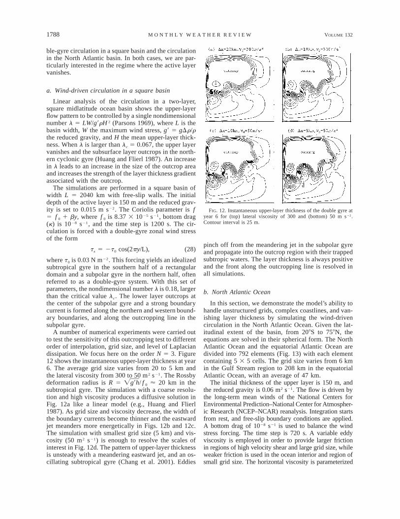
FIG. 12. Instantaneous upper-layer thickness of the double gyre atyear 6 for (top) lateral viscosity of 300 and (bottom) 50 m s22.Contour interval is 25 m.
ble-gyre circulation in a square basin and the circulationin the North Atlantic basin. In both cases, we are par-ticularly interested in the regime where the active layervanishes.
a. Wind-driven circulation in a square basin
Linear analysis of the circulation in a two-layer,square midlatitude ocean basin shows the upper-layerflow pattern to be controlled by a single nondimensionalnumber l 5 LW/g9rH 2 (Parsons 1969), where L is thebasin width, W the maximum wind stress, g9 5 gDr/rthe reduced gravity, and H the mean upper-layer thick-ness. When l is larger than lc 5 0.067, the upper layervanishes and the subsurface layer outcrops in the north-ern cyclonic gyre (Huang and Flierl 1987). An increasein l leads to an increase in the size of the outcrop areaand increases the strength of the layer thickness gradientassociated with the outcrop.
The simulations are performed in a square basin ofwidth L 5 2040 km with free-slip walls. The initialdepth of the active layer is 150 m and the reduced grav-ity is set to 0.015 m s22. The Coriolis parameter is f5 f 0 1 by, where f 0 is 8.37 3 1025 s21, bottom drag(k) is 1028 s21, and the time step is 1200 s. The cir-culation is forced with a double-gyre zonal wind stressof the form
t 5 2t cos(2py/L),x 0 (28)
where t0 is 0.03 N m22. This forcing yields an idealizedsubtropical gyre in the southern half of a rectangulardomain and a subpolar gyre in the northern half, oftenreferred to as a double-gyre system. With this set ofparameters, the nondimensional number l is 0.18, largerthan the critical value lc. The lower layer outcrops atthe center of the subpolar gyre and a strong boundarycurrent is formed along the northern and western bound-ary boundaries, and along the outcropping line in thesubpolar gyre.
A number of numerical experiments were carried outto test the sensitivity of this outcropping test to differentorder of interpolation, grid size, and level of Laplaciandissipation. We focus here on the order N 5 3. Figure12 shows the instantaneous upper-layer thickness at year6. The average grid size varies from 20 to 5 km andthe lateral viscosity from 300 to 50 m2 s21. The Rossbydeformation radius is R 5 / f 0 ø 20 km in theÏg9hsubtropical gyre. The simulation with a coarse resolu-tion and high viscosity produces a diffusive solution inFig. 12a like a linear model (e.g., Huang and Flierl1987). As grid size and viscosity decrease, the width ofthe boundary currents become thinner and the eastwardjet meanders more energetically in Figs. 12b and 12c.The simulation with smallest grid size (5 km) and vis-cosity (50 m2 s21) is enough to resolve the scales ofinterest in Fig. 12d. The pattern of upper-layer thicknessis unsteady with a meandering eastward jet, and an os-cillating subtropical gyre (Chang et al. 2001). Eddies
pinch off from the meandering jet in the subpolar gyreand propagate into the outcrop region with their trappedsubtropic waters. The layer thickness is always positiveand the front along the outcropping line is resolved inall simulations.
b. North Atlantic Ocean
In this section, we demonstrate the model’s ability tohandle unstructured grids, complex coastlines, and van-ishing layer thickness by simulating the wind-drivencirculation in the North Atlantic Ocean. Given the lat-itudinal extent of the basin, from 208S to 758N, theequations are solved in their spherical form. The NorthAtlantic Ocean and the equatorial Atlantic Ocean aredivided into 792 elements (Fig. 13) with each elementcontaining 5 3 5 cells. The grid size varies from 6 kmin the Gulf Stream region to 208 km in the equatorialAtlantic Ocean, with an average of 47 km.
The initial thickness of the upper layer is 150 m, andthe reduced gravity is 0.06 m2 s21. The flow is driven bythe long-term mean winds of the National Centers forEnvironmental Prediction–National Center for Atmospher-ic Research (NCEP–NCAR) reanalysis. Integration startsfrom rest, and free-slip boundary conditions are applied.A bottom drag of 1028 s21 is used to balance the windstress forcing. The time step is 720 s. A variable eddyviscosity is employed in order to provide larger frictionin regions of high velocity shear and large grid size, whileweaker friction is used in the ocean interior and region ofsmall grid size. The horizontal viscosity is parameterized

JULY 2004 1789C H O I E T A L .
FIG. 13. Unstructured elements in the North and equatorial AtlanticOcean. Each element is subdivided into 5 3 5 cells, and the averagegrid spacing is 47 km. The coastline follows the 200-m isobaths.
FIG. 14. Contours of upper-layer thickness in the North AtlanticOcean at year 3. The resting depth is 150 m, and contour interval is20 m. The average grid sizes are (a) 47.0 and (b) 23.5 km.
as n 5 n0 1 2.0DxDy | D | , where n0 is background hor-izontal viscosity, DxDy is the area of the cell, and | D | isthe absolute value of the total deformation of the velocityfield (Smagorinsky 1963; Deardorff 1971):
1/22 2]u ]y ]u ]y
|D | 5 2 1 1 . (29)1 2 1 2[ ]]x ]y ]x ]y
Bleck et al. (1992) used the proportionality constant 2.0,and Griffies and Hallberg (2000) chose the constant 1.0for their simulations. The background horizontal vis-cosity is set to 300 m2 s21.
Figure 14a shows instantaneous contours of upper-layer thickness after 3 yr of simulation from rest. Thereare both a cyclonic subpolar gyre above 508N and ananticyclonic subtropical gyre below 508N. The upperlayer vanishes at the center of the subpolar gyre, south-east of Greenland (Fig. 14a). The East Greenland Cur-rent and the Labrador Current are developed along thenorthwestern boundaries. Another boundary current isevident along the outcropping line about 558N. The lat-itude of the outcropping line depends on the initialchoice of upper-layer thickness. A loop current formsin the Gulf of Mexico and sheds eddies. The Gulf Streamis intensified along the western boundary, and it sepa-rates correctly near Cape Hatteras, North Carolina.
To test sensitivity to grid size, we repeat the simu-lation on a fine grid. Each element in Fig. 13 is dividedinto four elements to obtain the fine-resolution grid. Theaverage grid size becomes 23.5 km and all other pa-rameters are the same. In this fine resolution, the westernboundary currents become thinner and the Gulf Streammeanders after it separates from the coast (Fig. 14b).
The locations of the boundary currents, the outcroppingline, and the gross patterns of circulation are the sameas in the coarse-resolution counterpart.
5. Conclusions and discussion
We have developed a model based on the spectralfinite-volume method to solve the shallow water equa-tions. The geometric flexibility and high accuracy ofthis method are built upon the two-tier grid of globallyunstructured elements and locally structured cells. Nu-merical tests on problems with smooth solution confirmthe high-order convergence rate of the method. Al-though the method can be extended to arbitrarily highorder in N, practical computational and accuracy con-siderations for our applications favor a limit of approx-imately N 5 7.

1790 VOLUME 132M O N T H L Y W E A T H E R R E V I E W
Gibbs oscillations in underresolved simulations, andwhere the solution contains discontinuities, are effec-tively eliminated with the FCT algorithm, as demon-strated in the supercritical channel flow and the reduced-gravity simulations. Experimentation with the applica-tion of FCT to a system of equations indicates that thesynchronous application of the correction factors to allfluxes improves robustness at the expense of increasednumerical dissipation. The compromise of limiting FCTto the continuity equation, while counting on viscousdissipation to damp the momentum equations, seems towork well in our reduced-gravity ocean modeling ex-periments. The model is able to reproduce steep out-cropping, and the circulation exhibits the major oceancurrents and eddies expected.
The computation of second derivatives are not trivialin a high-order finite-volume method, which compli-cates the implementation of viscous operators. Insteadof using the finite-volume approach we used the spectralelement method to calculate the horizontal viscosityterms. All variables are interpolated on the Gauss–Lob-atto–Legendre points and the second derivatives are cal-culated in the weak form (Iskandarani et al. 1995). Thediscontinuous Galerkin method was also tried to cal-culate the horizontal viscous fluxes and it did not im-prove our simulations.
We note that the SFV method in our experience ismore expensive than methods based on variationalmethods like the spectral element method or the dis-continuous Galerkin methods. The reason is the increasein computational cost due to the flux calculations at celledges; these require expensive high-order interpolationto nonstandard collocation points. Operation count isproportional to N 4 in the SFV method and N 3 in vari-ational methods. However, the increased computationalcost is small when considering the relatively low inter-polation order. Furthermore, the ability to use standardTVD schemes developed for other finite-volume meth-ods more than compensates for the extra cost. One ad-ditional mitigating factor is that most calculations areentirely local to an element and can proceed indepen-dently. This makes the method well suited for parallelcomputers. In fact, a parallel version of the model wasbuilt using techniques borrowed from Curchitser et al.(1998).
The performance of the FCT scheme can be improvedby, for example, including a discriminator to distinguishbetween smooth extrema and true discontinuities (Sche-petkin and McWilliams 1998). Another model improve-ment is to change the interpolation order dynamicallyaccording to the evolving solution. Areas where the lim-iters are acting frequently would have a lower-orderinterpolation than where they act more intermittently.These experiments will be pursued in the near future.Our next major goal is to develop a multilayer versionof the present model for application to regional andlarge-scale ocean circulation modeling.
Acknowledgments. This research was supported bythe Office of Naval Research (Grants N00014-00-1-0230, N00014-01-1-0212, and N00014-03-1-0255) andthe National Science Foundation (Grants NSF-0196458,ACI-0196444, and OCE-9730596), as well as by fundsfrom the Institute of Marine and Coastal Sciences, Rut-gers University.
REFERENCES
Alcrudo, F., and P. Garcia-Navarro, 1993: A high-resolution Godunov-type scheme in finite volumes for the 2D shallow-water equa-tions. Int. J. Numer. Methods Fluids, 16, 489–505.
Bleck, R., and D. Boudra, 1986: Wind-driven spin-up in eddy-re-solving ocean models formulated in isopycnic and isobaric co-ordinates. J. Geophys. Res., 91, 7611–7621.
——, C. Rooth, D. Hu, and L. Smith, 1992: Salinity-driven ther-mocline transients in a wind- and thermohaline-forced isopycniccoordinate model of the North Atlantic. J. Phys. Oceanogr., 22,1486–1505.
Boris, J. P., and D. L. Book, 1973: Flux-corrected transport. I: SHAS-TA a fluid transport algorithm that works. J. Comput. Phys., 11,38–69.
Boyd, J. P., 1994: Hyperviscous shock layers and diffusion zones:Monotonicity, spectral viscosity, and pseudospectral methods forvery high order differential equations. J. Sci. Comput., 9, 81–106.
——, 2001: Chebyshev and Fourier Spectral Methods. Dover, 688pp.
Chang, K.-I., M. Ghil, K. Ide, and C. A. Lai, 2001: Transition toaperiodic variability in a wind-driven double-gyre circulationmodel. J. Phys. Oceanogr., 31, 1260–1286.
Chassignet, E. P., and Coauthors, 2000: DAMEE-NAB: The baseexperiments. Dyn. Atmos. Oceans, 32, 155–184.
Chen, C., H. Liu, and R. C. Beardsley, 2003: An unstructured grid,finite volume, three-dimensional, primitive equations oceanmodel: Application to coastal ocean and estuaries. J. Atmos.Oceanic Technol., 20, 159–186.
Curchitser, E. N., M. Iskandarani, and D. B. Haidvogel, 1998: Aspectral element solution of the shallow water equations on mul-tiprocessor computers. J. Atmos. Oceanic Technol., 15, 510–521.
Deardorff, J. W., 1971: On the magnitude of the subgrid scale eddycoefficient. J. Comput. Phys., 7, 120–133.
Durran, D. R., 1999: Numerical Methods for Wave Equations in Geo-physical Fluid Dynamics. Springer-Verlag, 465 pp.
Giannakouros, J., and G. E. Karniadakis, 1992: Spectral element-FCT method for scalar hyperbolic conservation laws. Int. J. Nu-mer. Methods Fluids, 14, 707–727.
——, and ——, 1994: A spectral element–FCT method for the com-pressible Euler equations. J. Comput. Phys., 115, 65–85.
——, D. Sidilkover, and G. E. Karniadakis, 1994: Spectral element–FCT method for the one- and two-dimensional compressible Eu-ler equations. Comput. Methods Appl. Mech. Eng., 116, 113–121.
Godunov, S. K., 1969: A difference scheme for numerical compu-tation of discontinuous solution of hydrodynamics equations.Mat. Sb., 47, 271–306.
Griffies, S., and R. Hallberg, 2000: Biharmonic friction with a Sma-gorinsky-like viscosity for use in large-scale eddy-permittingocean models. Mon. Wea. Rev., 128, 2935–2946.
Haidvogel, D. B., and A. Beckmann, 1999: Numerical Ocean Cir-culation Modeling. Imperial College Press, 318 pp.
Hallberg, R., and P. Rhines, 1996: Buoyancy-driven circulation in anocean basin with isopycnals intersecting the sloping boundary.J. Phys. Oceanogr., 26, 913–940.
Huang, R. X., and G. R. Flierl, 1987: Two-layer models for thethermocline and current structure in subtropical/subpolar gyres.J. Phys. Oceanogr., 17, 872–884.

JULY 2004 1791C H O I E T A L .
Iskandarani, M., D. B. Haidvogel, and J. P. Boyd, 1995: A staggeredspectral element model with application to the oceanic shallowwater equations. Int. J. Numer. Methods Fluids, 20, 393–414.
——, ——, and J. Levin, 2003: A three-dimensional spectral elementmodel for the solution of the hydrostatic primitive equations. J.Comput. Phys., 186, 397–425.
Karniadakis, G. E., and S. J. Sherwin, 1999: Spectral/hp ElementMethods for CFD. Oxford University Press, 408 pp.
Kopriva, D. A., 1996: A conservative staggered grid Chebyshev mul-tidomain method for compressible flows. II: A semi-structuredapproach. J. Comput. Phys., 128, 475–488.
——, and J. H. Kolias, 1996: A conservative staggered grid Che-byshev multidomain method for compressible flows. J. Comput.Phys., 125, 244–261.
LeVeque, R. J., 1992: Numerical Methods for Conservation Laws.Birkhauser Verlag, 214 pp.
Levin, J., M. Iskandarani, and D. Haidvogel, 1997: A spectral filteringprocedure for eddy-resolving simulations with a spectral elementocean model. J. Comput. Phys., 13, 130–154.
Lohner, R., K. Morgan, J. Peraire, and M. Vahdati, 1987: Finite el-ement flux-corrected transport (FEM-FCT) for the Euler andNavier–Stokes equations. Int. J. Numer. Methods Fluids, 7,1093–1109.
Lynch, D. R., and F. E. Werner, 1991: Three-dimensional hydrody-namics on finite elements. Part II: Nonlinear time-stepping mod-el. Int. J. Numer. Methods Fluids, 12, 507–533.
Milliff, R. F., and J. C. McWilliams, 1994: The evolution of boundarypressure in ocean basins. J. Phys. Oceanogr., 24, 1317–1338.
Parsons, A. T., 1969: A two-layer model of Gulf Stream separation.J. Fluid Mech., 39, 511–528.
Schar, C., and P. K. Smolarkiewicz, 1996: A synchronous and iterativeflux-correction formalism for coupled transport equations. J.Comput. Phys., 128, 101–120.
Schepetkin, A. F., and J. C. McWilliams, 1998: Quasi-monotone ad-vection schemes based on explicit locally adaptive dissipation.Mon. Wea. Rev., 126, 1541–1580.
Sidilkover, D., and G. E. Karniadakis, 1993: Non-oscillatory spectralelement chebyshev method for shock wave calculations. J. Com-put. Phys., 107, 10–22.
Smagorinsky, J. S., 1963: General circulation experiments with theprimitive equations. I. The basic experiment. Mon. Wea. Rev.,91, 99–164.
Toro, E. F., 1999: Riemann Solvers and Numerical Methods for FluidDynamics. Springer-Verlag, 624 pp.
——, 2001: Shock-Capturing Methods for Free-Surface ShallowFlows. John Wiley and Sons, 400 pp.
Toth, G., and D. Odstrcil, 1996: Comparison of some flux correctedtransport and total variation diminishing numerical schemes forhydrodynamics and magnetohydrodynamic problems. J. Com-put. Phys., 128, 82–100.
Wang, Z. J., 2002: Spectral (finite) volume method for conservationlaws on unstructured grids: Basic formulation. J. Comput. Phys.,178, 210–251.
——, and Y. Liu, 2002: Spectral (finite) volume method for conser-vation laws on unstructured grids. II: Extension to two-dimen-sional scalar equation. J. Comput. Phys., 179, 665–697.
Willebrand, J., and Coauthors, 2001: Circulation characteristics inthree eddy permitting models of the North Atlantic. Progress inOceanography, Vol. 48, Pergamon Press, 123–161.
Zalesak, S. T., 1979: Fully multidimensional flux-corrected transportalgorithm for fluids. J. Comput. Phys., 31, 335–362.