A Software Communications Architecture Compliant Software...
105
A Software Communications Architecture Compliant Software Defined Radio Implementation A Thesis Presented by Sabri Murat Bi¸cer to The Department of Electrical and Computer Engineering in partial fulfillment of the requirements for the degree of Master of Science in Electrical Engineering in the field of Computer Engineering Northeastern University Boston, Massachusetts June 2002
-
Upload
hoangthien -
Category
Documents
-
view
215 -
download
1
Transcript of A Software Communications Architecture Compliant Software...
A Software Communications Architecture Compliant
Software Defined Radio Implementation
A Thesis Presented
by
Sabri Murat Bicer
to
The Department of Electrical and Computer Engineering
in partial fulfillment of the requirements
for the degree of
Master of Science
in
Electrical Engineering
in the field of
Computer Engineering
Northeastern University
Boston, Massachusetts
June 2002

c© Copyright 2002 by Sabri Murat Bicer
All Rights Reserved
NORTHEASTERN UNIVERSITYGraduate School of Engineering
Thesis Title: A Software Communications Architecture Compliant Software
Defined Radio Implementation.
Author: Sabri Murat Bicer.
Department: Electrical and Computer Engineering.
Approved for Thesis Requirements of the Master of Science Degree
Thesis Advisor: Prof. David Kaeli Date
Thesis Reader: Dr. Jeffrey Smith Date
Thesis Reader: Prof. Karl Lieberherr Date
Department Chair: Prof. Fabrizio Lombardi Date
Graduate School Notified of Acceptance:
Dean: Prof. Yaman Yener Date
Copy Deposited in Library:
Reference Librarian Date
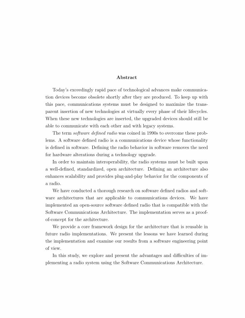
Abstract
Today’s exceedingly rapid pace of technological advances make communica-
tion devices become obsolete shortly after they are produced. To keep up with
this pace, communications systems must be designed to maximize the trans-
parent insertion of new technologies at virtually every phase of their lifecycles.
When these new technologies are inserted, the upgraded devices should still be
able to communicate with each other and with legacy systems.
The term software defined radio was coined in 1990s to overcome these prob-
lems. A software defined radio is a communications device whose functionality
is defined in software. Defining the radio behavior in software removes the need
for hardware alterations during a technology upgrade.
In order to maintain interoperability, the radio systems must be built upon
a well-defined, standardized, open architecture. Defining an architecture also
enhances scalability and provides plug-and-play behavior for the components of
a radio.
We have conducted a thorough research on software defined radios and soft-
ware architectures that are applicable to communications devices. We have
implemented an open-source software defined radio that is compatible with the
Software Communications Architecture. The implementation serves as a proof-
of-concept for the architecture.
We provide a core framework design for the architecture that is reusable in
future radio implementations. We present the lessons we have learned during
the implementation and examine our results from a software engineering point
of view.
In this study, we explore and present the advantages and difficulties of im-
plementing a radio system using the Software Communications Architecture.

Acknowledgements
Through the course of my studies, I have been fortunate to enjoy unwavering
support and encouragement of my parents, Nur and Hilmi Bicer. To them I owe
a debt of gratitude that can scarcely be contained in this acknowledgement.
I am grateful to my advisor, Prof. David Kaeli, for guiding me into the field
of computer architecture and software engineering, as well as helping me expand
my knowledge in all other areas of this research. His guidance in writing this
thesis was indispensable. Most importantly, I am grateful to Dr. Kaeli for giving
me the chance and necessary support that made this research possible. More
than a professor, Dr. Kaeli has been a friend and mentor to me.
I am also grateful to Dr. Jeffrey Smith, for introducing me to the field of
software defined radios and guiding me throughout my research. This thesis
could never have been completed without his excellent guidance and tireless
support. It has been a great pleasure and, in fact, an honor to work with him.
ii

I would like to express my sincere thanks and appreciation to Prof. Karl
Lieberherr and Dr. David Murotake for their valuable comments and ideas.
Many inspiring discussions with them were encouraging and essential for the
progress of my research.
A special acknowledgement is due to Efe Yardımcı who introduced me to the
NUCAR Laboratory and helped me get a foothold in Boston. I would like to
thank him for providing a constant source of encouragement and support, and
for reminding me to relax. His legacy is difficult to live up to.
I gratefully acknowledge the help of Jennifer Black, Pavle Belanovic and
Prateek Jetly in proof-reading this document, in some cases several times.
Thank you for believing in me.
iii

to Mom and Dad...
iv
Contents
1 Introduction 1
1.1 The Problem . . . . . . . . . . . . . . . . . . . . . . . . . . . . 1
1.2 Definitions . . . . . . . . . . . . . . . . . . . . . . . . . . . . . . 3
1.3 Contributions of This Thesis . . . . . . . . . . . . . . . . . . . . 5
1.4 Thesis Organization . . . . . . . . . . . . . . . . . . . . . . . . . 5
2 Background 7
2.1 Software Architectures . . . . . . . . . . . . . . . . . . . . . . . 7
2.1.1 SCA . . . . . . . . . . . . . . . . . . . . . . . . . . . . . 13
2.2 Middleware . . . . . . . . . . . . . . . . . . . . . . . . . . . . . 18
2.2.1 CORBA . . . . . . . . . . . . . . . . . . . . . . . . . . . 23
2.3 Wireless Radio Protocols . . . . . . . . . . . . . . . . . . . . . . 27
2.3.1 SDR . . . . . . . . . . . . . . . . . . . . . . . . . . . . . 34
v
3 An SCA-Compliant SDR Design 39
3.1 Base Application Interfaces . . . . . . . . . . . . . . . . . . . . 41
3.2 Framework Control Interfaces . . . . . . . . . . . . . . . . . . . 46
3.3 Framework Services Interfaces . . . . . . . . . . . . . . . . . . . 55
3.4 The FM3TR Waveform . . . . . . . . . . . . . . . . . . . . . . . 56
4 Implementation 60
5 Results 71
5.1 Client Server Communication Models . . . . . . . . . . . . . . . 71
5.2 Code Reusability . . . . . . . . . . . . . . . . . . . . . . . . . . 77
5.3 The File System . . . . . . . . . . . . . . . . . . . . . . . . . . . 80
5.4 Interoperability . . . . . . . . . . . . . . . . . . . . . . . . . . . 82
6 Conclusions and Future Work 83
Bibliography 88
vi
List of Tables
2.1 Scientific Band Designations. . . . . . . . . . . . . . . . . . . . . 28
2.2 Evolution of Military Radios. . . . . . . . . . . . . . . . . . . . 36
5.1 Timings for Some Operations. . . . . . . . . . . . . . . . . . . . 72
5.2 Binary Sizes of Components. . . . . . . . . . . . . . . . . . . . . 76
5.3 Files Used in the Project. . . . . . . . . . . . . . . . . . . . . . 78
vii
List of Figures
2.1 Relationship between SCA components. . . . . . . . . . . . . . . 18
2.2 Relationship between the SCA and CORBA. . . . . . . . . . . . 19
2.3 Stubs and Skeletons in CORBA. . . . . . . . . . . . . . . . . . . 26
2.4 ORB Communication. . . . . . . . . . . . . . . . . . . . . . . . 27
2.5 Dual-Mode Radio. . . . . . . . . . . . . . . . . . . . . . . . . . 31
3.1 Relationships between SCA CF Interfaces. . . . . . . . . . . . . 41
3.2 Resource Interface UML Diagram. . . . . . . . . . . . . . . . . . 43
3.3 SCA Interfaces Used in Our Radio Design. . . . . . . . . . . . . 45
3.4 Sequence Diagram for DeviceManager Startup. . . . . . . . . . . 51
3.5 Sequence Diagram for Installing a new Application. . . . . . . . 52
3.6 State Transition Diagram for usageState attribute of Device. . . 53
3.7 Collaboration Diagram for ApplicationFactory. . . . . . . . . . . 54
3.8 FM3TR Waveform Application Building Blocks. . . . . . . . . . 57
viii

4.1 Hardware Mapping of the System. . . . . . . . . . . . . . . . . . 68
ix
Chapter 1
Introduction
The term software defined radio refers to reconfigurable or reprogrammable ra-
dios that can show different functionality with the same hardware. Because
the functionality is defined in software, a new technology can easily be imple-
mented in a software radio with a software upgrade. This thesis explores the
implementation of a software defined radio.
1.1 The Problem
Today’s continuously changing technology brings the need to build “future-
proof” radios. If the functions that were formerly carried out by hardware
can be performed by software, new functionality can be deployed on a radio
1
CHAPTER 1. INTRODUCTION 2
by updating the software running on it. Increasing traffic rates, but decreasing
amounts of spectrum requires even more sophisticated signal processing algo-
rithms be deployed on radios. The increase of variable-QoS, multi-component
traffic, requires complex management of resources allocated in the operation of
a user connection. There is a need to deploy a multiplicity of standards within
a single device.
In a software defined radio, multiple waveforms can be implemented in soft-
ware, using the same hardware. One software defined radio can communicate
with many different radios, with only a change in software parameters. This
means interoperability among different military units, emergency units, and
coalition armies. New technologies can be adapted quickly, easily, and for a
much lower cost.
To build radios that are able to support operations in a wide variety of
domains without losing the ability to communicate with each other, an open,
standardized architecture must be defined. By building upon a common, well-
defined, open architecture, radio vendors could improve interoperability by pro-
viding the ability to share waveform software between radios, and reduce devel-
opment time through software reuse. Such an architecture would also facilitate
scalability and technology insertion.
CHAPTER 1. INTRODUCTION 3
In this thesis, we implemented a software radio application using an open
architecture, and investigated the advantages of such an implementation.
1.2 Definitions
This section provides a brief introduction for the key terms used throughout the
text. These terms are discussed in greater detail in chapter 2.
A Software Defined Radio (SDR) is a rencofigurable radio, in which the
functionality is defined in software. In an SDR, the same hardware can be used
to perform different functions at different times. The SDR provides a flexible
radio architecture that allows changing the radio personality in real-time.
The Software Communications Architecture (SCA) is an open architecture
defined by the Joint Tactical Radio System (JTRS) Joint Program Office (JPO).
The SCA has been published to provide a common open architecture that can
be used to build a family of radios across multiple domains. The radios built
upon SCA are interoperable, can use a wide range of frequencies, and enable
technology insertion. The SCA also supports software reusability. The SCA is
used as the underlying architecture in our radio implementation.
The Common Object Request Broker (CORBA) is a middleware defined
by the Object Management Group (OMG). It provides the infrastructure for
CHAPTER 1. INTRODUCTION 4
computer applications developed in different languages and running on different
platforms to work together over a network. The objects in CORBA applications
are defined as interfaces, using OMG’s Interface Definition Language (IDL). The
SCA uses CORBA as its software communication bus, and defines its compo-
nents using IDL.
The Model Driven Architecture (MDA) is another OMG specification that
separates the fundamental logic behind a specification from the specifics of the
particular middleware that implements it. MDA promises rapid inclusion of
emerging technology benefits into existing systems by providing a solid frame-
work that frees system infrastructures to evolve in response to new platforms
while preserving existing technology investments. A complete MDA specifica-
tion consists of a definitive platform independent model (PIM), plus one or
more platform specific models (PSM) and interface definition sets, each describ-
ing how the base model is implemented on a different middleware platform. A
PIM for the SCA is currently under development by the OMG Software Radio
(SWRADIO) Domain Special Interest Group (DSIG). This thesis can serve as
a PSM mapping for the SCA PIM.
CHAPTER 1. INTRODUCTION 5
1.3 Contributions of This Thesis
We make the following contributions in this thesis:
• We develop an open-source reference implementation of the SCA version
2.2.
• We implement a proof-of-concept software radio application using a simple,
low-bandwidth waveform. The design we provide for the radio system can
guide the development of SCA compatible radio systems.
• We provide reusable, open-source software components that can be used
to built up SCA compatible radios.
• We define a PSM mapping of the SCA PIM which in turn can influence
the development efforts of the PIM.
• We propose a minimum SCA definition.
1.4 Thesis Organization
This thesis is presented in six chapters and is organized as follows:
Chapter 2 presents an overview of different software architectures, middle-
ware and wireless applications. It contains a discussion of the model driven
CHAPTER 1. INTRODUCTION 6
architecture, platform independent models and platform specific models and
examines the related work on software radios.
Chapter 3 begins by examining the organization of the software communica-
tions architecture and components used in our implementation. It discusses the
different design ideas, and justifies the methods we have used.
Chapter 4 describes how the design is implemented in our current platform.
It also discusses the difficulties encountered while implementing and testing the
components.
Chapter 5 presents our results from a software engineering point of view.
The amount of reuse is examined, and portability and interoperability issues are
discussed.
Chapter 6 presents our conclusions and summarizes our observations. We
then discuss possible future areas of work.
Chapter 2
Background
2.1 Software Architectures
The foundation of any digital system is the architecture. The term architecture
can refer to software, hardware or a combination of two. In this section, we will
focus on software architectures.
Software architecture is a level of abstraction at which a system is typically
described as a collection of components and their interactions [6]. Components
perform the primary computations of the system. Interactions between com-
ponents include high level communication abstractions such as message passing
and event broadcast.
7
CHAPTER 2. BACKGROUND 8
According to Garlan and Shaw [7], a software architecture includes com-
ponents, connectors and configurations, where components define the locus of
computation, connectors define the interactions between components and con-
figurations define the topology of the components and connectors.
Bass et al. [8], define the software architecture of a program or computing
system as the structure or structures of the system, which comprise software
components, the externally visible properties of those components, and the re-
lationships among them. The structure should represent an abstract view of
the system without implying any implementation details. A software architec-
ture also defines various static and dynamic relationships between those compo-
nents [8, 9].
A software architecture should represent a high-level view of the system re-
vealing the structure, but it should hide all implementation details [10]. Specif-
ically, it should reveal attributes such as responsibilites of the constituents of
the architecture, distribution and deployment. It should also realize use case
scenarios with appropriate models and present both a logical or conceptual view
and a deployment view of the software [11].
CHAPTER 2. BACKGROUND 9
A software architecture has different goals for different groups. For the sys-
tems engineer, a software architecture brings consistency, requirements traca-
bility, and trade-off and completeness analysis whereas for the developer, it
provides sufficient detail for design and interoperability with legacy systems. It
establishes a reference for assembling components and guides the developer for
software modification. The software architecture provides consistency with use
case scenarios, reliability and interoperability analysis and project scheduling
for the end user.
There are many different software architectures that are related to commu-
nications in one way or another. In this section, we examined some of these
architecture. While discussing these architectures, we tried to choose examples
that are open, well documented and covering a wide range of domains. The list
of architectures discussed here is not inclusive.
B. Hayes-Roth et al. , present a domain-specific software architecture (DSSA)
that is developed for a large application domain of adaptive intelligent systems
(AISs) in [12]. Their architecture provides an AIS reference architecture de-
signed to meet the functional requirements shared by applications in this domain
and an application configuration method for selecting relevant components from
CHAPTER 2. BACKGROUND 10
a library and automatically configuring instances of those components in an in-
stance of the architecture. Another software architecture example is the Virtual
Distributed Computing Environment (VDCE) [13]. VDCE provides a problem-
solving environment for high-performance distributed computing over wide area
networks by delivering well-defined library functions. C. Ermel et al., suggests
a two-level approach to visually describe software architectures and their evo-
lution [14]. One visual modeling formalism is used to describe the architecture
level while another is used to model the behavior of each component.
The Aerospace Corporation Space Systems Group developed a reference ar-
chitecture for the Standard Satellite Control Segment (SSCS) of the Satellite
Control Network [15, 16]. The software architure of the system consists of two
layers. The inner layer, System Services, includes (1) the Operating System, (2)
data and database management, file archiving, and configuration management
services, (3) middleware, including message passing, timing, security services,
and support for all platforms across the Local Area Network (LAN), (4) the
Human Computer Interface (HCI), and (5) a DSS consisting of stored proce-
dures and an expert system inference engine. The next layer consists of SSCS
Tracking, Telemetry and Command (TT&C) applications used by all ground
systems, mission-unique applications, and support applications.
CHAPTER 2. BACKGROUND 11
Washington University Computer Science Department has a project called
ArchJava. ArchJava is an extension to Java that seamlessly unifies software
arhitecture with implementation, ensuring that the implementation conforms
to architectural constraints [17]. ArchJava unifies architectural structure and
implementation in one language, allowing flexible implementation techniques,
ensuring traceability between architecture and code, and supporting the co-
evolution of architecture and implementation. It guarantees communication
integrity between an architecture and its implementation, even in the presence
of advanced architectural features like run time component creation and con-
nection.
Our project uses the SCA to implement the software defined radio. SCA is
a software architecture specifically designed for communications devices. The
architectures described above are not designed for communication systems, thus
they do not provide interfaces directly mappable to radio components. The
SSCS software architecture has similar interfaces but it is a very heavy-weight
architecture for a radio system. SCA is an open architecture and it is applicable
across a wide range of communications domains. It supports interoperability
through well defined interfaces. The reusability potential for the software com-
ponents of an SCA implementation is very high. Our project serves as a reference
CHAPTER 2. BACKGROUND 12
implementation of this architecture. ArchJava is currently not applicable to our
project as our implementation is in C++. Future versions implemented in Java
may employ ArchJava, to ensure SCA conformance.
Another reason for choosing SCA was its plug-and-play support. If an ar-
chitecture supports plug-and-play, then the design rules have been crafted so
that hardware and software modules from different suppliers will work together
when plugged into an existing system [5]. The SCA defines the partioning of
functions into groups, which may subsequently be allocated to components.
MDA [18] defines a higher level of abstraction for software architectures. It
is a new way of writing specifications and developing applications, based on a
PIM. A PIM is the modelling of a system using methods that do not depend
on specific platform. It is an abstract way of modelling. A complete MDA
specification consists of a definitive platform-independent base Unified Modelling
Language (UML) model, plus one or more platform-specific models (PSM). A
PSM is the mapping of a PIM to a specific platform. Many different PSMs
can be instantiated from a single PIM. MDA development focuses first on the
functionality and behavior of a distributed application or system, undistorted
by details of the technology or technologies in which it will be implemented [19].
It seperates the fundamental logic behind a specification from the specifics of
CHAPTER 2. BACKGROUND 13
the particular middleware that implements it. With MDA, it is not necessary
to repeat the process of modelling an application or system’s functionality and
behavior, each time a new technology comes along. The OMG SWRADIO DSIG
is currently working on the development of a PIM for the SCA. In order to have
a complete MDA specification, a PIM must be mapped to one or more platform
by defining PSMs. Our project can be used as a PSM for the software radio
MDA. Canadian Research Center (CRC) is working on a project called SCARI
[20], which can also serve as a PSM targeting a different platform.
The following subsection discusses SCA in detail.
2.1.1 SCA
When the JTRS JPO was established to acquire a family of affordable, high-
capacity, tactical radio systems that can provide interoperable wireless mobile
network services, the need for an open architecture emerged. By building upon
a common open architecture, JTRS can improve interoperability by providing
the ability to share waveform software between radios and reduce development
and deployment costs. In view of its potential applicability across a wide range
of communications domains, JTRS JPO named this architecture the Software
Communications Architecture [2, 3, 4].
CHAPTER 2. BACKGROUND 14
The JTRS JPO states that the SCA has been published to meet the following
goals [36]:
Common Open Architecture: The use of an open, standardized architecture
has the advantages of promoting competition, interoperability, technology
insertion, quick upgrades, software reuse, and scalability.
Multiple Domains: The JTRS family of radios must be able to support op-
erations in a wide variety of domains, including airborne, fixed, maritime,
vehicular, dismounted and handheld.
Multiple Bands: A JTRS radio can replace a number of radios that use a wide
range of frequencies, and it can interoperate with them.
Compatibility: JTRS radios must be able to communicate with legacy systems
to minimize the impact of platform integration.
Upgrades: The JTRS architecture must enable technology insertion, so that
new technologies can be incorporated to improve performance, and to build
future-proof radios.
Security: Security is a very important aspect of military radios. The archi-
tecture should provide the foundation to solve issues like programmable
crytographic capability, certificate management, user identification and

CHAPTER 2. BACKGROUND 15
authentication, key management, and multiple independent levels of clas-
sification.
Networking: The JTRS radios should support legacy network protocols, for
the purpose of seamless integration. The architecture should also support
wideband networking capabilities for voice, data and video.
Software Reusability: As with any other software architecture, the JTRS ar-
chitecture should allow for the maximum possible reuse of software com-
ponents. The components should support plug-n-play behavior with wave-
forms being portable from one implementation to the next.
The SCA defines an Operating Environment (OE) that will be used by JTRS
radios. It also specifies the services and interfaces that the applications use from
the environment. The interfaces are defined by using the CORBA IDL, and
graphical representations are made by using UML [1].
The OE consists of a Core Framework (CF), a CORBA middleware and a
POSIX-based Operating System (OS). The OS running the SCA must provide
services and interfaces that are defined as mandatory in the Application Environ-
ment Profile (AEP) of the SCA. The CF describes the interfaces, their purposes
and their operations. It provides an abstraction of the underlying software and
hardware layers for software application developers. An SCA compatible system
CHAPTER 2. BACKGROUND 16
must implement these interfaces. The interfaces are grouped as Base Application
Interfaces, Framework Control Interfaces and Framework Services Interfaces.
The Base Application Interfaces are used by the application layer. They
provide the basic building blocks of an application. The interfaces in this group
are: Port, LifeCycle, TestableObject, PropertySet, PortSupplier, ResourceFac-
tory and Resource.
The Framework Control Interfaces provide the control of the system. The ap-
plication layer can reach the OS through these control interfaces. The interfaces
in this group are: Application, ApplicationFactory, DomainManager, Device,
LoadableDevice, ExecutableDevice, AggragateDevice and DeviceManager.
The Framework Services Interfaces provide the system services. These inter-
faces support both core and none-core applications. They include: File, FileSys-
tem, FileManager and Timer.
The CF uses a Domain Profile to describe the components in the system.
The Domain Profile is a set of XML files that describe the identity, capabili-
ties, properties, inter-dependencies, and location of the hardware devices and
software components that make up the system [2]. The software component
characteristics are contained in the Software Package Descriptor (SPD), Soft-
ware Component Descriptor (SCD) and Software Assembly Descriptor (SAD).
CHAPTER 2. BACKGROUND 17
The hardware device characteristics are stored in the Device Package Descriptor
(DPD) and Device Configuration Descriptor (DCD). The Properties Descriptor
contains information about the properties of a hardware device or software com-
ponent. The Profile Descriptor contains an absolute file name for either a Device
Configuration Descriptor, a Software Package Descriptor or a Software Assem-
bly Descriptor. Finally, the DomainManager Configuration Descriptor (DMD)
contains the configuration information for the DomainManager.
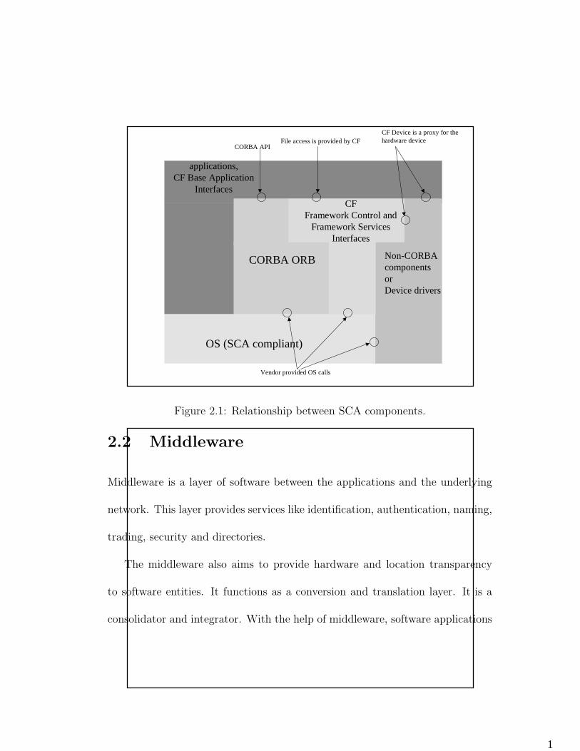
Although the SCA uses the CORBA middleware for its software bus, the
application layer can reach the OS by other means. CORBA adapters can be
used to wrap the legacy software components. Figure 2.1 shows the relationship
between the AEP, the application and the OE.
Our project implements the SCA CF, and uses it to run a waveform appli-
cation, namely Future Multiband Multimode Modular Tactical Radio (FM3TR).
The waveform serves as a proof-of-concept, and proves that any waveform can
be run on top of our SCA implementation, provided that the necessary hardware
exists in the system.
CHAPTER 2. BACKGROUND 18
1
Non-CORBA componentsorDevice drivers
OS (SCA compliant)
CORBA ORB
CFFramework Control and
Framework Services Interfaces
CORBA APIFile access is provided by CF
applications,CF Base Application
Interfaces
Vendor provided OS calls
CF Device is a proxy for the hardware device
Figure 2.1: Relationship between SCA components.
2.2 Middleware
Middleware is a layer of software between the applications and the underlying
network. This layer provides services like identification, authentication, naming,
trading, security and directories.
The middleware also aims to provide hardware and location transparency
to software entities. It functions as a conversion and translation layer. It is a
consolidator and integrator. With the help of middleware, software applications
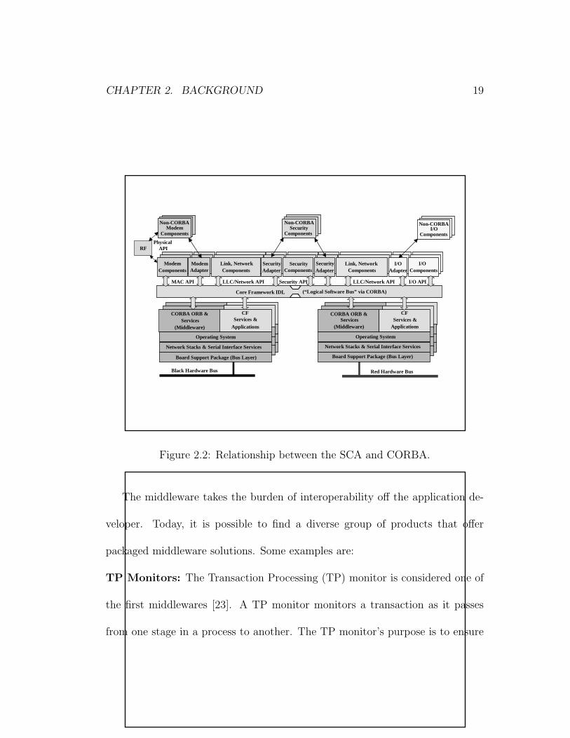
CHAPTER 2. BACKGROUND 19
running on different platforms can communicate transparently. Figure 2.2 shows
the relation between a software architecture and a middleware.
1
Red Hardware Bus
CFServices &
Applications
CORBA ORB &Services
(Middleware)
Network Stacks & Ser ial I nter face Services
Board Support Package (Bus Layer)
Black Hardware Bus
CFServices &
Applications
CORBA ORB &Services
(Middleware)
Network Stacks & Ser ial I nter face Services
Board Support Package (Bus Layer)
Operating System
Core Framework IDL
Non-CORBAModem
Components
Non-CORBASecur ity
Components
Non-CORBAI /O
Components
RF
ModemComponents
L ink, NetworkComponents
Secur ityComponents
ModemAdapter
Secur ityAdapter
Secur ityAdapter
I /OAdapter
I /OComponents
MAC API LLC/Network API LLC/Network API
L ink, NetworkComponents
Secur ity API
Operating System
Physical API
I /O API
(“ Logical Software Bus” via CORBA)
Figure 2.2: Relationship between the SCA and CORBA.
The middleware takes the burden of interoperability off the application de-
veloper. Today, it is possible to find a diverse group of products that offer
packaged middleware solutions. Some examples are:
TP Monitors: The Transaction Processing (TP) monitor is considered one of
the first middlewares [23]. A TP monitor monitors a transaction as it passes
from one stage in a process to another. The TP monitor’s purpose is to ensure
CHAPTER 2. BACKGROUND 20
that the transaction processes completely or, if an error occurs, to take appro-
priate actions. Sitting between the requesting client program and the databases,
it ensures that all databases are updated properly.
TP monitors are especially important in three-tier architectures that em-
ploy load balancing because a transaction may be forwarded to any of several
servers [22]. In fact, many TP monitors handle all of the load balancing oper-
ations, forwarding transactions to different servers based on their availability.
The advantages of using TP monitors also include increased system robustness
and improved throughput.
IBM’s CICS and Encina and BEA’s Top End and Tuxedo are examples of
Transaction Processing Monitors.
Messaging Middleware: Basic message oriented middleware provides con-
nectionless, asynchronous transactional message store-and-forward capability.
It is a common interface and transport between applications. It can serve as
the core of a message broker. Messaging middleware provides an interface be-
tween applications, allowing them to send data back and forth to each other
asynchronously.
A messaging middleware is very similar to email messaging, but its purpose
is to exchange data between applications. It can also contain logic that changes
CHAPTER 2. BACKGROUND 21
the format of the data and routes to appropriate destinations. Data sent by
an application can be stored in a queue, and when the destination becomes
available, it can be forwarded to the destination. Without such a common
message transport and queueing system, each application must ensure that data
sent is received properly. As the applications evolve, this can create a large
programming burden. Once an enterprise conforms to a common messaging
interface, future connections between applications can be easily developed.
Some examples of messaging middleware are BEA System’s MessageQ, IBM’s
MQSeries, Microsoft’s MSMQ and Oracle’s Advanced Queueing.
Distributed Processing: Distributed processing is based on component model
programming. Applications are designed as assemblies of components, and each
component can run on a different part of the network [21]. The components are
usually implemented as objects. Distributed processing differs from messaging
middleware in that, it causes processes to be executed in real time rather than
by sending data.
The most common distributed object systems are OMG’s CORBA, Mi-
crosoft’s Distributed Component Object Model (DCOM) and Sun’s Enterprise
Java Beans (EJB).
CORBA is an architecture and infrastructure that computer applications
CHAPTER 2. BACKGROUND 22
use to work together over networks [24]. A CORBA-based program from any
vendor, on almost any computer, operating system, programming language, or
network, can interoperate with a CORBA-based program from the same or
another vendor on almost any other computer, operating system, programming
language or network.
DCOM is a protocol that enables software components to communicate di-
rectly over a network in a reliable, secure, and efficient manner. Any COM-based
application can be used in DCOM, and the components can be running on dif-
ferent computers, as long as they are part of the same network. The network
can be a LAN, a WAN or even the Internet.
EJB provides automatic support for middleware services like transactions,
database connectivity, network efficiency and security. This helps the application
developer by reducing the level of complexity of the middleware development.
Any Java component can be used in an EJB system.
Database Middleware: A database middleware provides a common interface
for the clients to query multiple distributed database servers. The middleware
can have a distributed architecture or a hub-and-spoke architecture.
Some examples are JSBD, an XML oriented scripting language, based on
JavaScript and IBM’s DB2 Universal Database, a multimedia, Web-enabled
CHAPTER 2. BACKGROUND 23
database for decision support, data warehousing and data mining.
Application Server Middleware: An application server is designed to help
make it easier for developers to isolate the business logic in their projects. They
make use of components to create three-tier applications. Many application
servers also offer services such as tranaction management and load balancing.
IBM’s WebSphere, Oracle’s Oracle 9, Apple’s WebObjects are a few examples
of application servers.
2.2.1 CORBA
Our project uses CORBA as the underlying middleware. CORBA has been
chosen as the middleware layer of the Software Communications Architecture,
because of the wide commercial availability of CORBA products and its indus-
try acceptance. Distributed processing is a fundamental aspect of the JTRS
system architecture. CORBA is used to provide a cross-platform middleware
service that simplifies standardized client/server operations in this distributed
environment by hiding the actual communication mechanisms under an Object
Request Broker software bus [24, 25].
CORBA is the Object Management Group’s open architecture that provides
the infrastructure for computer applications to work together over a network.
CHAPTER 2. BACKGROUND 24
A CORBA-based application written in almost any language and running on
almost any platform can interoperate with another CORBA-based application
written in a different language and running on a different platform. CORBA
is mostly used in large enterprise systems because of its ability to integrate
machines from different vendors easily. It is also used frequently in servers that
need to handle large number of clients at high hit rates securely, and reliably [19].
CORBA applications are composed of objects that encapsulate data and
functionality. These objects are small individual units of running software that
usually represent something in real life. Objects are the instances of a type, and
a typical application will have many instances of a type. These instances all
have the same functionality, but the data they contain differs. A good example
is an e-commerce site that assigns a shopping cart object to every customer. All
the carts will have the functionality to add and remove items, but the items in
the cart will be different for each customer.
Each object in a CORBA application is defined as an interface, using OMG’s
IDL. The interface is the syntax part of the contract that the server object
offers to the clients that invoke it. Any client that wants to invoke an operation
on the object must use this IDL interface to specify the operation it wants
to perform, and to marshal the arguments that it sends. When the invocation
CHAPTER 2. BACKGROUND 25
reaches the target object, the same interface definition is used there to unmarshal
the arguments so that the object can perform the requested operation with them.
The interface definition is then used to marshal the results for their trip back,
and to unmarshal them when they reach their destination [19].
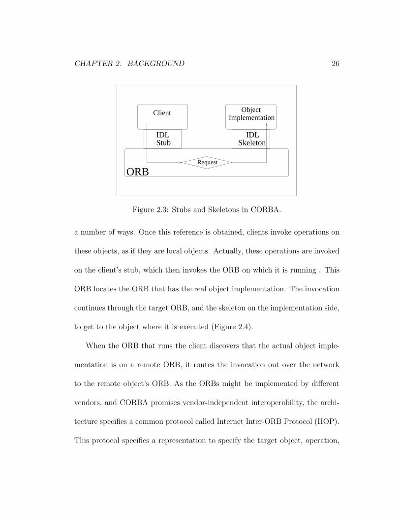
The transparency and interoperability provided by CORBA is enabled by
IDL. IDL separates the interface from the implementation. There is a very
strict interface definition for every CORBA object. This interface is advertised
throughout the system [26]. In contrast, the implementation of the objects
are opaque. The object’s running code and its data is hidden from the rest
of the system with a boundary that the clients cannot pass. Clients can only
reach the objects through their advertised interfaces. An IDL compiler compiles
the given IDL into client stubs and object skeletons. The stubs and skeletons
act as proxies for clients and servers, and they run on top of Object Request
Brokers (ORB). Figure 2.3 shows this configuration. The strict definitions of
the interfaces provides the possibility for the stubs and skeletons mesh together,
even if they are written in different languages, and running on different platforms
and on different ORBs.
Clients reach objects by using object references. In CORBA, every object
has a unique object reference, and this reference can be obtained by a client in
CHAPTER 2. BACKGROUND 26
ORBRequest
SkeletonIDLIDL
Stub
ObjectImplementation
Client
Figure 2.3: Stubs and Skeletons in CORBA.
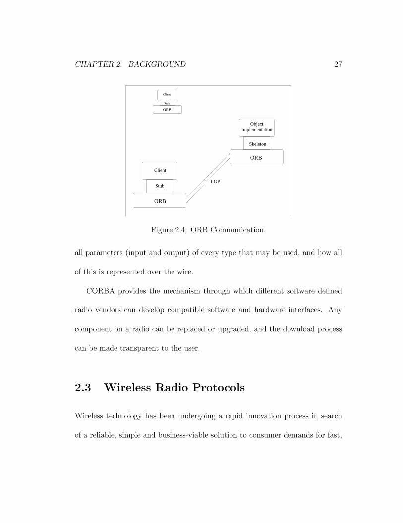
a number of ways. Once this reference is obtained, clients invoke operations on
these objects, as if they are local objects. Actually, these operations are invoked
on the client’s stub, which then invokes the ORB on which it is running . This
ORB locates the ORB that has the real object implementation. The invocation
continues through the target ORB, and the skeleton on the implementation side,
to get to the object where it is executed (Figure 2.4).
When the ORB that runs the client discovers that the actual object imple-
mentation is on a remote ORB, it routes the invocation out over the network
to the remote object’s ORB. As the ORBs might be implemented by different
vendors, and CORBA promises vendor-independent interoperability, the archi-
tecture specifies a common protocol called Internet Inter-ORB Protocol (IIOP).
This protocol specifies a representation to specify the target object, operation,
CHAPTER 2. BACKGROUND 27
Client
Skeleton
ObjectImplementation
ORB
ORB
Stub
ORB
Stub
Client
IIOP
Figure 2.4: ORB Communication.
all parameters (input and output) of every type that may be used, and how all
of this is represented over the wire.
CORBA provides the mechanism through which different software defined
radio vendors can develop compatible software and hardware interfaces. Any
component on a radio can be replaced or upgraded, and the download process
can be made transparent to the user.
2.3 Wireless Radio Protocols
Wireless technology has been undergoing a rapid innovation process in search
of a reliable, simple and business-viable solution to consumer demands for fast,
CHAPTER 2. BACKGROUND 28
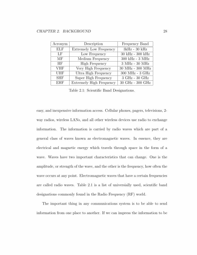
Acronym Description Frequency Band
ELF Extremely Low Frequency 3kHz - 30 kHzLF Low Frequency 30 kHz - 300 kHzMF Medium Frequency 300 kHz - 3 MHzHF High Frequency 3 MHz - 30 MHz
VHF Very High Frequency 30 MHz - 300 MHzUHF Ultra High Frequency 300 MHz - 3 GHzSHF Super High Frequency 3 GHz - 30 GHzEHF Extremely High Frequency 30 GHz - 300 GHz
Table 2.1: Scientific Band Designations.
easy, and inexpensive information access. Cellular phones, pagers, televisions, 2-
way radios, wireless LANs, and all other wireless devices use radio to exchange
information. The information is carried by radio waves which are part of a
general class of waves known as electromagnetic waves. In essence, they are
electrical and magnetic energy which travels through space in the form of a
wave. Waves have two important characteristics that can change. One is the
amplitude, or strength of the wave, and the other is the frequency, how often the
wave occurs at any point. Electromagnetic waves that have a certain frequencies
are called radio waves. Table 2.1 is a list of universially used, scientific band
designations commonly found in the Radio Frequency (RF) world.
The important thing in any communications system is to be able to send
information from one place to another. If we can impress the information to be
CHAPTER 2. BACKGROUND 29
sent on a radio wave in such a way that it can be recovered at the other end, we
can build a communication system. The process of impressing the information
is known as modulation. In order to modulate a radio wave, we have to change
either or both of the two basic characteristics of the wave: the amplitude and
the frequency. Amplitude modulation, AM, means changing the amplitude of a
wave in a way corresponding to the information we are trying to send. Instead
of modulating the amplitude, if we change the frequency of the signal, the re-
sulting modulation is called frequency modulation, FM. There are other types of
modulation techniques that are variations of AM and FM. These include Single
Sideband (SSB), Double Sideband (DSB), Vestigial Sideband(VSB), Frequency
Shift Keying (FSK), Gaussian Minimum Shift Keying (GMSK) and others.
Radios:
Radios are the most common of the wireless communications device in use
today. A radio performs a variety of functions in the process of converting voice
or data information to and from an RF signal. These functions include process-
ing the analog RF signal, waveform modulation/demodulation and processing
of the baseband signal.
The processing of the analog RF signal consists of amplification/deamplification,
converting to/from Intermediate Frequencies, RF upconversion/downconversion
CHAPTER 2. BACKGROUND 30
and noise cancelling. Waveform modulation/demodulation depends on the wave-
forms used in that radio. Our project uses the FM3TR waveform. This part
generally includes error correction and interleaving of the signal. The baseband
signal processing part adds the networking protocols and routes the signal to
the output devices [3, 1].
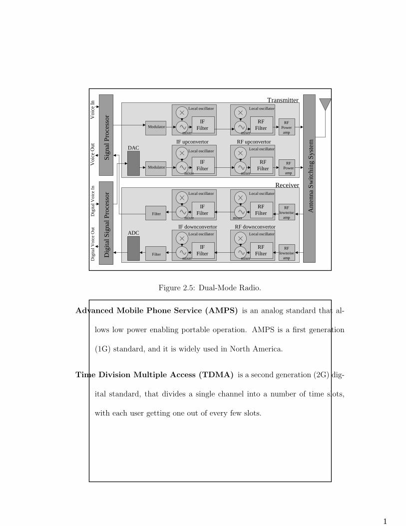
Analog radios perform these functions on analog signals. Using analog signal
processors and heterodyne filters, the analog signal is processed at different
frequencies by a chain of analog functional blocks. Digital radios transform
the analog radio signal to a digital signal at some point in the chain with the
help of an analog-to-digital convertor (ADC), and processes the signal using
digital signal processors (DSP). The digitally processed signal is converted back
to analog by a digital-to-analog convertor (DAC) and transmitted through the
antenna. Figure 2.5 shows the functional blocks in a dual-mode radio, that has
both analog and digital processing [27].
Radio is the backbone of the wireless industry. It forms the basis of all the
mobile and portable communications systems we use today.
Cellular Phones:
Just like radios, cellular phones have also two basic types: analog and digital.
Cellular phones use various standards to communicate. Some examples are:
CHAPTER 2. BACKGROUND 31
1
Sign
al P
roce
ssor
RFPoweramp
Modulator
IF upconvertor
IFFilter
Local oscillator
DACRF upconvertor
RFFilter
Local oscillatorD
igita
l Sig
nal P
roce
ssor
Ant
enna
Sw
itchi
ng S
yste
m
IFFilter
RFFilter
Local oscillatorLocal oscillator
Voi
ce I
nD
igita
l Voi
ce O
utD
igita
l Voi
ce I
nV
oice
Out
IFFilter
IFFilter
RFFilter
RFFilter
Local oscillator
Local oscillator Local oscillator
Local oscillator
RF downconvertorIF downconvertor
mixer
mixer
mixer
mixer
mixer
mixer
mixer mixer
RFlownoise
amp
RFPoweramp
RFlownoise
amp
Modulator
Filter
Filter
ADC
Transmitter
Receiver
Figure 2.5: Dual-Mode Radio.
Advanced Mobile Phone Service (AMPS) is an analog standard that al-
lows low power enabling portable operation. AMPS is a first generation
(1G) standard, and it is widely used in North America.
Time Division Multiple Access (TDMA) is a second generation (2G) dig-
ital standard, that divides a single channel into a number of time slots,
with each user getting one out of every few slots.
CHAPTER 2. BACKGROUND 32
Code Division Multiple Access (CDMA) is a 2G spread spectrum tech-
nology. Spread spectrum means spreading the information contained in a
particular signal of interest over a much greater bandwidth than the orig-
inal signal. Because of the wide bandwidth of a spread spectrum signal, it
is very difficult to jam, interfere with or identify.
Global System for Mobile Communications (GSM) is the world’s lead-
ing and fastest growing mobile standard, that spans over 174 countries.
The signal coding is very similar to TDMA. User authentication is pro-
vided by Subscriber Identity Module (SIM) cards. By inserting the SIM
card into any GSM phone, the user is able to receive calls at that phone,
make calls from that phone or receive other subscribed services.
Wideband Code Division Multiple Access (WCDMA) is a third gener-
ation (3G) standard that spread users information bits over an artificially
broadened bandwidth, by multiplying them with a pseudo-random bit
stream running several times as fast.
Enhanced Data rates for GSM Evolution (EDGE) is a 3G member of the
GSM family. EDGE promises to deliver further enhancements in data ca-
pability over the core GSM. This will achieve the delivery of advanced
CHAPTER 2. BACKGROUND 33
mobile services such as the downloading of video and music clips, full
multimedia messaging, high-speed color internet access and e-mail on the
move.
Universal Mobile Telecommunications System (UMTS) is one of the ma-
jor new 3G mobile communications systems being developed within the
framework defined by the International Telecommunication Union (ITU).
UMTS builds on the capability of today’s mobile technologies by providing
increased capacity, data capability and a greater range of services using an
innovative radio access scheme and an enhanced, evolving core network.
All of these systems require different sets of terminals and base stations, and
they are incompatible with each other. An SDR terminal can use any of these
technologies, provided that it has the necessary software. If a new standard is
developed, or if the user wants to switch to a system that is not present on the
handset, the new software can be downloaded on air. SDR base stations take
the burden of replacing the base station throughout the entire country off the
system providers, by dynamically updating themselves.
CHAPTER 2. BACKGROUND 34
2.3.1 SDR
A software defined radio makes the main characteristics of a communication
device reconfigurable with software rather than with hardware alterations. The
waveform modulation/demodulation functions are defined in software. Software
defined technology offers advantages such as improvements or enhancements
without altering the radio hardware, terminals that can cope with the unpre-
dictable dynamic characteristics of highly variable wireless links, efficient use
of radio spectrum and power, and many others. The users can use relatively
generic hardware, and customize it to their needs by choosing software that fits
their specific application [27, 5].
The improvements in DSP and ADC technologies facilitated the shift to
software defined radios. Modem functions can be implemented in software with
today’s high speed DSPs and General Purpose Processors (GPPs). The low
power requirements of the processors enables them to be used in hand termi-
nals. The increased dynamic operating ranges and higher conversion rates of
modern ADCs enables digital processing at higher bands. The improvements in
middleware technologies permit software functionality to be independent of the
underlying hardware [28, 27].
CHAPTER 2. BACKGROUND 35
One of the first software radios was the US Air Force’s Integrated Commu-
nications Navigation and Identification Avionics (ICNIA) system, which was
developed in the late 1970’s. The system used a DSP-based modem, that is
reprogrammable for different platforms. ICNIA’s technology has been the foun-
dation for many other military radios. In late 1980’s, GEC developed the first
Programmable Digital Radio (PDR) described in the literature [39]. The radio
composed of a black (encrypted) side that employs a low-speed black inter-
connect bus, a programmable message processor, that implements INFOSEC
(information security) and the interconnection of black and red side, and a red
(unencrypted) side that includes a CPU and I/O processor and the power sup-
plies. In the 1990’s, the ITT Corporation developed a digital radio, that is
very similar to GEC’s PDR in terms of high level components . The black side
consists of RF, modem and waveform processor. The modem and waveform
processing is performed by an Intel 486 processor. The modem also uses FPGA
components for hardware intensive computations.
SPEAKeasy is a joint Department of Defense and industry program initiated
to develop a software programmable radio operating in the range from 2 MHz to
2 GHz, employing waveforms selected from memory, or downloaded from disk,
or reprogrammed over the air [29]. It has a fully programmable waveform and
CHAPTER 2. BACKGROUND 36
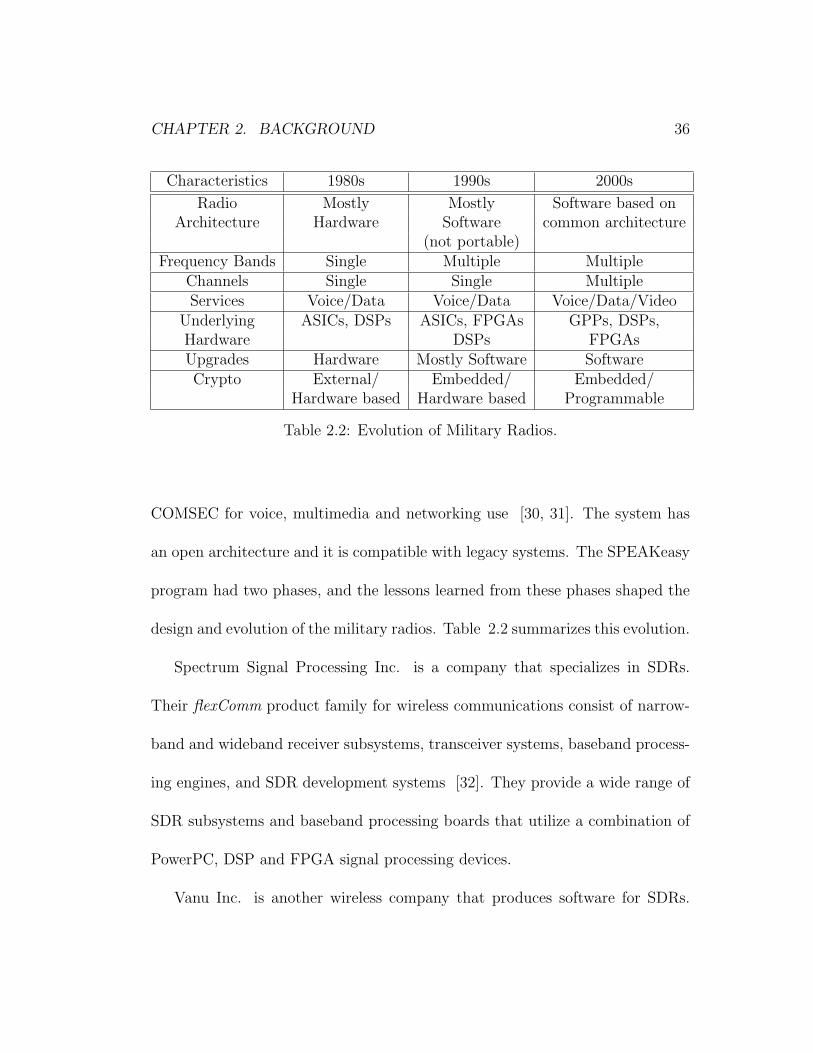
Characteristics 1980s 1990s 2000s
Radio Mostly Mostly Software based onArchitecture Hardware Software common architecture
(not portable)Frequency Bands Single Multiple Multiple
Channels Single Single MultipleServices Voice/Data Voice/Data Voice/Data/Video
Underlying ASICs, DSPs ASICs, FPGAs GPPs, DSPs,Hardware DSPs FPGAsUpgrades Hardware Mostly Software SoftwareCrypto External/ Embedded/ Embedded/
Hardware based Hardware based Programmable
Table 2.2: Evolution of Military Radios.
COMSEC for voice, multimedia and networking use [30, 31]. The system has
an open architecture and it is compatible with legacy systems. The SPEAKeasy
program had two phases, and the lessons learned from these phases shaped the
design and evolution of the military radios. Table 2.2 summarizes this evolution.
Spectrum Signal Processing Inc. is a company that specializes in SDRs.
Their flexComm product family for wireless communications consist of narrow-
band and wideband receiver subsystems, transceiver systems, baseband process-
ing engines, and SDR development systems [32]. They provide a wide range of
SDR subsystems and baseband processing boards that utilize a combination of
PowerPC, DSP and FPGA signal processing devices.
Vanu Inc. is another wireless company that produces software for SDRs.
CHAPTER 2. BACKGROUND 37
They define their own software radio architecture which consists of three hard-
ware layers, an operating system layer and two stacks of application level com-
ponents. They also provide waveform software for waveforms such as AMPS,
TDMA and GSM [33, 34].
GNU Free Software Foundation (FSF) also has an on-going open-source SDR
project. GNU Radio [35] is a collection of software that when combined with
minimal hardware, allows the construction of radios where the actual waveforms
transmitted and received are defined by software. The project development is
open to anybody who wants to contribute.
The difference between a digital radio and an SDR is that a digital radio
is not reconfigurable. Although a digital radio has software running on it, the
functionality of the components cannot be changed on air. New technology
insertion is not available, either.
Our SDR implementation uses the FM3TR waveform, which is a real-time,
digital, frequency hopping multi-national communications waveform developed
by a joint committee of four countries - France, Germany, the United Kingdom
and the United States [37]. The waveform was first used by the Air Force Re-
search Laboratory along with the Rome Research Corporation to develop a new
waveform software that would run on the SPEAKeasy Phase I system [38]. The

CHAPTER 2. BACKGROUND 38
FM3TR waveform is used on our radio system as a proof-of-concept, because it
is a relatively simple waveform that does not require a fast transportation layer,
or intensive CPU processing. Any waveform can be replaced with the current
waveform, using SCA CF Interfaces. These issues are discussed in chapter 5.
Chapter 3
An SCA-Compliant SDR Design
As stated in chapter 2, the SCA is designed to be an open, standardized architec-
ture providing interoperability, technology insertion, quick upgrade capability,
software reuse and scalability. A software engineer should keep these key issues
in mind, while designing the software structure of an SCA compliant software
radio.
CORBA is the interoperability backbone of the SCA specification. Our de-
sign makes efficient use of CORBA in every possible situation, and does not
use any ORB-dependent features to be completely compatible with all CORBA
compliant ORBs. No assumptions are made about the locations of the software
39
CHAPTER 3. AN SCA-COMPLIANT SDR DESIGN 40
components, except for the object factories. (The reasons for location depen-
dency in object factories are discussed in the following sections.)
Software reuse is another very important aspect of our design. Each new
waveform on the radio system is deployed as a new application. The specific
waveform application inherits the SCA CF Application, which has the generic
functions implemented. The waveform specific behavior can be implemented by
function overloading. All waveforms can use the CF services like the FileSystem,
which is another factor increasing reusability. Software reuse is discussed in
detail in the results chapter.
Scalability is provided by software component assemblies. A waveform ap-
plication creates a CF Resource for each functional unit, connects these re-
sources to each other using CF Ports, and deploys these resources on CF De-
vices. New functionality can be added easily to an existing system by creating
a new Resource, and connecting it to the necessary resources. When a new
hardware device is installed on a system, a new logical CF Device is created
as a software proxy for this hardware device, and the Device is registered to a
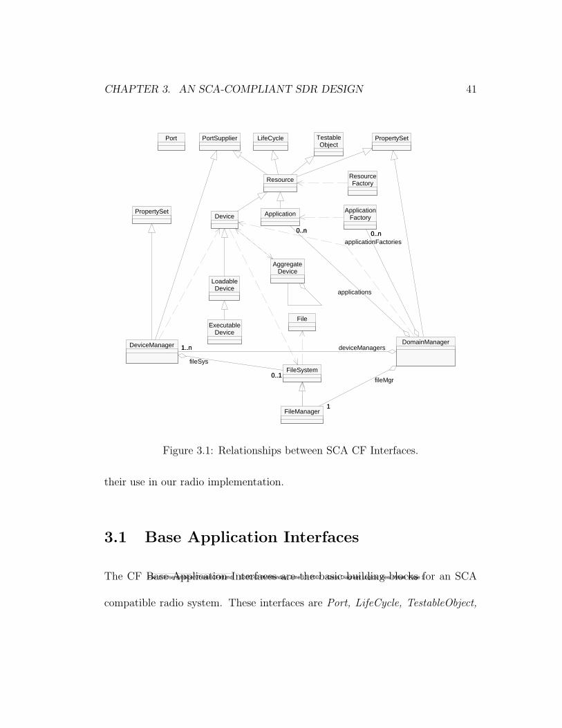
CF DeviceManager. Figure 3.1 shows the relationships between CF interfaces
in UML [40].
The following sections describe the SCA CF components in detail and discuss
CHAPTER 3. AN SCA-COMPLIANT SDR DESIGN 41
Port PortSupplier LifeCycle TestableObject
PropertySet
Device
Resource ResourceFactory
LoadableDevice
File
PropertySet
ExecutableDevice
AggregateDevice
FileSystem
FileManager
DeviceManager
0..10..1
fileSys
ApplicationFactoryApplication
DomainManager
11
fileMgr
1..n1..n deviceManagers
0..n0..napplicationFactories
0..n0..n
applications
File: C:\Users\mbicer\Thesis\CFInt.mdl 12:00:42 PM Monday, June 10, 2002 Class Diagram: Logical View / Main Page 1
Figure 3.1: Relationships between SCA CF Interfaces.
their use in our radio implementation.
3.1 Base Application Interfaces
The CF Base Application Interfaces are the basic building blocks for an SCA
compatible radio system. These interfaces are Port, LifeCycle, TestableObject,
CHAPTER 3. AN SCA-COMPLIANT SDR DESIGN 42
PropertySet, PortSupplier, Resource and ResourceFactory. These interfaces are
used by the application layer and the Framework Control Interfaces to assemble
an application. They are implemented by the application developers.
The components of an SCA compatible application connect to each other
through ports. The Port interface provides the connect and disconnect oper-
ations needed to assemble and disassemble components. Application specific
ports inherit the Port interface. These component dependent, application spe-
cific ports define the direction and control of the data flow and fan-in fan-out
specifications by implementing additional operations. Components that provide
ports inherit the PortSupplier interface which defines the getPort operation.
This operation is used to obtain a specific consumer or producer port.
The components that need to be initialized or released after instantiation
inherit the LifeCycle interface. This interface provides a generic method to set
a component to a known initial state, and to tear it down. The TestableObject
interface defines a Built-In-Test behavior for components that inherit it. The
runTest method defined by this interface, provides a black box test with test
parameters provided by the user. Components implementing the PropertySet
give access to their properties and attributes. The configure operation of the
PropertySet allows runtime configuration of a component, whereas the query
CHAPTER 3. AN SCA-COMPLIANT SDR DESIGN 43
operation returns its attributes and properties.
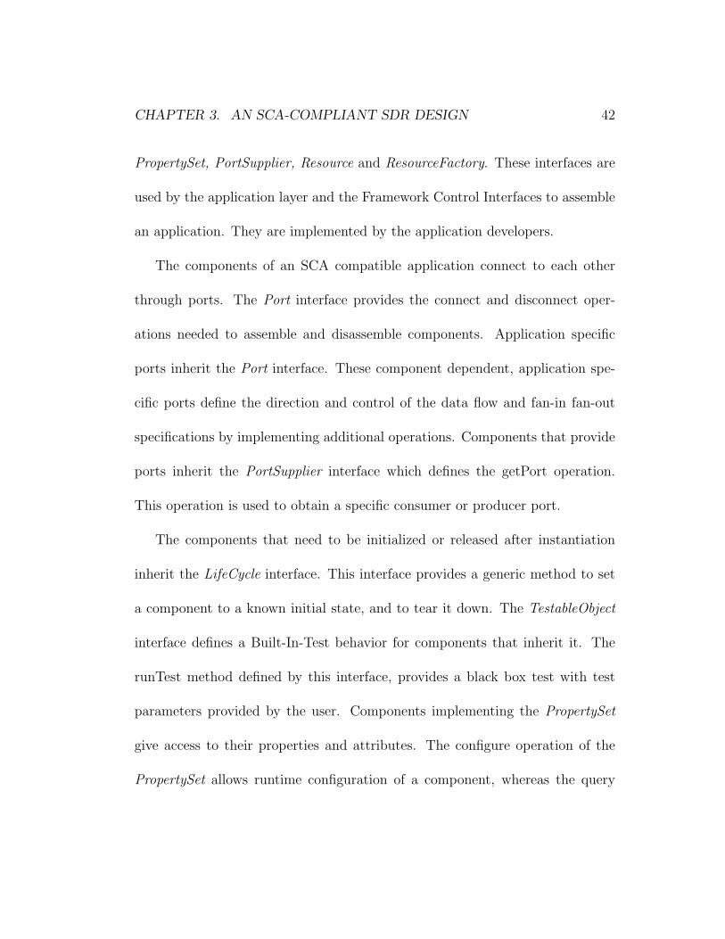
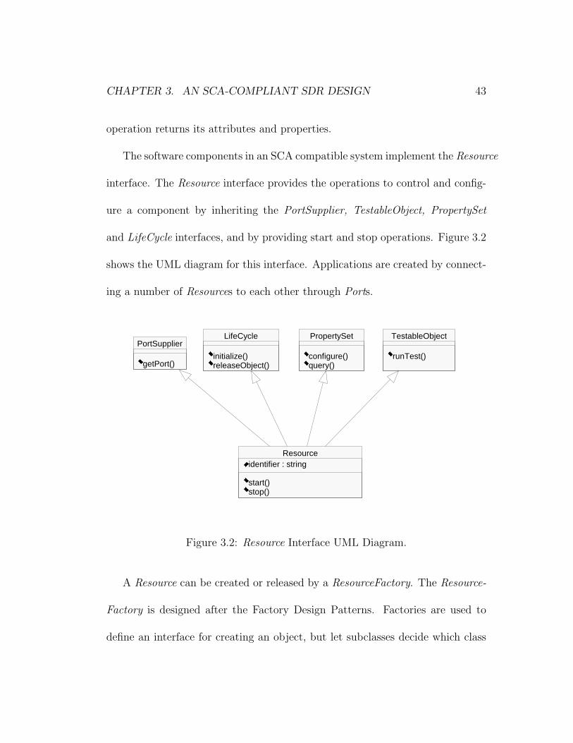
The software components in an SCA compatible system implement the Resource
interface. The Resource interface provides the operations to control and config-
ure a component by inheriting the PortSupplier, TestableObject, PropertySet
and LifeCycle interfaces, and by providing start and stop operations. Figure 3.2
shows the UML diagram for this interface. Applications are created by connect-
ing a number of Resources to each other through Ports.
PortSupplier
getPort()
LifeCycle
initialize()releaseObject()
PropertySet
configure()query()
TestableObject
runTest()
Resourceidentifier : string
start()stop()
File: C:\Users\mbicer\Thesis\resource.mdl 2:16:50 PM Wednesday, May 29, 2002 Class Diagram: Logical View / Main Page 1
Figure 3.2: Resource Interface UML Diagram.
A Resource can be created or released by a ResourceFactory. The Resource-
Factory is designed after the Factory Design Patterns. Factories are used to
define an interface for creating an object, but let subclasses decide which class
CHAPTER 3. AN SCA-COMPLIANT SDR DESIGN 44
to instantiate. Factory Method lets a class defer instantiation to subclasses
[41]. Different kinds of functionality can be implemented by different compo-
nents that inherit the Resource interface. When an Application tries to assemble
these components to build up the system, it may not predict the subclass of
Resource to instantiate. In other words, although an Application knows when
a new resource should be created, it may not know which subclass to create.
The ResourceFactory solves this problem by providing a generic operation to
create Resources. The factory method also provides a client-server isolation in
a CORBA implementation [1]. The factory keeps a list of the object instances
it created, keeping an object reference on the server side, until a release request
is received. This helps the book-keeping of the client and server side reference
counts.
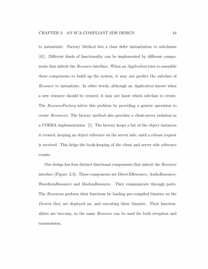
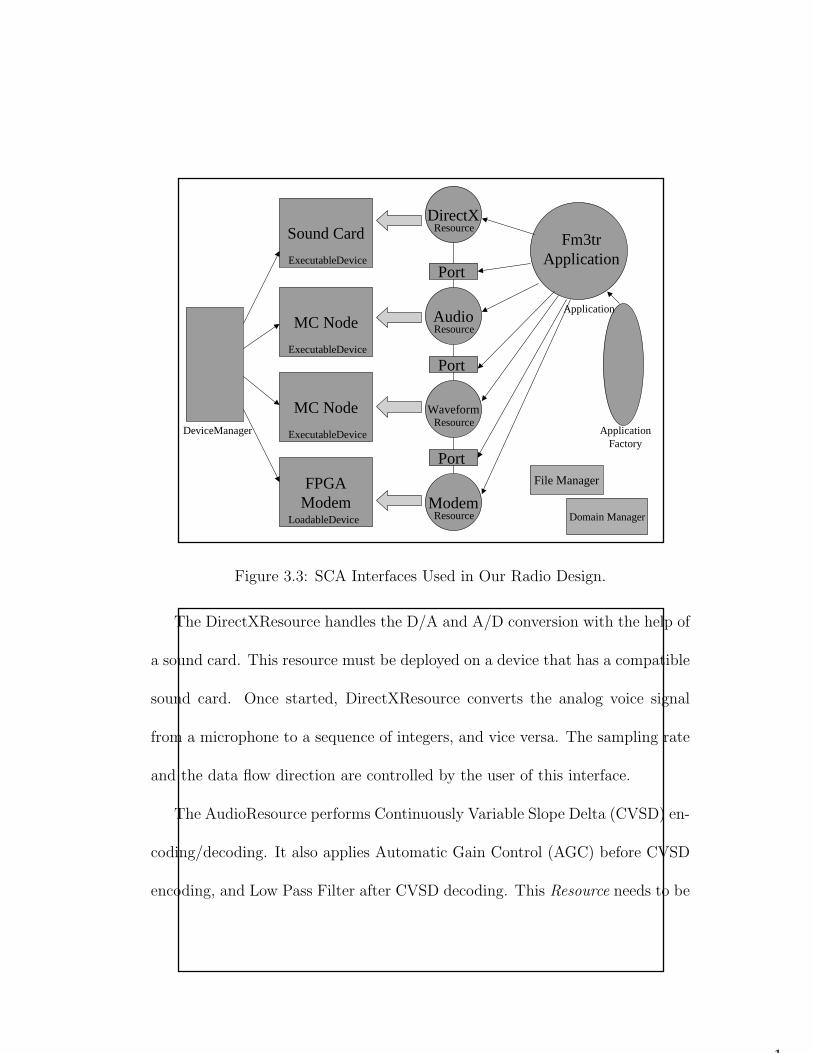
Our design has four distinct functional components that inherit the Resource
interface (Figure 3.3). These components are DirectXResource, AudioResource,
WaveformResource and ModemResource. They communicate through ports.
The Resources perform their functions by loading pre-compiled binaries on the
Devices they are deployed on, and executing these binaries. Their function-
alities are two-way, so the same Resource can be used for both reception and
transmission.
CHAPTER 3. AN SCA-COMPLIANT SDR DESIGN 45
1
Sound Card
MC Node
MC Node
FPGAModem
DirectXResource
ExecutableDevice
ExecutableDevice
AudioResource
DeviceManager
LoadableDevice
ExecutableDevice ApplicationFactory
WaveformResource
ModemResource
Fm3trApplication
Application
Port
Port
Port
Domain Manager
File Manager
Figure 3.3: SCA Interfaces Used in Our Radio Design.
The DirectXResource handles the D/A and A/D conversion with the help of
a sound card. This resource must be deployed on a device that has a compatible
sound card. Once started, DirectXResource converts the analog voice signal
from a microphone to a sequence of integers, and vice versa. The sampling rate
and the data flow direction are controlled by the user of this interface.
The AudioResource performs Continuously Variable Slope Delta (CVSD) en-
coding/decoding. It also applies Automatic Gain Control (AGC) before CVSD
encoding, and Low Pass Filter after CVSD decoding. This Resource needs to be
CHAPTER 3. AN SCA-COMPLIANT SDR DESIGN 46
deployed on an ExecutableDevice.
The WaveformResource creates an FM3TR Waveform packet from a given
data and extracts data from an FM3TR Waveform packet. This Resource needs
to be deployed on an ExecutableDevice with enough processing power.
The ModemResource implements the IF and RF processing of the radio. The
IF and RF processing is designed to be implemented on an FPGA board, so this
Resource loads an FPGA code on an FPGA device. This Resource needs to be
deployed on a LoadableDevice.
The functionality of these Resources are discussed in detail in section 3.4.
3.2 Framework Control Interfaces
The CF Framework Control Interfaces provide the interfaces to assembly and
control the radio system. These interfaces are Application, ApplicationFactory,
DomainManager, Device, LoadableDevice, ExecutableDevice, AggregateDevice
and DeviceManager. The Framework Control Interfaces can be grouped as Do-
main Management Interfaces and Device Management Interfaces. Domain Man-
agement Interfaces consist of DomainManager, Application and ApplicationFactory.
These interfaces provide the services to control, register and unregister appli-
cations and devices. These interfaces are coupled together and they must be
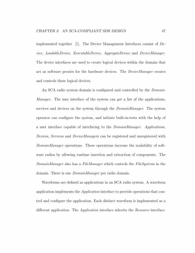
CHAPTER 3. AN SCA-COMPLIANT SDR DESIGN 47
implemented together [1]. The Device Management Interfaces consist of De-
vice, LoadableDevice, ExecutableDevice, AggregateDevice and DeviceManager.
The device interfaces are used to create logical devices within the domain that
act as software proxies for the hardware devices. The DeviceManager creates
and controls these logical devices.
An SCA radio system domain is configured and controlled by the Domain-
Manager. The user interface of the system can get a list of the applications,
services and devices on the system through the DomainManager. The system
operator can configure the system, and initiate built-in-tests with the help of
a user interface capable of interfacing to the DomainManager. Applications,
Devices, Services and DeviceManagers can be registered and unregistered with
DomainManager operations. These operations increase the scalability of soft-
ware radios by allowing runtime insertion and extraction of components. The
DomainManager also has a FileManager which controls the FileSystems in the
domain. There is one DomainManager per radio domain.
Waveforms are defined as applications in an SCA radio system. A waveform
application implements the Application interface to provide operations that con-
trol and configure the application. Each distinct waveform is implemented as a
different application. The Application interface inherits the Resource interface.
CHAPTER 3. AN SCA-COMPLIANT SDR DESIGN 48
An application instance may contain a number of Resource components. The
Application creates these Resources either directly or through a ResourceFac-
tory and assembles them according to the SAD file. On termination (i.e. when
the releaseObject method is called), the execution of the Application is termi-
nated, the allocated resources and devices are deallocated and returned to the
system, and the connectivity between the application’s associated components
is terminated. If a Resource used by an Application is created through a Re-
sourceFactory, the same factory is used to release the Resource. An Application
instance is returned by the create operation of an ApplicationFactory. Each
application type has its own factory. The Software Profile determines the type
of Application created by the ApplicationFactory. As an Application consists of
one or more Resources and Devices, the ApplicationFactory locates these com-
ponents before creating the Application. It initializes, establishes connections
for, and configures the Resources. It also locates the Devices that meet the cri-
teria, and allocates component capacity requirements on these Devices. There
is a Software Package Descriptor for each component in the SAD. The create
operation then loads the components on the chosen Devices.
The hardware devices are represented as logical Devices on SCA systems.
They are functional abstractions for a set of hardware devices [1]. The Device

CHAPTER 3. AN SCA-COMPLIANT SDR DESIGN 49
interface inherits the Resource interface and provides additional operations to
allocate and deallocate capacity. The Device interface stores state information
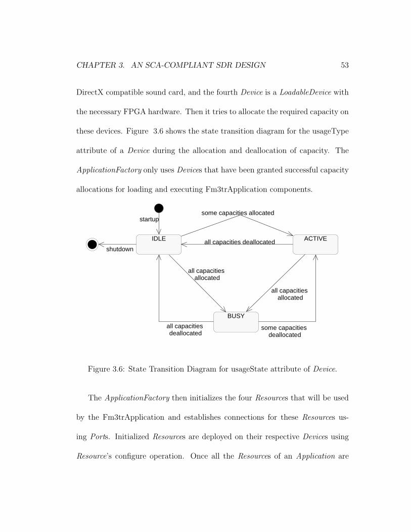
in its usageState, adminState and operationalState attributes. The usageState
attribute is set to IDLE when the Device is not in use, to ACTIVE when it
is in use but it has remaining capacity, and to BUSY when it is in use with
no remaining capacity. The adminState attribute indicates the permission to
use or prohibit against using the Device. It can be LOCKED, UNLOCKED or
SHUTTING DOWN. The operationalState attribute is set to ENABLED if the
Device is functioning, and to DISABLED otherwise. LoadableDevice inherits
the Device interface and adds software loading and unloading behavior. Exe-
cutableDevice extends the interface further by inheriting the LoadableDevice and
adding execute and terminate behavior. The AggregateDevice interface provides
aggregate behavior by holding a list of Devices in its devices attribute, and
defining addDevice and removeDevice operations.
The DeviceManager controls the Devices and services in the domain. There
can be any number of DeviceManagers registered to the DomainManager each
of which controls a different subset of Devices and services. The DeviceManager
keeps lists of the Devices and services it controls, and elements can be added
to or deleted from these lists by using register and unregister operations. A
CHAPTER 3. AN SCA-COMPLIANT SDR DESIGN 50
DeviceManager is not a factory, so it cannot be used to instantiate a Device.
Our radio system has a DomainManager, an Application that creates the
Fm3tr waveform and an ApplicationFactory that creates this Application, three
ExecutableDevices and one LoadableDevice, and a DeviceManager to manage
these Devices. The relationship between these components can be seen in Figure
3.3.
The DomainManager is responsible for the control of our radio system. On
startup, the DomainManager is created and registers itself with the CORBA
Naming Service. Then it reads the DMD file to get the configuration information
of the domain. If a log service is available, it sets the service up. The log service
is not a required component of a JTRS system and thus is not a part of our
design. The DomainManager then creates its FileManager.
After the initialization of the DomainManager, the DeviceManager is created.
The DeviceManager uses the DCD to discover the services to be deployed and
Devices to be created for this DeviceManager. Our current design does not use
any services, so the DeviceManager creates the four Devices that will be used
by the Fm3tr Application. Upon startup, these Devices register themselves with
the DeviceManager. The DeviceManager then initializes and configures these
Devices. There is no particular order for the creation of the Devices, as there is

CHAPTER 3. AN SCA-COMPLIANT SDR DESIGN 51
no aggregation relation between them. Then, it creates a FileSystem and mounts
it to the DomainManager’s FileManager. Finally, the DeviceManager registers
itself with the DomainManager. Figure 3.4 shows the sequence diagram for this
scenario. Boot Up : DeviceManager : XML Parser : Device : DomainManager
Boot Up : DeviceManager : XML Parser : Device : DomainManager
create
Parse DCD
launch Device
registerDevice(in Device)
initialize()
configure(in Properties)
registerDeviceManager(in DeviceManager)
launch, registerDevice, initialize and configure are performed for each Device in the system.
create FileSystem
File: C:\Users\mbicer\Thesis\devicemanager.mdl 1:34:24 PM Wednesday, May 29, 2002 Sequence Diagram: Logical View / DeviceManager Page 1
Figure 3.4: Sequence Diagram for DeviceManager Startup.
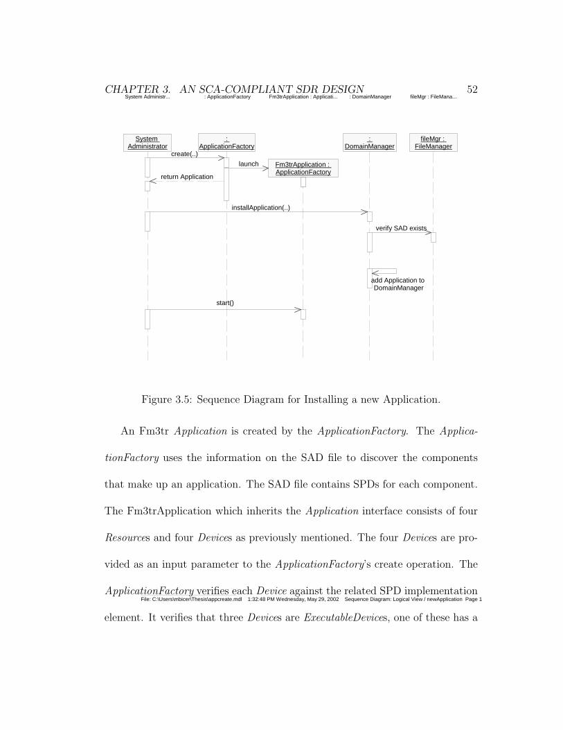
An administrative user can install a new application to the domain by first
requesting a new Application from the ApplicationFactory, and then registering
this Application with the DomainManager (Figure 3.5).
CHAPTER 3. AN SCA-COMPLIANT SDR DESIGN 52System Administr... : ApplicationFactory Fm3trApplication : Applicati... : DomainManager fileMgr : FileMana...
System Administrator
: ApplicationFactory
Fm3trApplication : ApplicationFactory
: DomainManager
fileMgr : FileManager
create(..)
launch
return Application
installApplication(..)
verify SAD exists
add Application to DomainManager
start()
File: C:\Users\mbicer\Thesis\appcreate.mdl 1:32:48 PM Wednesday, May 29, 2002 Sequence Diagram: Logical View / newApplication Page 1
Figure 3.5: Sequence Diagram for Installing a new Application.
An Fm3tr Application is created by the ApplicationFactory. The Applica-
tionFactory uses the information on the SAD file to discover the components
that make up an application. The SAD file contains SPDs for each component.
The Fm3trApplication which inherits the Application interface consists of four
Resources and four Devices as previously mentioned. The four Devices are pro-
vided as an input parameter to the ApplicationFactory’s create operation. The
ApplicationFactory verifies each Device against the related SPD implementation
element. It verifies that three Devices are ExecutableDevices, one of these has a
CHAPTER 3. AN SCA-COMPLIANT SDR DESIGN 53
DirectX compatible sound card, and the fourth Device is a LoadableDevice with
the necessary FPGA hardware. Then it tries to allocate the required capacity on
these devices. Figure 3.6 shows the state transition diagram for the usageType
attribute of a Device during the allocation and deallocation of capacity. The
ApplicationFactory only uses Devices that have been granted successful capacity
allocations for loading and executing Fm3trApplication components.
IDLE
startup
ACTIVEall capacities deallocated
some capacities allocated
BUSY
all capacities allocated
all capacities deallocated
some capacities deallocated
all capacities allocated
shutdown
File: C:\Users\mbicer\Thesis\allcap.mdl 12:26:17 PM Wednesday, May 29, 2002 Activity Diagram: Logical View / allocateCapacity Page 1
Figure 3.6: State Transition Diagram for usageState attribute of Device.
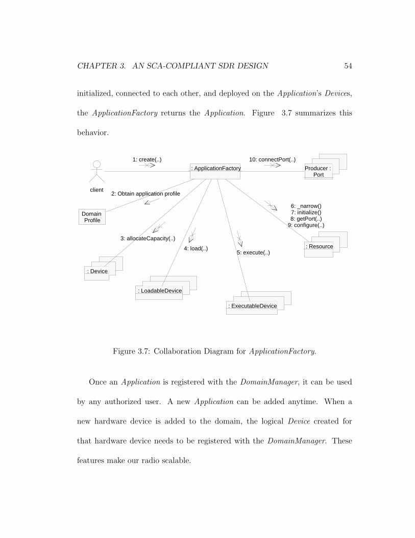
The ApplicationFactory then initializes the four Resources that will be used
by the Fm3trApplication and establishes connections for these Resources us-
ing Ports. Initialized Resources are deployed on their respective Devices using
Resource’s configure operation. Once all the Resources of an Application are
CHAPTER 3. AN SCA-COMPLIANT SDR DESIGN 54
initialized, connected to each other, and deployed on the Application’s Devices,
the ApplicationFactory returns the Application. Figure 3.7 summarizes this
behavior.
: ApplicationFactory
: Device
: LoadableDevice
: ExecutableDevice
: Resource
Producer : Port
Domain Profile
client
3: allocateCapacity(..)
4: load(..)5: execute(..)
6: _narrow()7: initialize()8: getPort(..)
9: configure(..)
10: connectPort(..)
2: Obtain application profile
1: create(..)
File: C:\Users\mbicer\Thesis\appfac.mdl 1:33:33 PM Wednesday, May 29, 2002 Collaboration Diagram: Use Case View / Collab Page 1
Figure 3.7: Collaboration Diagram for ApplicationFactory.
Once an Application is registered with the DomainManager, it can be used
by any authorized user. A new Application can be added anytime. When a
new hardware device is added to the domain, the logical Device created for
that hardware device needs to be registered with the DomainManager. These
features make our radio scalable.

CHAPTER 3. AN SCA-COMPLIANT SDR DESIGN 55
3.3 Framework Services Interfaces
The Framework Services Interfaces provide the system services. These interfaces
are File, FileSystem, FileManager and Timer. These interfaces support both
core and non-core applications.
The File interface provides the operations to read and write files in an SCA
compliant radio domain. The SCA specification defines a file conceptually as a
sequence of octets with a file pointer describing where the next read or write will
occur [1]. Remote access to physical file systems are provided by the FileSystem
interface. The FileSystem also acts as an object factory for Files by defining cre-
ate and open operations. The FileSystem interface makes the underlying pysical
file system transparent to the user. Different file systems like FAT32, NTFS,
and Unix File System can be used with the same interface. When combined
with the location transparency feature of CORBA, the user does not even know
where the physical file actually resides in the system. The FileManager provides
yet another level of abstraction so that multiple, distributed FileSystems may be
accessed through a FileManager. The FileManager inherits the FileSystem inter-
face and extends it by providing mount and unmount behavior. If no additional
FileSystems are mounted, the FileManager can be treated as a FileSystem.
The behavior for the Timer interface is not defined in the SCA specification

CHAPTER 3. AN SCA-COMPLIANT SDR DESIGN 56
as of version 2.2. Therefore, it is not included in our design.
Our design uses one FileManager created by the DomainManager, and one
FileSystem created by the DeviceManager. The FileSystem is mounted to the
FileManager by the DeviceManager. If additional FileSystems are added to the
system and mounted to the FileManager, the user can transfer Files between
them as if they are different directories. The different physical file systems are
transparent to the user. All the file accesses in our radio are provided by the
FileSystem. A file resident on the physical file system is not existent in the SCA
domain unless it is opened or created by the FileSystem.
3.4 The FM3TR Waveform
The Fm3tr waveform application is built as a standalone application. The pre-
compiled binaries that build up this application are loaded on the SCA domain
by Resources. The application consists of 4 parts:
• Sound Record and Playback
• Audio Processing
• Waveform Processing
• Modem
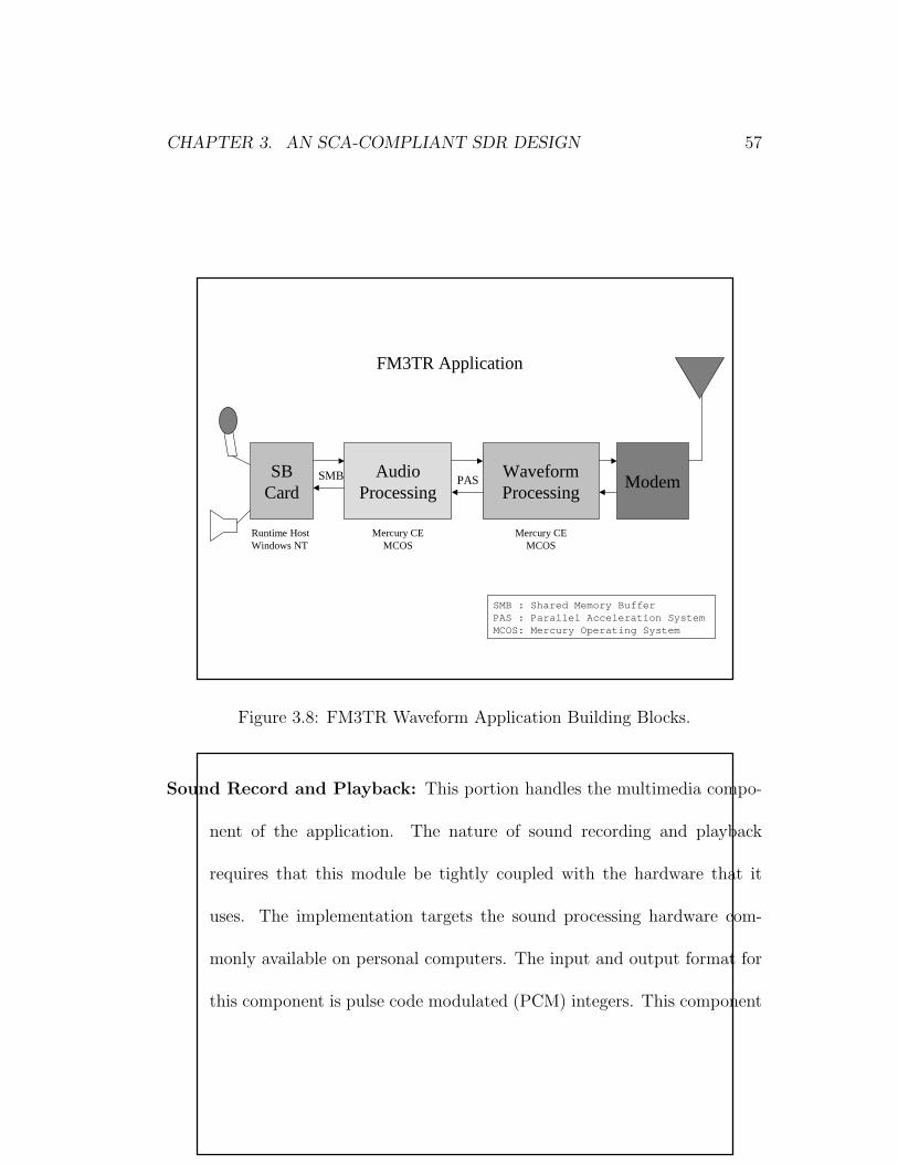
CHAPTER 3. AN SCA-COMPLIANT SDR DESIGN 57
Figure 3.8 shows the top level building blocks for this application on one of
the target platforms.
1
AudioProcessing
WaveformProcessing
SBCard
Runtime HostWindows NT
Mercury CEMCOS
Mercury CEMCOS
SMB PAS
FM3TR Application
Modem
SMB : Shar ed Memor y Buf f erPAS : Par al l el Accel er at i on Syst emMCOS: Mer cur y Oper at i ng Syst em
Figure 3.8: FM3TR Waveform Application Building Blocks.
Sound Record and Playback: This portion handles the multimedia compo-
nent of the application. The nature of sound recording and playback
requires that this module be tightly coupled with the hardware that it
uses. The implementation targets the sound processing hardware com-
monly available on personal computers. The input and output format for
this component is pulse code modulated (PCM) integers. This component
CHAPTER 3. AN SCA-COMPLIANT SDR DESIGN 58
is loaded on the SCA system by DirectXResource.
Audio Processing: The audio subsystem takes input from the sound record
and playback subsystem in the form of PCM integer data. These numbers
are encoded using the CVSD modulation algorithm, and a binary output is
created. On the other side, the audio subsystem receives the data from the
waveform processing subsystem. The data is CVSD-decoded and the result
is fed into the sound record and playback subsystem. This component is
loaded on the SCA system by AudioResource.
Waveform Processing: - This component is the part that actually generates
the waveform used by the radio. Our radio implementation currently uses
the FM3TR waveform. The waveform used by a radio can be changed by
replacing this component. This plug-n-play behavior provides interoper-
ability.
The waveform subsystem takes input from the audio processing subsystem
in the form of CVSD modulated data. A preamble is attached to the
message. The preamble specifies the start of the hopping frequency for
the message. The frame contains four data hops and a sync hop. If the
message is the last of the frame then an end-of-message (EOM) pattern is
also sent with the data. The output is sent to a modem, which converts
CHAPTER 3. AN SCA-COMPLIANT SDR DESIGN 59
it to a format suitable for RF transmission.
On the other side, the waveform subsystem receives the data from the
modem. A correlation function is applied to this input data to determine
the hop rate being used. The preamble is always sent at the beginning
frequency of the hopping band selected. The data received from the mo-
dem is demodulated. Correlation is then applied to the demodulated data.
If the correlation is successful then the data is extracted from the frame.
This is CVSD modulated data and needs further processing by the audio
subsystem.
This component is loaded on the SCA system by WaveformResource.
Modem: The word modem can have different meanings for software engineers
and radio engineers. In this design, it represents all the functionality in
Intermediate Frequency (IF) and RF processing blocks of a radio system.
This component receives data from the waveform subsystem, upconverts
it to an IF and then an RF stage and passes the signal to the antenna.
On receive, it downconverts the received signal from the antenna to an IF
stage, and then to baseband. The baseband signal is sent to the wave-
form processing subsystem. This component is designed to be an FPGA
implementation, and it is loaded to the SCA system by ModemResource.
Chapter 4
Implementation
We provide a reference implementation for the SCA to explore the advantages
and difficulties of this architecture. Problems that do not emerge during the
design phase can often be identified during the implementation. We implemented
this radio application as a proof-of-concept for the SCA. The lessons learned
throughout the implementation are also presented.
The implementation is documented using Rational Software’s Rose program.
The CORBA middleware is included using OIS’s ORBexpress. The development
and debugging is performed on a Pentium Windows NT machine, using Microsoft
Visual Studio. The target platforms used to test the application are two Pentium
machines running Windows NT, a Sun Blade machine running Solaris, and a
60
CHAPTER 4. IMPLEMENTATION 61
two-node Mercury machine running MCOS.
We implemented our project in C++ using OIS ORBexpress as our ORB.
C++ is chosen as the implementation language to be compatible with legacy
code and to get faster executables. A java implementation is considered as future
work and is discussed in chapter 6. ORBexpress is chosen as the ORB because
we have the same ORB available for all three platforms we were targeting, and
the ORB can be used with our C++ development environment. The runtime
performance of ORBexpress also exceeded our expectations.
Systems that employ CORBA as a middleware consist of clients and servers.
In our project, the user interfaces are implemented as clients that use the CF and
FM3TR components residing on one or more servers. CORBA does not specify
how the clients connect to the servers (i.e. a bind method), and ORBexpress
uses a bind operation to connect to OIS ORBs, and a foreign bind operation to
connect to other vendors’ ORBs. This portability problem can easily be solved
by recompiling the client main code with the new ORB that is to be used. The
server holding the FileSystem objects should run on the machine having the
physical files system that will be used by the FileSystem. The servers that the
Devices reside on should be running on the respective physical devices. Other
servers can run on any machine with sufficent processing power. If one machine
CHAPTER 4. IMPLEMENTATION 62
can meet all the constraints, then the whole system can be run with one server.
The client server models used in our project are discussed in detail in chapter
5.
Our radio system uses two IDL files: cf.idl and fm3tr.idl. cf.idl is the origi-
nal IDL file published by the JTRS. It contains the definitions for the SCA CF
Interfaces. fm3tr.idl is the project-specific IDL file. It includes cf.idl, and de-
fines the project-specific interfaces like Fm3trApplication and DirectXResource.
These interfaces inherit the related CF interfaces (i.e. Fm3trApplication inherits
Application, MCNodeDevice inherits ExecutableDevice). Any SCA compatible
radio implementation that will use our core framework can include our cf.idl
and derive their components from our CF components.
The interfaces in cf.idl are put in the CF module. Seperating the interfaces
using different namespaces avoids unintentional naming collisions. The inter-
faces in fm3tr.idl are in the FM3TR module. Defining a prefix in the IDL file is
another method used in our project to avoid conflicts. The prefix defined in the
file is added to the objects’ names in the orb’s name repository so that different
CORBA objects having the same names but using different CF implementations
do not conflict.
CHAPTER 4. IMPLEMENTATION 63
The Resource inherits the PortSupplier, TestableObject, LifeCycle and Prop-
ertySet and overrides their operations. A Resource is deployed on a Device by
using the configure operation of the PropertySet interface. The configure oper-
ation has a Properties parameter, which is an unbounded sequence of type any.
A pointer to the Device that the Resource will be deployed on is put in this
sequence, before the configure operation is called. The Resource’s start and stop
methods use this Device to perform their operations. The getport operation
inherited from the PortSupplier returns a port, that can be used to connect the
Resource to other Resources. The getPort operation’s return type is Object. The
ports that will be used to connect Resources are not defined by the SCA. The
Port interface defined by the SCA is meant to be used as a PortUser interface,
that will connect and disconnect ports. For this reason, the getPort operation
does not return objects of type Port but of type Object.
DirectXResource, AudioResource, WaveformResource and ModemResource
inherit the Resource interface. The DirectXResource, AudioResource and Wave-
formResource expect to be deployed on ExecutableDevices. As ExecutableDevice
inherits LoadableDevice, they load the precompiled binaries they will use for
execution on their respective Devices and execute them. The DirectXResource
CHAPTER 4. IMPLEMENTATION 64
also checks for soundcard compatibility. The ModemResource is an FPGA im-
plementation, and is not implemented as a part of this project.
ApplicationFactory is implemented using the Factory Design Pattern. An
Application should only be created through an ApplicationFactory. The Ap-
plicationFactory creates a linked list to keep references to the Applications it
created. The constructor makes a copy of its Portable Object Adapter (POA)
and uses its own POA to create the Applications. Another alternative would be
using a configuration operation to assign a new POA to the Applications to be
generated. Since it is required by the SCA to have a specific ApplicationFactory
for every Application type, we believe it is reasonable and more efficient to use
the same POA. If different policies need to be employed by the ApplicationFac-
tory’s POA and the Application’s POA, then a new ApplicationFactory interface
that inherits the original ApplicationFactory can be defined. The constructor
also initializes the list of the Applications by setting the head element to null.
The copy constructor behavior is not well defined for object factories. Our
copy constructor creates a new factory, but does not create the objects created
by the copied factory. It only copies the references in the list. The use of
copy constructors for object factories is discouraged. The destructor releases
the Applications and the Resources used by those Applications, and deletes the
CHAPTER 4. IMPLEMENTATION 65
list.
The create operation checks its input parameter of type Properties, to learn
the Devices that will be used by the Application. These Devices should also
match the Devices defined in the SAD and SPD files for this Application. Our
current implementation does not parse an XML file, but uses hard-coded infor-
mation. It verifies that three Devices are ExecutableDevices, one of these has
a DirectX compatible sound card, and that the fourth Device is a LoadableDe-
vice with the necessary FPGA hardware. The FPGA part of the project is not
implemented, so the last check is a dummy check. Then it tries to allocate the
required capacity on these devices.
If the allocations succeed, the ApplicationFactory initializes the DirectXRe-
source, AudioResource and Waveform Resource that will be used by the Fm3trApplication
and establishes connections for these Resources using Ports. Initialized Resources
are deployed on their respective Devices using Resource’s configure operation.
Once all the Resources of an Application are initialized, connected to each other,
and deployed on the Application’s Devices, the create operation returns the Ap-
plication.
The Application does not have specific behavior other than the get and set
operations for its attributes. Application specific behavior is implemented by

CHAPTER 4. IMPLEMENTATION 66
classes that inherit the Application. In our project, Fm3trApplication imple-
ments the behavior. Its start operation starts the DirectXResource, AudioRe-
source and WaveformResource in the given order. The Application does not
interact with Devices, as the Resources are already deployed on their Devices by
the ApplicationFactory. The stop operation stops the Resources.
The Device interface provides a software proxy for a hardware device. The
Device objects are the only objects in the system that have access to the phys-
ical hardware. A Device holds information about its administrative, usage and
operational states. The administrative state is set to UNLOCKED, the oper-
ational state is set to ENABLED, and the usage state is set to IDLE in the
constructor. The usage state is changed by allocateMemory and deallocate-
Memory operations. The capacity requirements vary among devices, and a new
device interface that inherits CF Device can override these operations accord-
ing to its unique requirements. Figure 3.6 summarizes this behavior. The
releaseObject method releases the AggregateDevices of the Device. Then, it sets
the adminState attribute to SHUTTING DOWN and releases the Device from
the CORBA environment.
The LoadableDevice inherits the Device. It extends the Device by imple-
menting additional load and unload behavior. The ExecutableDevice extends

CHAPTER 4. IMPLEMENTATION 67
the Device further by inheriting LoadableDevice and adding execute and termi-
nate behavior. The load operation provides the mechanism for loading software
on a specific device. The loaded software may be subsequently executed on the
Device, if the Device is an ExecutableDevice. The load operation uses the its
FileSystem to get access to physical file. The execute operation returns the pro-
cess ID (pid) of the process it just started. This pid is specific to the operating
system of the physical device (or the operating system of the runtime host, when
the hardware devices are controlled by a runtime host, and the logical Device
interacts with this host). Our implementation has two kinds of ExecutableDe-
vices. The SoundCardDevice runs on a Windows NT machine with a sound card
that supports DirectX. The MCNodeDevice also runs on a machine that is used
as a runtime host for Mercury nodes. Both of these Devices use Windows API’s
CreateProcess method to run the processes and obtain the pid. The terminate
method issues a kill system call with the provided pid. The FPGAModem De-
vice is a LoadableDevice but is not implemented as a part of this project. Figure
4.1 shows how the client and server sides of our project map to the hardware.
The DeviceManager does not need to run on the same platform as the Devices
it managed. The CORBA middleware provides location transparency for these
two interfaces. The DeviceManager keeps a list of the Devices that are registered
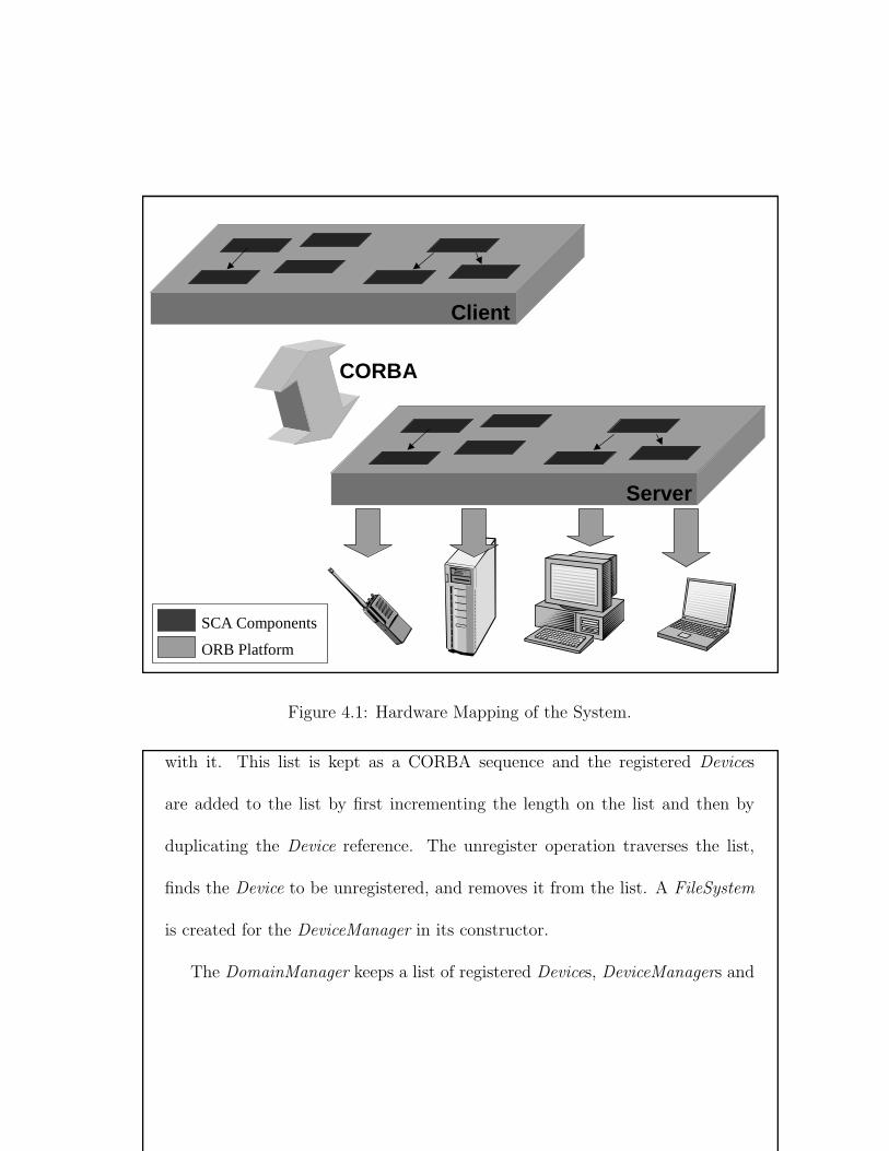
CHAPTER 4. IMPLEMENTATION 68
1
Client
Server
CORBA
SCA Components
ORB Platform
Figure 4.1: Hardware Mapping of the System.
with it. This list is kept as a CORBA sequence and the registered Devices
are added to the list by first incrementing the length on the list and then by
duplicating the Device reference. The unregister operation traverses the list,
finds the Device to be unregistered, and removes it from the list. A FileSystem
is created for the DeviceManager in its constructor.
The DomainManager keeps a list of registered Devices, DeviceManagers and
CHAPTER 4. IMPLEMENTATION 69
Applications. The register and unregister operations are implemented the same
way they are implemented in the DeviceManager. The DomainManager is used
by the user interface to control the system.
The file services are implemented using low level C file I/O interfaces. This
provides us code portability between different platforms. The File object holds
the file handle in a private attribute with no get and set methods. This at-
tribute’s value is assigned in the constructor and cannot be changed until the
File is destroyed. The FileSystem keeps a list of created physical files. Every
FileSystem holds its files in its own directory. The constructor of the FileSys-
tem reads the files in this directory, opens them in the physical file system and
generates a File object for each file. These files are kept open until they are
removed from the system. That is, when a user calls the close operation on a
File, a flag is set, but the physical file is not closed. The File is virtually closed
to the user. This is done to prevent access to the physical files from outside the
SCA system. The FileSystem holds its files as long as it is alive. This implemen-
tation creates a limitation. The number of files that can be created in our SCA
system is limited to the number of files that can be opened simultaneously in
the underlying operating system. This is not an acceptable limitation in a real
system but a practical security implementation for a proof-of-concept design.
CHAPTER 4. IMPLEMENTATION 70
The read operation reads blocks of data from the physical file into a tempo-
rary buffer, then sets the octet sequence defined in the interface point to this
buffer. The reverse is done for the write operation. This method prevents copy-
ing blocks of data from one buffer to another for every read and write operation.
The copy operation uses a similar approach. The read and write operations
update the filePointer attribute after every successful operation.
The FileSystem behaves like an object factory for Files by providing open
and create operations. The Files generated by the FileSystem are kept in a list.
This list is used and modified by the FileSystem operations. A File that is not
in this list does not exist for the rest of the SCA system. Like other factories,
the FileSystem makes a copy of its POA in the constructor, stores it in a private
attribute, and uses it to create File objects.
Chapter 5
Results
5.1 Client Server Communication Models
We tested our program using a number of client-server combinations. We ex-
amined single client, single server; single client, multiple servers; and multiple
clients, single server configurations. The multiple clients, multiple servers case
does not provide additional information, and thus is not examined.
In the single client, single server case, all the CORBA components run on
one server machine. The client can be any machine running Windows NT.
The server needs to be a Windows NT machine configured as a runtime host
capable of running applications on Mercury nodes. The communication between
71
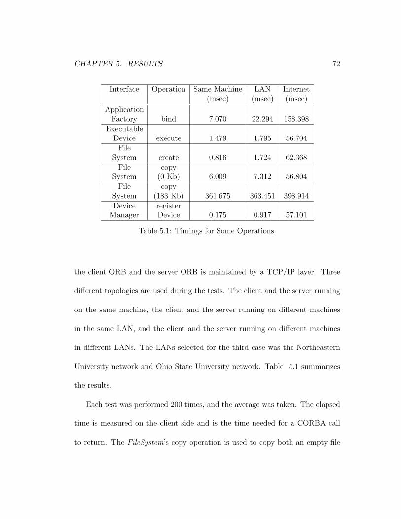
CHAPTER 5. RESULTS 72
Interface Operation Same Machine LAN Internet(msec) (msec) (msec)
ApplicationFactory bind 7.070 22.294 158.398
ExecutableDevice execute 1.479 1.795 56.704File
System create 0.816 1.724 62.368File copy
System (0 Kb) 6.009 7.312 56.804File copy
System (183 Kb) 361.675 363.451 398.914Device register
Manager Device 0.175 0.917 57.101
Table 5.1: Timings for Some Operations.
the client ORB and the server ORB is maintained by a TCP/IP layer. Three
different topologies are used during the tests. The client and the server running
on the same machine, the client and the server running on different machines
in the same LAN, and the client and the server running on different machines
in different LANs. The LANs selected for the third case was the Northeastern
University network and Ohio State University network. Table 5.1 summarizes
the results.
Each test was performed 200 times, and the average was taken. The elapsed
time is measured on the client side and is the time needed for a CORBA call
to return. The FileSystem’s copy operation is used to copy both an empty file
CHAPTER 5. RESULTS 73
and a 183 Kb file, to show the overhead. The data obtained from these tests
is not stable, as the results depend on various other factors like the hard disk
speed and data cache structure of the server machine, quality and bandwidth
of connection between the machines and the way the OS handles systems calls.
The table is rather for illustrative purposes.
As can be seen from Table 5.1, the completion times for the same machine
and the same LAN cases are not much different. As an optimization, the client
ORB does not perform an over-the-network call when it realizes that the server
ORB is on the same machine. Over a 100 Megabit LAN, the overhead for
sending a message back and forth is so low that the two cases provide pretty
much the same results. But when there is a significant distance between the
two computers, overhead can be more than the time it takes to complete the
operation. Still, a low bandwidth waveform such as FM3TR can be deployed
and run on a distributed system like the case for two different LANs. A time
consuming operation such as copying a 200 Kb file takes the same time in all
cases because the operation itself takes more time than the overhead and the
operation is, by its nature, very dependent on other factors like hard disk and
memory.
The one client, multiple server case is tested by running the File, FileSystem
CHAPTER 5. RESULTS 74
and FileManager objects on one server, and the rest of the CORBA components
on another server. The server running the file services can be any machine with
a Windows NT OS and a hard disk. The other server must be a Windows NT
machine configured as a runtime host capable of running applications on Mercury
nodes. The client communicates with the server running the DomainManager,
and the DomainManager and the DeviceManagers communicate with the file
services server. As in other cases, the topology is transparent to the user.
The multiple client, one server configuration is very similar to the one server,
one client case except that multiple clients connect to the same server. Depend-
ing on the number of object instances on the server, clients can either bind to
the same CORBA object, or bind to seperate CORBA objects. For example, if
there is only one DeviceManager instance on the server, all the clients use the
same DeviceManager. In this case, while the DeviceManager is serving a client,
other client requests to the DeviceManager are queued and the clients blocked.
If there are multiple DeviceManagers, clients can use different instances. The
DeviceManagers can be distunguished by their unique names.
We also examined the sizes of the binaries used in the tests. Table 5.2 shows
CHAPTER 5. RESULTS 75
the results. The Sound Processing, Audio Processing and Waveform Process-
ing entries are the binaries loaded and executed by the DirectXResource, Au-
dioResource and WaveformResource, respectively. These are the pre-compiled
FM3TR excutables, and are not discussed as a part of this thesis. In an SCA
implementation, these components are supplied by the waveform developer. It
is important to note that these files must be resident on the device at all times.
In handheld devices, if the executables are to be kept on a flash memory, the
memory should have additional space for these components.
The various client and server entries in the table reflect the executable sizes
when the source code is compiled and linked with the ORBexpress libraries. The
Complete Client entry is the fully-functional client used in our application. The
Dummy Client entry is a client that performs no operations (it has an empty
main function). From the results, we can see that the size difference between a
fully-functional radio client and a client that does not perform any operations is
not much. That is because most of the code in a client is generated to provide
the capability to use the CORBA objects in the system. Even though none of
these objects are used in the dummy client case, the capability is still there.
If the capability to use some of the CORBA objects is not needed, then the
stubs for these objects should not be generated. This is done by not defining

CHAPTER 5. RESULTS 76
Binary Size Executed(bytes) By
SoundProcessing 147,530 DirectXResource
AudioProcessing 225,346 AudioResourceWaveformProcessing 712,618 WaveformResourceComplete
Client 828,017 userDummyClient 766,017 test case
File ServicesClient 512,070 user
Complete administrativeServer 1,479,713 user
DummyServer 1,159,238 test case
File Services administrativeServer 557,126 user
Table 5.2: Binary Sizes of Components.
CHAPTER 5. RESULTS 77
these objects in the client’s IDL file. This approach can decrease the resulting
executable size significantly. The File Services client is created as an example
for this approach. The executable size of this client is much less than the other
clients, but it does not have access to the CORBA objects other than the file
services objects.
The situation is different in servers. The difference between a complete server
and a dummy server is much greater. That is because, in CORBA systems, the
functionality is defined and implemented on the server side. Thus, a dummy
server (a server with objects that do not perform any operations) has much less
code than a functional server. Still, if the server does not provide some CORBA
objects at all (they are not defined for the server), then even the skeletons for
these objects are not needed. This decreases the resulting executable size and
can be seen in the results for the File Services server.
5.2 Code Reusability
One of the goals of this project was providing a CF implementation that can be
used by any SCA-compatible radio system. For this purpose, the project was
implemented in two layers. The inner layer consists of the code generated for
cf.idl. This is the implementation code for the interfaces defined in the SCA. The
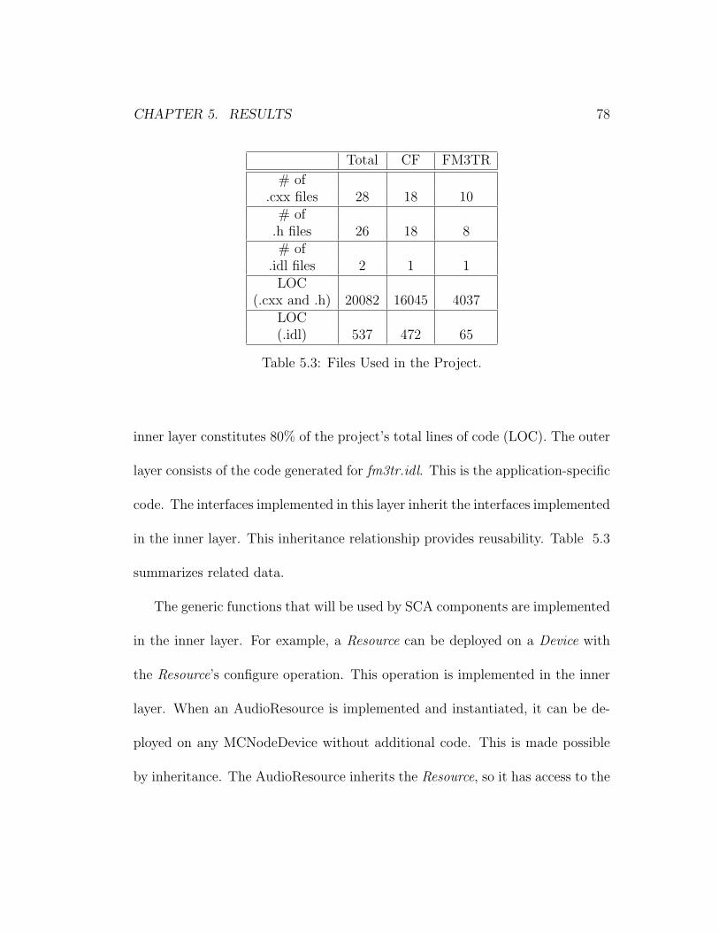
CHAPTER 5. RESULTS 78
Total CF FM3TR
# of.cxx files 28 18 10
# of.h files 26 18 8# of
.idl files 2 1 1LOC
(.cxx and .h) 20082 16045 4037LOC(.idl) 537 472 65
Table 5.3: Files Used in the Project.
inner layer constitutes 80% of the project’s total lines of code (LOC). The outer
layer consists of the code generated for fm3tr.idl. This is the application-specific
code. The interfaces implemented in this layer inherit the interfaces implemented
in the inner layer. This inheritance relationship provides reusability. Table 5.3
summarizes related data.
The generic functions that will be used by SCA components are implemented
in the inner layer. For example, a Resource can be deployed on a Device with
the Resource’s configure operation. This operation is implemented in the inner
layer. When an AudioResource is implemented and instantiated, it can be de-
ployed on any MCNodeDevice without additional code. This is made possible
by inheritance. The AudioResource inherits the Resource, so it has access to the
CHAPTER 5. RESULTS 79
configure operation. The configure operation uses the Device class in its code.
As the MCNodeDevice inherits the Device, it can be used anywhere a Device is
expected.
Our project consists of 20082 LOC. 1604 LOC of this is the CF implemen-
tation. The rest (4037) is specific to the FM3TR implementation. This shows
that 80% of the code used in our project is reusable. (Please note that this 4037
LOC is not the FM3TR application itself. It is the code needed to define and
implement additional components that will run the FM3TR application bina-
ries. The code for these generated binaries is over 30000 LOC and is out of the
scope of this project.)
Since FM3TR is a relatively simple, low bandwidth waveform, not many
additional components are needed to run this application. But even with a more
complex waveform, our implementation promises reusabilityon the order of 50%.
As more and more waveforms are added to the radio system, the ratio of the CF
over the rest of the system decreases. But this time, the components derived
from the CF can be reused by different waveforms. (i.e. An AudioResource can
be used by both an FM3TR and an OFDM application.)
The level of abstraction or generalization can also be increased to have more
reusable code. For example, a ComputeNodeDevice can be derived from the

CHAPTER 5. RESULTS 80
ExecutableDevice with additional behavior for compute nodes. Then an MCN-
odeDevice or a PentiumDevice can inherit the ComputeNodeDevice.
23 classes are used in this implementation. 17 of these classes are used to
build the SCA framework, and the remaining 6 are used to load and execute
an FM3TR application. 10 classes inherit the Resource and redefine or add
to its operations. The Resource is the major building block component in our
design. As the Resource itself inherits the LifeCycle, PropertySet, Portsupplier
and TestableObject, these 10 classes also inherit these interfaces indirectly and
provide the operations defined by them. The PropertySet interface is inherited
by all the classes except the file services.
5.3 The File System
The file services interfaces of the SCA provide a generic API to the user. All the
file operations are performed through these services. Files that are not created
by the CF file services does not exist for the radio domain.
The file services consist of the FileManager, FileSystem, and File interfaces.
These interfaces provide operations to create, read, write, copy, open, close
and remove files. The physical files are represented as File objects in the SCA
domain. The user does not need to know about the details of the physical file

CHAPTER 5. RESULTS 81
system that is being used. In other words, the physical file system is transparent
to the user.
Our project uses the low level C File I/O to implement these interfaces.
This gives us the opportunity to write portable code across various platforms.
A removal of the “ ” sign before the I/O functions make the Windows code
compilable under Unix. (i.e. read() in Windows is read() in Unix.)
We implemented a Windows version and a Unix version of the file services
interfaces, and tested compatibility. The SCA does not make a distinction be-
tween binary files and text files. This gave us the chance to implement the file
operations in binary mode, thus solving another one of the portability issues.
To test compatibility, we created a FileSystem on a Windows NT machine
and another one on a Unix machine. The two FileSystem objects are mounted
to the same FileManager. The Files are then created on one FileSystem and
read on the other, copied from one FileSystem to the other, and so on with
no compatibility problems. A DeviceManager residing on a Windows machine
instantiated its FileSystem on a Unix machine, and performed all of its file
operations with no problems. These tests proved the transparency of our file
services implementation.
CHAPTER 5. RESULTS 82
5.4 Interoperability
Most of the interoperability in our radio system is provided by the CORBA
middleware. With the help of well defined interfaces, the components that build
up the system can be replaced with components written by other developers.
Components running on different platforms interact seamlessly.
The applications consist of plug-and-play parts that are connected to each
other. These parts are defined as Resources, and they are connected through
Ports. The Resource can be thought of as a black box: another Resource with
completely different functional behavior but the same Port behavior can be used
as a replacement. In our project, the WaveformResource can be replaced with
another Resource that generates a different waveform. A Resource’s functionality
can also be changed by redefining the binary file it will execute on a Device.
This feature brings interoperability at a more abstract level. Two different
radios can interoperate by agreeing on a coalition waveform and switching to it.
It could even be possible to upload a WaveformResource component from one
radio to the other to provide interoperability.
Chapter 6
Conclusions and Future Work
Software defined radios enable us to build reconfigurable and interoperable radios
that can be upgraded for future technologies. Defining an open architecture and
implementing radios compatible with this architecture further enhances interop-
erability. For this purpose, JTRS defined the SCA. In this thesis, we developed
an open-source reference implementation of SCA version 2.2 that supports code
reusability.
The CF part of the implementation can be used by any SCA compatible radio
implementation. This parts provides code for generic operations, and shells for
application specific operations. The shells can be overridden through inheritance
by the application specific components.
83
CHAPTER 6. CONCLUSIONS AND FUTURE WORK 84
The design of our project can be used to guide future SCA compliant ra-
dio implementations. Although a specific waveform, FM3TR, is used for the
proof-of-concept stage, the project provides a waveform-independent design.
The component definitions are not specific to FM3TR, and can be used with
other waveforms.
The SWRADIO DSIG of OMG is in the process of defining a PIM for the
SCA. A complete MDA application consists of a definitive PIM, plus one or
more PSMs and complete implementations. Our project can be the missing
part of the SCA MDA effort by defining a PSM that results from the mapping
of the PIM to the platforms we used. The PSM can also influence the ongoing
development of the PIM.
Our project implemented only the mandatory parts of the SCA. Using a fairly
simple waveform application enabled us to develop an implementation with a
minimum number of components. Because of this, our reference implementation
can be used to define a minimum SCA.
The contributions of this thesis can be summarized as follows:
• We developed an open-source reference implementation of the SCA version
2.2.
• We provided a design that can guide the development of SCA compatible
CHAPTER 6. CONCLUSIONS AND FUTURE WORK 85
radio systems.
• We provided reusable SCA CF implementation code.
• We defined a PSM that is a mapping of the OMG PIM for the SCA.
• We proposed a minimum SCA definition.
Future work on SCA compliant software radios can focus on Java based
implementations. The promise of Java is that it is the “universal glue” that
connects users with information, whether that information comes from Web
servers, databases, information providers, and any other imaginable source [42].
This capability satisfies the interoperability needs of software radios. Java’s
built-in security and safety features, and its support for advanced programming
tasks such as network programming, database connectivity, and multithreading
make developing software radios much easier. The Java 2 platform contains a
full implementation of a CORBA 2 compliant ORB. Thus, all applications and
applets that are deployed for the Java 2 platform have the ability to connect to
remote CORBA objects which in turn makes SCA compliance possible. Once
a Java based implementation is developed, ArchJava [17] can be used to test
architecture compliance.
CHAPTER 6. CONCLUSIONS AND FUTURE WORK 86
Use of hardware abstraction layers, radio virtual machines and waveform de-
velopment languages can put the “software” back into the FPGAs and logical
Devices used as work-arounds today. Combining these concepts in a tool to
create a Software Radio Development Environment can facilitate the implemen-
tation of SDRs.
Our project currently does not parse XML files to collect the domain informa-
tion. This information is hard-wired in the components. Future developments
in our radio system should implement an XML Parser and parse the Domain
Profile files, to gather the information. The XML Parser needs to interact with
FileSystem and FileManager interfaces.
Designing and implementing a Scheduler can provide many benefits to the
radio system. The Scheduler can manage and control the available hardware
and software resources of the system. ApplicationFactorys can allocate and
deallocate capacities on Devices through the Scheduler. The Scheduler can also
perform runtime optimizations by dynamically changing Device assignments.
It would also be useful to add a logging service to our radio system. The
logging service can consist of log producers and log consumers, where a producer
is any CORBA capable component that produces log records, and a consumer
is an administrative user. The logging services can either implement the SCA

CHAPTER 6. CONCLUSIONS AND FUTURE WORK 87
Log interface or the Lightweight Logging Services specification being developed
by the OMG SWRADIO DSIG at the time of this writing.
Bibliography
[1] Modular Software-programmable Radio Consortium. Software Communica-
tions Architecture Specification. MSRC-5000SCA, V2.2, November 17,2001.
[2] Modular Software-programmable Radio Consortium. Support and Ratio-
nale Document for the Software Communications Architecture Specification.
MSRC-5000SRD, V1.2, December 21, 2000.
[3] P. A. Eyermann and G. L. Bickle. Technical Overview of the JTRS Software
Communications Architecture. Milcom 2001, October 2001.
[4] J. Smith and M. Bicer. Software Communications Architecture. In Proceed-
ings of the High Performance Embedded Computing (HPEC) Conference,
November 2001.
[5] J. Mitola III. Software Radio Architecture. Wiley-Interscience, 2000.
[6] G. Abowd, R. Allen and D. Garlan. Using Style to Understand Descriptions
of Software Architecture. Proceedings of SIGSOFT’93: Symposium on the
Foundations of Software Engineering, December 1993.
[7] D. Garlan and M. Shaw. An Introduction to Software Architecture. Carnegie
Mellon University Technical Report CMU-CS-94-166, January 1994.
88
BIBLIOGRAPHY 89
[8] L. Bass, P. Clements and R. Kazman. Software Architecture in Practice.
Addison-Wesley, 1997.
[9] P. Clements and L. M. Northrop. Software Architecture: An executive
overview. Software Engineering Institute, Carnegie Mellon University, Tech-
nical Report, 1996.
[10] S. Allamanu. Architecture Paradox. Software Engineering Institute,
Carnegie Mellon University, Technical Report, 1996.
[11] J. Doble. Change Resilience Patterns in Software Architecture and Design.
OOPSLA Workshop on Exploring Large Systems Issues, 1997.
[12] B. Hayes-Roth, et al. A Domain-Specific Software Architecture for Adaptive
Intelligent Systems. IEEE Transactions on Software Engineering, vol 21, no
4, pp. 288-301, April 1995.
[13] H. Topcuoglu, et al. The Software Architecture of a Virtual Distributed
Computing Environment. In proceedings of the High Performance Dis-
tributed Computing Conference, 1997.
[14] C. Ermel, R. Bardohl and J. Padberg. Visual Design of Software Archi-
tecture and Evolution based on Graph Transformation. In proceedings of
Uniform Approaches to Graphical Process Specification Techniques (UNI-
GRA’01), Genova, Italy, April 2001.
[15] Space and Missile Systems Center. Functional Requirements Document for
the Standard Satellite Control Segment of the Satellite Control Network.
Los Angeles, CA, August 1995.
BIBLIOGRAPHY 90
[16] SSCS Reference Architecture web site.
http://sunset.usc.edu/research/reference architecture
[17] J. Aldrich, C. Chambers and D. Notkin. ArchJava: Connecting Software
Architecture to Implementation. Proceedings of International Conference
on Software Engineering, May 2002.
[18] OMG Architecture Board MDA Drafting Team. Model Driven Architecture
- A Technical Perspective. Document number ormsc/2001-07-01, Object
Management Group, July 2001.
[19] OMG CORBA web site.
http://www.omg.org/gettingstarted/corbafaq.htm
[20] CRC SCARI Project web site.
http://www.crc.ca/en/html/scari/home/home
[21] L. Bellissard, S. B. Atallah, F. Boyer and M. Riveill. Distributed Application
Configuration. In proceedings of the 16th IEEE International Conference
on Distributed Computing Systems, pp 579-585, 1996.
[22] U. Dayal, H. Garcia-Molina, M. Hsu, B. Kao and M.-C.Shan. Third Gen-
eration TP Monitors: A Database Challenge. ACM SIGMOD Record,
22(2):393-397 , 1993.
[23] J. N. Gray and A. Reuter. Transaction Processing: Concepts and Tech-
niques. Morgan Kaufman, 1993.
[24] Object Management Group. The Common Object Request Broker: Architec-
ture and Specification. Technical Report Version 2.0, Object Management
Group, July 1995.
BIBLIOGRAPHY 91
[25] M. Henning and S. Vinoski. Advanced CORBA Programming with C++.
Addison-Wesley, 1999.
[26] S. Maffeis and Douglas C. Schmidt. Constructing Reliable Distributed Com-
munication Systems with CORBA. IEEE Communications Magazine, Vol.
14, No. 2, February 1997.
[27] B. Bing and N. Jayant. A Cellphone for all Standards. IEEE Spectrum,
May 2002.
[28] M. W. Oliphant. Radio Interfaces Make the Difference in 3G Cellular Sys-
tems. IEEE Spectrum Magazine, Vol. 37, No. 10, October 2000.
[29] SPEAKeasy web page.
http://www.if.afrl.af.mil/div/IFB/techtrans/datasheets/Speakeasy.html
[30] W. Bonser. SPEAKeasy Military Software Defined Radio. International
Symposium on Advanced Radio Technologies, 1998.
[31] Upmal and Lackey. SPEAKeasy, the military software radio. IEEE Com-
munications Magazine, 1995.
[32] Lee Pucker. Solano Communications IC. Spectrum Signal Processing Inc.
White paper, Burnaby, BC, Canada, 2000.
[33] J. Chapin, V. Lum and S. Muir. Experiences Implementing GSM in RDL.
IEEE Milcom 2001, October 2001.
[34] V. Bose, M. Ismert, M. Welborn and J. Guttag. Virtual Radios.
IEEE/JSAC Special Issue on Software Radios, April 1999.
BIBLIOGRAPHY 92
[35] The GNU Software Defined Radio web page.
http://www.gnu.org/software/gnuradio/gnuradio.html
[36] JTRS Overview web site.
http://www.jtrs.saalt.army.mil/overview
[37] D. Benfey. Waveform Development - Concept to Reality. Software Defined
Radio Forum, Waveform Development Environment Workshop, November
2000.
[38] S. P. Reichhart, B. Youmans and R. Dygert. The Software Radio Devel-
opment System. IEEE Personal COmmuncations, vol 6, no 4, pp. 20-24,
August 1999.
[39] R. Prill and M. Antonesco. Programmable channelized digital radio. IEEE
National Telesystems Conference, May 1992.
[40] M. Fowler and K. Scott. UML Distilled. Addison-Wesley, May 1997.
[41] E. Gamma, R. Helm, R. Johnson and J. Vlissides. Design Patterns.
Addison-Wesley, 1995.
[42] C. S. Horstmann and G. Cornell. Core Java 2. Volume I - Fundamentals.
The Sun Microsystems Press, November 2000.