A Smarter Approach - Extremity Medical
20
A Smarter Approach for Charcot Deformity Stronger Beams X - Clip Purchase Power Maximized Mechanical Function Superconstruct Surgical Technique
Transcript of A Smarter Approach - Extremity Medical

A Smarter Approach for Charcot Deformity
C:100M:60Y:7K:1
PMS:2935
C:0M:25Y:100K:0
PMS:123
C:59M:42Y:45K:10
PMS:444
C:92M:66Y:43K:29
PMS:302
MEDICAL Font: Gotham Light 116%, 100 Kernwith .371 case stroke, 13.4° skew
Tagline Font: Gotham Book, Gothic Medium Italic
Stronger Beams X-Clip Purchase Power Maximized Mechanical Function
Superconstruct Surgical Technique
C: 96M: 70Y: 7K: 1
C: 60M: 40 Y: 40 K: 100
C: 0M: 25 Y: 100 K: 0
PMS:2935
PMS:123
R: 5G: 9B: 159
R: 255G: 194B: 14
R: 0G: 0B: 5
R: 255G: 255B: 255
055a9f f fc20e 000005 f f f f f f
Osteotomy Wedge: Eras Demi 100%, 100 Kern
Axis Beam Font: Eras Demi/Medium 100%, 100 Kern
® Eras Medium Axis BeamCharcot Fixation System
The Axis Beaming System offers implants that range from 4.5 to 8.5mm in diameter. The beams are indicated for reconstruction procedures, nonunions and fusions of bones in the foot and ankle including the metatarsals, cuneiforms, cuboid, navicular, calcaneus and talus. Specifically, the 5.5mm, 6.5mm and 7.5mm sizes are indicated for examples which include: medial and lateral column fusion
Customer Service: 888.499.0079www.extremitymedical.com
Product Descriptionresulting from neuropathic osteoarthopathy (Charcot). This technique guide illustrates axial fixation for a medial column. Each Axis Fusion Beam has a corresponding X-Clip. The X-Clip is designed to provide increased thread purchase, compression, and stability for patients with poor quality bone. The use of an X-Clip with an Axis Fusion Beam is optional and left to the surgeon’s discretion.
Surgical Procedure GuidelinesA gastrocnemius recession or percutaneous tendon–achilles lengthening should be con-sidered in midfoot reconstruction to minimize stress across the midfoot and to correct an equinus contracture if present. Surgical exposure consists of a medial incision centered at the apex of the deformity and one or two dorsal longitudinal incisions placed centrally and laterally as needed to reduce and prepare the middle and lateral columns. Preparation for the arthrodesis must include obtaining appropriate alignment of the foot. In addition to joint preparation, bone resection and soft tissue contracture release is often necessary to restore a plantigrade position to the foot. Guidewires for the beams can be used as provisional fixation of deformity correction. In many Charcot patients, the soft-tissue envelope is contracted because of chronic dislocation. In these cases, adequate bone resection to achieve realignment without excessive soft-tissue tension is advised. Osteotomy of the bony structures at the apex of deformity is incorporated into
arthrodesis preparation. The amount of bone resection is left to the discretion of the surgeon and must be individualized in each case. All joints where arthrodesis is intended should be prepared by removal of articular cartilage and subchondral bone, exposing bleeding cancel-lous bone. For example, in a medial column arthrodesis where arthrodesis of all joints is desired, the talonavicular, naviculocuneiform and first tarsometatarsal joints would be prepared as described. Guidewires used for reduction and guidance of fixation devices can be applied percutaneously antegrade, from the talus and calcaneus, or retrograde from the metatarsophalangeal joints. When entering the metatarsals from the retrograde approach, the Guidewires can be placed into the meta-tarsophalangeal joints percutaneously through the plantar aspect of the foot, or an open approach can be used utilizing a dorsal incision to expose the metatarsal head. The Guidewires should be placed into the medullary canal of the metatarsal without breaching the cortical bone.

C:100M:60Y:7K:1
PMS:2935
C:0M:25Y:100K:0
PMS:123
C:59M:42Y:45K:10
PMS:444
C:92M:66Y:43K:29
PMS:302
MEDICAL Font: Gotham Light 116%, 100 Kernwith .371 case stroke, 13.4° skew
Tagline Font: Gotham Book, Gothic Medium Italic
1
General Instruments
70-160mm lengths for use in the 1st metatarsal (medial column)
Utilize 3.2mm Guidewire and all instruments labeled Large
70-150mm lengths for use in the lesser rays (2-5 metatarsals) in conjunction with a medial column beam
Utilize 2.0mm Guidewire and all instruments labeled Small
4.5mm Beams 5.5mm Beams 6.5mm and 7.5mm Beams 8.5mm Beams
(Special request) 100-170mm Lengths
Utilize 3.2mm Guidewire and all instruments labeled Large
60-140mm Lengths
Utilize 2.0mm Guidewire and all instruments labeled Small
4.5mm Cannulated Drill
5.5mm Cannulated Drill
6.5mm Cannulated Drill
7.5mm Cannulated Drill
8.5mm Cannulated Drill
2.0mm Small Guidewire
3.2mm Large Guidewire
Small Depth Gauge
Large Depth Gauge
Axis Beam Sizing Key
Small Starter Awl
Large Starter Awl

2
Beam Instruments
Tissue Protector Ratcheting Handle
1/4” Sq.-to-Jacobs Adapter
Small Hex Driver
Large Hex Driver
Small Countersink
Large Countersink
Small Removal Driver
Large Removal Driver
2.0mm X 150mm Drill Pin
2.0mm X 200mm Drill Pin
2.5mm X 150mm Drill Pin
2.5mm X 200mm Drill Pin
2.0mm Cleaning Brush
2.0mm Small Removal Tool
3.2mm Large Removal Tool

3
C:100M:60Y:7K:1
PMS:2935
C:0M:25Y:100K:0
PMS:123
C:59M:42Y:45K:10
PMS:444
C:92M:66Y:43K:29
PMS:302
MEDICAL Font: Gotham Light 116%, 100 Kernwith .371 case stroke, 13.4° skew
Tagline Font: Gotham Book, Gothic Medium Italic
Small Targeting Guide
Large Targeting Guide
Drill Guides
4.5mm 5.5mm 6.5mm 7.5mm 8.5mm
Drill Guide Portal
X-Clip Inserter

4
Axis Beam Technique Guidelines for Beam and X-Clip Placement
Step 1. Determining diameter of the Axis Beam
The Sizing Key may be used as a guide to determine the maximum diameter Axis Beam that can be used in the metatarsal. Place the Beam Sizing Key onto the top of the 1st metatarsal. Utilizing fluoroscopy, determine the most appropriate size Beam in relation to the patient’s anatomy.
Step 2. Entry
The Starter Awl can be used to pierce the skin/cortex, and provide an entry point for the Guidewire.

5
C:100M:60Y:7K:1
PMS:2935
C:0M:25Y:100K:0
PMS:123
C:59M:42Y:45K:10
PMS:444
C:92M:66Y:43K:29
PMS:302
MEDICAL Font: Gotham Light 116%, 100 Kernwith .371 case stroke, 13.4° skew
Tagline Font: Gotham Book, Gothic Medium Italic
Step 3. Guidewire Placement
The Starter Awl and Guidewire can be used to “joystick” the bones—assisting with reduction of the deformity and alignment of the fusion. Advance the Guidewire through the Starter Awl aligning the bones as desired. Advance the wire to the desired position/depth with regard to the placement of the Axis Fusion Beam. Verify alignment and Guidewire positioning with fluoroscopy.
Step 4. Determine the Axis Beam length
Using the appropriate Depth Gauge, measure over the Guidewire to determine the Axis Beam length. Note: It is recommended to countersink the Beam to the distal metaphyseal/diaphyseal junction.
Selection of the Axis Beam length should take into consideration the subtraction for this countersink distance along with an estimation of the distance needed to create good bone apposition and compression along the fusion site.

6
Step 6. Countersink
Advance the Countersink over the Guidewire taking care to bury the laser marking. The countersink can be used in conjunction with the appropriate sized drill sleeve. Use the
Step 5. Drill
Utilizing the Tissue Protector, place the appropriately sized Drill over the Guidewire, and drill the full length of the Beam as determined in the previous step. The Drills are stepped to maximize purchase, and the refer-ence lines on the drills are calibrated with the Tissue Protector. Each line represents 5mm. The Tissue Protector should be in contact with bone in order to ensure accurate calibration with the Drill. For surgical power connections
that do not have a 1/4” Square connection, utilize the 1/4” Sq.-to-Jacobs Chuck Adapter with a tri-lobe Jacobs Chuck. Note: If hard bone is encountered, it is recommended to drill in a sequential fashion – for example, for a 7.5mm Beam, start with the 6.5 mm Drill and progress to the 7.5 mm Drill
Drill Size Drill Color
4.5mm Gold
5.5mm Green
6.5mm Blue
7.5mm Magenta
8.5mm Purple
Small Countersink for 4.5mm and 5.5mm Axis Beams. Use the Large Countersink for 6.5mm, 7.5mm and 8.5mm Axis Beams.
7
C:100M:60Y:7K:1
PMS:2935
C:0M:25Y:100K:0
PMS:123
C:59M:42Y:45K:10
PMS:444
C:92M:66Y:43K:29
PMS:302
MEDICAL Font: Gotham Light 116%, 100 Kernwith .371 case stroke, 13.4° skew
Tagline Font: Gotham Book, Gothic Medium Italic
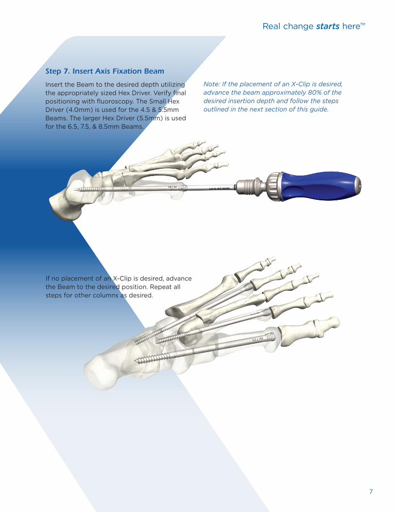
If no placement of an X-Clip is desired, advance the Beam to the desired position. Repeat all steps for other columns as desired.
Step 7. Insert Axis Fixation Beam
Insert the Beam to the desired depth utilizing the appropriately sized Hex Driver. Verify final positioning with fluoroscopy. The Small Hex Driver (4.0mm) is used for the 4.5 & 5.5mm Beams. The larger Hex Driver (5.5mm) is used for the 6.5, 7.5, & 8.5mm Beams.
Note: If the placement of an X-Clip is desired, advance the beam approximately 80% of the desired insertion depth and follow the steps outlined in the next section of this guide.

6
8
Step 1. Attach Targeting Guides
To utilize an X-Clip with an Axis Beam, advance the Beam approximately 80% of the desired insertion depth.
Large Targeting Guide (works with the 6.5, 7.5 & 8.5 Beams) Slide the Drill Guide Portal onto the Targeting Guide (arrow towards the head of the beam). Advance the Portal to the desired Beam length.
Slide the Targeting Guide over the 3.2mm Guidewire and fully seat within the internal hex of the Beam.
Axis Beam Technique for X-Clip Placement
Small Targeting Guide (works with the 4.5 & 5.5mm Beams)
Slide the Drill Guide Portal onto the Targeting Guide (arrow towards the head of the beam). Advance the Portal until to desired Beam length.
Slide the Targeting Guide over the 2.0mm Guidewire taking care to mate the beam with the external coupler. This coupler will engage the head of the beam and is locked into place by rotating the coupler in a clockwise fashion.
Drill Guide Portal

9
C:100M:60Y:7K:1
PMS:2935
C:0M:25Y:100K:0
PMS:123
C:59M:42Y:45K:10
PMS:444
C:92M:66Y:43K:29
PMS:302
MEDICAL Font: Gotham Light 116%, 100 Kernwith .371 case stroke, 13.4° skew
Tagline Font: Gotham Book, Gothic Medium Italic
Step 2. Drilling for the X-Clip
Insert the appropriately sized Drill Guide through the Drill Guide Portal. Make an incision and dissect down to bone taking care to resect the soft tissue directly under the Drill Guide. Advance the Drill Guide down to bone.
Utilizing a wire driver, advance the appropriately sized Drill Pin to the desired depth of X-Clip leg length. To avoid interference, use the Short Drill Pin for the first hole and the Long Drill Pin for the second hole. Verify the position of the Drill Pins with fluoroscopy in both the AP and lateral views. The tip of the Drill Pins should coincide with the desired X-Clip length and should be positioned on either side of the Beam.
Drill Pins straddle the Axis Beam guidewire
4.5mm Gold Small Drill Pin
5.5mm Green Small Drill Pin
6.5mm Blue Large Drill Pin
7.5mm Magenta Large Drill Pin
8.5mm Purple Large Drill Pin
Drill Guide Size Color Drill Pin Size

10
Placement of Plate Screws General Technique
Step 2. Drilling for the X-Clip (Continued)
Note: To measure for the leg length of the X-Clip, remove the Drill Guide and measure the Long Drill Pin with the Cannulated Depth Gauge by placing it over the Drill Pin and down to bone. You will need to subtract 100 from the measurement. For example if the Depth Gauge reads 130, select the X-Clip with 30mm leg length.

11
C:100M:60Y:7K:1
PMS:2935
C:0M:25Y:100K:0
PMS:123
C:59M:42Y:45K:10
PMS:444
C:92M:66Y:43K:29
PMS:302
MEDICAL Font: Gotham Light 116%, 100 Kernwith .371 case stroke, 13.4° skew
Tagline Font: Gotham Book, Gothic Medium Italic
Placement of Plate Screws General Technique
Step 3. X-Clip Insertion
Load the selected X-Clip onto the Clip Inserter with the flat side of the bridge of the X-Clip onto the Clip inserter. Turn the knob at the top of the Inserter clockwise to secure X-Clip, ensuring that the legs are loaded parallel to the Inserter with the bridge of the X-Clip centered in the Inserter.
Flat side into the clip inserter
that the legs are loaded parallel to the Inserter with the bridge of the X-Clip is centered in the Inserter.
Remove the Drill Pins and the Drill Guide from the Drill Portal and deliver the X-Clip through the Drill Portal into the pre-drilled holes
Note: the arrow on the Inserter should match the direction of the arrow on the Drill Portal.

12
Step 3. X-Clip Insertion (Continued)
Advance the X-Clip into the pre-drilled holes without fully seating it. Release the X-Clip from the Inserter by turning the Inserter’s knob counter-clockwise.
Slide the Portal and the Inserter away from the Beam and off of the Targeting Guide.
Remove the Targeting Guide from the Beam and tamp the X-Clip until it is fully seated using the end of the X-Clip Inserter.

13
C:100M:60Y:7K:1
PMS:2935
C:0M:25Y:100K:0
PMS:123
C:59M:42Y:45K:10
PMS:444
C:92M:66Y:43K:29
PMS:302
MEDICAL Font: Gotham Light 116%, 100 Kernwith .371 case stroke, 13.4° skew
Tagline Font: Gotham Book, Gothic Medium Italic
Step 4. Final Position of Axis Beam
Verify the positioning of the X-Clip to the Axis Beam with fluoroscopy. Advance the Axis Beam through the X-Clip compressing the fusion site. Advance till the head of the beam is countersunk to the metaphysis of the metatarsal.
Axis Beams also provide an ideal option for hindfoot stabilization challenges.

14
Axis Beam and X-Clip Removal Instructions
It is recommended to remove the Axis Beam prior to removing the X-Clip:
Axis Beam Removal
• Clear any tissue ingrowth from the Axis Beam
4.5 & 5.5mm Beams: • Insert the Small Removal Driver (4.0mm Hex) into the Axis Beam and back out the Beam by turning counter-clockwise.
The Small Removal Tool can be inserted
through the Removal Driver and threaded
into the head of the beam to capture the
internal threads and provide assistance
during the removal process.
• Advance the X-Clip into the pre-drilled holes without fully seating it. Release the X-Clip from the Inserter by turning the Inserter’s knob counter-clockwise.
6.5, 7.5 & 8.5mm Beams:
• Insert the Large Removal Driver (5.5mm Hex) into the Axis Beam and back out the Beam by turning counter-clockwise.
The Large Removal Tool can be inserted
through the Removal Driver and threaded
into the head of the beam to capture
the internal threads and provide
assistance during the removal process.
X-Clip Removal
• Expose the bridge of the X-Clip
• If the X-Clip is recessed, use an elevator to lift the implant bridge
• Utilize forceps to remove the implant

15
C:100M:60Y:7K:1
PMS:2935
C:0M:25Y:100K:0
PMS:123
C:59M:42Y:45K:10
PMS:444
C:92M:66Y:43K:29
PMS:302
MEDICAL Font: Gotham Light 116%, 100 Kernwith .371 case stroke, 13.4° skew
Tagline Font: Gotham Book, Gothic Medium Italic
Axis Beam and X-Clip Removal Instructions
The Axis Beam Implant can be supplemented by the Axis Plate Charcot System implants based on surgeon preference. Axis Plates have been designed to allow for the option to be placed around an Axis Charcot Beam. The plate screws allow for a 30o cone of angulation. Take care to place plate screws away from the already placed Axis Beam. Ensure proper utilization of the Drill Guides in conjunction with fluoroscopy to avoid screw collision.
For more information, refer to the Axis Plate MAPP Surgical Technique, or contact Extremity Medical.
Caging the Beam with Axis Plates
Axis Plantar Plate Metatarsal to Talus Implant
Axis Plantar-medial Plate with Talar Wrap
16
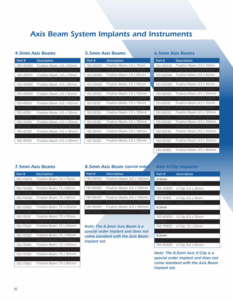
Axis Beam System Implants and Instruments
4.5mm Axis Beams
Part # Description
6.5mm Axis Beams
130-65070130-65075130-65080130-65085130-65090130-65095130-65100130-65105130-65110130-65115130-65120130-65125130-65130130-65135130-65140130-65145130-65150130-65155130-65160
Fixation Beam, 6.5 x 70mmFixation Beam, 6.5 x 75mmFixation Beam, 6.5 x 80mmFixation Beam, 6.5 x 85mmFixation Beam, 6.5 x 90mmFixation Beam, 6.5 x 95mmFixation Beam, 6.5 x 100mmFixation Beam, 6.5 x 10⁵mmFixation Beam, 6.5 x 110mmFixation Beam, 6.5 x 115mmFixation Beam, 6.5 x 120mmFixation Beam, 6.5 x 125mmFixation Beam, 6.5 x 130mmFixation Beam, 6.5 x 135mmFixation Beam, 6.5 x 140mmFixation Beam, 6.5 x 145mmFixation Beam, 6.5 x 150mmFixation Beam, 6.5 x 155mmFixation Beam, 6.5 x 160mm
7.5mm Axis Beams
130-75070130-75075130-75080130-75085130-75090130-75095130-75100130-75105130-75110130-75115130-75120130-75125130-75130130-75135130-75140130-75145130-75150130-75155130-75160
Fixation Beam, 7.5 x 70mmFixation Beam, 7.5 x 75mmFixation Beam, 7.5 x 80mmFixation Beam, 7.5 x 85mmFixation Beam, 7.5 x 90mmFixation Beam, 7.5 x 95mmFixation Beam, 7.5 x 100mmFixation Beam, 7.5 x 10⁵mmFixation Beam, 7.5 x 110mmFixation Beam, 7.5 x 115mmFixation Beam, 7.5 x 120mmFixation Beam, 7.5 x 125mmFixation Beam, 7.5 x 130mmFixation Beam, 7.5 x 135mmFixation Beam, 7.5 x 140mmFixation Beam, 7.5 x 145mmFixation Beam, 7.5 x 150mmFixation Beam, 7.5 x 155mmFixation Beam, 7.5 x 160mm
Part # Description
Part # Description
Axis X-Clip Implants
X-Clip, 4.5 x 15mmX-Clip, 4.5 x 20mm
X-Clip, 5.5 x 15mmX-Clip, 5.5 x 20mm
X-Clip, 6.5 x 25mmX-Clip, 6.5 x 30mm
X-Clip, 7.5 x 25mmX-Clip, 7.5 x 30mm
X-Clip, 8.5 x 25mmX-Clip, 8.5 x 30mm
Part # Description
8.5mm Axis Beam (special order)
Part # Description
130-45060 Fixation Beam, 4.5 x 60mm 130-45065 Fixation Beam, 4.5 x 65mm 130-45070 Fixation Beam, 4.5 x 70mm 130-45075 Fixation Beam, 4.5 x 75mm 130-45080 Fixation Beam, 4.5 x 80mm 130-45085 Fixation Beam, 4.5 x 85mm 130-45090 Fixation Beam, 4.5 x 90mm 130-45095 Fixation Beam, 4.5 x 95mm 130-45100 Fixation Beam, 4.5 x 100mm 130-45105 Fixation Beam, 4.5 x 105mm 130-45110 Fixation Beam, 4.5 x 110mm 130-45115 Fixation Beam, 4.5 x 115mm 130-45120 Fixation Beam, 4.5 x 120mm 130-45125 Fixation Beam, 4.5 x 125mm 130-45130 Fixation Beam, 4.5 x 130mm 130-45135 Fixation Beam, 4.5 x 135mm 130-45140 Fixation Beam, 4.5 x 140mm
130-85100 Fixation Beam, 8.5 x 100mm130-85110 Fixation Beam, 8.5 x 110mm130-85120 Fixation Beam, 8.5 x 120mm130-85130 Fixation Beam, 8.5 x 130mm130-85140 Fixation Beam, 8.5 x 140mm130-85150 Fixation Beam, 8.5 x 150mm130-85160 Fixation Beam, 8.5 x 160mm130-85170 Fixation Beam, 8.5 x 170mm
4.5mm 130-45915130-459205.5mm130-55915130-559206.5mm130-65925130-659307.5mm130-75925130-759308.5mm130-85925130-85930
5.5mm Axis Beams
130-55070130-55075130-55080130-55085130-55090130-55095130-55100130-55105130-55110130-55115130-55120130-55125130-55130130-55135130-55140130-55145130-55150
Fixation Beam, 5.5 x 70mmFixation Beam, 5.5 x 75mm Fixation Beam, 5.5 x 80mmFixation Beam, 5.5 x 85mmFixation Beam, 5.5 x 90mmFixation Beam, 5.5 x 95mmFixation Beam, 5.5 x 100mmFixation Beam, 5.5 x 10⁵mmFixation Beam, 5.5 x 110mmFixation Beam, 5.5 x 115mmFixation Beam, 5.5 x 120mmFixation Beam, 5.5 x 125mmFixation Beam, 5.5 x 130mmFixation Beam, 5.5 x 135mmFixation Beam, 5.5 x 140mmFixation Beam, 5.5 x 145mmFixation Beam, 5.5 x 150mm
Part # Description
Note: The 8.5mm Axis Beam is a special order implant and does not come standard with the Axis Beam implant set.
Note: The 8.5mm Axis X-Clip is a special order implant and does not come standard with the Axis Beam implant set.

17
C:100M:60Y:7K:1
PMS:2935
C:0M:25Y:100K:0
PMS:123
C:59M:42Y:45K:10
PMS:444
C:92M:66Y:43K:29
PMS:302
MEDICAL Font: Gotham Light 116%, 100 Kernwith .371 case stroke, 13.4° skew
Tagline Font: Gotham Book, Gothic Medium Italic
Disposable Instruments Reusable Instruments
Part # Description
130-00020130-00032130-00045130-00055130-00065130-00075 130-00085130-00220130-02020130-02025130-02120130-02125
Guidewire, Small (2.0mm)Guidewire, Large (3.2mm)Cannulated Drill, 4.5mmCannulated Drill, 5.5mmCannulated Drill, 6.5mmCannulated Drill, 7.5mm Cannulated Drill, 8.5mmCleaning Brush, 2.0mmShort Drill Pin, SmallLong Drill Pin, SmallShort Drill Pin, LargeLong Drill Pin, Large
Part # Description
Tissue ProtectorRatcheting Handle1/4” Sq.-to-Jacobs AdapterBeaming Sizing Key Removal Tool, SmallRemoval Tool, LargeStarter Awl, SmallStarter Awl, LargeHex Driver, Small (4.0mm)Countersink, SmallHex Driver, Large (5.5mm)Countersink, LargeDepth Gauge, Small (2.0mm)Depth Gauge, Large (3.2mm)Removal Driver, Small (4.0mm)Removal Driver, Large (5.5mm)X-Clip InserterDrill Guide PortalDrill Guide, 4.5mmDrill Guide, 5.5mmDrill Guide, 6.5mmDrill Guide, 7.5mmDrill Guide, 8.5mm Targeting Guide, SmallTargeting Guide, Large
130-00003130-00004130-00005 130-00007130-00025130-00040130-00120130-00132130-00140130-00145130-00155130-00165130-00230130-00232130-00240130-00255130-03300130-03000130-03045130-03055130-03065130-03075 130-03085130-03455130-03678

2797
2797
2797
2797
0086
0086
0086
0086
2797
2797
2797
2797Patent Pending. Extremity Medical®, and Axis Beam® are trademarks of Extremity Medical, LLC.© 2020 Extremity Medical, LLC. All Rights Reserved.
888.499.0079
973.588.8980
ExtremityMedical.com
300 Interpace Parkway, Suite 410 I Parsippany, NJ 07054
C:100M:60Y:7K:1
PMS:2935
C:0M:25Y:100K:0
PMS:123
C:59M:42Y:45K:10
PMS:444
C:92M:66Y:43K:29
PMS:302
MEDICAL Font: Gotham Light 116%, 100 Kernwith .371 case stroke, 13.4° skew
Tagline Font: Gotham Book, Gothic Medium Italic
Real change starts here™
Delivering
a smarter approach for Charcot Period.
C: 96M: 70Y: 7K: 1
C: 60M: 40 Y: 40 K: 100
C: 0M: 25 Y: 100 K: 0
PMS:2935
PMS:123
R: 5G: 9B: 159
R: 255G: 194B: 14
R: 0G: 0B: 5
R: 255G: 255B: 255
055a9f f fc20e 000005 f f f f f f
Osteotomy Wedge: Eras Demi 100%, 100 Kern
Axis Beam Font: Eras Demi/Medium 100%, 100 Kern
® Eras Medium Axis BeamCharcot Fixation System
LBL-130-99102-EN Rev C 12/2020