
A simulation-based method for effective workface planning of...
21
Full Terms & Conditions of access and use can be found at http://www.tandfonline.com/action/journalInformation?journalCode=rcme20 Download by: [Purdue University Libraries] Date: 04 November 2017, At: 02:01 Construction Management and Economics ISSN: 0144-6193 (Print) 1466-433X (Online) Journal homepage: http://www.tandfonline.com/loi/rcme20 A simulation-based method for effective workface planning of industrial construction projects Di Hu, Yasser Mohamed, Hosein Taghaddos & Ulrich (Rick) Hermann To cite this article: Di Hu, Yasser Mohamed, Hosein Taghaddos & Ulrich (Rick) Hermann (2017): A simulation-based method for effective workface planning of industrial construction projects, Construction Management and Economics, DOI: 10.1080/01446193.2017.1390241 To link to this article: http://dx.doi.org/10.1080/01446193.2017.1390241 Published online: 26 Oct 2017. Submit your article to this journal Article views: 21 View related articles View Crossmark data
Transcript of A simulation-based method for effective workface planning of...

Full Terms & Conditions of access and use can be found athttp://www.tandfonline.com/action/journalInformation?journalCode=rcme20
Download by: [Purdue University Libraries] Date: 04 November 2017, At: 02:01
Construction Management and Economics
ISSN: 0144-6193 (Print) 1466-433X (Online) Journal homepage: http://www.tandfonline.com/loi/rcme20
A simulation-based method for effective workfaceplanning of industrial construction projects
Di Hu, Yasser Mohamed, Hosein Taghaddos & Ulrich (Rick) Hermann
To cite this article: Di Hu, Yasser Mohamed, Hosein Taghaddos & Ulrich (Rick) Hermann (2017):A simulation-based method for effective workface planning of industrial construction projects,Construction Management and Economics, DOI: 10.1080/01446193.2017.1390241
To link to this article: http://dx.doi.org/10.1080/01446193.2017.1390241
Published online: 26 Oct 2017.
Submit your article to this journal
Article views: 21
View related articles
View Crossmark data

ConstruCtion ManageMent and eConoMiCs, 2017https://doi.org/10.1080/01446193.2017.1390241
A simulation-based method for effective workface planning of industrial construction projects
Di Hua, Yasser Mohamedb , Hosein Taghaddosc and Ulrich (Rick) Hermanna
aengineering department, PCL industrial Management inc., edmonton, Canada; bdepartment of Civil and environmental engineering, university of alberta, edmonton, Canada; cschool of Civil engineering, College of engineering, university of tehran, tehran, iran
ABSTRACTThe generation of well-defined and moderately sized field installation work packages for the construction workforce, referred to as workface planning, has been recently employed to plan large-scale industrial construction projects under tight schedules. However, traditional CPM-based scheduling of several thousand work packages (e.g. 5000 activities multiply by 10 work packages per activity on average) is a tedious, error prone process. Defining proper logics and controlling congestion among work packages crossing several work areas, and also effective resource allocation over time are other major challenges in workface planning. This paper presents a novel simulation-based framework to implement workface planning for large-scale industrial construction projects. This framework proposes a time-stepped discrete event simulation-based modelling for dynamic resource allocation based on congestion and other constraints on the job site. The proposed method is demonstrated and tested against traditional CPM-based solutions based on an actual case study.
1. Introduction
Mega projects in Heavy Industrial industry pose huge chal-lenges for general contractors due to its sheer size and complexity. The Alberta Economic Development Authority (AEDA 2004) summarized a few figures for mega projects based on the oil sands projects built in the province of Alberta, Canada. For a project of $2.5 billion, it requires around 3.5 million engineering man-hours and 15 million construction man-hours and generates 40,000 to 50,000 design drawings and 10,000 to 20,000 vendor and shop drawings.
Workface Planning (WFP) was introduced by Construction Owners Association of Alberta (COAA) in the last decade to enhance planning and organizing mega construction projects. WFP can be defined as the process of breaking down the project into well-defined Field Installation Work Packages (FIWP) to facilitate field crews to perform quality work safely and efficiently. The size of FIWP in one discipline usually does not exceed one rotation of work, ranging from 5 to 10 working days (Ryan 2009). The project team must review the FIWPs to make sure all perquisites are ready prior to releasing them on the job site (Construction Industry Institute 2011).
Implementing WFP on mega-projects with traditional CPM-based software (e.g. Primavera, Microsoft Project) is an onerous exercise as the schedule generally involves 2000 to 6000 activities, each of which can be broken into five to thirty work packages. The addition of work pack-ages to the schedule is an on-going exercise since work packages are built about four weeks before construction begins on field. The schedule will continuously grow in activity count as work packages are added since large scale projects take several years to execute. Some other major limitations of CPM scheduling to implement WFP include fixed logic among activities, fixed activity durations and fixed resource allocation levels. This rigidity is not a pre-cise presentation of how FIWPs are executed on the job site. More often, fictitious logics are entered as hard con-straints among FIWPs, while most of these logics are soft constraints that can be variable over time. For example, the level of congestion in often manipulated by an added log-ics to delay some of FIWPs. Based on the experience of the authors in industrial projects, the traditional CPM method of scheduling work packaging has several key drawbacks which led to this research project.
(1) Variable logic among work packages resulting from sharing resources (e.g. working crews) can-not be automated.
© 2017 informa uK Limited, trading as taylor & Francis group
KEYWORDSWorkface planning; schedule; site congestion; resource constraints; discrete event simulation
ARTICLE HISTORYreceived 8 February 2017 accepted 22 september 2017
CONTACT Yasser Mohamed [email protected]
Dow
nloa
ded
by [
Purd
ue U
nive
rsity
Lib
rari
es]
at 0
2:01
04
Nov
embe
r 20
17

2 D. HU ET AL.
piping and steel members) in a factory like shop environ-ment off-site. Some of these fabricated components are shipped directly to site for final installation, others are syn-thesized with other pre-fab components into a unit called module. A module is a building block for a pipe rack or a plant that includes a steel structure, piping, equipment, cable tray, instruments and other electrical components. Modules are sized within the limitations of transportation so that they could be shipped from assembly yards to the construction site. The proportion of shop fabrication and module assembly used in industrial projects has signifi-cantly increased over the past 20 years (Haas et al. 2000).
In a perfect scenario, both shop fabrication and module assembly should be driven by site construction. However, during the course of construction, the site schedule is prone to changes due to many factors such as scope/design changes, site conditions or constructability issues. This variability originates at the end of the supply chain and ripple back to all proceeding stages (Wang 2006). It mani-fests in the form of rush orders, change orders or order can-celations (Figure 1) and causes rework, work stoppage and priority change in shop fabrication and module assembly, which in turn disrupt the site construction in the form of late or out-of-sequence supply. The disruption is further amplified when the supply of IFC (Issue for Construction) drawings and raw materials are unreliable.
Fast tracking is another contributor to variability. Fast tracking forces overlap between design, procurement, fab-rication, module assembly and site installation. As a result, pre-fabrication, pre-assembly and even site construction start well before the design is completed. As project pro-gresses, the incomplete design is usually translated into a large number of drawing revisions, which in turn disrupt shop fabrication, module assembly and site construction (Williams 1995).
Uniqueness in industrial project components (especially in piping) makes it extremely difficult to mitigate the late
(2) Resource level during the execution of work packages is variable and their durations are not fixed.
(3) Work packages do not necessarily require the full size crew to perform the work.
(4) Limits on how many and which trades can simultaneously work in a work area cannot be performed.
(5) Congestion issue is challenging to be controlled particularly if work packages cross several work areas.
This paper presents a novel simulation-based framework to implement workface planning for large-scale industrial construction projects. This framework dissects work pack-ages into segments based on time unit (i.e. hour, day, week or month) and simulate the execution of these segments by using time-stepped simulation. Such resource alloca-tion not only satisfies the resource limit at certain time, but also limits congestion at certain work area based on work package priorities. FIWPs are allowed to be interrupted and also changed in durations given the resource limits and task priorities. Priority is an input to the simulation which can be either calculated based on heuristics or over-ridden by managers/superintendents. The simulation also respects hard constraints such as predecessor/successor dependency, imposed start/finish dates, work calendars for different trades.
2. Industrial projects supply chains
Many of heavy industrial projects have complex supply chains. They are built in remote areas where local labour availability is not sufficient and a substantial workforce needs to be relocated from somewhere else. The on-site labour cost could be very expensive. One solution to this is to pre-fabricate most construction components (e.g.
WorkArea100 WorkArea101
WorkArea102 WorkArea103
WP1
WP5
WP4
WP2 WP
3
Figure 1. Work areas and congestion limit.
Dow
nloa
ded
by [
Purd
ue U
nive
rsity
Lib
rari
es]
at 0
2:01
04
Nov
embe
r 20
17

CONSTRUCTION MANAGEMENT AND ECONOMICS 3
or out-of-sequence supply from fabrication shops or mod-ule yards. A petroleum refinery can require as many as 10,000 piping inventory codes, each of which represents a unique piping component (Wyss 2009).
Based on authors’ experience, high level of variabil-ity instantly changes the “workable” work fronts for site crews and requires that site mangers/superintendents/planners quickly respond to the changes and make adjust-ments accordingly. This is performed by site management through detailed weekly lookahead schedules modified daily as needed. It is usually done through re-direct-ing/re-distributing limited work force to focus on those “workable” and “high priority” work fronts. For example, resources are released from in-progress work packages due to pending issues (e.g. Request for Information) and are re-allocated to other “workable” work packages. Other times, priority on work packages changes to reflect the new construction sequence. Work packages can be started with a reduced resource level. Work packages with higher priority more likely receive full amount of resources while work packages with lower priority end up with a lower resource level or are completely delayed. As a result, their durations are either shortened or extended and the sched-uled dates are either advanced or delayed. The resource level is also not invariable during the execution of work packages.
The resource limit, the total available resource, is often not fixed at the same level throughout project duration. A resource (i.e. especially manpower) usually starts at a relatively low level, peaks somewhere in the middle of the project and gradually declines towards the end. The avail-ability of resources can vary from one period to another and be at different levels during the project life cycle. This is usually referred to as Time-dependent Resource Availability (Hartmann 2013, Castro et al. 2014).
Work packages in industrial projects often are linear and cross multiple work areas, which tend to cause con-gestion issues. Workspace congestion can be affected by different factors such as number of workers in a given work area, product space, equipment space, material storage space, space used by temporary structures, space for workers and equipment paths (Akinci et al. 2002, Mallasi 2006). Congestion in this paper is strictly limited to the number of workers who are working in the same work area during the same period of time. Congestion is a common issue in mega projects when many work pack-ages are performed concurrently in the same area. Since congestion diminishes productivity and increases the risk of safety incidents, it is necessary to impose congestion constraints on these areas so that it can be controlled. This congestion constraint, in turn, affects the amount of resources (especially workers) that could be allocated to work packages in the area. Work Packages are often
not constrained to one work area, thus a mechanism called Work-Area-Work-Package was built to handle this issue.
Both resource availability level and resource utilization level can vary over time, even in the middle of the exe-cution of work packages. This issue has been dealt with in the form of morning superintendent meetings where superintendents and managers sit together to review the current project status and allocate or re-allocate the lim-ited resource at hand to mitigate the negative effect of changes on the project schedule.
3. Literature review
Traditional critical-path-method- (CPM) based project scheduling techniques (e.g. Program Evaluation and Review Technique, Activity-On-Node, Activity-On-Arrow and Precedence Diagram Method) are limited in terms of practicality for their unrealistic assumption that resources are unlimited. Recognition of this limitation motivated intensive research in regards to the resource-constrained project scheduling problem (RCPSP). There are two major topics in this domain: resource allocation and resource lev-elling. The former aims to find the shortest project duration within the resource availability constraints, while the lat-ter seeks to reduce the fluctuation in resource usage with assumptions such as unlimited resource availability and fixed project duration (Hegazy 1999). Since this research is more related to the former topic, literature related to resource allocation is reviewed herein.
Many researchers have attempted to formulate the RCPSP as a mathematical programming problem using various optimization techniques such as linear program-ming, branch-and-bound, and enumerative branch-and-cut (Karshenas and Haber 1990, Demeulemeester 2002, Jiang and Shi 2005). These techniques can only find a global optimal solution, if the RCPSP problem is solvable. However, these techniques are computationally imprac-tical for most real-life projects (Moselhi and Lorterapong 1993, Hegazy 1999, Kim and de la Garza 2005).
Another approach to tackle the RCPSP problem is through heuristic techniques. Heuristics provide criteria for prioritizing concurrent work packages that are com-peting for the same resource. Commonly used heuristics include the least total float (LTF), the minimum latest finish (LFT) and resource scheduling method (RSM) (Davis and Patterson 1975). Moselhi and Lorterapong (1993) devised another heuristic technique, “least impact”, which allocates resources to a set of activities rather than to an individual activity, as in most heuristic techniques. Lu and Li (2003) proposed a new heuristic called “work content” and argue it has comparable performance with LTF in terms of finding the shortest project duration.
Dow
nloa
ded
by [
Purd
ue U
nive
rsity
Lib
rari
es]
at 0
2:01
04
Nov
embe
r 20
17
4 D. HU ET AL.
relationships (such as Start-to-Start and Finish-to-Finish) into Finish-to-Start. However, as for resource allocation, it holds the same deterministic view point.
Jobsite congestion has been approached mainly in two different ways: (1) space scheduling or space-time conflict, and (2) productivity loss due to site congestion. The former takes space as one of the pre-conditions (as a resource constraint) to perform a work package and returns a space-loaded construction schedule (Beliveau and Thabet 1994, Riley and Sanvido 1997, Tommelein and Zouein 2001, Akinci et al. 2002). A main goal of this line of research is to discover the mapping between space requirements of work packages and the physical space in 2D or 3D format, and then to detect and resolve the space conflict between work packages in close proxim-ity. Recent work related to this line of research includes Location Based Scheduling (LBS). In this work, physical locations of activities are included in the planning and scheduling process. This method allows more control of the workflow to maintain continuity of work for differ-ent crews and to eliminate interference of trades in the same location, which consequently improves production efficiency (Lowe et al. 2012). It should be noted that LBS terminology that describes construction activities and workspace refer to concepts very similar to ones used in this paper. For example, LBS tasks refer to the same con-cept of work package and LBS locations refer to the same concept of work area. However, there is another type of congestion – overcrowding. It only reflects a degree of how crowded a work area is but not necessarily amounts to a space conflict. Jobsite crowding is believed to be one of the major causes of productivity loss and safety haz-ards (Nandakumar and Ahuja 1985, AbouRizk et al. 1993, Beliveau and Thabet 1994, Ovararin and Popescu 2001). Many researchers attempted to quantify the impact of site congestion on crew productivity (Thomas and Smith 1990, AbouRizk et al. 1993, Beliveau and Thabet 1994, Horner 1995, Ovararin and Popescu 2001).
Few researchers attempted to incorporate the impact of jobsite overcrowding into the schedules of work pack-ages. Zouein and Tommelein (2001) suggested that space congestion issue can be solved, in addition to delaying the start of a work package, by lowering the resource level of work packages, believing that the space requirement can be reduced as its resource level declines. Although recognizing the relationship between the resource level and the degree of congestion, they did not fully make use of dynamic resource allocation. Instead, they assumed that the resource level, whether it is decreased or at the nor-mal level, is determined at the start of a work package and stays constant throughout its duration. Thabet and Beliveau (1994) also recognized that work space crowding lengthens the duration of work packages and attempted
Meta-heuristic-based project scheduling techniques became popular recently. These algorithms perform sto-chastic searches on populations of solutions which evolve over a number of iterations (Lu et al. 2008, Elbeltagi et al. 2005). Genetic algorithm (GA) has also been adopted to solve RCPSP problems (Chan et al. 1996, Hegazy 1999, Kandil and El-Rayes 2006). Unlike mathematic and heu-ristic techniques, these algorithms are usually designed to achieve more than one objective simultaneously (e.g. the minimum project duration, the least resource utiliza-tion variation and the least cost). GA has been used widely to optimize various construction problems, such as fleet configuration for earthmoving (Marzouk and Moselhi 2004), and location selection for crane lifting (Al-Hussein et al. 2005). GA limitations have also been identified, e.g. long processing time and tendency to be trapped in local optima (Elbeltagi et al. 2005, Ng and Zhang 2008). This motivated researchers to explore other meta-heuristic techniques. Particle swarm optimization (PSO) and ant colony optimization (ACO) are the two algorithms recently introduced to the construction scheduling domain (Lu et al. 2008, Ng and Zhang 2008, Christodoulou 2010).
Most previous RCPSP research is focused on finding more efficient and more effective scheduling optimiza-tion techniques. Scheduling optimization aside, they all assume that the work package can only start when all required resources are available throughout its duration and that, once captured, the resource levels stay constant for the duration of the work package. For example, if a piping work package requires a crew of 10 pipe fitters to perform the work, it is allowed to start only when there are 10 or more pipe fitters available. Otherwise, it would be simply delayed or interrupted until this condition is satisfied again. In practice, the work package might be carried out even if there are only 8 pipe fitters available. The resource level allocated to a work package could be any value within the range (minimum, normal, and max-imum). In addition, resource level allocated to a work package could also change during the course of execu-tion. For example, when a work area is congested, the number of skilled workers assigned to work packages might be reduced to alleviate the congestion. Or, skilled workers might be diverted from lower priority, in-progress work packages to higher priority ones so that they can be started. The dynamic characteristics of resource allocation, due to changing site conditions, are ignored in most pre-vious RCPSP research, although it may have substantial impact on work packages’ performance and need to be considered in the scheduling process.
Hegazy and Menesi (2010) proposed a new critical path analysis method called Critical Path Segment (CPS), which decompose activities into a group of segments based on days. This method converts the complicated precedence
Dow
nloa
ded
by [
Purd
ue U
nive
rsity
Lib
rari
es]
at 0
2:01
04
Nov
embe
r 20
17
CONSTRUCTION MANAGEMENT AND ECONOMICS 5
package. Figure 1 shows a situation where several work packages take place concurrently in the same work area (e.g. WorkArea101) and a work package (e.g. WP2) can extend across several work areas (e.g. WorkArea100, 101 and 102). As a result, the execution of WP2 should comply with both resource limit and congestion constraints of all three work areas that it crosses.
Congestion constraint can be treated as a type of resource that is expressed as how many skilled workers can be present in the same work area. For example, assume that WP2 normally requires 10 skilled workers. However, due to the congestion status of WorkArea101, it could only get work space to accommodate 8 skilled workers. This can be modelled as it captures 8 skilled workers from a certain trade and meanwhile takes work space for 8 skilled workers from WorkArea101. A dilemma arises when WorkArea100 and WorkArea102 differ from WorkArea101. For example, WorkArea100 allows 10 skilled workers while WorkArea102 can only accommodate 7 skilled workers. Since WP2 also crosses these two work areas, it is then inaccurate to assign 8 skilled workers to the entire work package WP2 (Figure 2(a)). When WP2 is being performed in WorkArea101, it does not involve congestion limits in WorkArea100 and WorkArea102, and vice versa.
Figure 2(b) presents a new way of implementing con-gestion constraint. Work packages are further broken down into smaller elements called Work-Area-Work-Packages (WAP). Each WAP represents a portion of the work package in a specific work area. In this way, congestion constraints can act, respectively, on individual WAPs instead of on the whole work package. Since work packages are already at the lowest level of project planning and scheduling, WAPs need to be automatically created before simulation com-mences. The creation of WAPs can be viewed as part of pre-simulation data processing. The details and assump-tions about the creation process are described as follows.
4.1. Definition of WAP
In order to define WAPs, it is necessary to know in which work area(s) a work package is going to take place. Each work package/work area pair defines a WAP. A link is estab-lished between WAP and its parent work package. In this way, WAPs have access to the properties of their parent work packages, e.g. discipline, total man-hours, total quan-tity, unit of measurement, etc.
4.2. Size of WAP
The size of WAPs is roughly derived from dividing the total man-hours (or total quantity) of the parent work package by the number of work areas it crosses. This is merely an approximation, but accurate enough for the
to reflect this in the schedules of work packages. However, they suggested that instead of lowering resource level, the production rate should be reduced, due to multiple work packages taking place concurrently in the same work area, and consequently, increased congestion. This means that work packages can still hold the normal amount of resources, regardless of how crowded the work area is, and only get penalized by decreased production rates. In reality, however, this is not the case, since overcrowding not only causes reduction in productivity, but also brings about safety hazards and should be restricted with a max-imum limit.
A gap exists between the project-scheduling-re-lated research and industry practice. Little attention has been paid to the dynamic nature of resource availability, resource requirement and resource level of work packages. Instead, a deterministic point of view dominates most pre-vious research. Meanwhile, jobsite overcrowding is seldom considered and integrated during the scheduling process.
Since absolute schedule optimization is not the focus of this paper, heuristic technique is selected to implement in the proposed framework.
Heuristic-based resource constrained project sched-uling has two components: a scheduling scheme and a priority rule (Kolisch 1996). Scheduling scheme can be categorized into two different modes: serial scheduling scheme and parallel scheduling scheme. Serial scheduling scheme determines a sequence of activities, ordered by their priority (based on whatever priority rule is used). This sequence of activities is then scheduled one at a time and at the earliest time when both dependency and resource availability constraints can be met. Parallel scheduling scheme, on the other hand, assigns and releases resources at every time unit. Likewise, at the beginning of each time unit, a list of eligible activities (those whose predecessors have been completed) is updated and ordered by prior-ity. Activities that create no resource over-allocation are scheduled and others are delayed or interrupted. This pro-cedure repeats until all activities are scheduled. The major difference between the two scheduling schemes is that the serial mode releases resources only at the completion of activities while the parallel mode releases resources at the end of every time unit (Lu and Li 2003). Considering the flexibility that is required by dynamic resource allocation in this study, the parallel scheduling scheme is used.
4. Proposed simulation-based framework
Congestion issues are associated with “work area,” a con-cept that does not directly correspond to work packages. This is especially the case in industrial projects where many work packages are linear and cross a number of work areas, while each work area might involve more than one work
Dow
nloa
ded
by [
Purd
ue U
nive
rsity
Lib
rari
es]
at 0
2:01
04
Nov
embe
r 20
17

6 D. HU ET AL.
5. Time-stepped discrete event simulation (DES)
The heuristic resource allocation approach can be imple-mented and automated through the use of DES. Simulation has long been used to model and analyse various construc-tion processes, with the objective of improving long-term performance. For the last two decades, it has increasingly been used for planning and scheduling day-to-day oper-ations. It is usually referred to as simulation-based sched-uling (Senior and Halpin 1998, Lu et al. 2008, Mohamed et al. 2007, Taghaddos et al. 2012). Compared to traditional CPM method, DES is able to explicitly model resource inter-actions such that the resulting schedule is automatically levelled to the availability of resources. Another major advantage of using DES is that it provides a cost-effective laboratory environment where various alternatives can be tested and compared and the best one can be selected, without interrupting the real system. Many researchers have investigated the use of DES to solve construction planning and scheduling problems (Martinez et al. 1994, Senior and Halpin 1998, Zhang et al. 2002, Song and
work-area-work-package level. For example, sizes of pip-ing WAPs can be determined by the length of pipe spools or the number of ISOs in each work area.
4.3. Sequence of WAP
WAPs inherit all precedence relationships from parent work packages. For example, if work package A is a pre-decessor to work package B, all WAPs of A (A1, A2, …, An) are predecessors to all WAPs of B (B1, B2, …, Bn). Both the type of precedence relationship and the time lag remain the same. No sequence exists between WAPs from the same work packages.
This study assumes that each WAP is performed con-tinuously once it has been started. However, on the work package level, child WAPs are not necessarily performed in a continuous fashion. This assumption makes sense in the context of industrial projects, since stoppage between WAPs can happen due to the time required to set up scaf-folding in each work area when the work takes place at higher elevations.
10
WP2
WP2
(a) Traditional way of implementing congestion limit
WP2 WP2
WorkArea100 WorkArea101 WorkArea102
8
6
4
2
10
8
6
4
2
10
8
6
4
2
1 2 3 4 5 6 7 8 9 101 2 3 4 5 6 7 8 9 10 1 2 3 4 5 6 7 8 9 10
Original Plan
Congestion LimitCongestion Limit
Congestion Limit
After CongestionOriginal Plan
After Congestion
Original Plan
After Congestion
10
WP2
WP2
Sub work package@ WorkArea100
Sub work package@ WorkArea101
Sub work package@ WorkArea102
(b) WorkAreaWorkPackage
WP2 WP2
WorkArea100 WorkArea101 WorkArea102
8
6
4
2
10
8
6
4
2
10
8
6
4
2
1 2 3 4 5 6 7 8 9 101 2 3 4 5 6 7 8 9 10 1 2 3 4 5 6 7 8 9 10
Original Plan
Congestion LimitCongestion Limit
Congestion Limit
After CongestionOriginal Plan
After Congestion
Original Plan
After Congestion
Figure 2. Work-area-work-package and congestion constraint.
Dow
nloa
ded
by [
Purd
ue U
nive
rsity
Lib
rari
es]
at 0
2:01
04
Nov
embe
r 20
17

CONSTRUCTION MANAGEMENT AND ECONOMICS 7
them considering the limited availability and congestion conditions in each work area; (4) advance the simulation to the next time step unless all WAPs have been completed already or a pre-defined time limit has been reached.
6. Identify eligible work packages
Work packages should not be released to field until all the preconditions have been met. It is necessary to check the eligibility of every work package before it can be sched-uled. This also applies to WAPs, each of which represents a portion of its parent work package. Various constraint checks are built into the simulation, including predeces-sor status check, time constraints check, and prerequisites check, as defined below.
6.1. Predecessor WAPs check
It is the precedence relationships that drive the schedule to move forward. As predecessor WAPs progress or are com-pleted, the succeeding WAPs become eligible to be exe-cuted. The proposed method incorporates all four types of precedence relationships: (1) start-to-start (SS); (2) start-to-finish (SF); (3) finish-to-start (FS); and (4) finish-to-finish (FF). Both positive and negative time lags are allowed to complement the four relationship types in order to model the logic relationship between WAPs. More than one rela-tionship can exist between a pair of WAPs.
6.2. Time constraint check
A work package may have time constraints that govern its start time or/and finish time. These constraints also apply to child WAPs of this work package. Simulation converts the current simulation time into date-time format and compares with these constraints to determine the eligi-bility of WAPs.
6.3. Prerequisite check
Material and drawing availability are the most frequent reasons to delay work packages. In fast-tracked industrial projects, construction and procurement starts way before the design is completed. Since scope is either undeter-mined or prone to change, the delivery of material and drawings becomes the major issue to hamper project pro-gress. The start of WAPs is checked against delivery dates of required material and drawings.
Only WAPs that have successfully passed all three checks are schedulable or eligible. Others are sent back to the WAP pool, and checked in future time units.
AbouRizk 2006, Mohamed et al. 2007, Hu and Mohamed 2010, Taghaddos et al. 2012).
However, previous research depends heavily on the event-driven type of discrete event simulation (DES). Event-driven DES uses two events (start and/or end event) to represent the beginning and the completion of a work package. Once the duration is sampled from a statistic dis-tribution, the execution of the work package (including resource level) is determined and stays the same through-out its duration. It then skips the interval between these two events. Time-stepped simulation is another type of DES where time advances in equal increments. At each step, the event list is checked to see whether an event is scheduled to occur. If yes, the system state is updated accordingly; otherwise, the simulation advances to the next time step and the system state remains unchanged. Future events are also scheduled in response to events occurring at the current time. This procedure continues until either there are no more events in the event list or a pre-defined time limit has been reached (Banks 1998).
Generally speaking, event-driven simulation is much more efficient, from a computing-time point of view. However, it lacks the granularity for capturing changes that might happen in-between key events. The time-stepped DES (also referred to as time-slicing) (Robinson 2004) is preferred over the event-driven DES to use in this research because it dissects the execution of a work package into subsequent segments and carries them out individually. This level of granularity allows for the incorporation of schedule changes during work package execution and the analysis of its possible effects on other work packages. In the proposed method, simulation is designed to advance time 24 h per day and 7 days per week. Each time step represents an hour, but could easily be scaled up or down to other time units. The major reason to choose a 24/7 time advance is that work calendars for different trades vary from one work package to another (e.g. piling work packages use the 10/5 calendar, i.e. 10 h per day and 5 days per week, while steel structure work packages use the 8/6 calendar). The 24/7 calendar offers a common foundation on which different calendars can be incorporated in the simulation model.
Time-stepped simulation requires a routine procedure in every time step, which includes the steps shown in Figure 3: (1) if this is the beginning of the simulation, move to step 2 immediately; otherwise, update the progress for WAPs that successfully captured resources in the last time step, release all the resources and update the resource availability limit at the current time; (2) identify eligible WAPs (i.e. those that satisfy all prerequisites, e.g. drawings, materials, time constraints, as well as precedence depend-ency); (3) prioritize eligible WAPs and allocate resources to
Dow
nloa
ded
by [
Purd
ue U
nive
rsity
Lib
rari
es]
at 0
2:01
04
Nov
embe
r 20
17

8 D. HU ET AL.
After the first round is done, all WAPs (in-progress and newly-added) are combined in a single list and sorted by their priority, given a particular priority rule (e.g. least total float, earliest late finish or current float). The second round of resource allocation is active if resources are not depleted in the first round. The second round adopts greedy first-fit criteria when allocating resources to work packages. This means that it attempts to fulfil the resource require-ments of higher-priority WAPs. The allocation is successful when the sum of resources that a WAP has obtained from both rounds is more than the minimum manpower level. Otherwise, the WAP has to be delayed. If resources are abundant, the resources allocated to a WAP could sum up
7. Dynamic resource allocation algorithm
A two-round resource allocation algorithm is designed to allow for dynamic resource allocation while maintaining the continuity of WAPs as shown in Figure 4. First, all eligible WAPs are divided into two categories: (1) in-progress WAPs, and (2) newly-included WAPs. The first round of resource allocation is active if the number of in-progress WAPs is not equal to zero. It allocates resources to all in-progress WAPs up to their respective minimum-manpower-level require-ments. The purpose is to guarantee that all in-progress WAPs can be continuously performed. The resource level may or may not be the same as in the previous time units.
The Start of Simulation
Start of simulation
Update the progress ofthe last time step
Identify eligible Work-Area-Work-Packages (WAPs)
Allocate resource to eligible WAPswithin the availability limit
Advance simulation tothe next time step
All WAPscompleted?
The End of Simulation
Repeat for every time step
No
Yes
No
Figure 3. routine procedure for every time step.Dow
nloa
ded
by [
Purd
ue U
nive
rsity
Lib
rari
es]
at 0
2:01
04
Nov
embe
r 20
17
CONSTRUCTION MANAGEMENT AND ECONOMICS 9
two pipe fitters in the second round of resource allocation if two or more than two pipe fitters are still available. If resources are insufficient, all the remaining resources are allocated to this WAP. For example, if there is only one pipe fitter left in the second round. The piping work package will still capture this pipe fitter and the total manpower
to the WAP’s normal resource level. In this case, the amount of resources captured in the second round is equal to the normal resource level minus the amount captured in the first round. For example, if a piping WAP normally requires 10 pipe fitters and has already captured 8 pipe fitters in the first round of resource allocation. It can capture another
Eligible Work-Area-Work-Packages (WAPs)
Check if it has been started?(if it has captured resource in previous time step)
First run of resource allocation:1. sort the in-progress WAPsaccording to their priority2. allocate the minimum manpowerto each in-progress WAPs3. subtract the same number of workers from the congestion limit ofthe corresponding work area
Second run of resource allocation:1. sort of all WAPs according to their priority2. Resource Can Be Allocated = Min (Available Resource,Available Congestion Limit)3. If ‘Can-be-allocated’ resource is larger than 0, allocate it toWAP’s total allocation from two rounds should be at leastequal to the minimum manpower requirement and at mostequal to the normal manpower requirement3. If resource is captured, subract the same number ofworkers from the congestion limit of corresponding work area
Check if all resource has been allocated? Orcongestion limits allow no more allocation?
In-progress WAPs Newcommer WAPs
Mix all WAPs together
End of resource allocation at current time step
Figure 4. dynamic resource allocation algorithm.
Dow
nloa
ded
by [
Purd
ue U
nive
rsity
Lib
rari
es]
at 0
2:01
04
Nov
embe
r 20
17

10 D. HU ET AL.
pool. Second, the availability limit of each type of resource is updated according to the pre-defined, time-dependent value.
8. Implementation
Since the time-stepped simulation advances time in a 24/7 manner, it requires more computing time than other event-driven simulations. The simulation efficiency is then an issue that has to be addressed. Most work packages or WAPs will not be performed 24 h per day or 7 days per week. There are certain time units that are non-working time for all work packages. A check is performed at the beginning of each time unit to see if it is a working time for any eligible WAPs. If yes (i.e. some packages are working), the standard procedure will be carried out (identify eligible work packages→allocate resources→advance simulation time→update the progress). Otherwise, this procedure is skipped and the simulation time is advanced one time unit forward. This significantly reduces the required time to run the simulation model.
The proposed method requires a variety of information from different information sources. The current implemen-tation automatically reads data from a database, constructs and runs the simulation model, and eventually writes the generated schedule back to the database. Figure 5 shows an outline of the implementation used in the sample case. The simulation code also interfaces with other informa-tion systems at a database level. For example, material and drawing availability information can be exchanged via a database between a material management system and a simulation database. As-built information is pulled from a progress tracking system so that simulation can start con-struction activities from the current time instead of from the beginning of the project. Meanwhile, some, of the work packages can be extracted directly from a 3D model of the project, depending on how much information is embed-ded. Manual input is still required to populate some data tables (e.g. dependency relationships between parent work packages, man-hour requirements of work pack-ages, and time dependent availability limits of resources) that may not be available in existing systems. The system has been implemented using Visual Basic.Net, Simphony.Net 4.0 (AbouRizk and Mohamed 2000), Microsoft Access 2007 as the data base management system, and Microsoft Project 2007 for schedule representation.
9. Case study
In order to demonstrate and test the practicality of the proposed method, a real case is used from a general con-tractor operating in Canada and the United States. The con-tractor provides services from pipe spool pre-fabrication,
level is 9. Resource allocation is also constrained by con-gestion conditions of related work areas. The amount of resources that can be allocated to a WAP is the minimum of both the availability of the resource it requires and the number of people that can be present in the work area.
7.1. Variable resource level and variable durations
Although WAPs that are in progress are guaranteed to be performed continuously, their resource levels are not nec-essarily constant. Resource levels of a WAP might change under a few circumstances. First, in cases where a high-er-priority WAP that requests the same type of resource is added to the eligible list, and it successfully captures resources in the second round of resource allocation, the resource level of the in-progress WAP might be reduced. Likewise, in cases where a higher-priority WAP that takes place in the same work area becomes schedulable and it manages to take some congestion resources in the second round, the resource level of the in-progress WAP might be decreased. Another reason for change in WAP resource levels could simply be a decrease in the avail-ability of the resource (due to time-dependent resource limit). The resource level could also be increased when all aforementioned situations are inversed. Traditional CPM-based scheduling tools such as MS Project also allow for variations in resource allocation, but the variation is restricted to either the normal resource requirement, or nothing. Completely stopping work on a WAP that has already started is very rare in real-life projects due to extra costs for protecting work-in-process, mobilizing equipment, double-handling materials and associated set-up time. Given the fixed work quantity of a WAP, its duration is bound to change as the resource level changes. It is assumed that the production rate has a linear relation with resource level.
7.2. Update the progress of work packages
All WAPs that have successfully captured resources in the current simulation time are collected in a list. The progress of these WAPs is updated accordingly at the end of the cur-rent simulation time. For example, if a piping WAP captures 8 pipe fitters, the man-hours that it has gained are equal to 8 times the time unit. If the time unit is an hour, 8 man-hours are gained. If the time unit is a day, then the total man-hours obtained depend on the calendar of the work package. Assuming that it uses the 10/5 calendar, 80 man-hours are then obtained. If a WAP has fulfilled the total man-hours, it is added to the completed work package list.
At the end of the current simulation time step, two addi-tional tasks are performed. First, all resources captured in the current step are released to replenish the resource
Dow
nloa
ded
by [
Purd
ue U
nive
rsity
Lib
rari
es]
at 0
2:01
04
Nov
embe
r 20
17

CONSTRUCTION MANAGEMENT AND ECONOMICS 11
results in about 250 activities taking place where these work packages are located. Daily availability limit for each trade is shown in Table 2. The pipe-rack module packages are selected here as they suffer the most from overlaps between trades in the same work area and therefore are subject to congestion constraints.
Multi-tier pipe rack areas are usually highly congested with various pipes and cable trays running (horizontally or vertically) on the steel structures. Given that many work packages have to be performed concurrently in these areas and the work space is quite limited, the congestion issue is unavoidable. Table 3 shows the congestion con-straint for each work area.
9.1. Pre-simulation calculations
As discussed earlier, input related to resource, dependency and congestion limits is done on work package and work area levels and aggregated in one database either through manual input or through import from existing information systems. Pre-simulation stage begins after loading this information into program. The main task of this stage is to translate the information to the WAP level. For work-quan-tity-related information (e.g. total man hours), it is simply divided by the number of work areas that the work pack-age crosses. This could be improved in the future by better
module pre-assembly, to field construction. The project is an oil sands project designed to produce 110,000 bar-rels of bitumen processing capacity per day. The capital investment is approximately $10.9 billion. The project is a typical mega oil-sand project that is being constructed in the province of Alberta, Canada. The full scope of the project is beyond the purpose of the case study. As such, only a portion of pipe rack area is focused on here. This portion is marked by arrows in Figure 6.
The major work in this area is to install a number of pipe-rack modules in a stacked configuration. These mod-ules are pre-assembled in a module yard and shipped to the construction site for final installation. Other disciplines involved include piling, support structure, piping (for inter-connecting modules), silencer installation, hydro-testing, insulation, and electrical cable tray. Fifty one work pack-ages are identified with quantity, work areas, dependency relationships, and resource requirements data. A sample of these work packages is shown in Table 1. As a typical oil and gas project, overlap between work packages (e.g. work packages 38 to 42 and work packages 44 to 49 in Table 1) exists as insulation can be started before hydrotesting (specifically reinstate) is completed to achieve shorter schedule duration. This overlap can lead to congestion issues that impact safety and productivity of workers. Five trades are required to perform these work packages, which
Figure 5. outline of implementation architecture.
Dow
nloa
ded
by [
Purd
ue U
nive
rsity
Lib
rari
es]
at 0
2:01
04
Nov
embe
r 20
17
12 D. HU ET AL.
Figure 7 shows a situation where work package A is one of predecessors of work package B, and both take place in work area 1 and work area 2. One of the predecessors to B1 (the portion of work package B in work area 1) is A1 (the por-tion of work package A in work area 1), but not A2. Likewise, there is no dependency relationship between B2 and A1.
measurement e.g. the number of pipe spools in each area or the linear length of cable tray. WAPs inherit resource require-ment information (e.g. trade, crew size) from their parent work packages. WAPs also inherit all logic-dependency relationships from their parent work packages. Excessive constraints should be removed in this step. For example,
Figure 6. Pipe-rack area of case study project.
Table 1. Case study data.
Work package No. (1) Description (2)
Quantity (man hours) (3) Work areas (4)
Predecessors (FS) (5)
Craft personnel requirements
Trade (6)Normal crew
size (7)Min crew size
(8)38 HydrotesingBet-
w011aB012aBC30 011aB 29(−2 days) PF 10 8
39 HydrotesingBet-w012aBC005aB
30 012aBC 30(−2 days) PF 10 8
40 HydrotesingBet-w005aB006aB
30 005aB 31(−2 days) PF 10 8
41 HydrotesingBet-w006aB007aBC
30 006aB 32(−2 days) PF 10 8
42 HydrotesingBet-w007aBC014aB
30 007aBC 33(−2 days) PF 10 8
43 Hydrotestingsilencer-ontopof007aB-C014aB
80 007aBC, 014aB 36,37 PF 10 8
44 insulationBet-w011aB012aBC
20 011aB 38(−1 day) ins 10 8
45 insulationBet-w012aBC005aB
20 012aBC 39(−1 day) ins 10 8
46 insulationBet-w005aB006aB
20 005aB 40(−1 day) ins 10 8
47 insulationBet-w006aB007aBC
20 006aB 41(−1 day) ins 10 8
48 insulationBet-w007aBC014aB
20 007aBC 42(−1 day) ins 10 8
49 insulationsilenceron-topof007aBC014aB
40 014aB 43(−1 day) ins 10 8
Dow
nloa
ded
by [
Purd
ue U
nive
rsity
Lib
rari
es]
at 0
2:01
04
Nov
embe
r 20
17

CONSTRUCTION MANAGEMENT AND ECONOMICS 13
9.2. Simulation details
The simulation processes 51 work packages, including eight processes: piling, module base structure, module setting, piping, silencer installation, hydrotesting, insula-tion and cable tray, which are further broken into 60 WAPs (many of work packages like module setting cannot be further broken up). There are two work crews, each with 10 craft workers, available for each trade (piling, pipe fit-ters, iron workers, and insulation workers) to perform these work packages. Some of these work packages require the same craft workers, e.g. both piping and hydrotesting work packages require pipe fitters. Normally, each work package requires a 10 workers size crew but can be carried out with 8 workers if available. These work packages cross 6 work areas, each of which cannot accommodate more than 16 workers at the same time.
The simulation strictly follows all constraints such as precedence relationship, resource availability level, differ-ent shifts for trades, time constraint, and congestion limit. It dynamically assigns resource to WAPs depending on available craft workers at the moment, congestion status in work areas and work package priorities. The least total float is used as main heuristic to prioritize work packages in the pre-simulation CPM calculation.
After the basic information is determined for WAPs, a CPM calculation is carried out before the simulation starts. The only purpose is to create initial priority value for work packages based on certain heuristics (e.g. the least total float, the least free float, early start or early finish) This pri-ority can be overridden by users if necessary, but it has to be done before the simulation kicks off.
Table 2. daily trade availability limit.
Trade (1) Start date (2) End date (3)Available amount
(4)eL (electrician) 01-sep-12 31-Jan-13 20ins (insulation) 01-sep-12 31-Jan-13 20iW (iron worker) 01-sep-12 31-Jan-13 20PF (Pipe fitter) 01-sep-12 31-Jan-13 16PiL (Piling) 01-sep-12 31-Jan-13 20
Table 3. Congestion constraint of each work area.
Work area (1) Max craft persons (2)011aB 16012aBC 16005aB 16006aB 16007aBC 16014aB 16
Work Area 1 Work Area 2
Work Package A
Work Package A
Work Package B
Work Package B
WAP A1 WAP A2
WAP B1
WAP B2
Work Package Level
Work Area Work Package Level
A1 A2
B2B1
Figure 7. remove excessive dependency relationship between WaPs.
Dow
nloa
ded
by [
Purd
ue U
nive
rsity
Lib
rari
es]
at 0
2:01
04
Nov
embe
r 20
17

14 D. HU ET AL.
and making sure that none of the standard constraints are violated. To conduct the comparison, the same case study is also scheduled using CPM-based scheduling software tools (MS Project and Primavera 6). The experiment has two steps: (1) schedule all WAPs with standard constraints only (i.e. only with precedence dependency and calendar con-straints); (2) schedule under both resource availability limit and congestion constraint. Tabular results of the two steps are provided in Appendix 1. When only considering prec-edence dependency and calendar constraint, CPM based scheduling software and the proposed method result in the same project completion date – November 26th, 2012. All three generated schedules are identical, which indi-cates proper handling of dependency constraints by the proposed method and complete alignment with industry acceptable scheduling tools under normal conditions.
The proposed method shows a departure from MS Project and Primavera 6 when both resource limit (Table 2) and congestion constraint (Table 3) come into play. It returns a project completion date of 7 January 2013. The simulation results satisfy all the constraints of the activities. To model the resource limits and congestion constraints under the other two tools we can only use the available resource levelling functions provided in these tools and
At the end of simulation, the start times and finish times of WAPs are rolled up to the work package level, It is assumed that the work starts on 10 September 2012. The simulation result shows that it can be completed by 7 January 2013.
Congestion issues exists in every work area (as in Figure 8(a), as the darker bars indicate that the congestion con-straint has been exceeded) when the congestion con-straint is not imposed. After running the simulation, the resulting schedule shows that all congestion situations have been resolved (Figure 8(b)).
9.3. Comparison to MS Project and Primavera
Literature on simulation model development links the valid-ity of a model to the purpose of its development and its intended application (Balci 1998, Sargent 2013). The main objective of the proposed method is to generate a schedule for a number of work packages taking into account logical dependency constraints between activities, dynamically changing resource level constraints, and congestion lim-its constraints. As such, validating the developed model is done by examining its output in comparison to main stream scheduling solutions widely acceptable by the industry
20 16
14
12
10
8
6
4
2
0
16
14
12
10
8
6
4
2
0
16
14
12
10
8
6
4
2
0
181614121086420
30
25
20
15
10
5
0
20181614121086420
10-S
ep-1
210
-Sep
-12
10-S
ep-1
2
12-S
ep-1
212
-Sep
-12
14-S
ep-1
214
-Sep
-12
16-S
ep-1
2
18-S
ep-1
2
20-S
ep-1
2
22-S
ep-1
2
24-S
ep-1
2
26-S
ep-1
2
28-S
ep-1
2
30-S
ep-1
2
2-O
ct-1
2
4-O
ct-1
2
6-O
ct-1
2
8-O
ct-1
2
10-O
ct-1
2
12-O
ct-1
2
14-O
ct-1
2
16-O
ct-1
2
18-O
ct-1
2
20-O
ct-1
2
22-O
ct-1
2
24-O
ct-1
2
26-O
ct-1
2
28-O
ct-1
2
30-O
ct-1
2
1-N
o v-1
2
3-N
ov-1
2
5-N
ov-1
2
7-N
ov-1
2
9-N
ov-1
2
11-N
ov-1
2
13-N
ov-1
2
15-N
ov-1
2
17-N
ov-1
2
19-N
ov-1
2
21-N
ov-1
2
23-N
ov-1
2
25-N
ov-1
2
16-S
ep-1
2
18-S
ep-1
2
20-S
ep-1
2
22-S
ep-1
2
24-S
ep-1
2
26-S
ep-1
2
28-S
ep-1
2
30-S
ep-1
2
2-O
ct-1
2
4-O
ct-1
2
6-O
ct-1
2
8-O
ct-1
2
10-O
ct-1
2
12-O
ct-1
2
14-O
ct-1
2
16-O
ct-1
2
18-O
ct-1
2
20-O
ct-1
2
22-O
ct-1
2
24-O
ct-1
2
26-O
ct-1
2
28-O
ct-1
2
30-O
ct-1
2
1-N
ov-1
2
3-N
ov-1
2
5-N
ov-1
2
7-N
ov-1
2
9-N
ov-1
2
11-N
ov-1
2
13-N
ov-1
2
15-N
ov-1
2
17-N
ov-1
2
19-N
ov-1
2
21-N
ov-1
2
23-N
ov-1
2
25-N
ov-1
2
14-S
ep-1
2
12-S
ep-1
2
19-S
ep-1
2
26-S
ep-1
2
3-Oct-
12
10-O
ct-12
17-O
ct-12
24-O
ct-12
31-O
ct-12
7-N
ov-1
2
14-N
ov-1
2
21-N
ov-1
2
28-N
ov-1
2
5-D
ec-1
2
12-D
ec-1
2
19-D
ec-1
2
26-D
ec-1
2
2-Jan
-12
14-S
ep-1
2
21-S
ep-1
2
28-S
ep-1
2
5-Oct-
12
12-O
ct-12
19-O
ct-12
26-O
ct-12
2-N
ov-1
2
9-N
ov-1
2
16-N
ov-1
2
23-N
ov-1
2
30-N
ov-1
2
7-D
ec-1
2
14-D
ec-1
2
21-D
ec-1
2
28-D
ec-1
2
4-Jan
-12
16-S
ep-1
218
-Sep
-12
20-S
ep-1
2
22-S
ep-1
224
-Sep
-12
26-S
ep-1
228
-Sep
-12
30-S
ep-1
22-
Oct
-12
4-O
ct-1
26-
Oct
-12
8-O
ct-1
210
-Oct
-12
12-O
ct-1
214
-Oct
-12
16-O
ct-1
218
-Oct
-12
20-O
ct-1
222
-Oct
-12
24-O
ct-1
226
-Oct
-12
28-O
ct-1
230
-Oct
-12
1-N
ov-1
23-
Nov
-12
5-N
ov-1
27-
Nov
-12
9-N
ov-1
211
-Nov
-12
13-N
ov-1
215
-Nov
-12
17-N
ov-1
219
-Nov
-12
21-N
ov-1
223
-Nov
-12
25-N
ov-1
227
-Nov
-12
29-N
ov-1
21-
Dec
-12
3-D
ec-1
2
5-D
ec-1
27-
Dec
-12
9-D
ec-1
211
-Dec
-12
13-D
ec-1
2
15-D
ec-1
217
-Dec
-12
19-D
ec-1
2
12-S
ep-1
2
14-S
ep-1
2
16-S
ep-1
2
18-S
ep-1
2
20-S
ep-1
2
22-S
ep-1
2
24-S
ep-1
2
26-S
ep-1
2
28-S
ep-1
2
30-S
ep-1
2
2-O
ct-1
2
4-O
ct-1
2
6-O
ct-1
2
8-O
ct-1
2
10-O
ct-1
2
12-O
ct-1
2
14-O
ct-1
2
16-O
ct-1
2
18-O
ct-1
2
20-O
ct-1
2
22-O
ct-1
2
24-O
ct-1
2
26-O
ct-1
2
28-O
ct-1
2
30-O
ct-1
2
1-N
ov-1
2
3-N
ov-1
2
5-N
ov-1
2
7-N
ov-1
2
9-N
ov-1
2
11-N
ov-1
2
13-N
ov-1
2
15-N
ov-1
2
17-N
ov-1
2
19-N
ov-1
2
21-N
ov-1
2
23-N
ov-1
2
25-N
ov-1
2
Work Area 006AB Work Area 006AB
Work Area 007ABC
Work Area 014AB
Work Area 007ABC
Work Area 014AB
(a) (b)
Figure 8. Congestion status before (a) and after (b) simulation run.
Dow
nloa
ded
by [
Purd
ue U
nive
rsity
Lib
rari
es]
at 0
2:01
04
Nov
embe
r 20
17
CONSTRUCTION MANAGEMENT AND ECONOMICS 15
9.4. Discussion of results
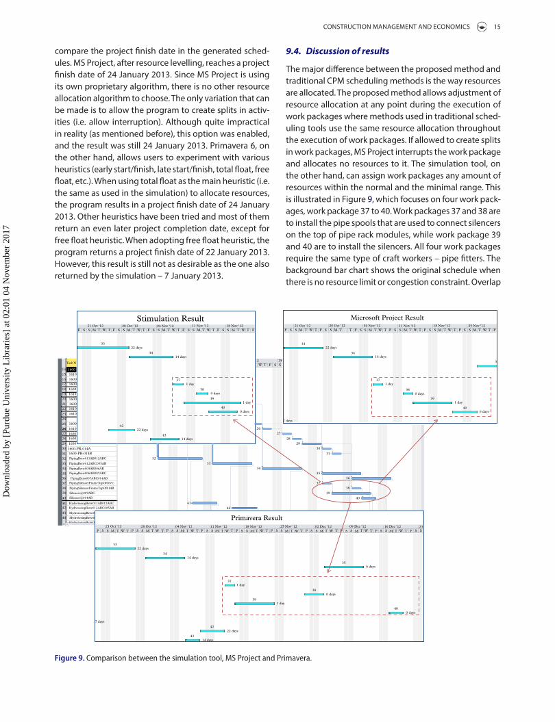
The major difference between the proposed method and traditional CPM scheduling methods is the way resources are allocated. The proposed method allows adjustment of resource allocation at any point during the execution of work packages where methods used in traditional sched-uling tools use the same resource allocation throughout the execution of work packages. If allowed to create splits in work packages, MS Project interrupts the work package and allocates no resources to it. The simulation tool, on the other hand, can assign work packages any amount of resources within the normal and the minimal range. This is illustrated in Figure 9, which focuses on four work pack-ages, work package 37 to 40. Work packages 37 and 38 are to install the pipe spools that are used to connect silencers on the top of pipe rack modules, while work package 39 and 40 are to install the silencers. All four work packages require the same type of craft workers – pipe fitters. The background bar chart shows the original schedule when there is no resource limit or congestion constraint. Overlap
compare the project finish date in the generated sched-ules. MS Project, after resource levelling, reaches a project finish date of 24 January 2013. Since MS Project is using its own proprietary algorithm, there is no other resource allocation algorithm to choose. The only variation that can be made is to allow the program to create splits in activ-ities (i.e. allow interruption). Although quite impractical in reality (as mentioned before), this option was enabled, and the result was still 24 January 2013. Primavera 6, on the other hand, allows users to experiment with various heuristics (early start/finish, late start/finish, total float, free float, etc.). When using total float as the main heuristic (i.e. the same as used in the simulation) to allocate resources, the program results in a project finish date of 24 January 2013. Other heuristics have been tried and most of them return an even later project completion date, except for free float heuristic. When adopting free float heuristic, the program returns a project finish date of 22 January 2013. However, this result is still not as desirable as the one also returned by the simulation – 7 January 2013.
HydrotesingBetw0
151617
181920
2122
2324
2526262728
2930
3132
3334
3536373839
40
4142
4344
14 16001610
Task N
1600160016001610
160016001610
1610
1600
1610
16001600
1600
1600-PR-014A
PipingBetw011AB012ABC
PipingBetw012ABC005AB
PipingBetw005AB006AB
PipingBetw006AB007ABC
PipingBetw007ABC014AB
PipingSilencerFrameTopOf007C
PipingSilencerFrameTopOf014B
Silencer@007ABC
Silencer@014AB
HydrotesingBetw011AB012ABC
HydrotesingBetw012ABC005AB
HydrotesingBetw0
HydrotesingBetw0
1600-PR-014B
F
F FS S M W W W W W W W W WT T T T T T T T T T T T T T T T T TM M M M M M MMS S S S S S S S S S S S S S S S S SF F F F F F F F
FS S S SM M T W T F S S M T W T F S S M T W T F S S M T W T FT TW21 Oct ‘12
21 Oct ‘12 28 Oct ‘12 04 Nov ‘12 11 Nov ‘12 18 Nov ‘12 25 Nov ‘12 02 Dec ‘12 09 Dec ‘12 16 Dec ‘12 23
28 Oct ‘12 04 Nov ‘12 11 Nov ‘12 18 Nov ‘12
Stimulation Result21 Oct ‘12
F S S M WT T T T T W W W WT T T T T T TM M M M MS S S S S S S S S SF F F F F F28 Oct ‘12 04 Nov ‘12 11 Nov ‘12 18 Nov ‘12 25 Nov ‘12
Microsoft Project Result
Primavera Result
3322 days
34
371 day
38
39
40
0 days
1 day
0 days
4222 days
43
32
33
34
37
391 day
38
40
35
0 days
22 days
0 days
6 days
1 day
7 days
42
43
14 days
22 days
33
42
34
35
37
39
36
38
40
2627
22 days
34
37
38
39
40
3
1 day
14 days
1 day
0 days
0 days
2829
30
31
14 days
14 days
7 days
14 days
33
2 28W T F SS
41
Figure 9. Comparison between the simulation tool, Ms Project and Primavera.
Dow
nloa
ded
by [
Purd
ue U
nive
rsity
Lib
rari
es]
at 0
2:01
04
Nov
embe
r 20
17
16 D. HU ET AL.
purpose. Congestion limit can be better implemented by measuring the total “workable” area in each work area and calculating the minimal work area requirement for each trade. Using the total available area as congestion limit might be more accurate than using the total number of workers can be present in the same area as area require-ment might vary from one trade to another.
The size of WAPs can be improved by better measure-ments. For example, for piping, it can be measured as the number of pipe spools in each work area. For steel structure, it can use total weight of steel members to be installed in each work area.
The cost associated with resource allocation has not been considered in the simulation. The schedule is improved only in terms of overall project duration but if the overall project cost is also reduced is a question to be answered. This is especially important when it is a lump sum project, but might not as important when it is a reim-bursable project and the client is willing pay the cost to obtain the shorter project duration.
Priority of work packages are calculated based on the “least total float” heuristic. The simulation should also be able to use priority values that overridden by field superinten-dents and managers and compare the results. This is advan-tage of using simulation to test multiple “what-if” scenarios.
Finally, a limitation of the proposed system is that it requires more input than a traditional CPM scheduling tool. Therefore, integration with other information sys-tems used by contractors is crucial to facilitate practical use. A standalone database is used for this study. All data are manually imported into database. Manpower levels for work packages can be linked to estimating systems and part of the precedence dependency information can be derived automatically from 3D models based on the physical constraints. Detailed comparison between the proposed method and location based scheduling meth-ods can also be pursued in future work to investigate dif-ferences and similarities, and the potential of integration between the two methods.
11. Conclusions
This paper presents a time-stepped simulation-based scheduling method that dissects work packages into smaller time unit based (daily/weekly/monthly) segments. It simulates the execution of work packages for each time step and allows for variable resource allocation to these work packages if either the resource limit or the conges-tion limit is reached. Both resource availability levels and utilization levels can be variable during the course of work packages. Work packages can also be performed/started in an understaffed scenario and do not always require the full crew size. It also accounts for all traditional constraints
between these work packages leads to a situation where a higher-priority work package starts during the execu-tion of a lower-priority work package. For example, work package 38 and 40 both have overlap with work package 39. The resource limit for pipe fitters is 20 and each work package normally requires a crew of 10 pipe fitters. During the overlap, the total resource requirement could surge to 20, which exceeds the congestion limit of 16. Figure 9 also shows the total float of each work package (i.e. the number of days on the right of the bars), e.g. work package 37 and 39 have 1 day total float, while work packages 38 and 40 have zero total float, and thus, have higher priority than the former two work packages. Although work package 39 starts before work packages 38 and 40, resource is re-allo-cated when work package 38 and 40 start.
MS Project and P6 assign either the full amount of required resources or nothing to work packages. Therefore, if the aforementioned situation occurs, it completely post-pones one work package or the other. Figure 9 shows that MS Project and P6 can only perform one work package at a time, though the sequence might be different. However, the proposed method allows these work packages to be performed concurrently. When work package 38 starts, it can use some resources redirected from work package 39, even though 39 is still in progress. The two-round resource allocation algorithm allocates 8 pipe fitters to work pack-age 39 in the first round. In the second round of resource allocation, it allocates the remaining 8 pipe fitters to work package 38 since it has higher priority. In this way, the con-tinuity of work package 39 is maintained and work pack-age 38 can be started immediately without delay. The same process happens when work package 40 starts. In the case of the proposed method, all four work packages can be completed within 10 working days (i.e. from 7 November to 20 November 2012). The duration of work package 39 is also changed from 6 days to 7.5 days. In contrast, it takes 15 working days and 26 working days to complete these work packages in MS Project and P6, respectively.
10. Limitations and future work
There are a number of limitations of the proposed system that need to be addressed in future work. First, Congestion in this paper is restricted to the number of workers to work at the same work area at the same time. Other factors that contribute to congestions such as conflicts between product space, storage areas, equipment spaces and paths are not addressed in a direct way in this work but can be modelled indirectly by reducing the maximum number of workers allowed in a certain work area based on usage and available space in that area. A 2D/3D model could be of help to implement congestion limits but it is not a must-have. A project plot plan would be sufficient for this
Dow
nloa
ded
by [
Purd
ue U
nive
rsity
Lib
rari
es]
at 0
2:01
04
Nov
embe
r 20
17

CONSTRUCTION MANAGEMENT AND ECONOMICS 17
Al-Hussein, M., Alkass, S. and Moselhi, O., 2005. Optimization Algorithm for Selection and on Site Location of Mobile Cranes. Journal of construction engineering and management, 131 (5), 579–590.
Balci, O., 1998 Verification, validation, and accreditation In: D.J. Medeiros, E.F. Watson, J.S. Carson, and M.S. Manivannan, eds. Proceedings of the 1998 winter simulation conference. Los Alamitos, CA: IEEE, Vol. 1, 41–48.
Banks, J., 1998. Handbook of simulation: principles, methodology, advances, applications, and practice. Wiley.
Beliveau, Y.J. and Thabet, W.Y., 1994. Modeling work space to schedule repetitive floors in multistory buildings. Journal of construction engineering and management, 120 (1), 96–116.
Castro, P.M., et al., 2014. Optimal maintenance scheduling of a gas engine power plant using generalized disjunctive programming. AIChE journal, 60 (6), 2083–2097.
Chan, W., Chua, D.K.H. and Kannan, G., 1996. Construction resource scheduling with genetic algorithms. Journal of Construction Engineering and Management, 122 (2), 125–132.
Christodoulou, S., 2010. Scheduling resource-constrained projects with ant colony optimization artificial agents. Journal of computing in civil engineering, 24 (1), 45–55.
Construction Industry Institute, 2011. Enhanced work packaging: design through workface execution. Implementation resource, 272.
Davis, E.W. and Patterson, J.H., 1975. A comparison of heuristic and optimum solutions in resource-constrained project scheduling. Management science, 21 (8), 944–955.
Demeulemeester, E.L. 2002, Project scheduling: a research handbook. Boston: Kluwer Academic.
Elbeltagi, E., Hegazy, T. and Grierson, D., 2005. Comparison among five evolutionary-based optimization algorithms. Advanced engineering informatics, 19 (1), 43–53.
Haas, C.T., et al., (2000). Prefabrication and preassembly trends and effects on the construction workforce. Austin, TX: Center for Construction Industry Studies, Report No. 14
Hartmann, Sonke, 2013. Project scheduling with resource capacities and requests varying with time: a case study. Flexible services and manufacturing journal, 25 (1–2), 74–93.
Hegazy, T., 1999. Optimization of resource allocation and leveling using genetic algorithms. Journal of construction engineering and management, 125 (3), 167–175.
Hegazy, T. and Menesi, W., 2010. Critical path segments scheduling technique. Journal of Construction Engineering and Management, 136 (10), 1078–1085.
Horner, R.M.W., 1995. Effects of accelerated working, delays and disruption on labour productivity. Ascot: Chartered Institute of Building.
Hu, D. and Mohamed, Y., 2010 State-Based Simulation Mechanism for Facilitating Project Schedule Updating. In: Construction Research Congress 2010, pp. 369–378.
Jiang, G. and Shi, J., 2005. Exact algorithm for solving project scheduling problems under multiple resource constraints. Journal of construction engineering and management, 131 (9), 986–992.
Thomas, Jr., H.R. and Smith, G.R. 1990, Loss of construction labor productivity due to inefficiencies and disruptions: the weight of expert opinion. Pennsylvania State University, PTI Report No 9019 Pennsylvania Transportation Institute.
Kandil, A. and El-Rayes, K., 2006. MACROS: multiobjective automated construction resource optimization system. Journal of management in engineering, 22 (3), 126–134.
of work packages such as precedence relationships, calen-dars and hard time constraints. A real industrial construc-tion case was used to test the practicality of the method. The advantage of using simulation for scheduling is the capability of handling a large number of activities and work packages at high level of granularity and the ability to quantify the impact of resource allocation and conges-tion limits decisions. The schedules generated from the proposed method were compared with those produced by popular CPM-based project scheduling tools. The pro-posed framework returns shorter overall project duration compared to two other scheduling tools as it has more flexible resource allocation mechanism which allows for work packages to be carried out concurrently. This flexi-bility is frequently utilized in real-life construction practice but rarely addressed by prior scheduling research. Another advantage of the proposed framework is that it can take as-built data and run simulation from current time of the project instead of having to start over from the very begin-ning. The simulation allows for experimenting with various priority scenarios for work packages.
Disclosure statement
No potential conflict of interest was reported by the authors.
Funding
This work was supported by the Natural Science and Engineer-ing Research Council of Canada (NSERC) and PCL Industrial Management Inc. through the Collaborative Research and De-velopment (CRD) [grant number CRDPJ 416362 – 11].
ORCID
Yasser Mohamed http://orcid.org/0000-0001-9170-9557
References
Alberta Economic Development Authority, 2004. Mega project excellence: preparing for Alberta’s legacy - an action plan. Available from: https://aeda.alberta.ca/AEDA%20Public%20Document%20Library/MegaProjectExcel_Dec102004.pdf [Accessed 16 January 2013].
AbouRizk, S. and Mohamed, Y., 2000. Simphony-an integrated environment for construction simulation. In: 2000 Winter simulation conference proceedings, 2, 1914.
AbouRizk, S.M., Dozzi, S.P., and Sawhney, A., 1993. An automated database system for construction bidding. In: Proceedings of the 5th international conference on computing in civil and building engineering - V-ICCCBE, Jun 7–9 1993 New York, NY. Anaheim, CA: ASCE, 678.
Akinci, B., Fischer, M., and Kunz, J., 2002. Automated generation of work spaces required by construction activities. Journal of construction engineering and management, 128 (4), 306–315.
Dow
nloa
ded
by [
Purd
ue U
nive
rsity
Lib
rari
es]
at 0
2:01
04
Nov
embe
r 20
17

18 D. HU ET AL.
Ovararin, Nuntapong and Popescu, Calin M., 2001. Field factors affecting masonry productivity. AACE international transactions, ES91.
Riley, D.R. and Sanvido, V.E., 1997. Space planning method for multistory building construction. Journal of construction engineering and management, 123 (2), 171–180.
Robinson, S., 2004. Simulation – the practice of model development and use. Wiley.
Ryan, G., 2009. Schedule for sale: workface planning for construction projects. Bloomington, IN: AuthorHouse.
Sargent, R.G., 2013. Verification and validation of simulation models. Journal of simulation, 7 (1), 12–24.
Senior, B.A. and Halpin, D.W., 1998. Simplified simulation system for construction projects. Journal of construction engineering and management, 124 (1), 72–81.
Song, L. and AbouRizk, S.M., 2006. Virtual shop model for experimental planning of steel fabrication projects. Journal of computing in civil engineering, 20 (5), 308–316.
Taghaddos, H., et al., 2012. Simulation-based auction protocol for resource scheduling problems. Journal of construction engineering and management, 138 (1), 31–42.
Thabet, W.Y. and Beliveau, Y.J., 1994. Modeling work space to schedule repetitive floors in multistory buildings. Journal of construction engineering and management, 120 (1), 96–116.
Tommelein, I.D. and Zouein, P.P., 2001. Improvement algorithm for limited space scheduling. Journal of construction engineering and management, 127 (2), 116–124.
Wang, P., (2006). Production-based large scale construction simulation modeling. Thesis (PhD). University of Alberta, Edmonton.
Williams, G.V., 1995. Fast track pros and cons: considerations for industrial projects. Journal of management in engineering, 11 (5), 24–32.
Wyss, S., 2009. Active management of pipe spool fabricators. Chemical engineering, 116 (1), 40–45.
Zhang, H., Tam, C.M., and Shi, J.J., 2002. Simulation-based methodology for project scheduling. Construction management and economics, 20 (8), 667–678.
Zouein, P.P. and Tommelein, I.D., 2001. Improvement algorithm for limited space scheduling. Journal of construction engineering and management, 127 (2), 116–124.
Karshenas, S. and Haber, D., 1990. Economic optimization of construction project scheduling. Construction management and economics, 8 (2), 135–146.
Kim, K. and de la Garza, Jesús M., 2005. Evaluation of the resource-constrained critical path method algorithms. Journal of construction engineering and management, 131 (5), 522–532.
Kolisch, R., 1996. Efficient priority rules for the resource-constrained project scheduling problem. Journal of operations management, 14 (3), 179–192.
Lowe, R. et al., (2012). A comparison of location-based scheduling with the traditional critical path method. Paper prepared for the American college of construction lawyers 2012 annual meeting, San Francisco, CA. Available from: http://goo.gl/5aFLT [Accessed 8 June 2017].
Lu, M. and Li, H., 2003. Resource-activity critical-path method for construction planning. Journal of construction engineering and management, 129 (4), 412–420.
Lu, M., Lam, H., and Dai, F., 2008. Resource-constrained critical path analysis based on discrete event simulation and particle swarm optimization. Automation in construction, 17 (6), 670–681.
Mallasi, Z., 2006. Dynamic quantification and analysis of the construction workspace congestion utilising 4D visualisation. Automation in Construction, 15 (5), 640–655.
Martinez, J., Ioannou, P.G., and Carr, R.I., 1994, State and resource based construction process simulation. In: Proceedings of the 1st congress on computing in civil engineering. part 1 (of 2), Jun 20–22 1994 New York, NY. Washington, DC, ASCE, 177.
Marzouk, M. and Moselhi, O., 2004. Multiobjective optimization of earthmoving operations. Journal of construction engineering and management, 130 (1), 105–113.
Mohamed, Y., et al., 2007. Simulation‐based scheduling of module assembly yards: case study. Engineering, construction and architectural management, 14 (3), 293–311.
Moselhi, O. and Lorterapong, P., 1993. Near optimal solution for resource-constrained scheduling problems. Construction management and economics, 11 (4), 293–303.
Nandakumar, V. and Ahuja, H.N., 1985. Simulation model to forecast project completion time. Journal of construction engineering and management, 111 (4), 325–342.
Ng, S.T. and Zhang, Y., 2008. Optimizing construction time and cost using ant colony optimization approach. Journal of construction engineering and management, 134 (9), 721–728.
Dow
nloa
ded
by [
Purd
ue U
nive
rsity
Lib
rari
es]
at 0
2:01
04
Nov
embe
r 20
17
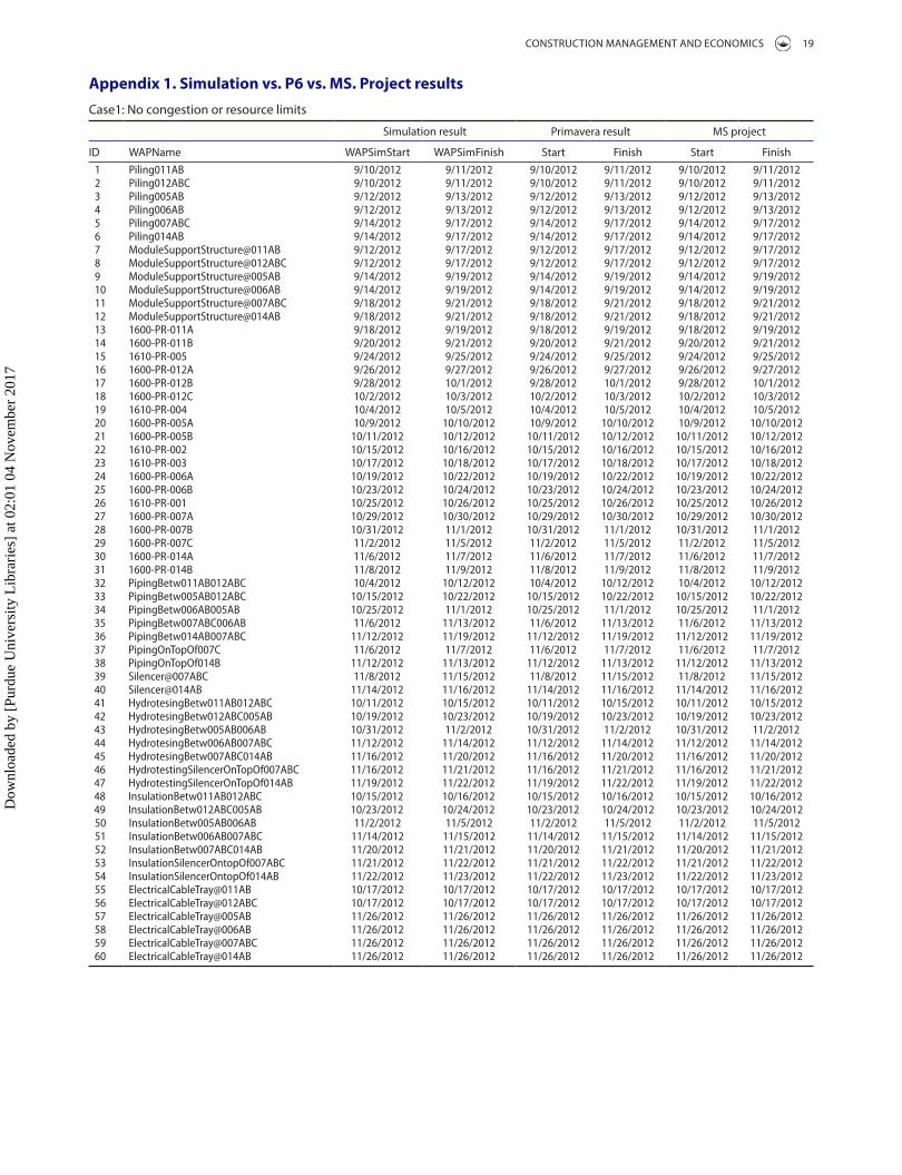
CONSTRUCTION MANAGEMENT AND ECONOMICS 19
Appendix 1. Simulation vs. P6 vs. MS. Project resultsCase1: No congestion or resource limits
Simulation result Primavera result MS project
ID WAPName WAPSimStart WAPSimFinish Start Finish Start Finish1 Piling011aB 9/10/2012 9/11/2012 9/10/2012 9/11/2012 9/10/2012 9/11/20122 Piling012aBC 9/10/2012 9/11/2012 9/10/2012 9/11/2012 9/10/2012 9/11/20123 Piling005aB 9/12/2012 9/13/2012 9/12/2012 9/13/2012 9/12/2012 9/13/20124 Piling006aB 9/12/2012 9/13/2012 9/12/2012 9/13/2012 9/12/2012 9/13/20125 Piling007aBC 9/14/2012 9/17/2012 9/14/2012 9/17/2012 9/14/2012 9/17/20126 Piling014aB 9/14/2012 9/17/2012 9/14/2012 9/17/2012 9/14/2012 9/17/20127 Modulesupportstructure@011aB 9/12/2012 9/17/2012 9/12/2012 9/17/2012 9/12/2012 9/17/20128 Modulesupportstructure@012aBC 9/12/2012 9/17/2012 9/12/2012 9/17/2012 9/12/2012 9/17/20129 Modulesupportstructure@005aB 9/14/2012 9/19/2012 9/14/2012 9/19/2012 9/14/2012 9/19/201210 Modulesupportstructure@006aB 9/14/2012 9/19/2012 9/14/2012 9/19/2012 9/14/2012 9/19/201211 Modulesupportstructure@007aBC 9/18/2012 9/21/2012 9/18/2012 9/21/2012 9/18/2012 9/21/201212 Modulesupportstructure@014aB 9/18/2012 9/21/2012 9/18/2012 9/21/2012 9/18/2012 9/21/201213 1600-Pr-011a 9/18/2012 9/19/2012 9/18/2012 9/19/2012 9/18/2012 9/19/201214 1600-Pr-011B 9/20/2012 9/21/2012 9/20/2012 9/21/2012 9/20/2012 9/21/201215 1610-Pr-005 9/24/2012 9/25/2012 9/24/2012 9/25/2012 9/24/2012 9/25/201216 1600-Pr-012a 9/26/2012 9/27/2012 9/26/2012 9/27/2012 9/26/2012 9/27/201217 1600-Pr-012B 9/28/2012 10/1/2012 9/28/2012 10/1/2012 9/28/2012 10/1/201218 1600-Pr-012C 10/2/2012 10/3/2012 10/2/2012 10/3/2012 10/2/2012 10/3/201219 1610-Pr-004 10/4/2012 10/5/2012 10/4/2012 10/5/2012 10/4/2012 10/5/201220 1600-Pr-005a 10/9/2012 10/10/2012 10/9/2012 10/10/2012 10/9/2012 10/10/201221 1600-Pr-005B 10/11/2012 10/12/2012 10/11/2012 10/12/2012 10/11/2012 10/12/201222 1610-Pr-002 10/15/2012 10/16/2012 10/15/2012 10/16/2012 10/15/2012 10/16/201223 1610-Pr-003 10/17/2012 10/18/2012 10/17/2012 10/18/2012 10/17/2012 10/18/201224 1600-Pr-006a 10/19/2012 10/22/2012 10/19/2012 10/22/2012 10/19/2012 10/22/201225 1600-Pr-006B 10/23/2012 10/24/2012 10/23/2012 10/24/2012 10/23/2012 10/24/201226 1610-Pr-001 10/25/2012 10/26/2012 10/25/2012 10/26/2012 10/25/2012 10/26/201227 1600-Pr-007a 10/29/2012 10/30/2012 10/29/2012 10/30/2012 10/29/2012 10/30/201228 1600-Pr-007B 10/31/2012 11/1/2012 10/31/2012 11/1/2012 10/31/2012 11/1/201229 1600-Pr-007C 11/2/2012 11/5/2012 11/2/2012 11/5/2012 11/2/2012 11/5/201230 1600-Pr-014a 11/6/2012 11/7/2012 11/6/2012 11/7/2012 11/6/2012 11/7/201231 1600-Pr-014B 11/8/2012 11/9/2012 11/8/2012 11/9/2012 11/8/2012 11/9/201232 PipingBetw011aB012aBC 10/4/2012 10/12/2012 10/4/2012 10/12/2012 10/4/2012 10/12/201233 PipingBetw005aB012aBC 10/15/2012 10/22/2012 10/15/2012 10/22/2012 10/15/2012 10/22/201234 PipingBetw006aB005aB 10/25/2012 11/1/2012 10/25/2012 11/1/2012 10/25/2012 11/1/201235 PipingBetw007aBC006aB 11/6/2012 11/13/2012 11/6/2012 11/13/2012 11/6/2012 11/13/201236 PipingBetw014aB007aBC 11/12/2012 11/19/2012 11/12/2012 11/19/2012 11/12/2012 11/19/201237 Pipingontopof007C 11/6/2012 11/7/2012 11/6/2012 11/7/2012 11/6/2012 11/7/201238 Pipingontopof014B 11/12/2012 11/13/2012 11/12/2012 11/13/2012 11/12/2012 11/13/201239 silencer@007aBC 11/8/2012 11/15/2012 11/8/2012 11/15/2012 11/8/2012 11/15/201240 silencer@014aB 11/14/2012 11/16/2012 11/14/2012 11/16/2012 11/14/2012 11/16/201241 HydrotesingBetw011aB012aBC 10/11/2012 10/15/2012 10/11/2012 10/15/2012 10/11/2012 10/15/201242 HydrotesingBetw012aBC005aB 10/19/2012 10/23/2012 10/19/2012 10/23/2012 10/19/2012 10/23/201243 HydrotesingBetw005aB006aB 10/31/2012 11/2/2012 10/31/2012 11/2/2012 10/31/2012 11/2/201244 HydrotesingBetw006aB007aBC 11/12/2012 11/14/2012 11/12/2012 11/14/2012 11/12/2012 11/14/201245 HydrotesingBetw007aBC014aB 11/16/2012 11/20/2012 11/16/2012 11/20/2012 11/16/2012 11/20/201246 Hydrotestingsilencerontopof007aBC 11/16/2012 11/21/2012 11/16/2012 11/21/2012 11/16/2012 11/21/201247 Hydrotestingsilencerontopof014aB 11/19/2012 11/22/2012 11/19/2012 11/22/2012 11/19/2012 11/22/201248 insulationBetw011aB012aBC 10/15/2012 10/16/2012 10/15/2012 10/16/2012 10/15/2012 10/16/201249 insulationBetw012aBC005aB 10/23/2012 10/24/2012 10/23/2012 10/24/2012 10/23/2012 10/24/201250 insulationBetw005aB006aB 11/2/2012 11/5/2012 11/2/2012 11/5/2012 11/2/2012 11/5/201251 insulationBetw006aB007aBC 11/14/2012 11/15/2012 11/14/2012 11/15/2012 11/14/2012 11/15/201252 insulationBetw007aBC014aB 11/20/2012 11/21/2012 11/20/2012 11/21/2012 11/20/2012 11/21/201253 insulationsilencerontopof007aBC 11/21/2012 11/22/2012 11/21/2012 11/22/2012 11/21/2012 11/22/201254 insulationsilencerontopof014aB 11/22/2012 11/23/2012 11/22/2012 11/23/2012 11/22/2012 11/23/201255 electricalCabletray@011aB 10/17/2012 10/17/2012 10/17/2012 10/17/2012 10/17/2012 10/17/201256 electricalCabletray@012aBC 10/17/2012 10/17/2012 10/17/2012 10/17/2012 10/17/2012 10/17/201257 electricalCabletray@005aB 11/26/2012 11/26/2012 11/26/2012 11/26/2012 11/26/2012 11/26/201258 electricalCabletray@006aB 11/26/2012 11/26/2012 11/26/2012 11/26/2012 11/26/2012 11/26/201259 electricalCabletray@007aBC 11/26/2012 11/26/2012 11/26/2012 11/26/2012 11/26/2012 11/26/201260 electricalCabletray@014aB 11/26/2012 11/26/2012 11/26/2012 11/26/2012 11/26/2012 11/26/2012
Dow
nloa
ded
by [
Purd
ue U
nive
rsity
Lib
rari
es]
at 0
2:01
04
Nov
embe
r 20
17

20 D. HU ET AL.
Case2: With congestion and resource limits
Simulation Result Primavera Result MS Project
ID WAPName WAPSimStart WAPSimFinish Start Finish Start Finish1 Piling011aB 9/10/2012 9/11/2012 9/10/2012 9/11/2012 9/10/2012 9/11/20122 Piling012aBC 9/10/2012 9/11/2012 9/10/2012 9/11/2012 9/10/2012 9/11/20123 Piling005aB 9/12/2012 9/13/2012 9/12/2012 9/13/2012 9/12/2012 9/13/20124 Piling006aB 9/12/2012 9/13/2012 9/12/2012 9/13/2012 9/12/2012 9/13/20125 Piling007aBC 9/14/2012 9/17/2012 9/14/2012 9/17/2012 9/14/2012 9/17/20126 Piling014aB 9/14/2012 9/17/2012 9/14/2012 9/17/2012 9/14/2012 9/17/20127 Modulesupportstructure@011aB 9/12/2012 9/17/2012 9/12/2012 9/17/2012 9/12/2012 9/17/20128 Modulesupportstructure@012aBC 9/12/2012 9/17/2012 9/12/2012 9/17/2012 9/12/2012 9/17/20129 Modulesupportstructure@005aB 9/18/2012 9/21/2012 9/18/2012 9/21/2012 9/18/2012 9/21/201210 Modulesupportstructure@006aB 9/24/2012 9/27/2012 9/24/2012 9/27/2012 9/24/2012 9/27/201211 Modulesupportstructure@007aBC 9/28/2012 10/3/2012 9/28/2012 10/3/2012 9/28/2012 10/3/201212 Modulesupportstructure@014aB 10/4/2012 10/10/2012 10/4/2012 10/10/2012 10/4/2012 10/10/201213 1600-Pr-011a 9/18/2012 9/19/2012 9/18/2012 9/19/2012 9/18/2012 9/19/201214 1600-Pr-011B 9/20/2012 9/21/2012 9/20/2012 9/21/2012 9/20/2012 9/21/201215 1610-Pr-005 9/24/2012 9/25/2012 9/24/2012 9/25/2012 9/24/2012 9/25/201216 1600-Pr-012a 9/26/2012 9/27/2012 9/26/2012 9/27/2012 9/26/2012 9/27/201217 1600-Pr-012B 9/28/2012 10/1/2012 9/28/2012 10/1/2012 9/28/2012 10/1/201218 1600-Pr-012C 10/2/2012 10/3/2012 10/2/2012 10/3/2012 10/2/2012 10/3/201219 1610-Pr-004 10/4/2012 10/5/2012 10/4/2012 10/5/2012 10/4/2012 10/5/201220 1600-Pr-005a 10/9/2012 10/10/2012 10/9/2012 10/10/2012 10/9/2012 10/10/201221 1600-Pr-005B 10/11/2012 10/12/2012 10/11/2012 10/12/2012 10/11/2012 10/12/201222 1610-Pr-002 10/15/2012 10/16/2012 10/15/2012 10/16/2012 10/15/2012 10/16/201223 1610-Pr-003 10/17/2012 10/18/2012 10/17/2012 10/18/2012 10/17/2012 10/18/201224 1600-Pr-006a 10/19/2012 10/22/2012 10/19/2012 10/22/2012 10/19/2012 10/22/201225 1600-Pr-006B 10/23/2012 10/24/2012 10/23/2012 10/24/2012 10/23/2012 10/24/201226 1610-Pr-001 10/25/2012 10/26/2012 10/25/2012 10/26/2012 10/25/2012 10/26/201227 1600-Pr-007a 10/29/2012 10/30/2012 10/29/2012 10/30/2012 10/29/2012 10/30/201228 1600-Pr-007B 10/31/2012 11/1/2012 10/31/2012 11/1/2012 10/31/2012 11/1/201229 1600-Pr-007C 11/2/2012 11/5/2012 11/2/2012 11/5/2012 11/2/2012 11/5/201230 1600-Pr-014a 11/6/2012 11/7/2012 11/6/2012 11/7/2012 11/6/2012 11/7/201231 1600-Pr-014B 11/8/2012 11/9/2012 11/8/2012 11/9/2012 11/8/2012 11/9/201232 PipingBetw011aB012aBC 10/4/2012 10/15/2012 10/4/2012 10/12/2012 10/4/2012 10/12/201233 PipingBetw005aB012aBC 10/19/2012 10/29/2012 10/19/2012 10/26/2012 10/19/2012 10/26/201234 PipingBetw006aB005aB 10/29/2012 11/7/2012 10/29/2012 11/5/2012 10/29/2012 11/5/201235 PipingBetw007aBC006aB 12/12/2012 12/20/2012 12/4/2012 12/12/2012 11/27/2012 12/4/201236 PipingBetw014aB007aBC 11/29/2012 12/7/2012 1/8/2013 1/16/2013 12/5/2012 12/12/201237 Pipingontopof007C 11/7/2012 11/9/2012 11/14/2012 11/15/2012 11/6/2012 11/7/201238 Pipingontopof014B 11/12/2012 11/14/2012 11/30/2012 12/4/2012 11/12/2012 11/13/201239 silencer@007aBC 11/9/2012 11/20/2012 11/16/2012 11/26/2012 11/14/2012 11/21/201240 silencer@014aB 11/14/2012 11/20/2012 12/17/2012 12/20/2012 11/22/2012 11/26/201241 HydrotesingBetw011aB012aBC 10/11/2012 10/16/2012 10/15/2012 10/17/2012 10/15/2012 10/17/201242 HydrotesingBetw012aBC005aB 10/25/2012 10/30/2012 11/9/2012 11/13/2012 12/13/2012 12/17/201243 HydrotesingBetw005aB006aB 11/2/2012 11/8/2012 11/6/2012 11/8/2012 12/18/2012 12/20/201244 HydrotesingBetw006aB007aBC 12/18/2012 1/2/2013 12/12/2012 12/17/2012 12/21/2012 1/3/201345 HydrotesingBetw007aBC014aB 12/5/2012 12/11/2012 1/16/2013 1/21/2013 1/10/2013 1/14/201346 Hydrotestingsilencerontopof007aBC 11/23/2012 11/30/2012 11/26/2012 11/30/2012 1/4/2013 1/9/201347 Hydrotestingsilencerontopof014aB 11/20/2012 11/26/2012 12/20/2012 1/4/2013 1/15/2013 1/18/201348 insulationBetw011aB012aBC 10/15/2012 10/17/2012 10/18/2012 10/19/2012 10/18/2012 10/19/201249 insulationBetw012aBC005aB 10/29/2012 11/1/2012 11/14/2012 11/15/2012 12/18/2012 12/19/201250 insulationBetw005aB006aB 11/7/2012 11/9/2012 11/9/2012 11/12/2012 12/21/2012 1/2/201351 insulationBetw006aB007aBC 12/21/2012 1/3/2013 12/17/2012 12/19/2012 1/4/2013 1/7/201352 insulationBetw007aBC014aB 12/10/2012 12/12/2012 1/21/2013 1/23/2013 1/15/2013 1/16/201353 insulationsilencerontopof007aBC 11/29/2012 12/3/2012 11/30/2012 12/4/2012 1/17/2013 1/18/201354 insulationsilencerontopof014aB 11/23/2012 11/27/2012 1/4/2013 1/8/2013 1/21/2013 1/22/201355 electricalCabletray@011aB 10/18/2012 10/18/2012 10/22/2012 10/22/2012 10/22/2012 10/22/201256 electricalCabletray@012aBC 10/18/2012 10/18/2012 10/22/2012 10/22/2012 10/22/2012 10/22/201257 electricalCabletray@005aB 1/3/2013 1/4/2013 1/23/2013 1/24/2013 1/23/2013 1/23/201358 electricalCabletray@006aB 1/3/2013 1/4/2013 1/23/2013 1/24/2013 1/23/2013 1/23/201359 electricalCabletray@007aBC 1/4/2013 1/7/2013 1/24/2013 1/25/2013 1/24/2013 1/24/201360 electricalCabletray@014aB 1/4/2013 1/7/2013 1/24/2013 1/25/2013 1/24/2013 1/24/2013
Dow
nloa
ded
by [
Purd
ue U
nive
rsity
Lib
rari
es]
at 0
2:01
04
Nov
embe
r 20
17