A Simple Method for Robust Vehicular Communication with ... · A Simple Method for Robust Vehicular...
5
A Simple Method for Robust Vehicular Communication with Multiple Nonideal Antennas Keerthi Kumar Nagalapur, Erik G. Str¨ om, Fredrik Br¨ annstr¨ om, Jan Carlsson, and Kristian Karlsson Abstract—For critical vehicular communication services, such as traffic safety and traffic efficiency, it is advisable to design systems with robustness as the main criteria, possibly at the price of reduced peak performance and efficiency. We describe a simple, low-cost method for combining the output of L nonideal (i.e., nonisotropic) antennas to the input signal to a single- port receiver with the aim to guarantee robustness, i.e., to minimize the probability that K consecutive packets arriving from the worst-case angle-of-arrival are decoded incorrectly. To minimize complexity, the combining network does not estimate or use channel state information (complex channel gains, noise levels, etc.). The combining network consists of L - 1 analog phase shifters whose phases are affine functions of time. For a general L and the case when the packet error probability decays exponentially with the received SNR, the optimum slopes of the affine functions can be computed by solving an optimization problem that depends on the antenna far field functions. We provide an analytical solution for the special case of L =2 antennas, which turns out to be independent of the antenna patterns. In an experimental setup consisting of two monopole antennas mounted on the roof of a Volvo XC90, the proposed combining method is shown to give significant performance gains compared to using just one of the antennas. I. I NTRODUCTION Vehicular traffic safety and traffic efficiency applications demand robust (reliable) communication between vehicles. Many of these applications rely on that vehicles transmits periodic status messages containing current position, speed, heading, etc. These packets are referred to as cooperative awareness messages (CAMs) in Europe and basic safety mes- sages (BSMs) in the US [1], [2]. The time between packets, T , is typically in the order of 100 ms, but can vary due to vehicle dynamics and application requirements. Occasional packet losses are normally not problematic, since the CAMs contain information of physical quantities that vary slowly over the time duration of a few packets. However, if a number of consecutive packets from a vehicle are lost, this might lead to an application failure. It is therefore reasonable to design the communication system to minimize the burst error probability Keerthi Kumar Nagalapur, Fredrik Br¨ annstr¨ om, and Erik G. Str¨ om are with the Communication Systems Group, Dept. of Electrical Engineering, Chalmers University of Technology, SE-412 96, Gothenburg, Sweden, E-mail: {keerthi, fredrik.brannstrom, erik.strom}@chalmers.se. Jan Carlsson is with Provinn AB and Dept. of Electrical Engineering, Chalmers University of Technology, Gothenburg, Sweden, E-mail: [email protected]. Kristian Karlsson is with the Dept. of Safety and Transport at RISE Research Institutes of Sweden, Bor˚ as, Sweden, E-mail: [email protected]. This research has been carried out in ChaseOn in a project financed by Vinnova, Chalmers, Bluetest, Ericsson, Keysight, RISE, Smarteq, and Volvo Cars. (BrEP), i.e., the probability of losing K > 1 consecutive packets, where K depends on the application and T . This is in contrast to the more common design goal to minimize the packet error probability (PEP). A shark fin antenna module located on top of a vehicle’s roof is the standard method for housing the antennas used for vehicular communications today. However, conformal/hidden antennas are also being considered for the reasons of safety of the antennas, exterior appearance of the vehicle, and aero- dynamics. Radiation patterns of hidden antennas are typically far from isotropic due to the vehicle components that closely surround them. In fact, the antenna patterns might have very low, or even zero gain in certain directions, and packets arriving from an unfavorable angle of arrival (AOA) might be lost due to poor signal-to-noise ratio (SNR). Moreover, since the vehicle positions varies slowly over the time duration of a few consecutive packets, we can expect the AOA of the signal from a certain vehicle to remain approximately the same over this duration, and there is a risk of losing a number of consecutive packets from the same vehicle. The problems due to nonideal antenna patterns can be remedied by using multiple antennas with complementing radiation patterns. Combining the outputs of the multiple antennas is a well studied topic and methods such as selection combining (SC), equal gain combining (EGC), and maximal ratio combining (MRC) have been investigated thoroughly [3]. These methods either require the knowledge of the instan- taneous channel amplitude and phase, or the SNR of the output signal on each antenna. Schemes that do not require the aforementioned information for combining have also been studied. A scheme called random beamforming has been explored in [4], where the antenna pattern is randomized over several time-frequency blocks to achieve omnidirectional coverage on average. Typically, the combining methods described above require a multiport receiver (RX) to combine the signals digitally. An alternative to this approach is to use an analog combining network (ACN) consisting of analog phase shifters, variable gain amplifiers, and combiners to obtain a single combined signal that requires only a single-port RX [5], [6]. When the antennas and the RX are co-located, it is convenient to use a closed loop system where the information from the RX is used to control the analog combining network. However, from a modularity and implementation complexity point of view, it would be beneficial to devise an ACN that does not require RX feedback or knowledge of the SNR or other channel state
Transcript of A Simple Method for Robust Vehicular Communication with ... · A Simple Method for Robust Vehicular...
A Simple Method for Robust VehicularCommunication with Multiple Nonideal Antennas
Keerthi Kumar Nagalapur, Erik G. Strom, Fredrik Brannstrom, Jan Carlsson, and Kristian Karlsson
Abstract—For critical vehicular communication services, suchas traffic safety and traffic efficiency, it is advisable to designsystems with robustness as the main criteria, possibly at theprice of reduced peak performance and efficiency. We describe asimple, low-cost method for combining the output of L nonideal(i.e., nonisotropic) antennas to the input signal to a single-port receiver with the aim to guarantee robustness, i.e., tominimize the probability that K consecutive packets arrivingfrom the worst-case angle-of-arrival are decoded incorrectly. Tominimize complexity, the combining network does not estimateor use channel state information (complex channel gains, noiselevels, etc.). The combining network consists of L − 1 analogphase shifters whose phases are affine functions of time. For ageneral L and the case when the packet error probability decaysexponentially with the received SNR, the optimum slopes of theaffine functions can be computed by solving an optimizationproblem that depends on the antenna far field functions. Weprovide an analytical solution for the special case of L = 2antennas, which turns out to be independent of the antennapatterns. In an experimental setup consisting of two monopoleantennas mounted on the roof of a Volvo XC90, the proposedcombining method is shown to give significant performance gainscompared to using just one of the antennas.
I. INTRODUCTION
Vehicular traffic safety and traffic efficiency applicationsdemand robust (reliable) communication between vehicles.Many of these applications rely on that vehicles transmitsperiodic status messages containing current position, speed,heading, etc. These packets are referred to as cooperativeawareness messages (CAMs) in Europe and basic safety mes-sages (BSMs) in the US [1], [2]. The time between packets,T , is typically in the order of 100 ms, but can vary dueto vehicle dynamics and application requirements. Occasionalpacket losses are normally not problematic, since the CAMscontain information of physical quantities that vary slowly overthe time duration of a few packets. However, if a number ofconsecutive packets from a vehicle are lost, this might lead toan application failure. It is therefore reasonable to design thecommunication system to minimize the burst error probability
Keerthi Kumar Nagalapur, Fredrik Brannstrom, and Erik G. Strom are withthe Communication Systems Group, Dept. of Electrical Engineering, ChalmersUniversity of Technology, SE-412 96, Gothenburg, Sweden, E-mail: keerthi,fredrik.brannstrom, [email protected]. Jan Carlsson is with ProvinnAB and Dept. of Electrical Engineering, Chalmers University of Technology,Gothenburg, Sweden, E-mail: [email protected]. Kristian Karlsson iswith the Dept. of Safety and Transport at RISE Research Institutes of Sweden,Boras, Sweden, E-mail: [email protected].
This research has been carried out in ChaseOn in a project financed byVinnova, Chalmers, Bluetest, Ericsson, Keysight, RISE, Smarteq, and VolvoCars.
(BrEP), i.e., the probability of losing K > 1 consecutivepackets, where K depends on the application and T . This isin contrast to the more common design goal to minimize thepacket error probability (PEP).
A shark fin antenna module located on top of a vehicle’sroof is the standard method for housing the antennas used forvehicular communications today. However, conformal/hiddenantennas are also being considered for the reasons of safetyof the antennas, exterior appearance of the vehicle, and aero-dynamics. Radiation patterns of hidden antennas are typicallyfar from isotropic due to the vehicle components that closelysurround them. In fact, the antenna patterns might have verylow, or even zero gain in certain directions, and packetsarriving from an unfavorable angle of arrival (AOA) might belost due to poor signal-to-noise ratio (SNR). Moreover, sincethe vehicle positions varies slowly over the time duration ofa few consecutive packets, we can expect the AOA of thesignal from a certain vehicle to remain approximately the sameover this duration, and there is a risk of losing a number ofconsecutive packets from the same vehicle.
The problems due to nonideal antenna patterns can beremedied by using multiple antennas with complementingradiation patterns. Combining the outputs of the multipleantennas is a well studied topic and methods such as selectioncombining (SC), equal gain combining (EGC), and maximalratio combining (MRC) have been investigated thoroughly [3].These methods either require the knowledge of the instan-taneous channel amplitude and phase, or the SNR of theoutput signal on each antenna. Schemes that do not requirethe aforementioned information for combining have also beenstudied. A scheme called random beamforming has beenexplored in [4], where the antenna pattern is randomizedover several time-frequency blocks to achieve omnidirectionalcoverage on average.
Typically, the combining methods described above requirea multiport receiver (RX) to combine the signals digitally. Analternative to this approach is to use an analog combiningnetwork (ACN) consisting of analog phase shifters, variablegain amplifiers, and combiners to obtain a single combinedsignal that requires only a single-port RX [5], [6]. When theantennas and the RX are co-located, it is convenient to usea closed loop system where the information from the RX isused to control the analog combining network. However, froma modularity and implementation complexity point of view, itwould be beneficial to devise an ACN that does not requireRX feedback or knowledge of the SNR or other channel state
information (CSI).In this paper, we will present a general framework for
designing an ACN to combine the outputs of L antennas toa signal that is fed to a single-port receiver. The ACN isoptimized to minimize the BrEP from the worst-case AOAwithout requiring RX feedback or channel state information.Interestingly enough, it turns out that the design does notrequire knowledge of the individual antenna patterns. For thespecial case of L = 2, we present close-form results for theACN design and compare the proposed method with standardcombining methods for a setup with two monopole antennasplaced on roof of a Volvo XC90. The proposed combiningmethod gives significant performance gain compared to usingjust one of the antennas. However, SC, EGC, and MRC per-form even better, but at the price of higher receiver complexity.
II. SYSTEM MODEL
Consider L ≥ 2 antennas located on a vehicle at thesame height over ground. For simplicity, we assume that theantennas are vertically polarized and that the incident electricalfield is also vertically polarized and arriving in the azimuthplane. We can then characterize the lth antenna with its far-field function gl(φ), l = 1, 2, . . . , L, where φ is the azimuthangle. The far-field function is normalized such that |gl(φ)|2represents the relative directive gain of the lth antenna withrespect to an isotropic antenna.
We assume that a single multipath component is impingingon the antenna configuration and that the delay spread is negli-gible1. This is a reasonable model for highway environments,which typically have a dominating line-of-sight componentor a few strong scatterers. Hence, relatively few multipathcomponents contribute to the received power. Considering thel = 0 antenna as the reference, the complex channel gain atthe lth antenna can be written as [7, Eqn. 8]
hl(t) = a(t)gl(φ)e−Ωl ,
where a(t) is the complex gain to antenna 0 and Ωl is therelative phase difference experienced by lth antenna with re-spect to the reference antenna (which depends on the physicalplacement of the antennas and the angle-of-arrival). Note thatφ and Ωl can be considered to be time-invariant as long aschanges in vehicle positions and propagation environment canbe neglected. In fact, we assume that this will be the case forthe time it takes to transmit K packets, i.e., for KT seconds,where T is the time between consecutive packets.
The signal at the output of the lth antenna is given by
rl(t) = s(t)hl(t) + nl(t), (1)
where s(t) is the transmitted signal and nl(t) for l =0, 1, . . . , L−1 are independent identically distributed complexadditive white Gaussian noise (AWGN) processes with powerE|nl(t)|2 = Pn over the bandwidth of the signal s(t). Werestrict the ACN to consist of analog phase shifters and an
1The delay spread assumption can be relaxed without invalidating thederivation—we simply interpret s(t) in (1) as the convolution of the trans-mitted signal and the channel impulse response to the reference antenna.
+
n0(t)
+
n1(t)
+
nL−1(t)
×
ejϕ1(t)
×
ejϕL−1(t)
+...
r(t)
r0(t)
r1(t)
rL−1(t)
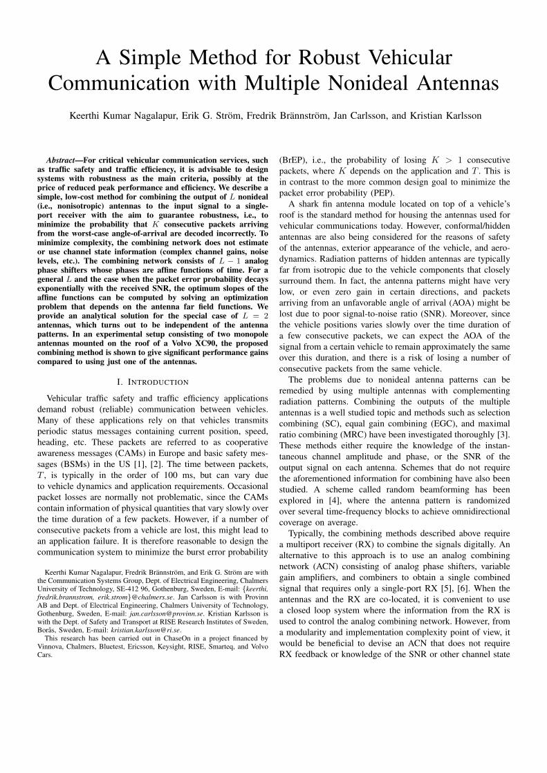
Fig. 1. The analog combining network with L antennas.
adder as seen in Fig. 1. The outputs of the L−1 antennas arephase rotated and added to the output of the reference antenna.The output of the combiner r(t) is given by
r(t) =
L−1∑l=0
rl(t)eϕl(t),
where ϕl(t) is the time-varying phase shift applied to the lthantenna output and ϕ0(t) = 0. For simplicity, we let
ϕl(t) = αlt+ βl, l = 0, 1, . . . , L− 1.
Hence, αl is the phase slope and βl is the phase offset of thelth phase shifter, and α0 = β0 = 0 (since ϕ0(t) = 0). Theoutput of the ACN is
r(t) = s(t)a(t)
L−1∑l=0
gl(φ)e−(Ωl−αlt−βl)
︸ ︷︷ ︸g(φ,α,β,t)
+
L−1∑l=0
nl(t),
where g(φ,α,β, t) is the effective time-varying antenna far-field function, α = [α1, . . . , αL−1]
T, β = [β1, . . . , βL−1]T,
and nl(t) = nl(t)eφl(t) has the same distribution as nl(t)
since nl(t) is circularly symmetric.When the phase shift, ϕl(t), over a packet duration is neg-
ligible, g(φ,α,β, t) remains approximately constant over theduration of a packet, and the effective far-field function duringthe kth packet can be approximated to be g(φ,α,β, kT ).Consequently, the average SNR of the kth packet is givenby
γ(φ,α,β, k)=E|a(t)s(t)|2
|g(φ,α,β, kT )|2
E∣∣∣∑L−1
l=0 nl(t)∣∣∣2
=Pr
LPn|g(φ,α,β, kT )|2,
where Pr is the received signal power from an ideal isotropicantenna.
The packet error probability Pe(γ) is a function of theaverage SNR that depends on modulation, coding, packet
length, and channel characteristics. For simplicity, we modelthe PEP function as
Pe(γ) = a exp(−bγ), (2)
where a, b > 0 are constants. As mentioned earlier, we intendto minimize the probability of having a burst of K consecutivepacket errors. Assuming that packet error events are statisticalindependent2, the BrEP is
PB(φ,α,β,K) =
K−1∏k=0
Pe(γ(φ,α,β, k))
=
K−1∏k=0
ae−bγ(φ,α,β,k).
Since we want to determine the optimum α that minimizesthe BrEP for the worst-case AOA φ ∈ [0, 2π) and worst-caseinitial offset βl ∈ [0, 2π), the optimum α is found as
α? = arg infαl∈R
supφ,βl∈[0,2π)
PB(φ,α,β,K)
= arg infαl∈R
supφ,βl∈[0,2π)
lnPB(φ,α,β,K)
= arg supαl∈R
infφ,βl∈[0,2π)
K−1∑k=0
γ(φ,α,β, k)
= arg supαl∈R
infφ,βl∈[0,2π)
K−1∑k=0
Pr
LPn|g(φ,α,β, kT )|2
= arg supαl∈R
infφ,βl∈[0,2π)
K−1∑k=0
∣∣∣∣∣L−1∑l=0
gl(φ)e−(Ωl−αlkT−βl)
∣∣∣∣∣2
.
Let ψl = mod (Ωl − βl − ∠gl(φ), 2π), where mod (u, v) isthe remainder after dividing u by v. Now, varying βl in theinterval [0, 2π) for fixed Ωl and ∠gl(φ) implies that ψl takeson all values in [0, 2π). Hence, the optimization problem canbe rewritten as
α? = arg supαl∈R
infφ,ψl∈[0,2π)
K−1∑k=0
∣∣∣∣∣L−1∑l=0
|gl(φ)| e−(ψl−αlkT )
∣∣∣∣∣2
︸ ︷︷ ︸J(φ,α,ψ,K)
.
(3)For L = 2, a closed-form solution to (3) is given by
Theorem 1 below. Due to space constraints, we postpone atreatment of the general case, L > 2, to an upcoming journalpaper.Theorem 1. Let J(φ,α,ψ,K) be defined as in (3). Then, foran arbitrary φ and for K ≥ L = 2,
J?(φ) , supα1
infψ1
J(φ, α1, ψ1,K) = K(|g0(φ)|2 + |g1(φ)|2)
Moreover, the optimum is obtained for
α1 = α?1 ,2π
KT.
2Error events are independent if noise is independent from packet topacket, which is a standard assumption, and if any small-scale fading is alsoindependent from packet to packet, i.e., when the coherence time is smallcompared to T , which typically is the case for highway mobility.
Proof: See Appendix.
We note, somewhat surprising, that α?1 does not depend onthe antenna patterns. Moreover, as shown in the appendix,J(φ, α?1, ψ1) = K(|g0(φ)|2 + |g1(φ)|2), which is independentof ψ1 and, therefore, independent of β1. Hence, for any initialoffset β1, the worst-case AOA φ, i.e., the AOA that results inthe highest BrEP is given by
φ? = arg minφ∈[0,2π)
|g0(φ)|2 + |g1(φ)|2 .
As a consequence, when the proposed combining scheme isused, the antennas should be designed and oriented such that|g0(φ?)|2 + |g1(φ?)|2 is maximized.
III. COMPARISON WITH STANDARD SCHEMES
In this section, the performance of the proposed combiningscheme is compared with a few standard combining schemes.In the case when the PEP function is exponential as in (2),minimizing the BrEP is equivalent to maximizing the sumof the average SNRs of the K packets. Therefore, the sumof SNRs is used as a performance criterion to compare theperformance of the combining schemes.1) Single antenna: the sum of average SNRs at the output of
the lth antenna is given by
ρl(φ) =
K−1∑k=0
γl(φ, k) =KPr
Pn|gl(φ)|2 .
For an ideal isotropic antenna, the sum of average SNRsis given by ρISO(φ) = KPr/Pn.
2) MRC: this scheme requires L RF-chains, L analog todigital converters (ADCs), and a multi-port receiver thatestimates the complex-valued channel gains and performscombining digitally. The sum of average SNRs is given by
ρMRC(φ)=
K−1∑k=0
γMRC(φ, k)=KPr
Pn
(L−1∑l=0
|gl(φ)|2).
3) EGC: this scheme requires L RF-chains, L ADCs, and amulti-port receiver that estimates the channel phases andperforms combining digitally. The sum of average SNRs isgiven by
ρEGC(φ)=
K−1∑k=0
γEGC(φ, k)=KPr
LPn
(L−1∑l=0
|gl(φ)|)2
.
4) SC: this scheme requires L RF-chains and circuitry tomeasure the SNRs on each antenna and to select anantenna. The sum of average SNRs is given by
ρSC(φ)=
K−1∑k=0
γSC(φ, k)=KPr
Pnmaxl|gl(φ)|2 .
5) ACN: the proposed scheme requires analog phase shifterson L−1 branches operating independently and a combiner.For L = 2 and α1 = α?1, the sum of average SNRs is
ρACN(φ) =KPr
2Pn(|g0(φ)|2 + |g1(φ)|2).

Fig. 2. Antenna placement on the roof of a Volvo XC90.
0
30
60
90
120
150
180210
240
270
300
330
−25
−15
−5
5
15φ =
ρ(φ)
indB
ρ0(φ)
ρ1(φ)
ρACN(φ)
ρISO(φ)
ρEGC(φ)
Fig. 3. ρ(φ) of the two monopoles mounted on the roof of a vehicle andthe ACN. The monopoles exhibit nonisotropic power gains. Pr/Pn = 1 andK = 5.
We note that the sum of average SNRs for MRC and ACNfor L = 2 are related as ρMRC(φ) = 2ρACN(φ).
The MRC scheme outperforms EGC, SC, and ACN for anyfar-field functions gl(φ). The relative performance of SC andEGC for an AOA φ depends on the far-field functions gl(φ).The sum of average SNRs of MRC, EGC, and SC schemes ishigher compared to the ACN scheme, implying lower BrEP.However, these gains come at a cost of additional hardwareand/or signal processing as mentioned above.
0 50 100 150 200 250 300 35010−7
10−6
10−5
10−4
10−3
10−2
10−1
100
EGC ISO
φ in degree
PB(φ,α
∗ ,β,K
)
Ant. 0 Ant. 1 ACN
Fig. 4. BrEP as a function of AOA φ for the individual antennas and thecombined output when K = 5, α1 = α?
1 = 2π/(KT ).
IV. NUMERICAL RESULTS
In this section, the performance of the ACN is studiedby using the measured antenna far-field functions of twomonopole antennas placed 0.8 m from each other on the roofof a Volvo XC90, see Fig. 2. The sum SNRs ρ0(φ) andρ1(φ) for Pr/Pn = 1 and K = 5 are shown in Fig. 3.As seen in the figure, both antennas exhibit very low ρ(φ)at certain, but different, AOAs. Clearly, if only one of thetwo antennas is used, the packets arriving in the AOAs oflow ρ(φ) will have high BrEP. However, by combining theoutput of the antennas with the proposed ACN, the BrEP isreduced compared to using the antenna with the lowest gain(since ρACN(φ) ≥ minl ρl(φ)). The sum of average SNRs inthe case of a single isotropic antenna and in the case of themeasured antennas combined using EGC are also shown inthe figure. The plots corresponding to MRC and SC have beenomitted. However, they are related to the plots in the figureas ρMRC(φ) = 2ρACN(φ) and ρSC(φ) = max ρ0(φ), ρ1(φ).As expected, the more advanced combining methods performbetter than the proposed ACN.
Fig. 4 shows the BrEP as a function of AOA for the indi-vidual antennas and the ACN. The exponential PEP functionPe(γ) = exp(−γ/5) is considered and Pr/Pn = 10 dB isused. It is seen that the BrEP in the case of the individualantennas is very close to 1 for the AOAs that have very lowρl(φ) (see Fig. 3). The BrEP for the AOAs corresponding tolow gains in one of the two antennas is reduced by the ACN.The BrEP for certain AOAs when using the ACN is higher incomparison to one of the individual antennas, this is expectedas the ACN operates without the knowledge of branch SNRsand the complex-valued channel gains. The figure also showsthe BrEP in the case of a single isotropic antenna and in thecase of the measured antennas combined using EGC, the BrEPin these cases is in agreement with their ρ(φ) in Fig. 3.

V. CONCLUSIONS
In this paper, we have proposed to use a simple analogcombining network consisting of L − 1 phase shifters tocombine the outputs of L nonisotropic antennas to the input ofa single-port receiver with the goal to minimize the burst-errorprobability, i.e., the probability of K consecutive packet errors,for the worst-case angle of arrival. The combining networkis defined by the offset and slope of the phase shifters anddoes not require knowledge of the channel state (SNR, fadingstatistics, etc.). For a general L and when the PEP decays ex-ponentially with the received SNR, the optimum phase slopescan be found by solving the optimization problem (3). ForL = 2, the combining network contains a single phase shifter,and the optimum phase slope is proven to be α?1 = 2π/(KT ),where T is the time between consecutive packets. Somewhatsurprising, this result is valid for all initial phase offsets andantenna patterns and will improve the BrEP for all AOAscompared to using the worst antenna. Hence, we cannot furtherimprove performance by optimizing the initial phase offset β1.However, the BrEP for AOA φ is minimized by maximizing|g0(φ)|2 + |g1(φ)|2.
The proposed scheme was evaluated using the measured far-field functions of two monopole antennas placed on the roofof a Volvo XC90. It was shown that the proposed schemegives significant performance gains by combining the antennaoutputs compared to just using one of the antennas. Thestandard MRC, EGC, and SC combining schemes performeven better, but will also require channel state informationand more complex receiver circuitry.
APPENDIX
To set up the proof for Theorem 1, we start by proving twolemmas. Define the function f : R2 → R as
f(x, y) ,K−1∑k=0
cos(y − k2x), (4)
where K > 1 is a positive integer. It can be shown that
f(x, y) =
K cos(y), x ∈ Xsin(Kx)
sin(x)cos(y − (K − 1)x), x /∈ X (5)
whereX , qπ : q ∈ Z. (6)
Lemma 1. Let f and X be as defined in (4) and (6),respectively. Then,
f(x, y) = 0, x ∈ X ?, y ∈ R,
whereX ? , qπ/K : q ∈ Z \ X . (7)
Proof: If x ∈ X ? then x /∈ X , then (5) implies that
f(x, y) =sin(Kx)
sin(x)cos(y − (K − 1)x), x ∈ X ?.
The lemma follows since sin(Kx)/ sin(x) = 0 iff x ∈ X ?.
Lemma 2. Let f and X ? be as defined in (4) and (7),respectively. Then,
infy∈R
f(x, y) ≤ 0
where equality is achieved iff x ∈ X ?.Proof: From Lemma 1, we know that f(x, y) = 0 for
x ∈ X ? and all y ∈ R. To show the lemma, it is thereforesufficient to show that infy f(x, y) < 0 for x /∈ X ?. We splitup the condition x /∈ X ? into two cases, (a) x ∈ X and (b)x ∈ X ′ , R⋂X ⋂X ?. For case (a): f(x, y) = K cos(y)and infy f(x, y) = −K < 0. For case (b):
f(x, y) =sin(Kx)
sin(x)︸ ︷︷ ︸6=0,∀x∈X ′
cos(y − (K − 1)x).
Clearly, there exist a y such that cos(y − (K − 1)x) =− sgn[sin(Kx)/ sin(x)], which implies that infy f(x, y) =−| sin(Kx)/ sin(x)| < 0. Hence, the lemma follows.
We are now ready to prove Theorem 1.Proof: It is easily shown that the objective in (3) for
L = 2 can be written as
J(φ, α1, ψs,K) = K(|g0(φ)|2 + |g1(φ)|2)
+ 2|g0(φ)||g1(φ)|f(x, y),
where x = α1T/2 and y = ψ0−ψ1. From Lemma 2, we havethat supx infy f(x, y) = 0. Hence,
J?(φ) = supx
infy
K(|g0(φ)|2 + |g1(φ)|2)
+ 2|g0(φ)||g1(φ)|f(x, y)
= K(|g0(φ)|2 + |g1(φ)|2).
Moreover, from Lemma 2, we know that the supremum isachieved for x ∈ X ?, i.e., for α1 ∈ 2x/T : x ∈ X ?.The smallest nonzero optimum phase slope is therefore α?1 =2π/(KT ), and the theorem follows.
REFERENCES
[1] “Intelligent transport systems (ITS); vehicular communications; basicset of applications; part 2: specification of cooperative awareness basicservice,” ETSI TS 102 637-2 (V1.2.1), 2011.
[2] “Dedicated short range communications (DSRC) message set dictionary,”SAE Standard J2735, Mar. 2016.
[3] A. Goldsmith, Wireless communications. Cambridge University Press,2005.
[4] X. Yang, W. Jiang, and B. Vucetic, “A random beamforming techniquefor omnidirectional coverage in multiple-antenna systems,” IEEE Trans-actions on Vehicular Technology, vol. 62, no. 3, pp. 1420–1425, Mar.2013.
[5] V. Venkateswaran and A. J. van der Veen, “Analog beamforming inMIMO communications with phase shift networks and online channelestimation,” IEEE Transactions on Signal Processing, vol. 58, no. 8, pp.4131–4143, Aug. 2010.
[6] F. Gholam, J. Via, and I. Santamaria, “Beamforming design for simplifiedanalog antenna combining architectures,” IEEE Transactions on VehicularTechnology, vol. 60, no. 5, pp. 2373–2378, June 2011.
[7] J. Karedal, F. Tufvesson, N. Czink, A. Paier, C. Dumard, T. Zemen,C. Mecklenbrauker, and A. Molisch, “A geometry-based stochastic MIMOmodel for vehicle-to-vehicle communications,” IEEE Transactions onWireless Communications, vol. 8, no. 7, pp. 3646–3657, July 2009.