A SIMPLE AND RELIABLE TOUCH SENSITIVE SECURITY SYSTEM
17
International Journal of Network Security & Its Applications (IJNSA), Vol.4, No.5, September 2012 DOI : 10.5121/ijnsa.2012.4512 149 A SIMPLE AND RELIABLE TOUCH SENSITIVE SECURITY SYSTEM Adamu Murtala Zungeru 1 , Jonathan Gana Kolo 2 and Ijarotimi Olumide 3 1,2 School of Electrical and Electronic Engineering, University of Nottingham, Jalan Broga, 43500 Semenyih, Selangor Darul Ehsan, Malaysia [email protected], [email protected] 3 Electrical and Electronic Engineering Technology, Rufus Giwa Polytechnic, Owo, Ondo, Nigeria [email protected] ABSTRACT This research focuses on detection of unauthorized access to residential and commercial buildings when the residents are far away from the access gate of the house. The system is a simple and reliable touch activated security system and uses sensor technology to revolutionize the standards of living. The system provides a best solution to most of the problems faced by house owners in their daily life. Due to its simple electroniccomponents nature, it is more adaptable and cost-effective. The system is divided into threeunits; the power supply unit which employs the use of both DC battery and mains supply to ensure constant power supply to the circuit, the trigger unit which is responsible for activating the alarm unit and designed to have much time and period and moderate sensitivity in order to reduce the rate of false alarm, and the alarm amplitude unit which main function is to produce amplitude alarm sound when triggered by the trigger unit with the aim of producing a large audible sound that can alert the entire neighborhood or scare an intruder away. The design of the system was achieved by considering some factors such as economy, availability of components and research materials, efficiency, compatibility and portability and also durability in the design process. The performance of the system after test met design specifications. This system works on the principle of touch sensor.The general operation of the system and performance is dependent on the presence of an intruder entering through the door and touching any part of the door. The overall system was constructed and tested and it work perfectly. KEYWORDS Touch Sensor, Automation,Control System, Security, Electronic Circuit, Maximum Power Transfer 1. INTRODUCTION Insecurity and crime constitute some of the major problems facing our immediate society today. People live with fear of being attacked by burglars, vandals and thieves. Despite all the effort, resources and time that has been devoted to the development of tools that will reduce crime rates and make the world a safer place to live, these problems are still on the increase.These gave rise to the need for an increasing development in the technology of alarm systems which utilizes various principles such as infrared motion detection, light (photo) sensitive electronic devices and so on. Even with the introduction of these alarm systems which have reduced greatly the level of insecurity, there is still a problem of false alarm which needs to be minimized [1]. In order to effectively reduce the level of insecurity and avoid false alarms which can create unnecessary unrest, a touch activated security system is required. This system if properly designed will provide security and ensure alarms are activated only when an unauthorized person try to gain access to the protected area or device by touching the entrance or any other part of the device.
Transcript of A SIMPLE AND RELIABLE TOUCH SENSITIVE SECURITY SYSTEM

International Journal of Network Security & Its Applications (IJNSA), Vol.4, No.5, September 2012
DOI : 10.5121/ijnsa.2012.4512 149
A SIMPLE AND RELIABLE TOUCH SENSITIVE
SECURITY SYSTEM
Adamu Murtala Zungeru1, Jonathan Gana Kolo
2and Ijarotimi Olumide
3
1,2School of Electrical and Electronic Engineering, University of Nottingham, Jalan
Broga, 43500 Semenyih, Selangor Darul Ehsan, Malaysia [email protected], [email protected]
3Electrical and Electronic Engineering Technology, Rufus Giwa Polytechnic, Owo,
Ondo, Nigeria [email protected]
ABSTRACT
This research focuses on detection of unauthorized access to residential and commercial buildings when
the residents are far away from the access gate of the house. The system is a simple and reliable touch
activated security system and uses sensor technology to revolutionize the standards of living. The system
provides a best solution to most of the problems faced by house owners in their daily life. Due to its
simple electroniccomponents nature, it is more adaptable and cost-effective. The system is divided into
threeunits; the power supply unit which employs the use of both DC battery and mains supply to ensure
constant power supply to the circuit, the trigger unit which is responsible for activating the alarm unit
and designed to have much time and period and moderate sensitivity in order to reduce the rate of false
alarm, and the alarm amplitude unit which main function is to produce amplitude alarm sound when
triggered by the trigger unit with the aim of producing a large audible sound that can alert the entire
neighborhood or scare an intruder away. The design of the system was achieved by considering some
factors such as economy, availability of components and research materials, efficiency, compatibility and
portability and also durability in the design process. The performance of the system after test met design
specifications. This system works on the principle of touch sensor.The general operation of the system
and performance is dependent on the presence of an intruder entering through the door and touching any
part of the door. The overall system was constructed and tested and it work perfectly.
KEYWORDS
Touch Sensor, Automation,Control System, Security, Electronic Circuit, Maximum Power Transfer
1. INTRODUCTION
Insecurity and crime constitute some of the major problems facing our immediate society today.
People live with fear of being attacked by burglars, vandals and thieves. Despite all the effort,
resources and time that has been devoted to the development of tools that will reduce crime
rates and make the world a safer place to live, these problems are still on the increase.These
gave rise to the need for an increasing development in the technology of alarm systems which
utilizes various principles such as infrared motion detection, light (photo) sensitive electronic
devices and so on. Even with the introduction of these alarm systems which have reduced
greatly the level of insecurity, there is still a problem of false alarm which needs to be
minimized [1]. In order to effectively reduce the level of insecurity and avoid false alarms
which can create unnecessary unrest, a touch activated security system is required. This system
if properly designed will provide security and ensure alarms are activated only when an
unauthorized person try to gain access to the protected area or device by touching the entrance
or any other part of the device.

International Journal of Network Security & Its Applications (IJNSA), Vol.4, No.5, September 2012
150
An alarm is a loud noise or signal for alerting or informing people of danger or a problem. An
alarm system is thus a security system that produces a form of sound to warn people of a
particular danger. The development of alarm systems started with the creation of man. Man
required giving alert information and adopted a form of signaling, exclamation and shouting.
This was later replaced by clapping of hands and beating of gongs by town criers to alert the
community in order to disseminate information in the early African society. All these methods
of raising alert were crude, unreliable and inefficient.
With the advancement in science and technology, these crude methods of generating alarm were
replaced by electronic alarm systems in the late eighteenth century [2]. These electronic alarm
systems operate without any human effort.Once it senses a particular signal, it gives an
indication in form of loud sound or noise depending on its design [3].The first electronic fire
alarm system was developed by Dr. William f. Channing and constructed by Mr.-Moses G.
Farmer, an electrical engineer [4]. This system uses boxes with automated signaling to indicate
the location of fire and was first put into operation in Boston in the UnitedState of America
(U.S.A).The development of this alarm system by Dr William was followed with the evolution
of fire and burglar alarm technology of varying complexities and sophistications which are too
numerous to mention. Notable among these technologies is the remote signaling intruder alarm
system which was invented in the early 1970’s [2]. This provided a rapid art full response to
alarm calls.
However, industries based on security service equipment provision have being coming up with
different designs so as to keep burglars and vandals away from public areas not made for them
[5]. Today we have the new generation of electronic alarm system which comes in various
levels of complexities and sophistication [6]. With the recent increase in crime rates, it has
become important to protect our buildings and properties with adequate safety devices with
increased level of sophistication [5]. The cost of these safety devices depend on the equipment
technology and the application requirement. These safety devices are called the modern
electronic alarm system [7].Some of the modern alarm systems commonly used these days is
burglar alarms, duress alarms, industrial alarms, speed limit alarms, and anti-theft car alarms.
The burglar alarm is made from a complete electronic circuit loop where by the loop is closed
with a bell at the output or a siren so as to alert the owner of what so ever is to be secured. A
central control box monitors several motion detectors and perimeter guards and sound an alarm
when any of them are triggered. Some burglar alarms work on the concept of magnetic contacts
and others on sensitivity. For those that work on sensors, the sensors are normally placed in the
entrance of any of the building or restricted entrance of the rooms, in which if the sensor receive
a signal above the threshold value set for it, it activate an alarm[7]. In the case of motion
detection, ultrasonic method is normally utilized, whereas point detector burglar alarm helps in
the detection of theft or unauthorized person at a particular point or a location such as doors or
windows. For example, when a particular area is to be monitored, area detection of intruders is
utilized within the protected space or location, this is with the help of ultrasonic transducers
and/or passive infrared sensors (IR), and are normally mounted at an appropriate location.
Nowadays, closed circuit televisions are incorporated to burglar alarms to detect the presence of
unauthorized persons. The output of burglar alarm systems can range from siren or loud alms to
telephone automatic dialers and flashing outdoor lights. This serves the function of alerting the
neighbors of possible intrusion and also serves as a signal to the police [8]. Auto dialers
attached to burglar alarms are programmed to dial the police and play a pre recorded message
that informs the police of the house being burgled.
The increasing developments in science and technology have given rise to a tremendous
improvement in the technology of alarm sensors. These sensors act as inputs which triggers the
alarm. Some of the alarm sensor technologies that have evolved over the years are (1)
Microwave sensors: These are motion detection devices that flood a designated area or zone

International Journal of Network Security & Its Applications (IJNSA), Vol.4, No.5, September 2012
151
with an electronic field. A movement in the zone or area disturbs the speed and sets off the
alarm [9]. (2) Vibration Sensors: The vibration sensors are usually mounted on walls, ceiling
and floor with the intention of detecting mechanical vibrations caused by chopping, drilling or
any type of physical intrusion [9]. (3) Photo electric beam sensor: These types of sensors
transmit infrared rays in the form of light beam to a receiver which is normally in a remote area,
hence creating an electronic fence. These sensors are often used to cover openings such as
doorways or hall ways acting essentially as trip wire. Once the beam is broken or interrupted, an
alarm signal is generated [9]. (4) Electrical field sensors: These sensors generate an electrostatic
field between and around an array of conductors and an electrical ground. They detect changes
or distortion in the field. This can be caused by anyone approaching or touching the sensor [9].
(5) Audio sensors: These sensors respond to noise generated by intruders entry into a protected
area and are generally used but exclusively for internal application. (6) Capacitance sensors:
These sensors detect changes in electric field. When a signal is generated, which is either below
or higher in value than the threshold signal level when an intruder happens to effect changes in
the capacitance of the field, which is as a result of the intruder getting closer to or by direct
contact with the sensor wire [9].
The alarm sensor technology employed in this system is the capacitance sensor. The sensor’s
wire is usually attached to metallic door handles, metallic, and protectors etc. It normally
require touch or close proximity and subsequent alteration of capacitance to trigger the alarm.
This sensor type adopted in this system helps in the reduction of false triggering of alarms and
the detection of intruders is not in any way affected by weather condition, radio frequency or
electromagnetic disturbance.
The problem of frequent power outages in some part of the world today gave rise to the use of
an automatic power change over switch which has the ability of switching between the mains
supply and DC battery using a relay. This provides a passive (or standby) redundancy for the
power supply to the alarm system thereby increasing its reliability.The system has both security
application and luxury, since it is more comfortable and easy for an intruder to be automatically
detected without the need to employ a security guard.
This article is outline in to five major sections. The First Section gives a general introduction of
a simple and reliable touch sensitive security system. Section two gives presentation of related
works to the aim of this research. In Section Three, detail descriptions of the design and
implementation procedures are presented. Section Four presents the experimental results and
discussion of the results. In Section Five, we conclude the work with some recommendations.
Finally, references used in the manuscript are presented at the end of the paper.
2. RELATED WORK
The idea of using sensing devices for convenience, safety, security and quality of service
purpose is not new, but the application, cost, design method and reliability of the system varies.
In [10,11], the authors consider the use of infra-red rays to count the number of passengers in a
car and also remotely control home appliances via short message services for the purpose of
security and human convenience. In [3, 5], [8], a burglar alarm system was designed. The
burglar alarm is made from a complete electronic circuit loop where by the loop is closed with a
bell at the output or a siren so as to alert the owner of what so ever is to be secured. A central
control box monitors several motion detectors and perimeter guards and sound an alarm when
any of them are triggered. Some burglar alarms work on the concept of magnetic contacts and
others on sensitivity. For those that work on sensors, the sensors are normally placed in the
entrance of any of the building or restricted entrance of the rooms, in which if the sensor receive
a signal above the threshold value set for it, it activate an alarm.
Nowadays, closed circuit televisions are incorporated to burglar alarms to detect the presence of
unauthorized persons. The output of which is normally a siren or loud speaker alarms to

International Journal of Network Security & Its Applications (IJNSA), Vol.4, No.5, September 2012
152
telephone automatic dialers or lighting systems. This serves the function of alerting the
neighbors of possible intrusion and also serves as a signal to the police [8]. Auto dialers
attached to burglar alarms are programmed to dial the police and play a pre recorded message
that informs the police of the house being burgled. In a related work [12], a Modern duress
alarm was considered, and is generally electronic devices that vary widely in capabilities. They
are used when under threat to send alarm signals to specific location, and are normally
categorized as duress alarm systems. The types of duress alarm systems are:
(i) Identification alarm: In this system, a simple portable device is used to identify the
access able personnel (owner) of the device.
(ii) Panic button alarm. A push button mounted in a fixed location.
(iii) A location alarm: a portable device that locates and tracks the person who activated
alarm.
The panic button is the most common type of duress alarm. It is found in schools, banks, offices
etc. A pre recorded message specifying the location and urgency is sent to several locations such
as police department or other security agencies whenever there is a trigger of the system.When
the panic button is pushed, a wireless signal is transmitted to the nearest installed wireless
repeater unit, which sends the signal to an alarm console. This system does not give specific
locations other than the general pre programmed zone of the repeater.The location alarm is a
similar version of the identification. The electronics and software of such a system produces a
positioning symbol on a console panel or map like display.
Besides, most of the papers mentioned above does not consider cost, reliability and durability in
their design procedure, and above all, this paper uses simple and easy to get components to
achieve its desired goals.
3. SYSTEM DESIGN AND IMPLEMENTATION
This section will discuss the design procedure and the basic theory of components used for this
work. The section is further divided into two sub-sections as design theory and system design
analysis.
3.1. Stages of Implementation
The system design was implemented in three units as shown in Fig. 1. These units are:
(A) The power supply unit
(B) The trigger unit
(C) The alarm/amplifier units

International Journal of Network Security & Its Applications (IJNSA), Vol.4, No.5, September 2012
153
Fig. 1: Block diagram of a touch activated security system
3.1.1. Power Supply Unit
The power supply unit is a 2-way automatic power supply system. It gets input from both mains
supply and battery supply. The two independent supply systems are connected to a relay switch
which acts as an automatic change over switch to switch on any of the available input supply to
the main circuit. The power supply unit provides power supply to the other two units of the
circuit.
Fig. 2: The schematic diagram of the power supply unit is shown below.
The schematic diagram of the power supply unit consists of two supply input sources (i.e. mains
supply and 12V D.C supply from battery). F1 is a protective fuse used to prevent excess current
from entering the circuit. T1 is a step down transformer. D1, D2, D3, and D4 are rectifier
diodes. C1 is a filter capacitor. IC1 is a regulator IC. Rly1 is a relay switch. R1 and R2 are
current limiting resistors protecting LED1 and LED2 respectively.
LED1 is used to indicate the presence of mains supply while LED2 is used to indicate that
current is entering the trigger unit. D5 andD6 are protective diodes.

International Journal of Network Security & Its Applications (IJNSA), Vol.4, No.5, September 2012
154
3.1.1.1. Operation of the Power Supply Unit
The operation of the power supply unit can be illustrated by the block diagram shown in Fig. 3
below.
Fig.3: Block diagram of the power supply unit
The block diagram consist of 4 stages for rectification of 240V (A.C)mains supply to 12V
(D.C), a battery supply and a relay switch. The description of each stage is given below:
3.1.1.2. Transformer Stage
This stage consists of a 240V/18V, step down transformer. It converts the 240V (A.C) voltage
supply from mains to 18V (A.C), a 1A fuse (F1) was incorporated at the primary side of the
transformer to protect it from excess current. The 18V (A.C) supply is then passed to the
rectifier stage. A 220V/18V step down transformer was chosen because the regulator used
required more than 12V for its operation.
3.1.1.3. Rectifier Stage
In this stage, the rectifier converts the 18V (A.C) supply from the transformer into a
pulsatingD.C voltage. A full bridge rectifier was used for this purpose. It consist of four diodes
(IN 4001 series) arranged as shown in Fig. 2. During the positive half cycles diodes D2 and D3
are forward biased and current flows through the terminals. In the negative half cycle, diodes
D1 and D4 are forward biased. Since load current is in the same direction in both half cycles,
full wave rectifier signal appears across the terminals [13].

International Journal of Network Security & Its Applications (IJNSA), Vol.4, No.5, September 2012
155
3.1.1.4. Filter Stage
The pulsating D.C voltage that comes out from the rectifier stage is converted into constant D.C
voltage with the aid of a filter capacitor (C1). This capacitor is large value electrolytic capacitor.
It charges up (i.e. store energy) during the conduction half cycle thereby opposing any changes
in voltage. The filter stage therefore filters out voltage pulsations (or ripple).
3.1.1.5. Regulator Stage
The output of the filter stage varies slightly when the load current or output voltage varies and it
isan 18V D.C supply which is higher than the circuit requirement. For these reasons, an LM
7312 Regulator was used to stabilize the voltage and also reduce it from 18V to a 12V steady
D.C supply.
3.1.2. The Trigger Unit
Below is the schematic diagram of the trigger unit:
Fig. 4: Circuit diagram of the trigger unit
As shown in Fig. 4, the schematic diagram of the trigger unit consist of 3 major components
which areNE555 timer (IC2), Transistor (TR1) and a relay (RLY2).The 555 timer (IC2)
produces a trigger current which comes out through its pin 3 whenever pin 2 is activated
through the sensor. Pins 4 and 8 are connected to positive power supply while pin 1 is grounded.
R3 and C2 determines the time out period of the 555 timer (i.e. the period at which the alarm
sound) while R4 determines the sensitivity of the sensor.The output from pin3 (trigger current)
is amplified by transistor (Tr1). R5 act as base resistor to Tr1 which is operating in common
emitter mode. The output current from transistor (Tr1) causes the relay (Rly2) to operate
thereby switching on the alarm/amplifier unit to power supply for duration of time determined
by the time out period of the 555 timer (IC2). D7 acts as a commutation diode protecting the
transistor (Tr1) from Back-EMF generated by the relay coils. The 555 timer in this unit operates
in a mono stable mode.
International Journal of Network Security & Its Applications (IJNSA), Vol.4, No.5, September 2012
156
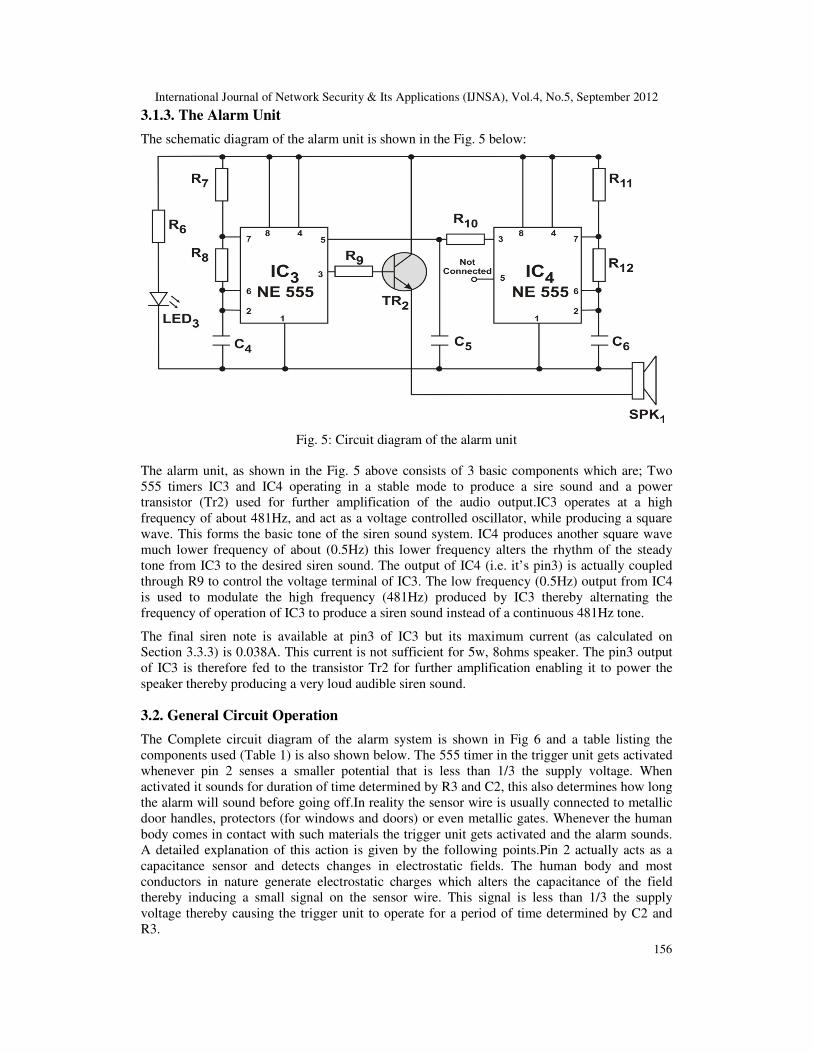
3.1.3. The Alarm Unit
The schematic diagram of the alarm unit is shown in the Fig. 5 below:
Fig. 5: Circuit diagram of the alarm unit
The alarm unit, as shown in the Fig. 5 above consists of 3 basic components which are; Two
555 timers IC3 and IC4 operating in a stable mode to produce a sire sound and a power
transistor (Tr2) used for further amplification of the audio output.IC3 operates at a high
frequency of about 481Hz, and act as a voltage controlled oscillator, while producing a square
wave. This forms the basic tone of the siren sound system. IC4 produces another square wave
much lower frequency of about (0.5Hz) this lower frequency alters the rhythm of the steady
tone from IC3 to the desired siren sound. The output of IC4 (i.e. it’s pin3) is actually coupled
through R9 to control the voltage terminal of IC3. The low frequency (0.5Hz) output from IC4
is used to modulate the high frequency (481Hz) produced by IC3 thereby alternating the
frequency of operation of IC3 to produce a siren sound instead of a continuous 481Hz tone.
The final siren note is available at pin3 of IC3 but its maximum current (as calculated on
Section 3.3.3) is 0.038A. This current is not sufficient for 5w, 8ohms speaker. The pin3 output
of IC3 is therefore fed to the transistor Tr2 for further amplification enabling it to power the
speaker thereby producing a very loud audible siren sound.
3.2. General Circuit Operation
The Complete circuit diagram of the alarm system is shown in Fig 6 and a table listing the
components used (Table 1) is also shown below. The 555 timer in the trigger unit gets activated
whenever pin 2 senses a smaller potential that is less than 1/3 the supply voltage. When
activated it sounds for duration of time determined by R3 and C2, this also determines how long
the alarm will sound before going off.In reality the sensor wire is usually connected to metallic
door handles, protectors (for windows and doors) or even metallic gates. Whenever the human
body comes in contact with such materials the trigger unit gets activated and the alarm sounds.
A detailed explanation of this action is given by the following points.Pin 2 actually acts as a
capacitance sensor and detects changes in electrostatic fields. The human body and most
conductors in nature generate electrostatic charges which alters the capacitance of the field
thereby inducing a small signal on the sensor wire. This signal is less than 1/3 the supply
voltage thereby causing the trigger unit to operate for a period of time determined by C2 and
R3.

International Journal of Network Security & Its Applications (IJNSA), Vol.4, No.5, September 2012
157
Fig
. 6:
Cir
cuit
dia
gra
m o
f a
sim
ple
and r
elia
ble
touch
act
ivat
ed s
ecuri
ty s
yst
em

International Journal of Network Security & Its Applications (IJNSA), Vol.4, No.5, September 2012
158
Table 1: Components List
SYMBOLS COMPONENTS RATING
T1 Transformer 240/18V,9V
F1 Fuse 1A
SPK1 Speaker 5 Watts, 8Ω
IC1 Linear Power Regulator LM7812
LED1, LED2, LED3 Light Emitting Diode NTE 3010
RLY1, RLY2 Relay Switch 12V, 400Ω
D1, D2, D3, D4, D5, D6, D7 Diodes 1N4001
C1 Capacitor 2200µF, 25V
C2, C5, C6 Capacitor 47µF, 25V
C3, C4 Capacitor 0.01µF
TR1 Transistor SC1815
TR2 Transistor TIP31
R1 Resistor 470Ω
R2 Resistor 980Ω
R3 Resistor 220KΩ
R4 Resistor 10.8MΩ
R5 Resistor 4.7KΩ
R6, R12 Resistor 1KΩ
R7, R8 Resistor 100KΩ
R9 Resistor 300KΩ
R10 Resistor 2.2KΩ
R11 Resistor 22KΩ
3.2.1. Monostable Operation of a Timing Circuit
The monostable mode of operation is as also known as one short operation of timing circuit.
When a negative-going trigger pulse is supplied to the trigger input, the threshold on the lower
comparator is exceeded, and this as well triggers the output circuit. The basic operation of the
circuit, and the duration of the output pulse in seconds is approximately equal to:
T = 1.1 x R x C (in seconds) (1)
3.2.2. Astable Operation of a Timing Circuit
In an Astable mode both the trigger and threshold inputs (pin 2 and 6) to the two comparators
are connected together and to the external capacitor. The frequency of operation of the Astable
circuit is dependent upon the values of Ra, Rb and C. the period can be calculated with the
formula:

International Journal of Network Security & Its Applications (IJNSA), Vol.4, No.5, September 2012
159
T = 0.693 x C (R1) (2)
The time difference between the ONtime and the OFFtime is mainly dependent on the value of
Ra and Rb. The ratio of the time duration when the output pulse is high to the total period is
known as the duty-cycle and is represented as:
( )( )ba
ba
RR
RR
t
tD
2
1
+
+= (3)
CRRt ba )(693.01 += (4)
xCxRt b693.02 = (5)
3.3. System Design Analysis
3.3.1. The Power Stage
A 240/18v transformer was chosen because its rating is capable of meeting the current demand
of the circuit and it is protected by the 1A fuse against excess current.The limiting resistor (R1)
for the LED1 was calculated as:
LEDcurrent
pVoltagedroR =1 (6)
=()
(7)
Where VCC = supply voltage = 18V, VLED = 2.2, ILED = maximum allowable current across the
LED = 35mA.
mA
VR
35
)2.218(1
−=
A
V
035.0
8.15=
Ω= 43.4511R
The preferred resistor value closest to 451.43 Ω is 470 Ω . Therefore 470 Ω were adopted in the
design.
Current drawn by LED1
Ω=
470
18VMA038.0=
The peak inverse voltage (PIV) obtainable at the secondary terminal transformer is twice the
terminal voltage VS[13].
That is: PIV = 2 x Vs = 2 x 18 = 36V.
At the full bridge rectifier circuit IN4001 diode was used because its PIV which is 50V is
greater than the PIV of the secondary of the secondary terminal which is 36V[13]. This was
done to avoid damage to the diodes in case reverse operation occurs.The value of the filter
capacitor C1 was obtained as:
fyRC
34
1= (8)
(For full wave rectifier circuits)[13], where: f = frequency of ripple voltage = 50Hz

International Journal of Network Security & Its Applications (IJNSA), Vol.4, No.5, September 2012
160
y = ripple factor = 5% = 0.05
R = resistance of the regulator =I
V
(9)
V = Constant output voltage from the regulator = 12v, I = Constant output current from the
regulator = 500mA = 0.5A
Ω== 245.0
12R
05.0502434
1
xxxxC =
, 692.415
1=C
LEDcurrentxC 6104056.2 −= , FxC µ6.405.2=
A 2200 Fµ was used in the design because it is the closest value of a standard capacitor of
Fxµ6.405.2 . The current limiting resistor for LED2 is calculated as shown below:
LEDcurrent
pVoltagedroR =2
)(
)(2
LEDI
LEDVVccR
−=
Where VCC = supply voltage = 12V, VLED = 2.2, I (LED) = 0.01A (Chosen to limit the amount
of current consumed by the LED)
A
VR
01.0
)2.212(2
−= ,
A
VR
01.0
8.92 =
Ω= 9802R
The preferred resistor value closest to 980 Ω is 1K Ω . Therefore 1K Ω resistor was adopted as
R2 in the design.
Current drawn by LED2 = Ω1000
12VA012.0= mA12=
3.3.2. The Trigger Stage
The timeout period (T) and the frequency (f) were determined by the values of R4 and C2 as
follows:
)(1.1 23 xCRT = (10)
But R3 = 220KΩ = 220 x 103Ω, C2 = 47µF = 47 x 10
-6F
sxxxT sec)104722010220(1.1 63 −= sx sec)34.101.1(=
ss sec11sec374.11 ≈=
Tf
1=
374.11
1= Hz09.0=

International Journal of Network Security & Its Applications (IJNSA), Vol.4, No.5, September 2012
161
The values of R4 and C2 were chosen in such a way that they can produce an approximate period
of 11secs delay.The basis resistor R5 for transistor Tr1 was chosen as a result of the following
calculations:
B
BE
I
VVccR
−=6
(11)
Where VCC = supply voltage = 12V, VBE = Base emitter voltage = 0.6(see appendix III)
IB= Base current
IB = IC/gain Supply voltage, Gain = 25 (hFE)
IC= collector current = maximum Relay current = AcesisCoil
ageSupplyVolt03.0
400
12
tanRe==
AI B 0012.025
03.0==⇒
To ensure that the current is sufficient to drive the transistor into saturation, the quantity of the
current is doubled i.e.
AxI B 024.020012.0 ==
0024.0
4.11
0024.0
6.0125 =
−=R
KΩ≈Ω 7.447050
A KΩ7.4 resistor was chosen to serve as the base resistor (R6) to the transistor because it is
the closet value of standard resistor value to 47050 Ω .
3.3.3. The Alarm/Amplifier Stage
Design calculation for this unit was done in three stages.
Stage 1:This is the high frequency oscillator stage. The period (TH) and frequency (fH) for this
stage were calculated as follows:
TH = t1 + t2 (12)
t1 = 0.693 x C4 (R7 + R8)
But C4 = 0.01µF = 0.01 x 10⁻⁶F
R7 = R8 = 100KΩ =100 x 103Ω
Therefore, t1 = 0.693 x 0.01 x 10-6(100 x 103 + 100 x 103)
= 0.693 x 0.01 x 10-6 x 200 x 103= 1.386 x 10⁻³secs
t2= 0.693 x 100 x 103 x 0.01 x 10-
6
t2= 0.693 x 10⁻³
-3 3
21H 100.693x 10 x 1.386 t tT +=+=∴ =2.079 x 10⁻³
secs = 2.079msecs
310097.2
11−
==xT
FH
H = 481Hz

International Journal of Network Security & Its Applications (IJNSA), Vol.4, No.5, September 2012
162
Duty cycle = %10010097.2
31038.13
1 xx
x
T
t
H
−
−= =66.95%
The value of C4, R7 and R9 were manipulated in order to get the desired frequency that will
modulate the low frequency oscillator (IC2) to give the desired tone.
Stage 2:This is the low frequency oscillator stage. The period (TL) and frequency (FL) for this
were calculated as follows:
= + (13)
t1 = 0.693 x C6 (R11 + R12)
But C6 = 47µF = 47 x 10-6
F
R11 = 1KΩ = 1 x 10³ Ω
Therefore, t1 = 0.693 x 47 x 10-6 (1 x 10³ + 22 x 103)= 0.693 x 47 x 10-6 x 23 x 103
= 10741.003x 10-3
secs= 1.041secs
t2 = 0.693 x C6 xR12
t2 = 0.693 x 47 x 10-6 22 x 103
t2 = 995.74 x 10-3
= 0.0996secs
21 ttTL +=∴ = 1.041 + 0.996= 2.037secs
037.2
11==
L
LT
F = 0.491Hz
Duty cycle = x100%2.037
1.0411
T
t
L
1 = = 51.1%
The values of C6, R11 and R12 were manipulated in order to get the desired frequency that will
modulate the high frequency oscillator (IC3) to give the desired tone.
Stage 3: This is the audio amplifier stage. It is this stage that gives the final power output to the
speaker. The actual power output by the transistor (Tr2) was calculated as follows:
Power output = IE x VCC (14)
Where VCC = supply voltage = 12v, IE = Emitter current
But IE = (1 + gain) x IB
Gain = 100 (hFE)
AI B 038.0300
4.11
300
6.012==
−=
IE = (1 + 100) x 0.038 = 0.418A, and Substituting back into to Eqn. (14),
12418.0 xPOUT =⇒ = 5.016 Watts
≈ 5Watts
This means that the amplifier stage of the alarm unit (Tr2) gives an output of 5Watts. Therefore
a 5Watts, 8Ω speaker was chosen at the output stage for maximum power transfer.

International Journal of Network Security & Its Applications (IJNSA), Vol.4, No.5, September 2012
163
4. RESULTS, TESTING AND DISCUSSIONS
4.1. Construction and Casing
This section described the steps taken in the verification of calculated results through the real
time implementation and measurements. The construction of thesystem is in 2 stages; the
soldering of the components and the coupling of the entire system to the casing.The power
supply stage was first soldered, and then the transmitter and receiver stage and all the other
stages were soldered.The circuit was soldered in a number of patterns that is, stage by stage.
Each stage was tested using the multi-meter to make sure it is working properly before the next
stage is done. This helps to detect mistakes and faults easily.The soldering of the circuit was
done on a 10cm by 24cm Vero-board.The second stage of the system construction is the casing
of the soldered circuit. Casing refers to the outer covering or something that serves as a
container or covering. For the purpose of this system, the material used for the casing was a
metal sheet. Proper dimensioning of the casing was marked out to give the desired shape based
on the size of the constructed project work on Vero-board. After fabricating the casing, finishing
was done on it which involves smoothening with file and painting the casing to give aesthetic
values to the system. The final casing that was obtained at the end of the construction is shown
in Fig. 7 below.
Fig. 7: System Main Casing
4.2. Testing and Results
In testing the designed and constructed system, four basic steps were taken. These steps are
sequentially listed below as:
Step 1: To ensure that all the components to be used are functionally operating, they were first
tested with a digital multi meter and failed ones replaced before finally soldering them on the
veroboard.
Step 2: To ensure that there was no breakage in the circuit path on the veroboard, immediately
after soldering on veroboard, the circuit path was tested using the Digital Multi-meter. This was
done to also ensure continuity of circuit on the veroboard.
Step 3: Using Circuit Maker 6 (Student Edition), the circuit was simulated. The result obtained
from the simulation closely corresponds to the desired result, with only some slight variations.
Step 4: The period of time for the alarm sound (Time out period) was manually tested. This was
achieved using Digital Stop Watch and the result obtained was found to be 10.60 seconds. The
value obtained from the manual testing closely agrees with that obtained in the design
specifications i.e. 11.37 seconds.
150mm
105mm
40mm

International Journal of Network Security & Its Applications (IJNSA), Vol.4, No.5, September 2012
164
4.3. Discussion of Results
The main reason for testing all the components before they were finally soldered on the
veroboard is to avoid the painstaking effort it will take to dis-solder faulty components at the
end of the day. From the continuity test carried out on the veroboard to check the circuit path, it
was discovered that the circuit was in a perfect working condition as continuity was
ensured.Simulation of the circuit design was also done as mentioned earlier, with the sole
objective of comparing the results obtained from design calculations to that obtained from
simulation. The two results when compared closely correspond with only a very slight
discrepancy in values.
4.4. Problem Encountered
It should be noted at this juncture, that the realization of the final system work was not without
problems. The various problems encountered during the design and implementation stage are
highlighted as: (1) some basic components to be used for the system were not within reach as it
was not available in town. (2) Some measuring instruments that would have being used for
detailed analysis of the circuit (i.e. Oscilloscope, Transistor Tester) were limited for use.
Simulation software was instead used for the circuit analysis. (3) The biggest problem
encountered was at the implementation stage as the circuit was triggering itself without touch.
The sensitivity of the circuit was reduced by reducing resistance R2 to solve this problem.
5. CONCLUSIONS
It can be concluded that the sole aim of carrying out the design, analysis and implementation of
a simple and reliable touch sensitive security system was achieved, in that the aim was to
develop a cheap, affordable, reliable and efficient security system, which was successfully
realized at the end of the design process. One factor that accounts for the cheapness of the
product was the proper choice of components used.The ones that were readily available were
used, while a close substitute was found for those that were not readily available. The reliability
of the entire alarm system was considered by the integration of an automatic change over switch
into the power supply unit such that the A.C mains supply and the battery are cold
redundant.Thus, this guarantees constant supply of power to the main circuit. The efficiency of
the entire system was put into consideration by the use of transistor in the common collector
mode to couple the output of the circuit to the speaker. The system was tested and found to be
working to specifications and predictions.Summarily, a cheap and reliable way of checking the
activities of burglars and intruders has been successfully developed, which is the aim of the
research. We can conclusively say therefore, that the benefits of having this burglar alarm
system cannot be overemphasized.In future, we shall find a way of improving the system
byinterfacing the alarm system with the microcomputer to boost the effectiveness of the entire
system or integrating a digital door lock.
ACKNOWLEDGEMENTS
The authors would like to thank Col. Muhammed Sani Bello (RTD), OON, Vice Chairman of
MTN Nigeria Communications Limited for supporting the research.
REFERENCES
[1] “False alarm”, http://www.alarm.org/false/tips/dealer tip/dealer tip.html
[2] British Security Industry Association (BISA), “Journal on security system section strategy for intruder
alarm system”, April 2005. Page 1-3
[3] Thomas Petruzzelis, “The alarm, sensor and security circuit book”, TAB Books. Imprint of McGraw-
hill San Francisco, U.S.A. Reprinted 1994, Page 5-7

International Journal of Network Security & Its Applications (IJNSA), Vol.4, No.5, September 2012
165
[4] “History of Security Alarms”, http://www.icee.org/organization/history center/fire alarm.html
[5] Rana Sampson, “Burglar Alarm”, U.S. Dept. of Justice, Pages 2-6, 13-14
[6] Crime and violence prevention center, Califonia, “Home Secuirty Handbook”. Page 9-12
[7] “Intrusion Detection”, http://www.targetwoman.com/articles/burglar system.html
[8] Nick A. Tim, “Technical leaflet on introduction to fire detection and Alarm”,
http://www.neddc.org/alarm.html
[9] Mr. J.A. Koenig and Mr. L. Taylor, “Perimeter Security Sensor Technology hand book”, Electronic
Security Systems Engineering Division, North Charleston, U.S.A, Page 67-86.
[10] Zungeru, A.M. et al., (2012). Design and Implementation of a Low Cost Digital Bus Passenger
Counter.Innovative Systems Design and Engineering, 3(4), pp. 29–41.
[11] Zungeru, A..M., Edu, U.,& Garba, A. (2012).Design and Implementation of a Short Message Service
Based Remote Controller. Computer Engineering and Intelligent systems, 3(4), 106–119.
[12] “Duress Alarm system”, http://www.ncjrs.gov/school/ch5.html
[13] J. Shepherd, A.H Morton and L.F Spence, Basic Electrical Engineering”, Pitman Publishing
Reprinted 1973, Page 274-278.
Author
Engr. Adamu Murtala Zungeru received his B.Eng. degree in Electrical and
Computer Engineering from the Federal University of Technology (FUT) Minna,
Nigeria in 2004, and M.Sc. degree in Electronic and Telecommunication
Engineering from the Ahmadu Bello University (ABU) Zaria, Nigeria in 2009. He
is a Lecturer Two (LII) at the Federal University of Technology Minna, Nigeria in
2005-till date. He is a registered Engineer with the Council for the Regulation of
Engineering in Nigeria (COREN), Member of the Institute of Electrical and
Electronics Engineers (IEEE), and a professional Member of the Association of Computing Machinery
(ACM). He is currently a PhD candidate in the department of Electrical and Electronic Engineering at the
University of Nottingham. His research interests are in the fields of automation, Security, swarm
intelligence, routing, wireless sensor networks, energy harvesting, and energy management.