A Simple and Practical Method for Interactive Ray Tracing of
12
A Simple and Practical Method for Interactive Ray Tracing of Dynamic Scenes Ingo Wald Carsten Benthin Philipp Slusallek Saarland University {wald,benthin,slusallek}@graphics.cs.uni-sb.de Abstract Recently developed interactive ray tracing systems com- bine the high-performance of todays CPUs with new algo- rithms and implementations to achieve a flexible and high- performance rendering system offering high-quality, inter- active 3D graphics. However, due to its history in off-line rendering, interactive ray tracing has been limited to static scenes and simple walkthroughs. However, in order to be- come truly interactive ray tracing must support dynamic scenes efficiently. In this paper, we present a simple and practical approach for ray tracing of dynamic scenes. It separates the scene into independent objects with common properties concern- ing dynamic updates — similar to OpenGL display lists and scene graph libraries. Three classes of objects are distin- guished: Static objects are treated as before, objects un- dergoing affine transformations are handled by transform- ing rays, and objects with unstructured motion are rebuild whenever necessary. Using this approach, an interactive ray tracing system is able to efficiently support a wide range of dynamic scenes, which is demonstrated with many examples. 1 Introduction Methods for creating computer generated images can be broadly classified into two different approaches, both with different strengths and weaknesses. On one side, triangle rasterization is easy to build in hardware, is cheaply avail- able on todays graphics cards, and clearly dominates todays interactive graphics market. On the other side, ray tracing is well-known for achieving superior image quality, but is also infamous for its high computational cost, and has therefore traditionally been used only for off-line rendering. Recently, the speed of ray tracing has been improved to interactive rates [24, 18]. For a number of application, in- teractive ray tracing even starts to challenge the dominat- ing role of triangle rasterization: Due to its logarithmic be- havior in scene complexity, ray tracing becomes increas- ingly efficient for complex environments [26]. It offers a much more flexible image generation algorithm than ras- terization, supporting features that are hard to achieve with rasterization hardware, including exact reflections, refrac- tions, shadows, arbitrary procedural shaders, and recently even global illumination at interactive rates [25]. Several research projects have even started to investigate new hard- ware architectures for real-time ray tracing [19, 21]. 1.1 Ray Tracing in Dynamic Environments Interactive ray tracing is relatively new field of research. Most ray tracing research had been concentrated on accel- erating the process of creating a single image, which could take from minutes to hours. Most of these approaches relied on doing extensive preprocessing by building up complex data structures to accelerate tracing a ray. This preprocess- ing was then amortized over the remainder of a frame. This approach was very successful for off-line computa- tions, where the cost for building the data structures was negligible compared to the cost for the actual rendering phase. However, when the time required for tracing rays was reduced by more than an order of magnitude [24] and 1
Transcript of A Simple and Practical Method for Interactive Ray Tracing of

A Simple and Practical Method for Interactive Ray Tracing of Dynamic Scenes
Ingo Wald Carsten Benthin Philipp SlusallekSaarland University
{wald,benthin,slusallek}@graphics.cs.uni-sb.de
Abstract
Recently developed interactive ray tracing systems com-bine the high-performance of todays CPUs with new algo-rithms and implementations to achieve a flexible and high-performance rendering system offering high-quality, inter-active 3D graphics. However, due to its history in off-linerendering, interactive ray tracing has been limited to staticscenes and simple walkthroughs. However, in order to be-come truly interactive ray tracing must support dynamicscenes efficiently.
In this paper, we present a simple and practical approachfor ray tracing of dynamic scenes. It separates the sceneinto independent objects with common properties concern-ing dynamic updates — similar to OpenGL display lists andscene graph libraries. Three classes of objects are distin-guished: Static objects are treated as before, objects un-dergoing affine transformations are handled by transform-ing rays, and objects with unstructured motion are rebuildwhenever necessary.
Using this approach, an interactive ray tracing system isable to efficiently support a wide range of dynamic scenes,which is demonstrated with many examples.
1 Introduction
Methods for creating computer generated images can bebroadly classified into two different approaches, both withdifferent strengths and weaknesses. On one side, trianglerasterization is easy to build in hardware, is cheaply avail-able on todays graphics cards, and clearly dominates todays
interactive graphics market. On the other side, ray tracing iswell-known for achieving superior image quality, but is alsoinfamous for its high computational cost, and has thereforetraditionally been used only for off-line rendering.
Recently, the speed of ray tracing has been improved tointeractive rates [24, 18]. For a number of application, in-teractive ray tracing even starts to challenge the dominat-ing role of triangle rasterization: Due to its logarithmic be-havior in scene complexity, ray tracing becomes increas-ingly efficient for complex environments [26]. It offers amuch more flexible image generation algorithm than ras-terization, supporting features that are hard to achieve withrasterization hardware, including exact reflections, refrac-tions, shadows, arbitrary procedural shaders, and recentlyeven global illumination at interactive rates [25]. Severalresearch projects have even started to investigate new hard-ware architectures for real-time ray tracing [19, 21].
1.1 Ray Tracing in Dynamic Environments
Interactive ray tracing is relatively new field of research.Most ray tracing research had been concentrated on accel-erating the process of creating a single image, which couldtake from minutes to hours. Most of these approaches reliedon doing extensive preprocessing by building up complexdata structures to accelerate tracing a ray. This preprocess-ing was then amortized over the remainder of a frame.
This approach was very successful for off-line computa-tions, where the cost for building the data structures wasnegligible compared to the cost for the actual renderingphase. However, when the time required for tracing rayswas reduced by more than an order of magnitude [24] and
1
when ray tracing was used in an interactive setting, this ap-proach was not feasible any more.
Building the acceleration data structure became a bottle-neck due to its super-linear behavior with respect to scenecomplexity. In dynamic scenes, where the accelerationstructure would need to be rebuilt for every frame, this pre-processing alone would often exceed the total time availableper frame.
Without methods for interactively modifying the scene,interactive ray tracing systems are limited to simple walk-throughs of static environments, and can therefore hardlybe termed truly interactive, as real interaction between theuser and the environment was impossible. In order to betruly interactive, ray tracing must be able to efficiently sup-port dynamic environments.
1.2 Paper Outline
We start this paper with an overview over previous workon fast and interactive ray tracing (Section 2). We thenpresent the general approach (Section 3) as well as someimplementation details (Sections 4) and report results of ap-plying the techniques to a number of test scenes (Section 5).This is followed by a detailed discussion of the strengthsand weaknesses of our approach (Section 6) before offeringconclusions and ideas for future work (Section 7 and 8).
2 Previous Work
Ray tracing has first been used by Appel [1], and hasbeen adopted and extended by many other researchers [27,3, 4]. Since then, speeding up ray tracing has attracted alot of attention, and has lead to dozens of algorithms. Mostof these algorithms rely on reducing the required ray/objectintersection tests by building an acceleration or index struc-ture over the scene’s geometry.
Many different data structures have been proposed, in-cluding regular and hierarchical grids, bounding volume hi-erarchies (BVHs [7]), octrees, BSP trees [22] and kd-trees,and even directional techniques such as ray classification.Dozens of variations of these basic algorithms exist. For asurvey of these techniques, see e.g. [4, 8].
Quite recently, ray-tracing has been improved to thepoint where interactive frame rates could be achieved atleast for moderate screen resolutions. By exploiting the in-herent parallelism of ray-tracing Muuss [14, 13] and Parkeret al. [18, 16, 17] achieved interactive ray tracing perfor-mance on shared memory supercomputer systems by mas-sive parallelization and low-level optimizations.
Last year, Wald et al. [24] showed that interactive ray-tracing performance can also be obtained on inexpensive,off-the-shelf PCs. Their implementation is designed forgood cache performance using optimized intersection and
traversal algorithms as well as a careful layout and align-ment of core data structures. Together these techniquesincreased the performance of ray-tracing by more thanan order of magnitude compared to other software ray-tracers [24]. In a related publication it was shown that ray-tracing also scales well in a distributed memory environ-ment using commodity PCs and networks [26].
Unfortunately, all the available acceleration structureshave been designed for static environments, thus limitinginteractive ray tracing systems to simple walkthroughs ofstatic environments.
Some methods have been proposed for the cases withpredefined animation paths known in advance (e.g. [5, 6]).Little research is available for truly interactive systems. Intheir system Parker et al. [18] keep moving primitives outof the acceleration structure and check them individuallyfor every ray. Of course, this is only feasible for a smallnumber of moving primitives.
Another approach concentrates on efficiently updatingan acceleration structures when objects move. Because ob-jects may occupy a large number of cells in an accelerationstructure this may require costly updates to large part of theacceleration structure for each moving primitive. To over-come this problem, Reinhard et al. [20] proposed a dynamicacceleration structure based on a hierarchical grid. In orderto quickly insert and delete objects independently of theirsize, larger objects are being kept in coarser levels of thehierarchy. As a result, objects always cover approximatelya constant number of cells, thus allowing to update the ac-celeration structure in constant time. However, their datastructure had to be rebuilt once in a while in order to cleanup after the updates.
Excellent research on ray tracing in dynamic environ-ments has also been performed by Lext et al. [12]. Theyprovide an excellent analysis and classification of the prob-lems arising due to dynamic environments. They proposeda representative set of test scenes designed to stress the dif-ferent aspects of ray tracing in dynamic scenes. The BARTbenchmark provides an excellent tool for evaluating a dy-namic ray tracing engine, and will be used extensively inour experiments.
In their research the behavior of dynamic scenes wasclassified into two inherently different classes [12]: Oneform is hierarchical motion, where a whole group of primi-tives is subject to the same transformation, which may alsobe organized hierarchically. The other class is unstructuredmotion, where a set of triangles moves in an unstructuredway without relation to each other. For a closer explana-tion of the different kinds of motion, also see the BARTpaper [12]. Our method builds on these ideas as proposedindependently by Lext et al. [11].
2

3 Our Approach
Our approach is motivated by the same observations asLext et al. of how applications typical use a scene graph.Large parts of a scene often remain static over long peri-ods of time. Other parts of a scene undergo well-structuredtransformations such as rigid motion or affine transforma-tions. Yet other parts receive completely unstructured trans-formations. This common structure within scenes can beexploited maintaining geometry in separate objects accord-ing to their dynamic properties.
Each object has its own acceleration structures and canbe updates independently of the rest of the scene. An ad-ditional top-level acceleration structure must be maintainedthat accelerates ray traversal between the objects in a scene.For static objects ray traversal simply proceeds within anobject if its bounding box is hit during traversal of the top-level structure.
For hierarchical motion, all triangles that are subject tothe same set of transformations (e.g. all the triangles form-ing the head of the animated robot in Figure 1) must begrouped by the application into the same object. We simplystore a transformation that will be applied to the ray beforetraversal continues.
Transforming such an object simply requires simply up-dating its transformation matrix. This way, whole groupsof triangles can be transformed without modifying their ac-celeration structure at all. Only the top-level accelerationstructure must be updated to reflect the new position of theobject.
Figure 1. Two robots (left), with color-codedobjects (right). All triangles of the same colorbelong to the same object.
For unstructured motion, we rebuilt the accelerationstructure for every frame with motion. As such, objects or-ganize triangles subject to similar unstructured motion (e.g.during the same time spans). The local acceleration struc-tures of these objects are discarded and rebuilt from thetransformed triangles whenever necessary. Even though thisprocess is costly, it is only required for objects with unstruc-tured motion and does not affect any of the other objects.
Because the implementation the three types of objects
are identical, the application is free handle object as re-quired for the current frame — keeping it, updating its trans-formation, or redefining it.
The top-level acceleration structure is highly-likely tobe rebuilt for very frame — whenever any object has beenchanged. For this case we use a BSP tree that offers highlyoptimized algorithms for building and traversing (see be-low).
4 Implementation
Before discussing the actual algorithms for quicklybuilding and traversing acceleration structures, we first givean overview of how objects may be specified by an appli-cation. This description is based on the proposed OpenRTAPI for interactive ray tracing [23]. Similar to OpenGL,OpenRT operates on a very low level that allows it to beused from almost any application or scene graph library. Forthis paper we concentrate on only a small aspect of OpenRTrelevant for dynamic scenes.
4.1 OpenRT API
Our method is similar to the way optimized applicationmake use of OpenGL [15, 2]. Primitives are grouped intodisplay lists depending on their (dynamic update) proper-ties. All triangles inside display lists can then be trans-formed efficiently adjusting the current transformation call-ing the display list. Triangles with unstructured motionwould simply be rendered in immediate mode.
With OpenRT application operate in a similar way us-ing objects instead of display lists. The main difference be-tween them is that OpenRT objects do not allow for sideeffects. In both cases, it is the application that need to orga-nize its geometry accordingly. This organization would besimilar for OpenGL and OpenRT, but might require adjust-ment due to the semantic differences between objects anddisplay lists. Instead of using OpenGL’s immediate modefor primitives with unstructured motion, special objects areused that may be redefined when necessary.
In OpenRT, objects are defined by calls to rtNewObject,rtBeginObject, and rtEndObject, which closely correspondto the OpenGL functions for specifying display lists. Thissimilarity simplifies porting of OpenGL based applications.We also use similar calls for specifying geometry within anobject, using functions like rtBegin/End(RT_TRIANGLE),rtVertex3f(), with all the functionality for transformations(e.g. rtRotatef()) and matrix stack handling (e.g. rtPushMa-trix()) being supported.
After an object has been defined, it can be instantiatedany time with a call to rtInstantiateObject() using the trans-formation currently on the transformation stack. Each in-stance of an object consists of a reference to the original
3

object and the applied transformation. Affine transforma-tion of objects can then be implemented by simply reinstan-tiating the object with a different transformation matrix.
Transformatin Obj−ID
Transformatin Obj−ID
Transformatin Obj−ID
Transformatin Obj−ID
Geometry BSP
Geometry BSP
Geometry BSPBSP
of
Instances
Object List
Instance List
Figure 2. Two-level hierarchy as used in ourapproach: A top-level BSP contains refer-ences to instances, which contain a transfor-mation and a reference to an object. Objectin turn consist of geometry and a local BSPtree.
A typical scene then consists on a set of objects withassociated acceleration structure and a set of instances (Fig-ure 2). During rendering, each ray is traversed through thisdata structure. In order to support efficient traversal, weuse a two-level approach with specialized data structuresfor each object and an additional acceleration structure forthe list of instances.
4.2 Object Construction and Traversal
During traversal of the data structure, rays have to beintersected with objects. As described above, each objectconsists of a set of geometric primitives as well as its ownacceleration structure for fast traversal within that object.
Within each object the approach is identical to traditionalray tracing in static environments. Consequently, we useexactly the same algorithms for building and traversing thatdata structure. In our case, we use the BSP tree and datastructures described in [24].
For static objects or those with hierarchical motion, thelocal BSP tree must only be built once directly after the ob-ject definition. The time for building these objects is notan issue, allowing us to use sophisticated and slow algo-rithms for building the acceleration structures1 already usedin [24]. An extensive study of such algorithms can for ex-ample be found in [8].
1Though the objects (and thus its BSP) remains static in its local co-ordinate system, its instance in the world coordinate system can still betransformed with rigid-body transformations.
4.3 Fast Handling of Unstructured Motion
The mentioned algorithms for creating highly optimizedBSP trees may require several seconds even for moderatelycomplex objects. Thus they are not applicable for unstruc-tured motion, where object may have to be rebuilt for everyframe. For these cases sacrifice traversal speed for construc-tion speed. This is accomplished by using less expensiveheuristics for BSP plane placement, and by using differentquality parameters for BSP construction.
A particularly important cost factor for BSP tree con-struction is the subdivision depth of the BSP. The subdivi-sion criteria typically consists of a maximum tree depth anda target number of triangles per leaf cell. Subdivision con-tinues on cells with more than the target number of trianglesup to the maximum depth. Typical criteria specify 2 or 3 tri-angles per cell and usually results in fast traversal times, butalso in deeper BSPs, which are more costly to create. Partic-ularly costly are degenerate cases, in which subdivision cannot reduce the number of triangles per cell, for example iftoo many primitives occupy the same point in space, e.g. atvertices with a valence higher than the maximum numbersof triangles.
In order to avoid such excessive subdivision in degen-erate regions, we modified the subdivision criterion: Thedeeper the subdivision, the more triangles will be toleratedper cell. We currently increase the tolerance threshold bya constant factor for level of subdivision. Thus we gen-erally obtain significantly lower BSP trees and larger leafcells than for static objects.
With these compromises on BSP tree construction, un-structured motion for moderate-sized objects can be sup-ported by rebuilding the respective object BSP at everyframe. However, these compromises also lead to more tri-angles per cell, and therefore to a somewhat slower traversalspeed.
4.4 Efficient Traversal
Having a separate acceleration structure for every objectallows for efficiently intersecting each ray with its geome-try. However, a scene may contain many object instancesrequiring an additional data structure for efficiently travers-ing the list of instances.
We also use a BSP tree for the top-level accelerationstructure (Figure 2), which allows us to use the same effi-cient, stable, and reliable algorithms for traversing the top-level BSP as for objects. The only difference is that eachleaf cell of the top-level BSP tree contains a list of instanceids instead of triangle ids. Only minor changes where re-quired to implement this modified traversal code.
As with the original implementation, a ray is first clippedto the scene bounding box and is then traversed iteratively
4

through the top-level BSP tree. As soon as it encounter aleaf cell, it sequentially intersects the ray with all instancesin this cell: For each instance, the ray is first transformedto the local coordinate system of the object, and the trans-formed ray is then being intersected with the object usingthe original algorithms. Traversal stops as soon as a validhit point is found inside the current top-level cell. The costof intersecting a ray with the same object multiple times canefficiently be avoided with mail-boxing [10].
4.5 Fast Top-Level BSP Construction
While traversal of the top-level BSP required only minorchanges to the original implementation, this is not the casefor the construction algorithm. As described above, a scenecan easily contain several thousand instances. A straight-forward BSP construction approach would be too costly forinteractive use. On the other hand, the top-level BSP is tra-versed by every ray, and thus has to be sufficiently efficientfor ray traversal.
Fortunately, the task of building the top-level BSP is dif-ferent than for object BSPs thus simplifying the problem:Object BSPs require costly triangle-in-cell computations,careful placement of the splitting plane, and handling ofdegenerate cases. In contrast, the top-level BSP containsonly instances represented by an axis-aligned bounding box(AABB) of its transformed object. Considering only theAABBs, optimized placement of the splitting plane be-comes much easier, and problematic cases can be avoided.
For splitting a cell, we incorporate several observations:
1. It is usually beneficial to subdivide a cell in the dimen-sion of its maximum extent, as this usually yields themost well-formed cells [8].
2. Placement of the BSP plane only makes sense at theboundary of objects contained within the current cell.This is due to the fact that the cost-function can bemaximal only at such boundaries, see [8].
3. It can been shown that the optimal position for thesplitting plane lies between the cells geometric centerand the object median [8]
Using these three observations, the BSP tree can be builtin a way that it is both suited for fast traversal by opti-mized plane placement, and can still be built quickly and ef-ficiently: For each subdivision step, we try to find a splittingplane in the dimension of maximum extent (observation 1).As potential splitting planes, only the AABB borders willbe considered (observation 2). In order to find a good split-ting plane, we first split the cell in the middle, and decidewhich side contains more objects, i.e. which contain the ob-ject median. From this side, we choose the object boundarythat is closest to the center of the cell. As such, the splitting
plane lies between cell center and object median, which isgenerally a good choice (observation 3).
If no splitting plane can be found in the dimension ofmaximum extent, the other two dimensions will be checkedin turn. If neither dimension yields a valid splitting plane,no subdivisions are necessary any more, and a leaf cell willbe created (see Algorithm 1).
Algorithm 1 Algorithm for building the top-level BSP tree.BuildTree(instances,cell)
for d = x,y,z in order of maximum extentP =
�i �mind � i �maxd � i � instances �
c = center of cellif (more instances on left side of c than on right)
p = max(�
p � P � p � c � )else
p = min(�
p � P � p � c � )if (p inside cell)
{leftvox,leftinst,rightvox,rightinst}= SplitCell(instances,cell,p)
BuildTree(leftinst,leftvox);BuildTree(rightinst,rightvox);return;
# no valid splitting plane foundcell = Leaf(instances)
This way, the construction algorithm yields an optimizedBSP subdivision that be traversed quickly while using a fastand efficient algorithm for BSP tree creation. As each sub-division step removes at least one potential splitting plane,termination of the subdivision can be guaranteed, and nospecial measures have to be taken to avoid excessive sub-division. Choosing the splitting plane in the described wayalso yields relatively small and well-balanced BSP trees. Fi-nally, degenerate cases as for triangles cannot happen foraxis aligned bounding boxes as only boundaries are consid-ered, and not the overlapping space itself.
5 Results
For testing our system, we have chosen to use the BARTbenchmark scenes, which represent a wide variety of stressfactors for ray tracing of dynamic scenes [12]. Additionally,we use several of the scenes that we encountered in practicalapplications [25], and a few custom-made scenes for stress-testing. Snapshots of test scenes can be found in Figure 6.
All of the following experiments have been performedon a cluster of dual AMD AthlonMP 1800+ machineswith a FastEthernet network connection. The network isfully switched with a gigabit ethernet connection to a dualAthlonMP 1700+ server. The application is running on theserver and is unaware of the distributed rendering happen-ing in the rendering engine. It manages the geometry in a
5
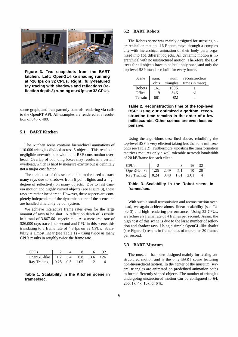
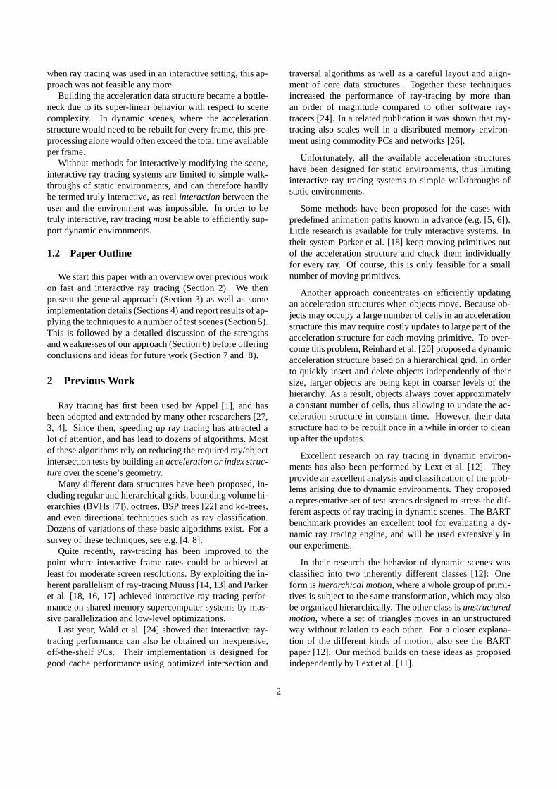
Figure 3. Two snapshots from the BARTkitchen. Left: OpenGL-like shading runningat >26 fps on 32 CPUs. Right: fully-featuredray tracing with shadows and reflections (re-flection depth 3) running at >4 fps on 32 CPUs.
scene graph, and transparently controls rendering via callsto the OpenRT API. All examples are rendered at a resolu-tion of 640 � 480.
5.1 BART Kitchen
The Kitchen scene contains hierarchical animations of110.000 triangles divided across 5 objects. This results innegligible network bandwidth and BSP construction over-head. Overlap of bounding boxes may results in a certainoverhead, which is hard to measure exactly but is definitelynot a major cost factor.
The main cost of this scene is due to the need to tracemany rays due to shadows from 6 point lights and a highdegree of reflectivity on many objects. Due to fast cam-era motion and highly curved objects (see Figure 3), theserays are rather incoherent. However, these aspects are com-pletely independent of the dynamic nature of the scene andare handled efficiently by our system.
We achieve interactive frame rates even for the largeamount of rays to be shot. A reflection depth of 3 resultsin a total of 3.867.661 rays/frame. At a measured rate of526.000 rays traced per second and CPU in this scene, thistranslating to a frame rate of 4.3 fps on 32 CPUs. Scala-bility is almost linear (see Table 1) – using twice as manyCPUs results in roughly twice the frame rate.
CPUs 2 4 8 16 32OpenGL-like 1.7 3.4 6.8 13.6 >26Ray Tracing 0.25 0.5 1.05 2 4
Table 1. Scalability in the Kitchen scene inframes/sec.
5.2 BART Robots
The Robots scene was mainly designed for stressing hi-erarchical animation. 16 Robots move through a complexcity with hierarchical animation of their body parts orga-nized into 161 different objects. All dynamic motion is hi-erarchical with no unstructured motion. Therefore, the BSPtrees for all objects have to be built only once, and only thetop-level BSP must be rebuilt for every frame.
Scene num. num. reconstructionobjs triangles time (in msec)
Robots 161 100K 1Office 9 34K <1Terrain 661 8M 4
Table 2. Reconstruction time of the top-levelBSP: Using our optimized algorithm, recon-struction time remains in the order of a fewmilliseconds. Other scenes are even less ex-pensive.
Using the algorithms described above, rebuilding thetop-level BSP is very efficient taking less than one millisec-ond (see Table 2). Furthermore, updating the transformationmatrices requires only a well tolerable network bandwidthof 20 kB/frame for each client.
CPUs 2 4 8 16 32OpenGL-like 1.25 2.49 5.1 10 20Ray Tracing 0.24 0.48 1.01 2.01 4
Table 3. Scalability in the Robot scene inframes/sec.
With such a small transmission and reconstruction over-head, we again achieve almost-linear scalability (see Ta-ble 3) and high rendering performance. Using 32 CPUs,we achieve a frame rate of 4 frames per second. Again, thehigh cost of this scene is due to the large number of reflec-tion and shadow rays. Using a simple OpenGL-like shader(see Figure 4) results in frame rates of more than 20 framesper second.
5.3 BART Museum
The museum has been designed mainly for testing un-structured motion and is the only BART scene featuringnon-hierarchical motion. In the center of the museum, sev-eral triangles are animated on predefined animation pathsto form differently shaped objects. The number of trianglesundergoing unstructured motion can be configured to 64,256, 1k, 4k, 16k, or 64k.
6

Figure 4. The Bart Robots: 16 robots consist-ing of 161 objects rendered interactively. Leftimage: OpenGL-like shading at >20 fps on 32CPUs. Center image: standard ray tracing(reflection depth of 3) at >4 fps at 32 CPUs.Right image: a color-coded version showingthe different objects.
Even though the complete animation paths are specifiedin the BART scene graph, we do not make use of this in-formation. User controlled movement of the triangles, i.e.without knowledge of future positions, would create thesame results.
As can be expected, unstructured motion becomes costlyfor many triangles. Building the BSP tree for the complexversion of 64k triangles already requires more than one sec-ond (see Table 4). Note, however, that our current algo-rithms for building object BSP trees still leaves plenty ofroom for further optimizations.
Furthermore, the reconstruction time is strongly affectedby the distribution of triangles in space: In the beginning ofthe animation, all triangles are equally and almost-randomlydistributed. This is the worst case for BSPs, which are bestat handling highly uneven distributions, and construction isconsequently costly. During the animation, the triangles or-ganize themselves to form a single surface. This results inmuch faster reconstruction time. The numbers given in Ta-ble 4 are taken at the beginning of the animation, and arethus worst-case results.
Apart from raw reconstruction cost, significant networkbandwidth is required for sending all triangles to everyclient for every frame. Since we use reliable unicast fornetwork transport, 4096 triangles and 16 clients (32 CPUs),resulting roughly 6.5 MB have to be transferred (Table 4).Though this does not yet saturate the network, the perfor-mance of the server is already affected. Consequently, wedo not scale completely linearly any more (see Table 6).
This scene also requires the computation of shadowsfrom two point lights as well as large amounts of reflectionrays. All of the moving triangles are reflective and inco-herently sample the whole environment (see Figure 5). Asthe dynamic behavior of a scene is completely transparentto the shaders, integrating all these effects does not require
num. reconstruction data sent/clienttriangles time (in msec) (in bytes)
museum3 64 1 6,4kmuseum4 256 2 25,6kmuseum5 1k 8 102kmuseum6 4k 34 409kmuseum7 16k 101 1,6Mmuseum8 64k >1s 6,5M
Table 4. Unstructured motion in different con-figurations of the museum scene. The num-ber of triangles only specifies the number oftriangles undergoing unstructured motion.
any additional effort except for the cost for tracing the rays.Even with all these effects – unstructured motion, shad-
ows, and highly incoherent reflections on moving objects –the museum can be rendered interactively: Using 8 clients,we achieve 4.8 fps for 1024 triangles, and still 4.2 fps for4096 triangles in video resolution. Again, the frame rate isdominated by the cost for shadows and reflections. Using anOpenGL-like shader without these effects allows to renderthe scene at 19 frames per second on 8 clients.
Figure 5. Unstructured motion in the BARTmuseum: Up to 64.000 triangles are movingincoherently through the room. Note espe-cially how the entire environment reflects inthese moving triangles (right).
5.4 Outdoor Terrain
The Terrain scene has been specifically designed to testthe scalability with a large number of instances and trian-gles. It contains up to 661 instances of 2 different trees,which corresponds to roughly 10 million triangles after in-stantiation. A point light source creates highly detailedshadows from the leaves (see Figure 6). All trees can bemoved around interactively, both in groups or individually.
The large number of instances results in constructiontimes for the top-level BSP of up to 4 msec per frame. This
7

cost — together with the transmission cost for updating all661 instance matrices on all clients — limits the scalabilityfor a large number of instances and clients (see Table 6).
6 Discussion
The above scenes stress our dynamic ray tracing systemin different areas. Together with the terrain experiment, ourtest scenes contain a strong variation of parameters, rang-ing from 5 to 661 instances, from a few thousand to severalmillion triangles, from simple shading to lots of shadowsand reflections, and from hierarchical animation to unstruc-tured motion of thousands of triangles (for an overview, seeFigure 6). Taken together, these experiments allow to ana-lyze and evaluate our method with respect to many differentaspects.
Transformation Cost The core idea of our method wasto avoid rebuilding the complete data structure, but rathertransform the rays to the coordinate system of each objectwhenever possible. This implies that every ray intersectinga object has to be transformed to that objects local coordi-nate system via matrix-vector multiplications for both rayorigin and direction, resulting in several matrix operationsper ray. As our system shoots approximately half a mil-lion rays per second on an AthlonMP 1800+ CPU, this canamount to hundreds of thousands of matrix-vector multipli-cations per frame (see Table 5). Furthermore, more trans-formations are often required during shading, e.g. by trans-forming the shading normal or for calculating proceduralnoise in the local coordinate system.
Office Terrain Robotsobjects 9 661 161
matrix ops 480K 1600K 1000K
Table 5. Number of the matrix-vector multi-plies for the scenes in our benchmark scenes(resolution 640x480). Note, a matrix opera-tion can be performed in only 23 cycles evenin plain C code, which is negligible comparedto traversal cost.
However the cost for these transformation is rather lowin practice. Even for a straight-forward C-code implemen-tation, a matrix-vector operation costs only 23 cycles on anAMD Athlon MP CPU, which is almost negligible com-pared to the cost for tracing a ray, which is in the order ofseveral hundred to a thousand cycles. The cost for matrixoperations could be further reduced by replacing the matrix-vector multiplications by SSE code [9].
Unstructured Motion As could be expected, the Mu-seum scene has shown that unstructured motion remainscostly for ray tracing. A moderate number of a few thou-sand independently moving triangles can be supported, butlarger numbers would lead to intolerable reconstructiontimes for the respective objects (see Table 4). As such, ourmethod is still not suitable for scenes with strong unstruc-tured motion.
To support such scenes, algorithms for faster reconstruc-tion of dynamic objects have to be developed. Note thatour method could also be combined with Reinhards ap-proach [20] by using his method only for the unstructuredobjects. Even then, lots of unstructured motion would stillcreate a performance problem due to the need to send alltriangle updates to the clients. This is not a limitation ofour specific method, but would be similar for any kind ofalgorithm in a distributed environment.
Bounding Volume Overlap One of the stress cases de-fined in [12] was Bounding Volume Overlap. In fact, thisresults in some form of overhead, as it limits early ray ter-mination. All instances must be tested sequentially in theoverlap area as a valid intersection computed in the first ob-ject might not be visible due to being occluded by anotherinstance.
Though it would be easy to construct scenarios wherethis would lead to excessive overhead, this is rarely signifi-cant in practice. Bounding volume overlap does happens inall our test cases, but has not proven a major performanceproblem. In fact, overlapping objects are identical to usingbounding volume hierarchies (BVHs) [7] as an accelerationstructure, which have proven to work well in practice.
Over-Estimation of Object Bounds Building the top-level BSP requires an estimate of the bounding box of eachinstance in world coordinates. As transforming each indi-vidual vertex would be too costly, we conservatively esti-mate this bounds based on the transformed bounding box ofthe original object.
This sometimes over-estimates the correct bounds andresults in some overhead: During top-level BSP traversal, aray may be intersected with an object that it would not haveintersected otherwise. However, this overhead is restrictedto only transforming and clipping the ray: After transfor-mation to the local coordinate system, such a ray is firstclipped against the correct bounding box, and can thus beimmediately discarded without further traversal.
Teapot-in-a-Stadium Problem The teapot-in-a-stadiumproblem is handled very well by out method: BSP treesadapt automatically to varying object density in a scene [8],which solves the problem for both objects and top-level
8

BSP. In fact, our method even allows to increase perfor-mance for these cases: If the ’teapot’ is contained in a sepa-rate object, the shape of the ’stadium’ BSP is usually muchbetter: The teapot object is already enclosed in tightly fit-ting bounds, without using several additional BSP levels totightly enclose the teapot.
Scalability with the number of Instances Apart fromunstructured motion, the main cost of our method resultsfrom the need to recompute the top-level BSP tree. As such,a large number of instances becomes expensive, as can beseen in the Terrain scene. Still, even the thousand complexinstances can be rendered interactively, and using only a fewdozen instances has negligible impact.
As such, the number of instances should be minimizedin order to achieve optimal performance. It is generallymuch faster to use a few, large objects instead of manysmall ones. All static triangles in a scene should best bestored in a single object, instead of using multiple objects.This is completely different to OpenGLs approach of usingmany, small display lists, and still requires some amount ofmanual porting and optimization when porting applicationsfrom OpenGL to OpenRT.
On the other hand, supporting instantiation (i.e. using ex-actly the same object multiple times in the same frame) isa valuable feature of our method, as this allows to rendercomplex environments very efficiently: With instantiation,memory is required for storing only the two original treesand the top-level BSP, allowing to render even that manytriangles with a small memory footprint. For OpenGL ren-dering, all triangles would still be handled individually bythe graphics hardware even when using display lists.
Scalability in Distributed Environments As could beseen by the experiments in Section 5, we achieve rathergood scalability even for many clients except for scenes thatrequire to update a lot of information on all clients, i.e. fora high degree of unstructured motion (where every movingtriangle must be transmitted), and for a large number of in-stances.
In the terrain scene, using 16 clients would require tosend 676 KB2 per frame simply for updating the 661 trans-formation matrices on the clients. Though this data can besent in a compressed form, load balancing and client/servercommunication further adds to the network bandwidth.Without broadcast/multicast functionality on the network,the server bandwidth increases linearly with the number ofclients. For many clients and lots of updated data, this cre-ates a bandwidth bottleneck on the server, and severely lim-its the scalability (see Table 6).
2661 instances � 16 clients � (4 � 4) floats
In principle, the same is true for unstructured motion,where sending several thousand triangles to each client alsocreates a network bottleneck. On the other hand, both prob-lems are not specific to our method, but apply for any kindof distributed rendering.
OpenGL-like 1 2 4 8 16Robots 1.25 2.49 5.1 10 20Kitchen 1.7 3.4 6.8 13.6 26(-)Terrain 0.68 1.34 2.55 4.76 8.33Museum/1k 2.7 5.4 10.2 19.5 26(-)Museum/4k 2.5 4.5 7.5 4.5 2.5Museum/16k 1.6 2.4 1.7 1 0.5
Ray Tracing 1 2 4 8 16Robots 0.24 0.48 1.01 2.01 4Terrain 0.3 0.6 1.19 2.29 4.26Kitchen 0.25 0.5 1.05 2 4Museum/1k 0.6 1.2 2.4 4.8 9.3Museum/4k 0.55 1.1 2.2 4.2 2.5Museum/16k 0.45 0.9 1.65 0.98 0.53
Table 6. Scalability of our method in thedifferent test scenes. ’-’ means that theservers network connection is completelysaturated, and thus no higher performancecan be achieved. The numbers in the uppertable correspond to pure OpenGL like shad-ing, the lower one is for full ray tracing includ-ing shadows and reflections.
Total Overhead In order to estimate the total overheadof our method, we have compared several scenes in botha static and dynamic configuration. As there are no staticequivalents for the BART benchmarks, we have taken sev-eral of our static test scenes, and have modified them in away that they can be rendered in both a static configura-tion with all triangles in a single, static BSP tree, and ina dynamic configuration, where triangles are grouped intodifferent objects that can then be moved dynamically.
Note, however, that the total performance is affected byseveral factors. Even though transformation and reconstruc-tion cost lead to overhead, using a hierarchy can also havepositive side effects. For example, having small and compli-cated objects (e.g. teapots in a stadium) contained in sep-arate objects can lead to BSP trees that are actually bettersituated than those for a single static BSP tree, and can evenresult in faster traversal.
9

For the scenes that are available in both static and dy-namic configurations, we find that our method creates anoverhead of only 10 to 20 percent for typical scenes. Weconsider this overhead tolerable for the added flexibilitygained through supporting dynamic scenes.
7 Conclusions
We have presented a simple and practical method for in-teractive ray tracing of dynamic scenes. It supports a largevariety of dynamic scenes, including all the BART bench-mark scenes (see Figure 6). It imposes no limitations on thekind of rays to be shot, and as such allows for all the usualray-tracing features like shadows and reflections.
For unstructured motion, our method still incurs a highreconstruction cost per frame, that makes it infeasible for alarge number of incoherently moving triangles. For a mod-erate amount of unstructured motion in the order of a fewthousand moving triangles, however, it is well applicable,and results in frame rates of several frames per second atvideo resolution.
For mostly hierarchical animation — as often applied inscene graphs — our method is highly efficient, and allows tointeractively render even highly complex models with hun-dreds of instances, and millions of triangles per object [23].
With our proposed method, we have been successfullyable to interactively ray trace all the dynamic scenes wehave encountered so far. To our knowledge, this is the firsttime that the BART benchmark suite has been interactivelyray traced at all. Using only an OpenGL like shading modeland a small cluster of commodity PCs, more than 15 to 20frames per second can be achieved in most scenes.
With the unique advantages of ray tracing — now com-bined with the flexibility to handle dynamic environments— we believe that interactive ray tracing is a significant stepcloser to be a viable alternative to triangle rasterization forfuture interactive 3D graphics.
8 Future Work
Even though rebuilding the top-level BSP has not provento be a major problem, we would be able to organizationobjects into a hierarchy instead of a flat list. This would fur-ther limit the number of objects affected by a local change.As most of the updated data is the same for every client,the support of network broadcast/multicast would be a verysimple solution to the bandwidth problem, as the transmis-sion time would not be affected by the number of clients.
In order to avoid the scalability bottleneck due to trans-mission cost on the network and BSP construction cost onall clients, future work will investigate algorithms for lazyloading of the geometry and for lazy construction of the
BSP trees. Unstructured motion could be improved by de-signing specialized algorithms for cases where motion isspatially limited in some form, such as for skinning.
We are also investigating how existing applications canbe mapped to our method, e.g. by evaluating how a scenegraph library such as OpenInventor or VRML can be effi-ciently implemented on top of our system.
References
[1] A. Appel. Some Techniques for Shading Machine Renderings ofSolids. SJCC, pages 27–45, 1968.
[2] OpenGL Architecture Review Board. OpenGL Reference Manual:The Official Reference Document for OpenGL, Release 1, 1993.
[3] Robert Cook, Thomas Porter, and Loren Carpenter. Distributed raytracing. In ACM SIGGRAPH Computer Graphics, volume 18, pages137–144, 1984.
[4] Andrew Glassner. An Introduction to Raytracing. Academic Press,1989.
[5] Andrew S. Glassner. Spacetime ray tracing for animation. IEEEComputer Graphics and Applications, 8(2):60–70, 1988.
[6] Eduard Gröller and Werner Purgathofer. Using temporal and spatialcoherence for accelerating the calculation of animation sequences.In Proceedings of EUROGRAPHICSt’91, pages 103–113. ElsevierScience Publishers, 1991.
[7] Eric Haines. Efficiency improvements for hierarchy traversal in raytracing. In James Arvo, editor, Graphics Gems II, pages 267–272.Academic Press, 1991.
[8] Vlastimil Havran. Heuristic Ray Shooting Algorithms. PhD thesis,Czech Technical University, 2001.
[9] Intel Corp. Intel Pentium III Streaming SIMD Extensions.http://developer.intel.com/vtune/cbts/simd.htm.
[10] David Kirk and James Arvo. Improved ray tragging for voxel-basedray tracing. Graphics Gems II, 1991.
[11] Jonas Lext and Tomas Akenine-Möller. Towards rapid reconstruc-tion for animated ray tracing. In Eurographics 2001 – Short Presen-tations, pages pp. 311–318, 2001.
[12] Jonas Lext, Ulf Assarsson, and Tomas Moeller. BART: A benchmarkfor animated ray tracing. Technical report, Department of ComputerEngineering, Chalmers University of Technology, Goeteborg, Swe-den, May 2000. Available at http://www.ce.chalmers.se/BART/.
[13] Michael J. Muuss. Towards real-time ray-tracing of combinatorialsolid geometric models. In Proceedings of BRL-CAD Symposium’95, June 1995.
[14] Michael J. Muuss and Maximo Lorenzo. High-resolution interactivemultispectral missile sensor simulation for atr and dis. In Proceed-ings of BRL-CAD Symposium ’95, June 1995.
[15] Jackie Neider, Tom Davis, and Mason Woo. OpenGL ProgrammingGuide. Addison-Wesley, Reading MA, 1993.
[16] Steven Parker, Michael Parker, Yaren Livnat, Peter Pike Sloan,Chuck Hansen, and Peter Shirley. Interactive ray tracing for vol-ume visualization. IEEE Transactions on Computer Graphics andVisualization, 5(3):238–250, July-September 1999.
[17] Steven Parker, Peter Shirley, Yarden Livnat, Charles Hansen, andPeter Pike Sloan. Interactive ray tracing for isosurface rendering. InIEEE Visualization ’98, pages 233–238, October 1998.
[18] Steven Parker, Peter Shirley, Yarden Livnat, Charles Hansen, and Pe-ter Pike Sloan. Interactive Ray Tracing. In Symposium on Interactive3D Graphics, pages 119–126. ACM SIGGRAPH, 1999.
10

[19] Timothy John Purcell, Ian Buck, William R. Mark, and Pat Hanra-han. Ray tracing on programmable graphics hardware. In Proceed-ings of SIGGRAPH, 2002. (to appear).
[20] Erik Reinhard, Brian Smits, and Chuck Hansen. Dynamic accelera-tion structures for interactive ray tracing. In Proceedings Eurograph-ics Workshop on Rendering, pages 299–306, Brno, Czech Republic,June 2000.
[21] Joerg Schmittler, Ingo Wald, and Philipp Slusallek. SaarCOR – AHardware Architecture for Realtime Ray-Tracing. submitted for pub-lication, also available as a technical report, http://graphics.cs.uni-sb.de/Publications, 2002.
[22] K. Sung and P. Shirley. Ray Tracing with the BSP-tree. In D. Kirk,editor, Graphics Gems III, pages 271–274. Academic Press, 1992.
[23] Ingo Wald, Carsten Benthin, and Philipp Slusallek. OpenRT - aFlexible and Scalable Rendering Engine for Interactive 3D Graph-ics. submitted for publication, also available as a technical report,http://graphics.cs.uni-sb.de/Publications, 2002.
[24] Ingo Wald, Carsten Benthin, Markus Wagner, and Philipp Slusallek.Interactive rendering with coherent ray tracing. Computer GraphicsForum, 20(3), 2001.
[25] Ingo Wald, Thomas Kollig, Carsten Benthin, Alexander Keller, andPhilipp Slusallek. Interactive Global Illumination. submitted for pub-lication, also available as a technical report, http://graphics.cs.uni-sb.de/Publications, 2002.
[26] Ingo Wald, Philipp Slusallek, and Carsten Benthin. Interactive dis-tributed ray tracing of highly complex models. In Proceedings of the12th EUROGRPAHICS Workshop on Rendering, June 2001. London.
[27] T. Whitted. An improved illumination model for shaded display.CACM, 23(6):343–349, June 1980.
11

Figure 6. Some example frames from several dynamic scenes. From top to bottom: The BART robotsscene contains roughly 100.000 triangles in 161 moving objects. Below that, is the BART kitchenscene. The museum scene contains unstructured motion of several thousand triangles. Note howthe entire museum reflects in these triangles. The terrain viewer application uses up to 661 instancesof 2 trees, would contain several million triangles without instantiation, and even calculates shadows.The office scene is a practical application from interactive lighting simulation, and demonstrates thatthe method works fully automatically and completely transparently to the shader.
12