A short-range UWBFM transceiver for 5 - hamradio.silea.hamradio.si/~s53mv/nbp/ax25/Uwbfm5.pdfA...
9
A short-range UWBFM transceiver for 5.8GHz Matjaž Vidmar A simple, short-range UWBFM transceiver operating in the 5.8GHz frequency band is described in this article. The transceiver is intended for initial tests of 10Mbps packet-radio equipment. The block diagram includes a common frequency synthesizer used both as a simple FM transmitter and as a local oscillator for the receiver: The same HEMT is used as the TX output stage providing some 35mW of power at 5.8GHz during transmission and as a passive mixer with a pretty good noise figure during reception. The IF frequency is centered around 144MHz with a bandwidth of about 40MHz. Of course a communicating pair of such transceivers transmits on two different frequencies spaced by the IF value, in this case 5664MHz and 5808MHz:
Transcript of A short-range UWBFM transceiver for 5 - hamradio.silea.hamradio.si/~s53mv/nbp/ax25/Uwbfm5.pdfA...

A short-range UWBFM transceiver for 5.8GHz
Matjaž Vidmar
A simple, short-range UWBFM transceiver operating in the 5.8GHz frequency band is described in this article. The transceiver is intended for initial tests of 10Mbps packet-radio equipment. The block diagram includes a common frequency synthesizer used both as a simple FM transmitter and as a local oscillator for the receiver:
The same HEMT is used as the TX output stage providing some 35mW of power at 5.8GHz during transmission and as a passive mixer with a pretty good noise figure during reception. The IF frequency is centered around 144MHz with a bandwidth of about 40MHz. Of course a communicating pair of such transceivers transmits on two different frequencies spaced by the IF value, in this case 5664MHz and 5808MHz:

The microwave part of the synthesizer includes a VCO operating around 2.9GHz and a frequency doubler to 5.8GHz:

The digital part of the synthesizer includes a μPB1505 prescaler and a MC145106 PLL chip supporting frequency steps of 24MHz selected by solder jumpers on the PCB:
The RF front end includes a single HEMT MGF4918D. During transmission the HEMT operates as an amplifier with conventional DC drain bias. During reception the drain is not biased so that the HEMT operates as a passive mixer. An INA-03184 MMIC is used as the IF preamplifier. A bias network is provided to supply additional amplifiers through the antenna connector:

The INA-03184 is followed by three INA-52063 amplifiers in the IF chain. Two INA-52063 amplifiers are located in the IF amplifier module:

The third INA-52063 amplifier is connected to a FM demodulator built around an IAM-81008 analog multiplier. The output of the FM demodulator is limited and converted to TTL levels using 74HC02 logical gates. The demodulator module also includes the modulator driver 74HC125 and the RX/TX supply switch logic:


Both microwave boards are microstrip circuits (25mmX80mm and 20mmX80mm) built on 0.5mm (19mils) thick Ultralam 2000 teflon laminate. The remaining boards (twice 20mmX80mm and 40mmX100mm) are single-sided FR4:
Except for the demodulator board all remaining modules require shielding. The frequency synthesizer is installed in one brass frame while the RF front end and IF amplifier are installed in another brass frame. The geometry of all brass frames is selected to keep any internal resonances high enough to avoid any need for microwave absorbers:

Both brass frames are then covered by brass covers for shielding purposes:
For short-range testing a pair of radios may be equipped with simple ground-plane antennas. Even some attenuators may be required at a few meter distance like testing inside a room:
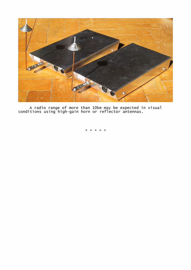
A radio range of more than 10km may be expected in visual conditions using high-gain horn or reflector antennas.
* * * * *