A short, off-center fed dipole for 40 m and 20 m by Daniel ... · A short, off-center fed dipole...
11
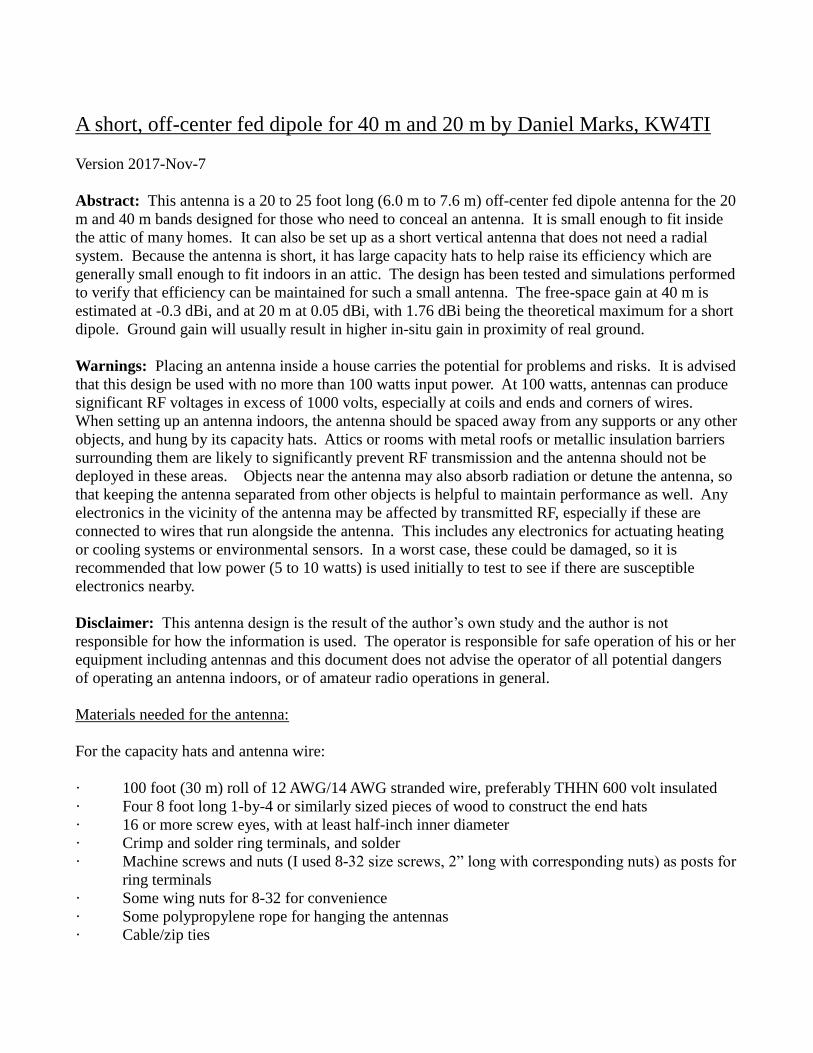
A short, off-center fed dipole for 40 m and 20 m by Daniel Marks, KW4TI Version 2017-Nov-7 Abstract: This antenna is a 20 to 25 foot long (6.0 m to 7.6 m) off-center fed dipole antenna for the 20 m and 40 m bands designed for those who need to conceal an antenna. It is small enough to fit inside the attic of many homes. It can also be set up as a short vertical antenna that does not need a radial system. Because the antenna is short, it has large capacity hats to help raise its efficiency which are generally small enough to fit indoors in an attic. The design has been tested and simulations performed to verify that efficiency can be maintained for such a small antenna. The free-space gain at 40 m is estimated at -0.3 dBi, and at 20 m at 0.05 dBi, with 1.76 dBi being the theoretical maximum for a short dipole. Ground gain will usually result in higher in-situ gain in proximity of real ground. Warnings: Placing an antenna inside a house carries the potential for problems and risks. It is advised that this design be used with no more than 100 watts input power. At 100 watts, antennas can produce significant RF voltages in excess of 1000 volts, especially at coils and ends and corners of wires. When setting up an antenna indoors, the antenna should be spaced away from any supports or any other objects, and hung by its capacity hats. Attics or rooms with metal roofs or metallic insulation barriers surrounding them are likely to significantly prevent RF transmission and the antenna should not be deployed in these areas. Objects near the antenna may also absorb radiation or detune the antenna, so that keeping the antenna separated from other objects is helpful to maintain performance as well. Any electronics in the vicinity of the antenna may be affected by transmitted RF, especially if these are connected to wires that run alongside the antenna. This includes any electronics for actuating heating or cooling systems or environmental sensors. In a worst case, these could be damaged, so it is recommended that low power (5 to 10 watts) is used initially to test to see if there are susceptible electronics nearby. Disclaimer: This antenna design is the result of the author’s own study and the author is not responsible for how the information is used. The operator is responsible for safe operation of his or her equipment including antennas and this document does not advise the operator of all potential dangers of operating an antenna indoors, or of amateur radio operations in general. Materials needed for the antenna: For the capacity hats and antenna wire: · 100 foot (30 m) roll of 12 AWG/14 AWG stranded wire, preferably THHN 600 volt insulated · Four 8 foot long 1-by-4 or similarly sized pieces of wood to construct the end hats · 16 or more screw eyes, with at least half-inch inner diameter · Crimp and solder ring terminals, and solder · Machine screws and nuts (I used 8-32 size screws, 2” long with corresponding nuts) as posts for ring terminals · Some wing nuts for 8-32 for convenience · Some polypropylene rope for hanging the antennas · Cable/zip ties
Transcript of A short, off-center fed dipole for 40 m and 20 m by Daniel ... · A short, off-center fed dipole...
A short, off-center fed dipole for 40 m and 20 m by Daniel Marks, KW4TI
Version 2017-Nov-7
Abstract: This antenna is a 20 to 25 foot long (6.0 m to 7.6 m) off-center fed dipole antenna for the 20
m and 40 m bands designed for those who need to conceal an antenna. It is small enough to fit inside
the attic of many homes. It can also be set up as a short vertical antenna that does not need a radial
system. Because the antenna is short, it has large capacity hats to help raise its efficiency which are
generally small enough to fit indoors in an attic. The design has been tested and simulations performed
to verify that efficiency can be maintained for such a small antenna. The free-space gain at 40 m is
estimated at -0.3 dBi, and at 20 m at 0.05 dBi, with 1.76 dBi being the theoretical maximum for a short
dipole. Ground gain will usually result in higher in-situ gain in proximity of real ground.
Warnings: Placing an antenna inside a house carries the potential for problems and risks. It is advised
that this design be used with no more than 100 watts input power. At 100 watts, antennas can produce
significant RF voltages in excess of 1000 volts, especially at coils and ends and corners of wires.
When setting up an antenna indoors, the antenna should be spaced away from any supports or any other
objects, and hung by its capacity hats. Attics or rooms with metal roofs or metallic insulation barriers
surrounding them are likely to significantly prevent RF transmission and the antenna should not be
deployed in these areas. Objects near the antenna may also absorb radiation or detune the antenna, so
that keeping the antenna separated from other objects is helpful to maintain performance as well. Any
electronics in the vicinity of the antenna may be affected by transmitted RF, especially if these are
connected to wires that run alongside the antenna. This includes any electronics for actuating heating
or cooling systems or environmental sensors. In a worst case, these could be damaged, so it is
recommended that low power (5 to 10 watts) is used initially to test to see if there are susceptible
electronics nearby.
Disclaimer: This antenna design is the result of the author’s own study and the author is not
responsible for how the information is used. The operator is responsible for safe operation of his or her
equipment including antennas and this document does not advise the operator of all potential dangers
of operating an antenna indoors, or of amateur radio operations in general.
Materials needed for the antenna:
For the capacity hats and antenna wire:
· 100 foot (30 m) roll of 12 AWG/14 AWG stranded wire, preferably THHN 600 volt insulated
· Four 8 foot long 1-by-4 or similarly sized pieces of wood to construct the end hats
· 16 or more screw eyes, with at least half-inch inner diameter
· Crimp and solder ring terminals, and solder
· Machine screws and nuts (I used 8-32 size screws, 2” long with corresponding nuts) as posts for
ring terminals
· Some wing nuts for 8-32 for convenience
· Some polypropylene rope for hanging the antennas
· Cable/zip ties

For the loading coils:
· A short length of 2” PVC and 1.5” PVC pipe
· Caterpillar grommet / edging grommet 2 mm to 2.54 mm (1/10 inch) spacing
· Some adhesive to glue (e.g. hot glue or epoxy) to glue the grommet onto the PVC pipe
· 4 or 5 m length of magnet wire (14 to 18 AWG)
For the balun:
· 1 m long RG-316 coaxial cable, solid copper or silver plated copper center conductor strongly
preferred over copper-clad steel
· Two FT240-43, 2.4” diameter 43-mix ferrite cores
· SO-239 UHF panel connector (silver plated preferred for easy soldering)
· 14-18 AWG insulated wire, THHN or Teflon insulated
· A small sheet of plexiglas/lucite or PVC to mount the balun and feedpoint.
· Heat shrink tubing
An antenna analyzer is extremely helpful, almost necessary, to avoid headaches of deployment.
The diagram of the antenna is above. It consists of two capacity hats at either end of the antenna which
are 1 meter by 1 meter squares. There are crosses in the middle of each capacity hat that attach to a
central attachment point. Each has a 0.5 m length of wire connecting it to its corresponding loading
coil. One side of the antenna (in the diagram the left side), resonates at the 20 m band, while the other
resonates at the 40 m band. The antenna is fed off-center so that the feed impedance may be matched
at 50 ohms. The two sides of the antenna attach to a feedpoint at which a balun is placed. This balun
is extremely important to the design and should not be omitted, and is best constructed to the
specifications given in this document. It is specifically designed to work with this antenna. The balun
prevents feed line radiation as well as noise pickup, provides consistent matching to the antenna, and
enables the two sides of the antenna to work with each other to realize a dipole.

The capacity hats are large so that the current is uniform over the length of the antenna wire in the 40 m
band. This is what enables this short antenna (25 feet long) to have an efficiency a significant fraction
of a half-wave dipole antenna (66 feet long). They are constructed as shown above. An “H” shape is
made with three 4 foot long (1.2 m long) wooden boards, and four screws are inserted into the board in
a square to make a 1 meter square. A loop of copper wire is threaded around the four screws to make a
square loop, with the ends of the loop soldered together. In the middle of the sides of the square, the
insulation is stripped away using a razor blade, and two more wires are soldered across the sides of the
square. These two wires are stripped and soldered together in the center and to a short wire with a ring
terminal on the end. A hole is drilled through the center of the capacity hat and a screw is inserted
through the back of the capacity hat to act as a post for the ring terminals. A screw eye on the front
acts as an anchor point for a strain relief rope so that the rope does not allow the antenna wire to
become taut. Four screw eyes are mounted on the back of the capacity hat so that the hat may be hung
up by ropes.
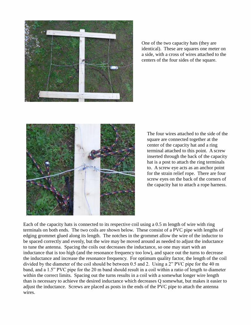
One of the two capacity hats (they are
identical). These are squares one meter on
a side, with a cross of wires attached to the
centers of the four sides of the square.
The four wires attached to the side of the
square are connected together at the
center of the capacity hat and a ring
terminal attached to this point. A screw
inserted through the back of the capacity
hat is a post to attach the ring terminals
to. A screw eye acts as an anchor point
for the strain relief rope. There are four
screw eyes on the back of the corners of
the capacity hat to attach a rope harness.
Each of the capacity hats is connected to its respective coil using a 0.5 m length of wire with ring
terminals on both ends. The two coils are shown below. These consist of a PVC pipe with lengths of
edging grommet glued along its length. The notches in the grommet allow the wire of the inductor to
be spaced correctly and evenly, but the wire may be moved around as needed to adjust the inductance
to tune the antenna. Spacing the coils out decreases the inductance, so one may start with an
inductance that is too high (and the resonance frequency too low), and space out the turns to decrease
the inductance and increase the resonance frequency. For optimum quality factor, the length of the coil
divided by the diameter of the coil should be between 0.5 and 2. Using a 2” PVC pipe for the 40 m
band, and a 1.5” PVC pipe for the 20 m band should result in a coil within a ratio of length to diameter
within the correct limits. Spacing out the turns results in a coil with a somewhat longer wire length
than is necessary to achieve the desired inductance which decreases Q somewhat, but makes it easier to
adjust the inductance. Screws are placed as posts in the ends of the PVC pipe to attach the antenna
wires.
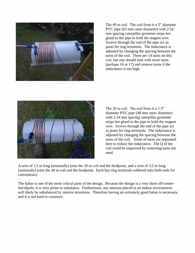
The 40 m coil. The coil form is a 2” diameter
PVC pipe (63 mm outer diameter) with 2.54
mm spacing caterpillar grommet strips hot
glued to the pipe to hold the magnet wire.
Screws through the end of the pipe act as
posts for ring terminals. The inductance is
adjusted by changing the spacing between the
turns of the coil. There are 14 turns on this
coil, but one should start with more turns
(perhaps 16 or 17) and remove turns if the
inductance is too high.
The 20 m coil. The coil form is a 1.5”
diameter PVC pipe (48 mm outer diameter)
with 2.54 mm spacing caterpillar grommet
strips hot glued to the pipe to hold the magnet
wire. Screws through the end of the pipe act
as posts for ring terminals. The inductance is
adjusted by changing the spacing between the
turns of the coil. Some of turns are separated
here to reduce the inductance. The Q of the
coil could be improved by removing turns not
used.
A wire of 1.5 m long (nominally) joins the 20 m coil and the feedpoint, and a wire of 3.5 m long
(nominally) joins the 40 m coil and the feedpoint. Each has ring terminals soldered onto both ends for
convenience.
The balun is one of the most critical parts of the design. Because the design is a very short off-center-
fed-dipole, it is very prone to unbalance. Furthermore, any antenna placed in an indoor environment
will likely be unbalanced by interior structures. Therefore having an extremely good balun is necessary,
and it is not hard to construct.
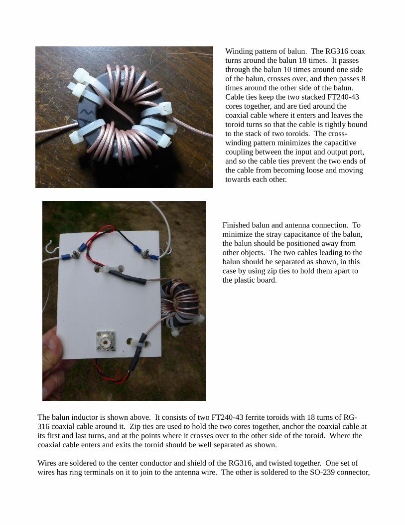
Winding pattern of balun. The RG316 coax
turns around the balun 18 times. It passes
through the balun 10 times around one side
of the balun, crosses over, and then passes 8
times around the other side of the balun.
Cable ties keep the two stacked FT240-43
cores together, and are tied around the
coaxial cable where it enters and leaves the
toroid turns so that the cable is tightly bound
to the stack of two toroids. The cross-
winding pattern minimizes the capacitive
coupling between the input and output port,
and so the cable ties prevent the two ends of
the cable from becoming loose and moving
towards each other.
Finished balun and antenna connection. To
minimize the stray capacitance of the balun,
the balun should be positioned away from
other objects. The two cables leading to the
balun should be separated as shown, in this
case by using zip ties to hold them apart to
the plastic board.
The balun inductor is shown above. It consists of two FT240-43 ferrite toroids with 18 turns of RG-
316 coaxial cable around it. Zip ties are used to hold the two cores together, anchor the coaxial cable at
its first and last turns, and at the points where it crosses over to the other side of the toroid. Where the
coaxial cable enters and exits the toroid should be well separated as shown.
Wires are soldered to the center conductor and shield of the RG316, and twisted together. One set of
wires has ring terminals on it to join to the antenna wire. The other is soldered to the SO-239 connector,
with the center of the coax joined to the pin of the SO-239, and the shield wire soldered to, for example,
one of the holes in the connector. Heat shrink is used to insulate the connections to the coaxial cable.
For example, with the balun constructed as above with 100 W input power or 1.4 A current, an RF
ammeter measured 0.03 A of common-mode current at the feedpoint in the 40 m band, and 0.04 A of
common-mode current in the 20 m band, so that the balun is achieving its intended purpose of limiting
common-mode current on the coaxial cable shield. These measurements are +/- 0.01 A.
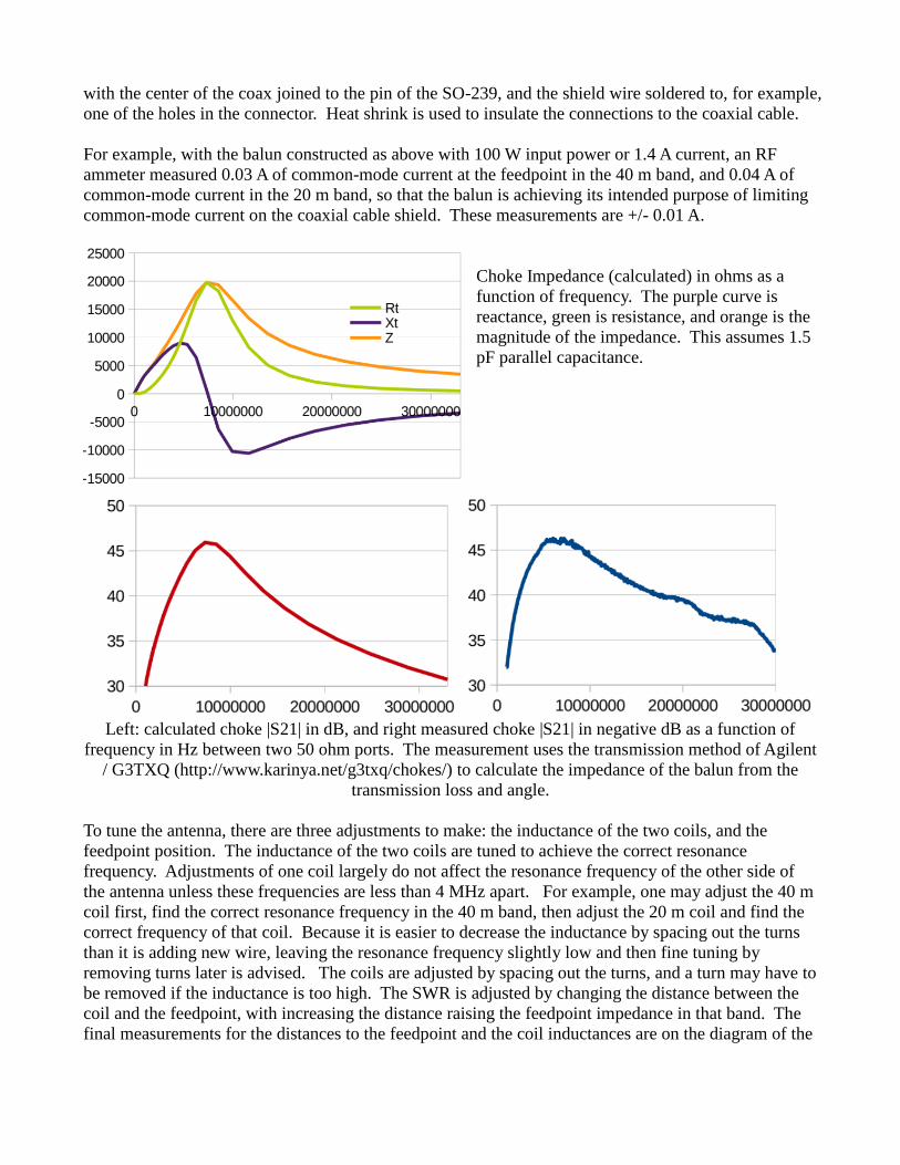
Choke Impedance (calculated) in ohms as a
function of frequency. The purple curve is
reactance, green is resistance, and orange is the
magnitude of the impedance. This assumes 1.5
pF parallel capacitance.
Left: calculated choke |S21| in dB, and right measured choke |S21| in negative dB as a function of
frequency in Hz between two 50 ohm ports. The measurement uses the transmission method of Agilent
/ G3TXQ (http://www.karinya.net/g3txq/chokes/) to calculate the impedance of the balun from the
transmission loss and angle.
To tune the antenna, there are three adjustments to make: the inductance of the two coils, and the
feedpoint position. The inductance of the two coils are tuned to achieve the correct resonance
frequency. Adjustments of one coil largely do not affect the resonance frequency of the other side of
the antenna unless these frequencies are less than 4 MHz apart. For example, one may adjust the 40 m
coil first, find the correct resonance frequency in the 40 m band, then adjust the 20 m coil and find the
correct frequency of that coil. Because it is easier to decrease the inductance by spacing out the turns
than it is adding new wire, leaving the resonance frequency slightly low and then fine tuning by
removing turns later is advised. The coils are adjusted by spacing out the turns, and a turn may have to
be removed if the inductance is too high. The SWR is adjusted by changing the distance between the
coil and the feedpoint, with increasing the distance raising the feedpoint impedance in that band. The
final measurements for the distances to the feedpoint and the coil inductances are on the diagram of the
antenna, however, these will be strongly affected by the environment around the antenna, especially
indoors. An antenna analyzer is almost indispensable to help tune the antenna.
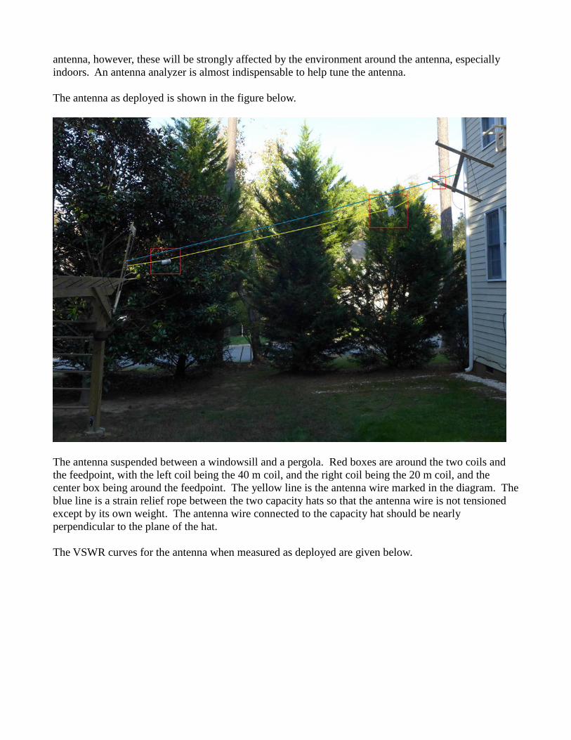
The antenna as deployed is shown in the figure below.
The antenna suspended between a windowsill and a pergola. Red boxes are around the two coils and
the feedpoint, with the left coil being the 40 m coil, and the right coil being the 20 m coil, and the
center box being around the feedpoint. The yellow line is the antenna wire marked in the diagram. The
blue line is a strain relief rope between the two capacity hats so that the antenna wire is not tensioned
except by its own weight. The antenna wire connected to the capacity hat should be nearly
perpendicular to the plane of the hat.
The VSWR curves for the antenna when measured as deployed are given below.

Measured VSWR as a function of
frequency, from 1 MHz to 30 MHz. At
the 10 m band, there is a resonance (zero
reactance point) because the distance
between the two coils is about 5 m, or a
half-wave dipole at 10 m.
Measured VSWR as a function of
frequency at 40 m band
Measured VSWR as a function of
frequency at 20 m band

NEC2 Model CM Off Center Fed Dipole With Capacitive Hats 40m/20m
CM
CE
GW 1 64 0 0 5 0 4 5 0.001 'feed segment
GW 2 64 0 -2 5 0 0 5 0.001 'feed segment
GW 8 64 0 0 5 10 0 5 0.001 'feed wire proxy
GW 100 10 0 4 5 0 4 5.5 0.001 'crosses of cap hat
GW 101 10 0 4 5 0 4 4.5 0.001
GW 102 10 0 4 5 0.5 4 5 0.001
GW 103 10 0 4 5 -0.5 4 5 0.001
GW 104 10 -0.5 4 5.5 0.5 4 5.5 0.001 'crosses of cap hat
GW 105 10 -0.5 4 4.5 0.5 4 4.5 0.001
GW 106 10 0.5 4 4.5 0.5 4 5.5 0.001
GW 107 10 -0.5 4 4.5 -0.5 4 5.5 0.001
GW 400 10 0 -2 5 0 -2 5.5 0.001
GW 401 10 0 -2 5 0 -2 4.5 0.001
GW 402 10 0 -2 5 0.5 -2 5 0.001
GW 403 10 0 -2 5 -0.5 -2 5 0.001
GW 404 10 -0.5 -2 5.5 0.5 -2 5.5 0.001
GW 405 10 -0.5 -2 4.5 0.5 -2 4.5 0.001
GW 406 10 0.5 -2 4.5 0.5 -2 5.5 0.001
GW 407 10 -0.5 -2 5.5 -0.5 -2 4.5 0.001
GE 0
LD 6 1 56 56 200 14.75e-6 1e-12
LD 6 2 16 16 200 4.9e-6 1e-12
LD 1 8 1 1 22100 10992e-6 0.6e-12
GN -1
EK
EX 0 1 1 0 1.0 0 0
FR 0 0 0 0 14.2 0
EN
Example NEC file with parameters measured from balun.
20 m band side of the antenna is 2 m long, 40 m band side of the antenna is 4 m long
40 m band: Radiation Efficiency 60.1%, peak gain -0.3 dBi
Balun losses 16.8%, 40 m coil loss 20.5%, 20 m coil load 2.56%. Q=200 assumed
Balun impedance 19600 || +j505000 ohms
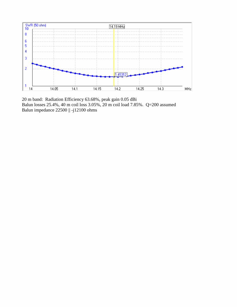
20 m band: Radiation Efficiency 63.68%, peak gain 0.05 dBi
Balun losses 25.4%, 40 m coil loss 3.05%, 20 m coil load 7.85%. Q=200 assumed
Balun impedance 22500 || -j12100 ohms