A series greenhouse - Greenhouses | Composters | …exaco.com/assembly/Tulip_Holland House...
24
A series greenhouse Assembly instructions Walk-in Greenhouse MODEL A (mm) B (mm) C (mm) A705 2098 1518 A707 2234 A710 2950 A712 3666 A714 4382 2183 C B A
Transcript of A series greenhouse - Greenhouses | Composters | …exaco.com/assembly/Tulip_Holland House...
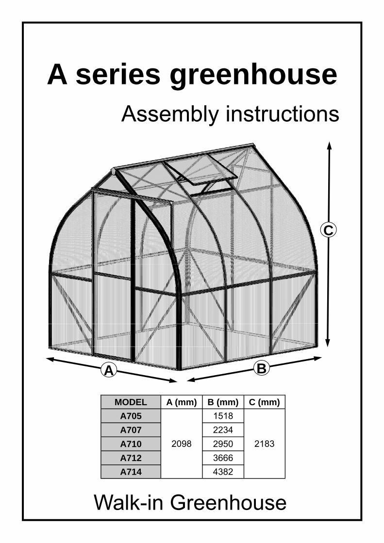
A series greenhouse Assembly instructions
Walk-in Greenhouse
MODEL A (mm) B (mm) C (mm)
A705
2098
1518
A707 2234
A710 2950
A712 3666
A714 4382
2183
C
B
A
2
Statement
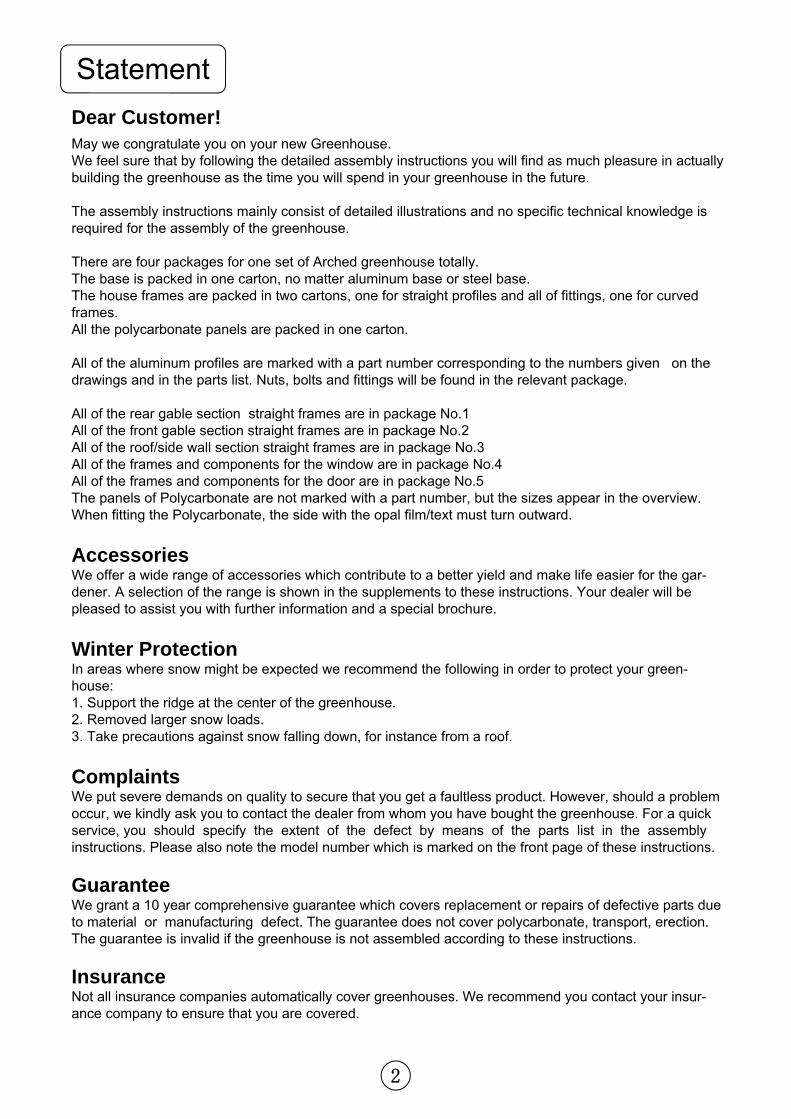
Dear Customer! May we congratulate you on your new Greenhouse. We feel sure that by following the detailed assembly instructions you will find as much pleasure in actually building the greenhouse as the time you will spend in your greenhouse in the future. The assembly instructions mainly consist of detailed illustrations and no specific technical knowledge is required for the assembly of the greenhouse. There are four packages for one set of Arched greenhouse totally. The base is packed in one carton, no matter aluminum base or steel base. The house frames are packed in two cartons, one for straight profiles and all of fittings, one for curved frames. All the polycarbonate panels are packed in one carton. All of the aluminum profiles are marked with a part number corresponding to the numbers given on the drawings and in the parts list. Nuts, bolts and fittings will be found in the relevant package. All of the rear gable section straight frames are in package No.1 All of the front gable section straight frames are in package No.2 All of the roof/side wall section straight frames are in package No.3 All of the frames and components for the window are in package No.4 All of the frames and components for the door are in package No.5 The panels of Polycarbonate are not marked with a part number, but the sizes appear in the overview. When fitting the Polycarbonate, the side with the opal film/text must turn outward.
Accessories We offer a wide range of accessories which contribute to a better yield and make life easier for the gar-dener. A selection of the range is shown in the supplements to these instructions. Your dealer will be pleased to assist you with further information and a special brochure.
Winter Protection In areas where snow might be expected we recommend the following in order to protect your green-house: 1. Support the ridge at the center of the greenhouse. 2. Removed larger snow loads. 3. Take precautions against snow falling down, for instance from a roof.
Complaints We put severe demands on quality to secure that you get a faultless product. However, should a problem occur, we kindly ask you to contact the dealer from whom you have bought the greenhouse. For a quick service, you should specify the extent of the defect by means of the parts list in the assembly instructions. Please also note the model number which is marked on the front page of these instructions.
Guarantee We grant a 10 year comprehensive guarantee which covers replacement or repairs of defective parts due to material or manufacturing defect. The guarantee does not cover polycarbonate, transport, erection. The guarantee is invalid if the greenhouse is not assembled according to these instructions.
Insurance Not all insurance companies automatically cover greenhouses. We recommend you contact your insur-ance company to ensure that you are covered.
3
Statement
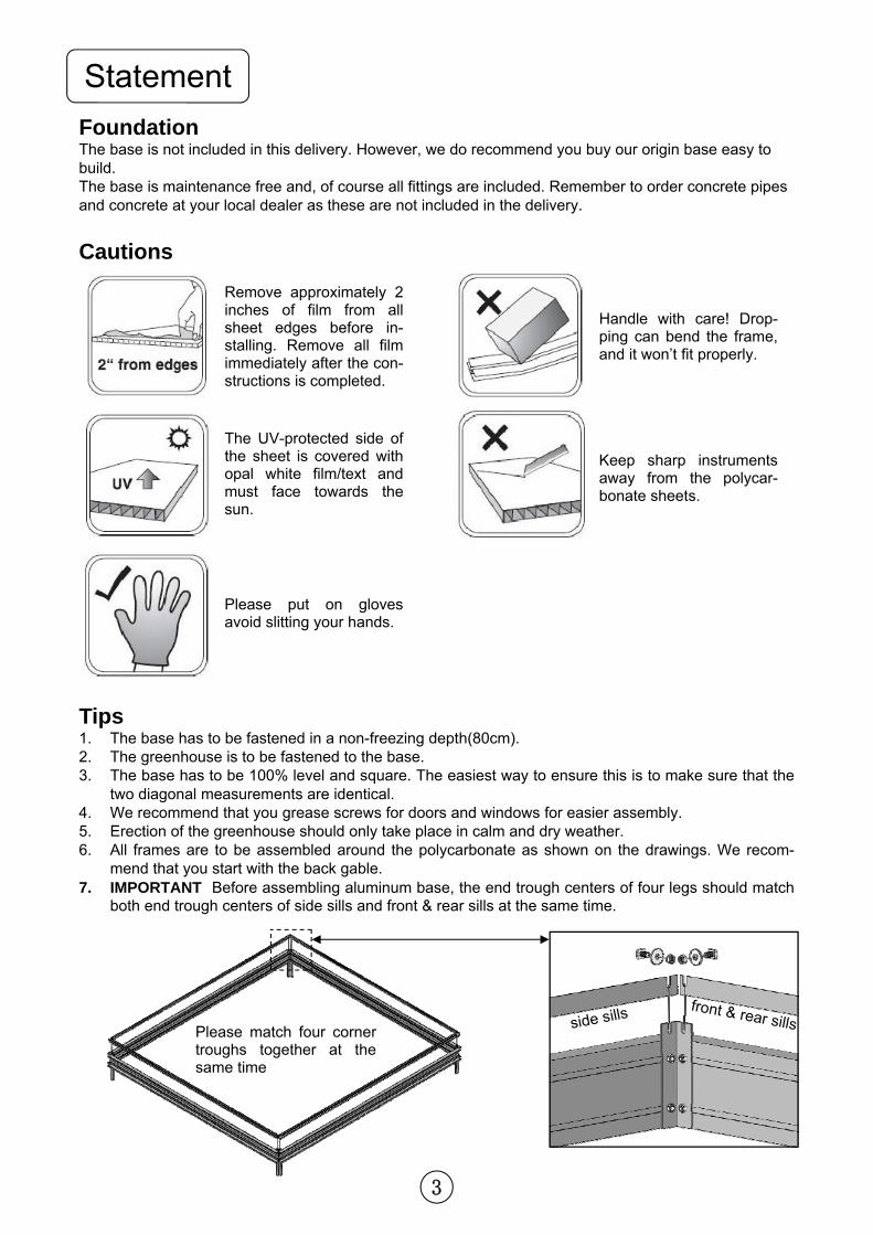
Tips 1. The base has to be fastened in a non-freezing depth(80cm). 2. The greenhouse is to be fastened to the base. 3. The base has to be 100% level and square. The easiest way to ensure this is to make sure that the
two diagonal measurements are identical. 4. We recommend that you grease screws for doors and windows for easier assembly. 5. Erection of the greenhouse should only take place in calm and dry weather. 6. All frames are to be assembled around the polycarbonate as shown on the drawings. We recom-
mend that you start with the back gable. 7. IMPORTANT Before assembling aluminum base, the end trough centers of four legs should match
both end trough centers of side sills and front & rear sills at the same time.
Remove approximately 2 inches of film from all sheet edges before in-stalling. Remove all film immediately after the con-structions is completed.
The UV-protected side of the sheet is covered with opal white film/text and must face towards the sun.
Please put on gloves avoid slitting your hands.
Handle with care! Drop-ping can bend the frame, and it won’t fit properly.
Keep sharp instruments away from the polycar-bonate sheets.
Cautions
Foundation The base is not included in this delivery. However, we do recommend you buy our origin base easy to build. The base is maintenance free and, of course all fittings are included. Remember to order concrete pipes and concrete at your local dealer as these are not included in the delivery.
side sills front & rear sills Please match four corner
troughs together at the same time
4
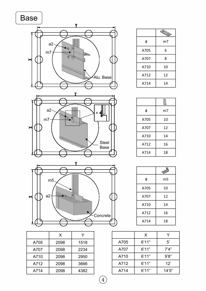
Base
X Y
A705 2098 1518
A707 2098 2234
A710 2098 2950
A712 2098 3666
A714 2098 4382
X Y
A705 6’11” 5’
A707 6’11” 7’4”
A710 6’11” 9’8”
A712 6’11” 12’
A714 6’11” 14’5”
# m7
A705 6
A707 8
A710 10
A712 12
A714 14
# m5
A705 10
A707 12
A710 14
A712 16
A714 18
# m7
A705 10
A707 12
A710 14
A712 16
A714 18
a2
m7
Alu. Base
a2
m5
Concrete
a2
m7
Steel Base
5
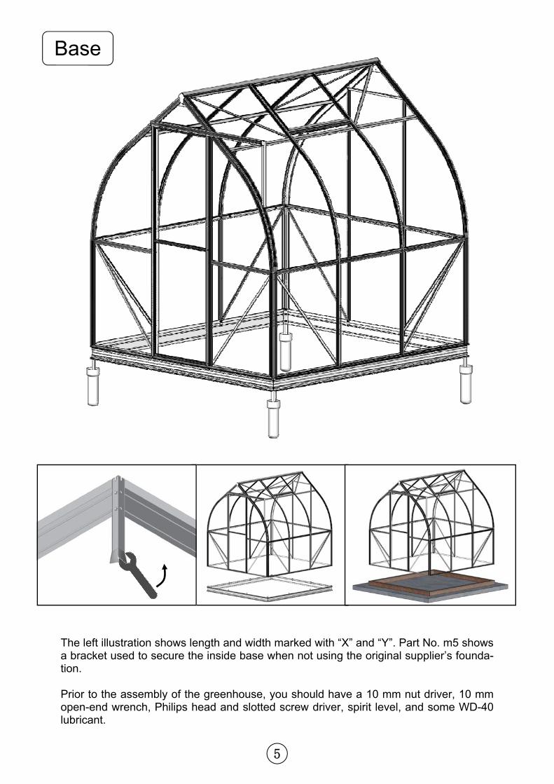
Base
The left illustration shows length and width marked with “X” and “Y”. Part No. m5 shows a bracket used to secure the inside base when not using the original supplier’s founda-tion. Prior to the assembly of the greenhouse, you should have a 10 mm nut driver, 10 mm open-end wrench, Philips head and slotted screw driver, spirit level, and some WD-40 lubricant.
6
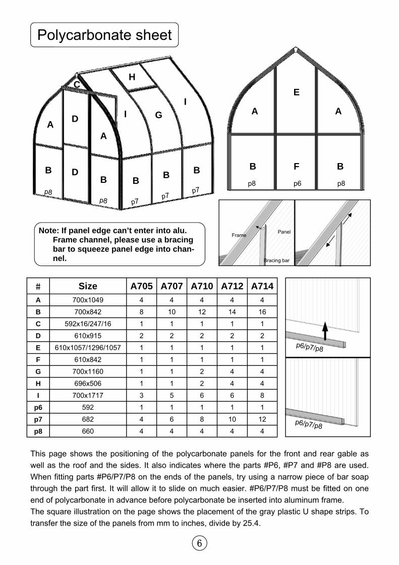
Polycarbonate sheet
# Size A705 A707 A710 A712 A714
A 700x1049 4 4 4 4 4
B 700x842 8 10 12 14 16
C 592x16/247/16 1 1 1 1 1
D 610x915 2 2 2 2 2
E 610x1057/1296/1057 1 1 1 1 1
F 610x842 1 1 1 1 1
G 700x1160 1 1 2 4 4
H 696x506 1 1 2 4 4
I 700x1717 3 5 6 6 8
p6 592 1 1 1 1 1
p7 682 4 6 8 10 12
p8 660 4 4 4 4 4
I I G A A
A A
D
D B B
B B
E
F
H C
p6 p8 p8 p8
p8 p7p7
p7
This page shows the positioning of the polycarbonate panels for the front and rear gable as
well as the roof and the sides. It also indicates where the parts #P6, #P7 and #P8 are used.
When fitting parts #P6/P7/P8 on the ends of the panels, try using a narrow piece of bar soap
through the part first. It will allow it to slide on much easier. #P6/P7/P8 must be fitted on one
end of polycarbonate in advance before polycarbonate be inserted into aluminum frame.
The square illustration on the page shows the placement of the gray plastic U shape strips. To
transfer the size of the panels from mm to inches, divide by 25.4.
p6/p7/p8
p6/p7/p8
B B
B
Frame Panel
Bracing bar
Note: If panel edge can’t enter into alu. Frame channel, please use a bracing bar to squeeze panel edge into chan-nel.
7
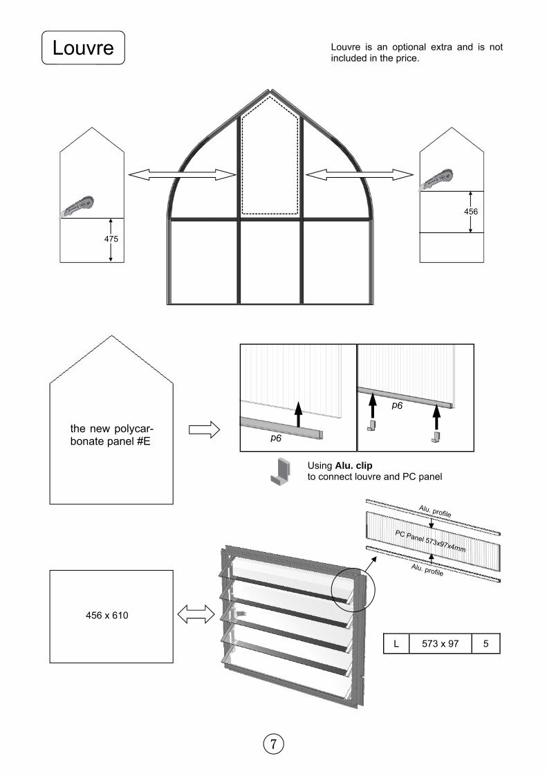
Louvre
PC Panel 573x97x4mm
Alu. profile
Alu. profile
456 x 610
L 573 x 97 5
p6
p6
the new polycar-bonate panel #E
Using Alu. clip to connect louvre and PC panel
p6
Louvre is an optional extra and is not included in the price.
475
456
8
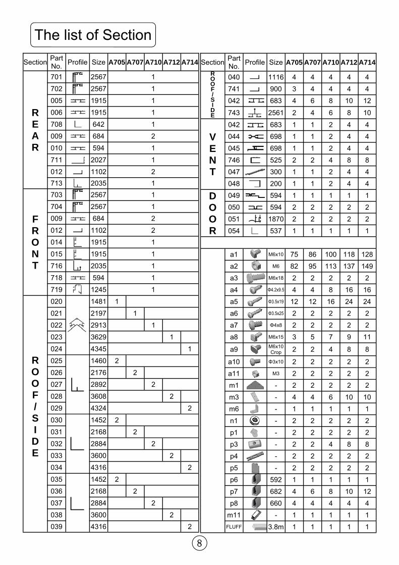
Section Part No.
Profile Size A705 A707 A710 A712 A714
R O O F / S I D E
040 1116 4 4 4 4 4
741 900 3 4 4 4 4
042 683 4 6 8 10 12
743 2561 2 4 6 8 10
V E N T
042 683 1 1 2 4 4
044 698 1 1 2 4 4
045 698 1 1 2 4 4
746 525 2 2 4 8 8
047 300 1 1 2 4 4
048 200 1 1 2 4 4
D O O R
049 594 1 1 1 1 1
050 594 2 2 2 2 2
051 1870 2 2 2 2 2
054 537 1 1 1 1 1
a1 M6x10 75 86 100 118 128
a2 M6 82 95 113 137 149
a3 M6x18 2 2 2 2 2
a4 Φ4.2x9.5 4 4 8 16 16
a5 Φ3.5x19 12 12 16 24 24
a6 Φ3.5x25 2 2 2 2 2
a7 Φ4x8 2 2 2 2 2
a8 M6x15 3 5 7 9 11
a9 M6x10 Crop 2 2 4 8 8
a10 Φ3x10 2 2 2 2 2
a11 M3 2 2 2 2 2
m1 - 2 2 2 2 2
m3 - 4 4 6 10 10
m6 - 1 1 1 1 1
n1 - 2 2 2 2 2
p1 - 2 2 2 2 2
p3 - 2 2 4 8 8
p4 - 2 2 2 2 2
p5 - 2 2 2 2 2
p6 592 1 1 1 1 1
p7 682 4 6 8 10 12
p8 660 4 4 4 4 4
m11 - 1 1 1 1 1
FLUFF 3.8m 1 1 1 1 1
The list of Section
Section Part No.
Profile Size A705 A707 A710 A712 A714
R E A R
701 2567 1
702 2567 1
005 1915 1
006 1915 1
708 642 1
009 684 2
010 594 1
711 2027 1
012 1102 2
713 2035 1
F R O N T
703 2567 1
704 2567 1
009 684 2
012 1102 2
014 1915 1
015 1915 1
716 2035 1
718 594 1
719 1245 1
R O O F / S I D E
020
1481 1
021 2197 1
022 2913 1
023 3629 1
024 4345 1
025
1460 2
026 2176 2
027 2892 2
028 3608 2
029 4324 2
030
1452 2
031 2168 2
032 2884 2
033 3600 2
034 4316 2
035
1452 2
036 2168 2
037 2884 2
038 3600 2
039 4316 2
9
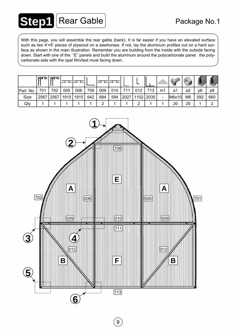
1
005 006 708 009 010 711 012 713 m1 a1 a2
1915 1915 642 684 594 2027 1102 2035 - M6x10 M6
1 1 1 2 1 1 2 1 1 20 20
701
2567
1
702
2567
1
Part No.
Size
Qty
p6
592
1
p8
660
2
708
A A
E
B B F
2
3 4
5
6
Rear Gable Step1 With this page, you will assemble the rear gable (back). It is far easier if you have an elevated surface such as two 4’×8’ pieces of plywood on a sawhorses. If not, lay the aluminum profiles out on a hard sur-face as shown in the main illustration. Remember you are building from the inside with the outside facing down. Start with one of the “E” panels and build the aluminum around the polycarbonate panel. the poly-carbonate side with the opal film/text must facing down.
Package No.1
006 005 702 701
009 010 009
711
012 012
713
10
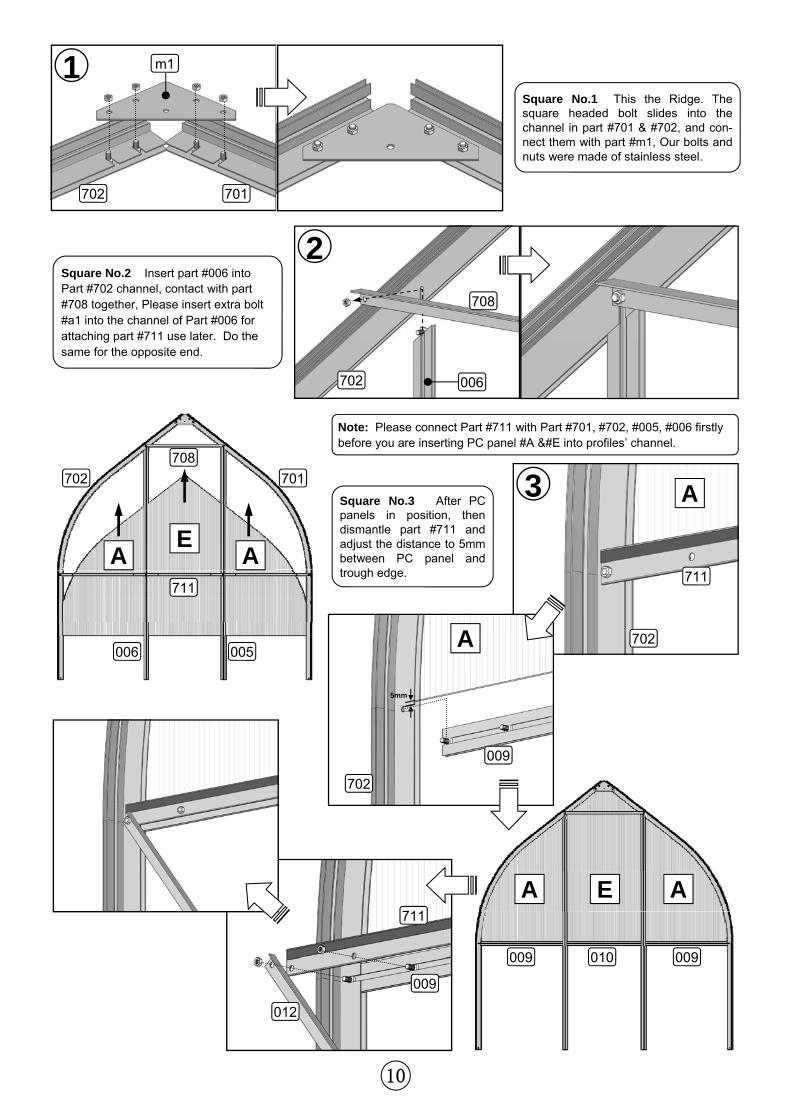
2
1 Square No.1 This the Ridge. The square headed bolt slides into the channel in part #701 & #702, and con-nect them with part #m1, Our bolts and nuts were made of stainless steel.
Square No.2 Insert part #006 into Part #702 channel, contact with part #708 together, Please insert extra bolt #a1 into the channel of Part #006 for attaching part #711 use later. Do the same for the opposite end.
Note: Please connect Part #711 with Part #701, #702, #005, #006 firstly before you are inserting PC panel #A &#E into profiles’ channel.
3 A Square No.3 After PC panels in position, then dismantle part #711 and adjust the distance to 5mm between PC panel and trough edge.
701 702
m1
708
006 702
702
711
009
012
711
702
A
009
5mm
702 701
708
711
005 006
A A E
009 009 010
A A E
11
4
B B F
5
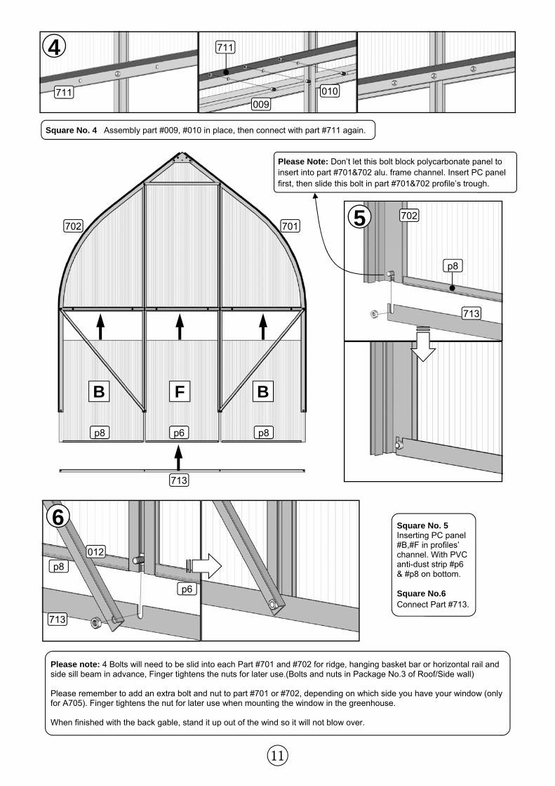
6 Square No. 5 Inserting PC panel #B,#F in profiles’ channel. With PVC anti-dust strip #p6 & #p8 on bottom. Square No.6 Connect Part #713.
Please note: 4 Bolts will need to be slid into each Part #701 and #702 for ridge, hanging basket bar or horizontal rail and side sill beam in advance, Finger tightens the nuts for later use.(Bolts and nuts in Package No.3 of Roof/Side wall) Please remember to add an extra bolt and nut to part #701 or #702, depending on which side you have your window (only for A705). Finger tightens the nut for later use when mounting the window in the greenhouse. When finished with the back gable, stand it up out of the wind so it will not blow over.
Square No. 4 Assembly part #009, #010 in place, then connect with part #711 again.
711 010
711
009
p8
713
p8 p6 p8
713
p6
713
p8
012
Please Note: Don’t let this bolt block polycarbonate panel to insert into part #701&702 alu. frame channel. Insert PC panel first, then slide this bolt in part #701&702 profile’s trough.
702 701 702
12
1
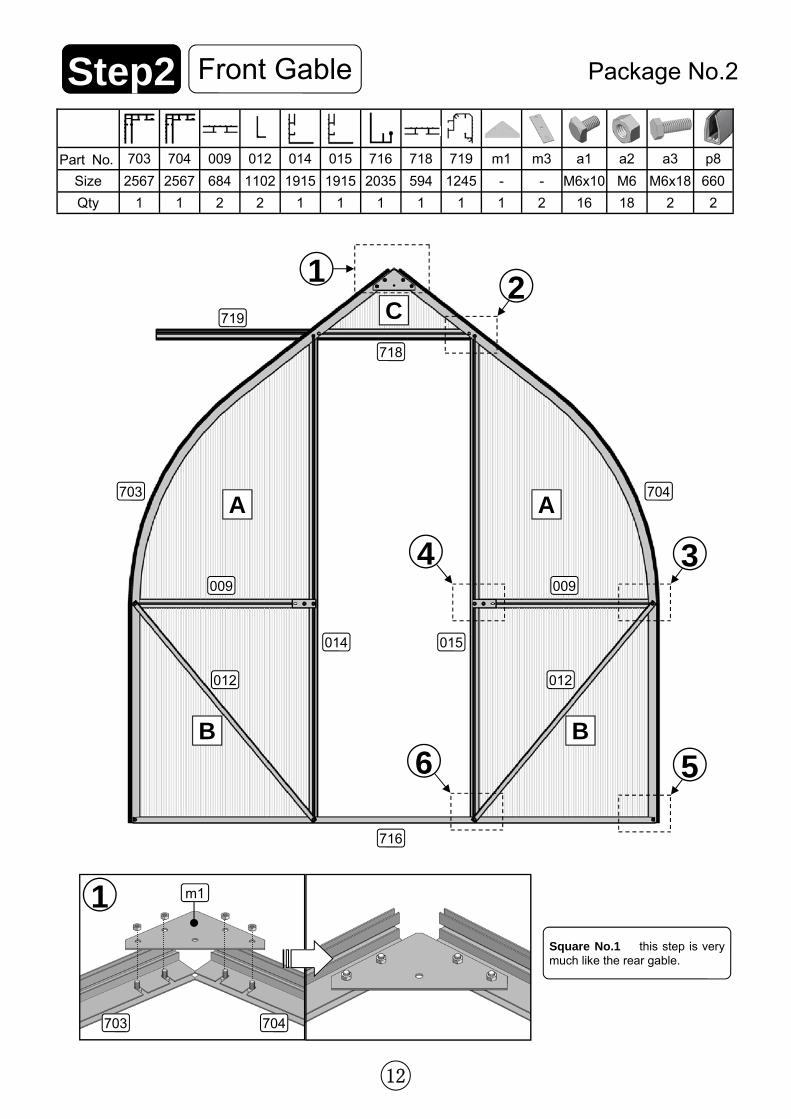
Front Gable Step2 Package No.2
Square No.1 this step is very much like the rear gable.
703 704
m1
009 012 014 015 716 718 719 m1 m3 a1 a2
684 1102 1915 1915 2035 594 1245 - - M6x10 M6
2 2 1 1 1 1 1 1 2 16 18
703
2567
1
704
2567
1
Part No.
Size
Qty
a3
M6x18
2
p8
660
2
A A
B B
009 009
703 704
012 012
716
014 015
718
719 C
1
3
5
2
6
4
13
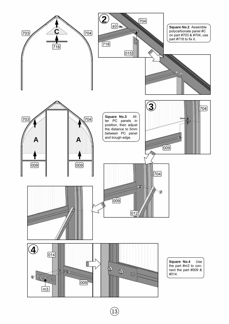
Square No.2 Assemble polycarbonate panel #C on part #703 & #704, use part #718 to fix it.
C
718
2
718
704
015
A A
009 009
3
4 014
009
m3
5mm
704
009
704
009
012
Square No.3 Af-ter PC panels in position, then adjust the distance to 5mm between PC panel and trough edge.
Square No.4 Use the part #m3 to con-nect the part #009 & #014.
a3
703 704
703 704
14
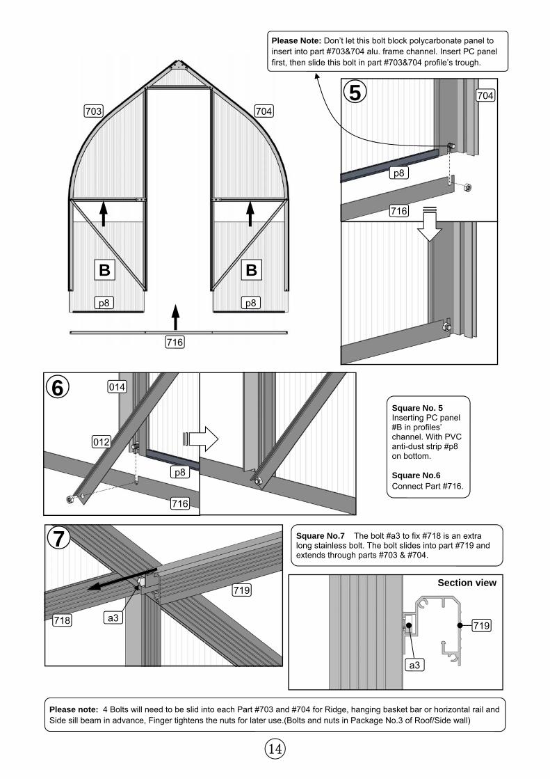
Please note: 4 Bolts will need to be slid into each Part #703 and #704 for Ridge, hanging basket bar or horizontal rail and Side sill beam in advance, Finger tightens the nuts for later use.(Bolts and nuts in Package No.3 of Roof/Side wall)
Square No.7 The bolt #a3 to fix #718 is an extra long stainless bolt. The bolt slides into part #719 and extends through parts #703 & #704.
719
a3 719
a3
B
p8
B
p8
716
5 704
716
p8
6
7
p8
716
012
014
Section view
718
Square No. 5 Inserting PC panel #B in profiles’ channel. With PVC anti-dust strip #p8 on bottom. Square No.6 Connect Part #716.
Please Note: Don’t let this bolt block polycarbonate panel to insert into part #703&704 alu. frame channel. Insert PC panel first, then slide this bolt in part #703&704 profile’s trough.
703 704
15
Part No. Size A705 A707 A710 A712 A714
020 1481 1
021 2197 1
022 2913 1
023 3629 1
024 4345 1
025 1460 2
026 2176 2
027 2892 2
028 3608 2
029 4324 2
1
2
2
1
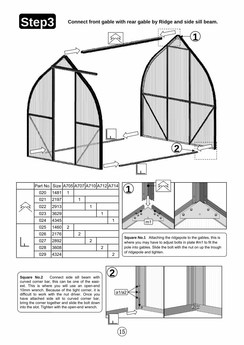
Step3 Connect front gable with rear gable by Ridge and side sill beam.
Square No.1 Attaching the ridgepole to the gables, this is where you may have to adjust bolts in plate #m1 to fit the pole into gables. Slide the bolt with the nut on up the trough of ridgepole and tighten.
Square No.2 Connect side sill beam with curved corner bar, this can be one of the easi-est. This is where you will use an open-end 10mm wrench. Because of the tight corner, it is difficult to work with the nut driver. Once you have attached side sill to curved corner bar, bring the corner together and slide the bolt down into the slot. Tighten with the open-end wrench.
m1
a1/a2
16
2
1
2
1
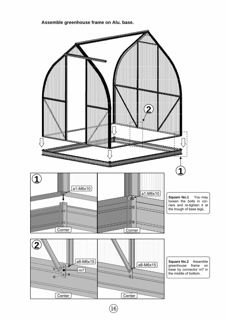
Assemble greenhouse frame on Alu. base.
m7
Square No.1 You may loosen the bolts in cor-ners and re-tighten it at the trough of base legs.
Square No.2 Assemble greenhouse frame on base by connector m7 in the middle of bottom.
Corner
Center
a1-M6x10 a1-M6x10
a8-M6x15 a8-M6x15
Corner
Center
17
2
1
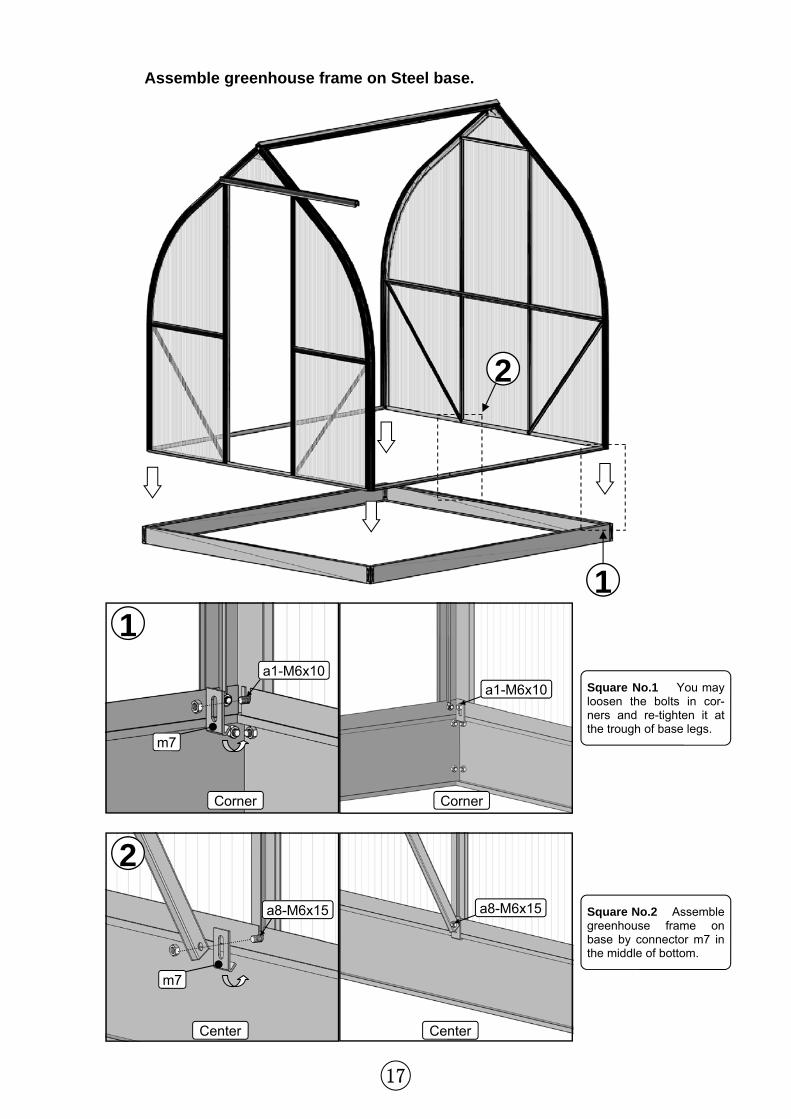
Assemble greenhouse frame on Steel base.
2
1
m7
m7
Square No.1 You may loosen the bolts in cor-ners and re-tighten it at the trough of base legs.
Square No.2 Assemble greenhouse frame on base by connector m7 in the middle of bottom.
Corner
Center
a1-M6x10 a1-M6x10
a8-M6x15 a8-M6x15
Corner
Center
18
Part No.
Size A705 A707 A710 A712 A714
030 1452 2
031 2168 2
032 2884 2
033 3600 2
034 4316 2
035 1452 2
036 2168 2
037 2884 2
038 3600 2
039 4316 2
040 1116 4 4 4 4 4
741 900 3 4 4 4 4
042 683 4 6 8 10 12
743 2561 2 4 6 8 10
a1 M6x10 33 44 54 64 74
a2 M6 35 48 60 72 84
a8 M6x15 2 4 6 8 10
p7 682 4 6 8 10 12
1
2
3
3 4
2
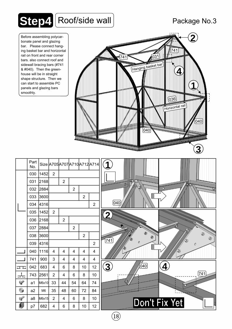
Roof/side wall Step4 Package No.3
Before assembling polycar-bonate panel and glazing bar. Please connect hang-ing basket bar and horizontal rail on front and rear corner bars. also connect roof and sidewall bracing bars (#741 & #040). Then the green-house will be in straight shape structure. Then we can start to assemble PC panels and glazing bars smoothly.
040
040
741
741
741
040
741
1
040
Hanging basket bar
Horizontal rail
4
031
036
19
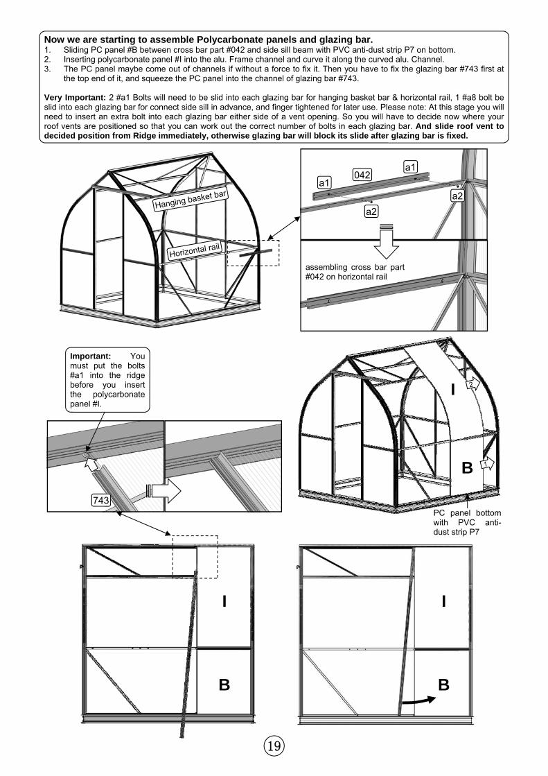
Now we are starting to assemble Polycarbonate panels and glazing bar. 1. Sliding PC panel #B between cross bar part #042 and side sill beam with PVC anti-dust strip P7 on bottom. 2. Inserting polycarbonate panel #I into the alu. Frame channel and curve it along the curved alu. Channel. 3. The PC panel maybe come out of channels if without a force to fix it. Then you have to fix the glazing bar #743 first at
the top end of it, and squeeze the PC panel into the channel of glazing bar #743. Very Important: 2 #a1 Bolts will need to be slid into each glazing bar for hanging basket bar & horizontal rail, 1 #a8 bolt be slid into each glazing bar for connect side sill in advance, and finger tightened for later use. Please note: At this stage you will need to insert an extra bolt into each glazing bar either side of a vent opening. So you will have to decide now where your roof vents are positioned so that you can work out the correct number of bolts in each glazing bar. And slide roof vent to decided position from Ridge immediately, otherwise glazing bar will block its slide after glazing bar is fixed.
743
Important: You must put the bolts #a1 into the ridge before you insert the polycarbonate panel #I.
PC panel bottom with PVC anti-dust strip P7
B
I
042
Hanging basket bar
Horizontal rail
a1
a2
a1
a2
assembling cross bar part #042 on horizontal rail
1
2
I
B
I
B
20
1 2
3
3
2
1
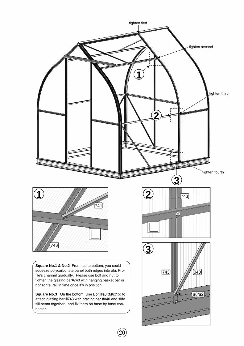
Square No.1 & No.2 From top to bottom, you could squeeze polycarbonate panel both edges into alu. Pro-file’s channel gradually. Please use bolt and nut to tighten the glazing bar#743 with hanging basket bar or horizontal rail in time once it’s in position.
Square No.3 On the bottom, Use Bolt #a8 (M6x15) to attach glazing bar #743 with bracing bar #040 and side sill beam together, and fix them on base by base con-nector.
743
741
743
743 040
a8/a2
tighten first
tighten second
tighten third
tighten fourth
21
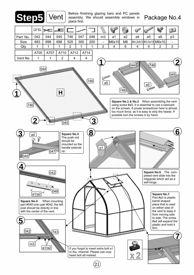
Part No. 042 044 045 746 047 048 m3 a1 a2 a4 a5 p3
Size 683 698 698 525 300 200 - M6x10 M6 Φ4.2x9.5 Φ3.5x19 - Qty 1 1 1 2 1 1 2 4 6 4 4 2
a9
M6x10 2
A705 A707 A710 A712 A714
Vent No. 1 1 2 4 4
H 1
2 3
1 2
3 8
4
5
6
7
Vent Step5 Package No.4
Square No.1 & No.2 When assembling the vent using screw #a5, it is essential to use a lubricant on the screws. A power screwdriver here is almost too much force, as it is easy to strip the heads. If possible turn the screws in by hand.
Square No.3 The push rod should be mounted so the handle extends up.
Square No.4 When mounting part #048 onto part #042, the left post should be directly in line with the center of the vent.
Square No.6 The com-pleted vent slide into the ridgepole which act as a self-hinge.
Square No.7 Part #p3 is plastic barrel shaped piece that is used on either side of the vent to keep it from moving side to side. The screw #a4 will expand the plastic and hold it firm.
044
a5
746
746
a5
045
044
746
746
045
p1
045 047
a4
042
048 a1/a2
743 042
m3 a1/a2
Before finishing glazing bars and PC panels assembly. We should assemble windows in place first.
If you forgot to insert extra bolt a1 in Alu. channel. Please use crop head bolt a9 instead.
22
Step6
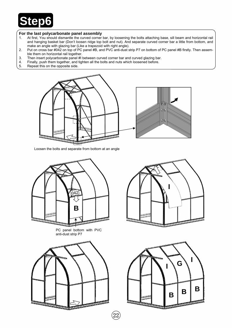
Loosen the bolts and separate from bottom at an angle
B
PC panel bottom with PVC anti-dust strip P7
042 I
B B B
I G I
For the last polycarbonate panel assembly 1. At first, You should dismantle the curved corner bar, by loosening the bolts attaching base, sill beam and horizontal rail
and hanging basket bar (Don’t loosen ridge top bolt and nut). And separate curved corner bar a little from bottom, and make an angle with glazing bar (Like a trapezoid with right angle).
2. Put on cross bar #042 on top of PC panel #B, and PVC anti-dust strip P7 on bottom of PC panel #B firstly. Then assem-ble them on horizontal rail together.
3. Then insert polycarbonate panel #I between curved corner bar and curved glazing bar. 4. Finally, push them together, and tighten all the bolts and nuts which loosened before. 5. Repeat this on the opposite side.
23
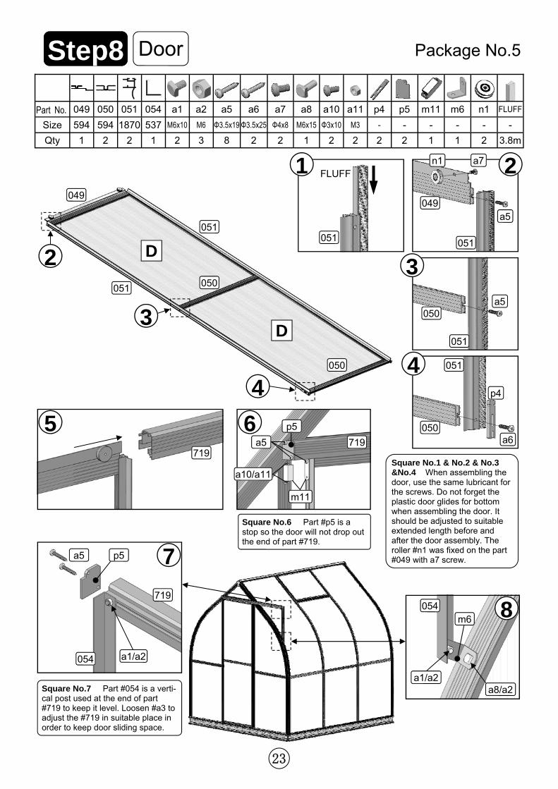
Part No. 049 050 051 054 a1 a2 a5 a6 a7 a8 p4 p5
Size 594 594 1870 537 M6x10 M6 Φ3.5x19 Φ3.5x25 Φ4x8 M6x15 - -
Qty 1 2 2 1 2 3 8 2 2 1 2 2
n1
-
2
m6
-
1
a10
Φ3x10
2
a11
M3
2
m11
-
1
FLUFF
-
3.8m
D 2
D 3
4
5 6
7
8
Door Step8 Package No.5
Square No.1 & No.2 & No.3 &No.4 When assembling the door, use the same lubricant for the screws. Do not forget the plastic door glides for bottom when assembling the door. It should be adjusted to suitable extended length before and after the door assembly. The roller #n1 was fixed on the part #049 with a7 screw.
Square No.6 Part #p5 is a stop so the door will not drop out the end of part #719.
Square No.7 Part #054 is a verti-cal post used at the end of part #719 to keep it level. Loosen #a3 to adjust the #719 in suitable place in order to keep door sliding space.
051
049
050
050
051
719 719 a5
p5
p5 a5
719
054 a1/a2
054 m6
a1/a2 a8/a2
a10/a11
m11
3
4 051
a5 050
050
051
p4
a6
1 2
051 051
049
n1 a7
a5
FLUFF
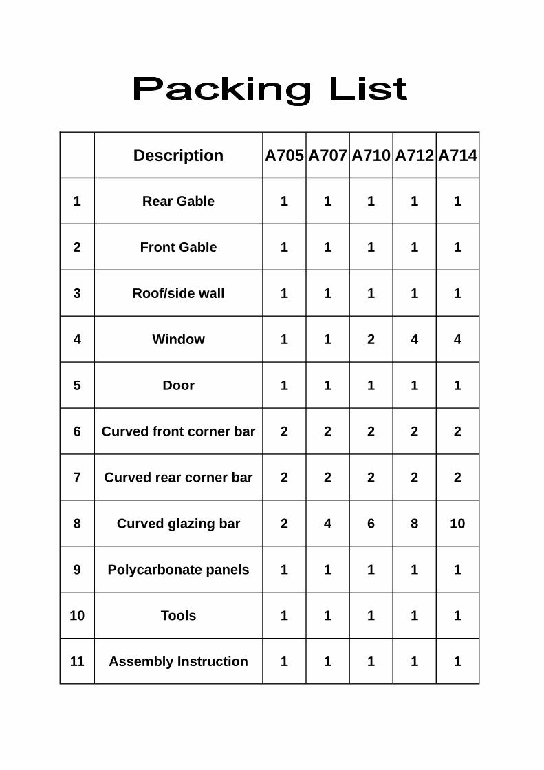
Description A705 A707 A710 A712 A714
1 Rear Gable 1 1 1 1 1
2 Front Gable 1 1 1 1 1
3 Roof/side wall 1 1 1 1 1
4 Window 1 1 2 4 4
5 Door 1 1 1 1 1
6 Curved front corner bar 2 2 2 2 2
7 Curved rear corner bar 2 2 2 2 2
8 Curved glazing bar 2 4 6 8 10
9 Polycarbonate panels 1 1 1 1 1
10 Tools 1 1 1 1 1
11 Assembly Instruction 1 1 1 1 1