A semi-generative approach to computer-aided process planning using group technology
11
Computers ind. Engng Vol. 14, No. 2, pp. 12%i37, 1988 0360-8352/88 $3.00+0.00 Printed in Great Britain Pergamon Press plc A SEMI-GENERATIVE APPROACH TO COMPUTER-AIDED PROCESS PLANNING USING GROUP TECHNOLOGY LI LIN and DAVID D . BEDWORTH Department of Industrial and Management Systems Engineering, Arizona State University, Tempe, AZ 85287-5906, U.S.A. (Received for publication 8 July 1987) Abstract--Computer-Aided Process Planning (CAPP) has a key role in Computer-Integrated Manufacturing (CIM) as an interface between design and manufacturing. This paper reports on a research effort that had as a major thrust the demonstration that a correctly designed Group Technology (GT) part coding scheme can assist in generating the sequence of machine operations for making the part. To exemplify the approach, a 14-digit chain-structured GT code was designed to capture the part features for the most common rotational/gear part shapes using DCLASS information processing trees. The GT code was then processed to generate process plans using a semi-generative CAPP approach that integrates sets of machining operations for part basic shapes and form features. The results have shown promising perspectives of GT applications in CAPP. INTRODUCTION In a manufacturing production system, process planning has always been the most important interface between product design and manufacturing [1,2]. A process plan typically consists of (1) a list of processes to be performed in a specified sequence, (2) machine and tool selections and (3) process parameters such as machining dimensions and tolerances required to allow the part to be fabricated on the shop floor [3,4]. Traditional process planning is an extremely complex and time consuming task requir- ing a tremendous amount of expertise. This product oriented activity is performed by process planners who are normally knowledgeable manufacturing engineers with experi- ence in machining, tooling and other shop floor production requirements. The quality of the process plan totally depends on the planners' sophistication [1,4]. Although old process plans may be used as references for similar parts, a large amount of duplication is done due to the lack of information retrieval and comparison techniques. Also, even for the same part, it is very rare for two process planners to generate one identical process plan, unless the processes are extremely simple [5]. Therefore, manufacturing produc- tion consistency and optimization is impossible to achieve. As a consequence, planning and manufacturing costs are increased because of the duplication effort in process planning as well as excessive tooling and material inventory. Production lead times also increase due to ineffective planning. All these increased costs can be detrimental to a manufacturing company in today's highly competitive market. With advanced computer technology, this difficult task can be achieved by Computer Aided Process Planning (CAPP). The CAPP system processes the part design inform- ation pertinent to manufacturing operations based on similar process plans or on decision logic built into the system by process planners and programmers. CAPP then generates the required process plan. A significantly valuable tool for the development of CAPP is Group Technology (GT), which can be characterized as "the operating management philosophy based on the recognition that similarities occur in the conception, design, sale, manufacture and support of discrete products" [2]. By using GT, parts with similar attributes can be classified and coded into part families to simplify and speed up process planning and manufacturing. The benefits of utilizing GT in the entire manufacturing process has been reported to have 10% to 80% savings in parts design and drawing, production and quality control costs, setup and throughput time, raw materials, work-in-process and finished goods inventory [2,6]. 127
Transcript of A semi-generative approach to computer-aided process planning using group technology

Computers ind. Engng Vol. 14, No. 2, pp. 12%i37, 1988 0360-8352/88 $3.00+0.00 Printed in Great Britain Pergamon Press plc
A S E M I - G E N E R A T I V E A P P R O A C H T O C O M P U T E R - A I D E D P R O C E S S P L A N N I N G U S I N G G R O U P T E C H N O L O G Y
LI LIN and DAVID D. BEDWORTH Department of Industrial and Management Systems Engineering, Arizona State University, Tempe,
AZ 85287-5906, U.S.A.
(Received for publication 8 July 1987)
Abstract--Computer-Aided Process Planning (CAPP) has a key role in Computer-Integrated Manufacturing (CIM) as an interface between design and manufacturing. This paper reports on a research effort that had as a major thrust the demonstration that a correctly designed Group Technology (GT) part coding scheme can assist in generating the sequence of machine operations for making the part. To exemplify the approach, a 14-digit chain-structured GT code was designed to capture the part features for the most common rotational/gear part shapes using DCLASS information processing trees. The GT code was then processed to generate process plans using a semi-generative CAPP approach that integrates sets of machining operations for part basic shapes and form features. The results have shown promising perspectives of GT applications in CAPP.
INTRODUCTION
In a manufacturing production system, process planning has always been the most important interface between product design and manufacturing [1,2]. A process plan typically consists of (1) a list of processes to be performed in a specified sequence, (2) machine and tool selections and (3) process parameters such as machining dimensions and tolerances required to allow the part to be fabricated on the shop floor [3,4].
Traditional process planning is an extremely complex and time consuming task requir- ing a tremendous amount of expertise. This product oriented activity is performed by process planners who are normally knowledgeable manufacturing engineers with experi- ence in machining, tooling and other shop floor production requirements. The quality of the process plan totally depends on the planners' sophistication [1,4]. Although old process plans may be used as references for similar parts, a large amount of duplication is done due to the lack of information retrieval and comparison techniques. Also, even for the same part, it is very rare for two process planners to generate one identical process plan, unless the processes are extremely simple [5]. Therefore, manufacturing produc- tion consistency and optimization is impossible to achieve. As a consequence, planning and manufacturing costs are increased because of the duplication effort in process planning as well as excessive tooling and material inventory. Production lead times also increase due to ineffective planning. All these increased costs can be detrimental to a manufacturing company in today's highly competitive market.
With advanced computer technology, this difficult task can be achieved by Computer Aided Process Planning (CAPP). The CAPP system processes the part design inform- ation pertinent to manufacturing operations based on similar process plans or on decision logic built into the system by process planners and programmers. CAPP then generates the required process plan.
A significantly valuable tool for the development of CAPP is Group Technology (GT), which can be characterized as "the operating management philosophy based on the recognition that similarities occur in the conception, design, sale, manufacture and support of discrete products" [2]. By using GT, parts with similar attributes can be classified and coded into part families to simplify and speed up process planning and manufacturing. The benefits of utilizing GT in the entire manufacturing process has been reported to have 10% to 80% savings in parts design and drawing, production and quality control costs, setup and throughput time, raw materials, work-in-process and finished goods inventory [2,6].
127
128 LI LIN and DAVID D. BEDWORTH
The purpose of this paper is to demonstrate how a properly designed GT code capturing features of a designed part can be used in generating the sequence of oper- ations for making the part. Part coding and process planning using GT is demonstrated using an example based on a research project that designed and developed a CAPP system for rotational and gear parts (ASUPLAN) [7]. An information processing system developed at Brigham Young University, DCLASS [8,9], was used as the tool for part coding information collection and processing planning to generate a process plan for the part.
GT PART FAMILY AND CODE STRUCTURES
The part family concept is a traditional Group Technology application in which related parts with similar attributes such as geometric shape or manufacturing process require- ments are grouped [10].
From a manufacturing point of view, parts' similarities are identified according to the common manufacturing processes required to make the parts [6]. An example is that similar external and internal shapes of rotational parts can be fabricated by the same type of machine operation, say turning. This machine operation oriented classification and coding method can provide an excellent interface between design and manufacturing.
In designing a GT part coding system, there are three basic GT code structures [6,11]. Monocode is a code with a hierarchical tree structure in which the meaning of a code digit is dependent on its preceding digit. Such a code can contain a large amount of information, but since a series of code digits must be interpreted together, it is not easy to understand and to be processed by a computer. Polycode, also called feature code, has a chain-type structure that allows code symbols to be interpreted independently of one another. This coding scheme is easy to develop and understand but typically gets relatively long due to the limited code capacity. A mixture of monocode and polycode, hybridcode, also called mixed-mode code, combines the advantage of easy interpretation found in a polycode while still containing large amounts of information within a relatively short code using the monocode part as connectors for the polycode segments.
COMPUTER AIDED PROCESS PLANNING
Since a GT part classification and coding system can transform part basic shape, form features, dimensions and tolerances, material, and so on into a code, this information can be available to a CAPP system for the consistent generation of required process plans. Some large productivity increases have been reported as the result of utilizing GT and CAPP [12] though the use of a properly designed GT code to facilitate generation of process plans is not widely disseminated.
There are two approaches used in developing and implementing CAPP systems: variant and generative. The variant CAPP system develops process plans based on existing process plans for similar parts that have been classified and coded t~tilizing GT. Standard plans for identified part families are first constructed and stored in the com- puter data base with the GT code as retrieving keys [13]. A part is classified and coded into one of the part families and the corresponding standard plan is retrieved from the data base. Since there can only be a limited number of standard plans, human modifica- tions to the standard plan are normally necessary, especially for new parts that have variations with the existing part families.
Generative process planning is a system that can synthesize process information contained in GT code in order to create a process plan for a new part automatically. Part design data is input to the system and the unique process plan is generated by the computer based on process planning decision rules and algorithms. The advantages of the generative process planning approach have been listed by Chang [13] as:
(1) consistent process plans can be generated efficiently; (2) new parts can be planned as easily as existing parts;

Group technology 129
(3) potential interface with an automated manufacturing system can provide detailed real-time control information.
To develop a generative process planning system, part design data pertinent to the manufacturing processes can be transformed into the computer data base using GT classification and coding systems. However, a major effort is required for the creation and incorporation of decision rules into a computer model.
THE ASUPLAN PROCESS PLANNING DEVELOPMENT METHOD
As discussed earlier, variant process planning generates standard process plans for limited part families and uses GT code to extract a process plan of its family and allow necessary modifications. This is a useful approach to the mass-production company that manufactures limited kinds of parts over and over again. If the variation of part features is small, a variant process planning system can be very accurate.
A generative process planning system, on the other hand, does not rely on standard process plans of existing part families for each part to be process planned but generates the process plans according to each part's geometric features. This approach obviously has the advantages of flexibility and versatility. However, the process planning logic and algorithm are much more difficult to develop.
From the Group Technology viewpoint, there is basically no qualitative difference between the two approaches. It is just a matter of how detailed the design of the front- end coding scheme for a CAPP system should be and how the code should be processed to get the process plan. The variant method processes the code and stores the machining operations in groups by part families while the generative method processes the code in much smaller increments and treats machining processes as separate operations for individual part features. To illustrate this point, a parallel example is the difference in building an apartment complex with factory-made room modules or with raw bricks and wood. With room modules, which resembles the variant approach, one can build a limited variety of houses with less effort and time, whereas in the generative approach, anything can be built with raw bricks and wood. The latter is far more flexible than the former but requires more skill and time.
A CAPP method combining the two approaches can be considered semi-generative. Marion [14] discussed a GT-based semi-generative approach to CAPP for assembly of electronic parts. Two stages are involved in the process planning: operation selection and operation sequencing. The GT code is used by an inference mechanism to select the part- specific operations. A carefully constructed master process plan is then used to sequence these operations by pruning undesired operations from the master plan to produce a part-specific plan.
The research described in this paper used a semi-generative type approach for the CAPP system for two primary reasons: (1) to combine the advantage of flexibility in generative process planning with the simplicity of variant process planning, and (2) to fully use the information processing and decision logic power of the DCLASS system information processing trees. A major effort in the semi-generative process planning approach was to combine the operation selection and operation sequencing into one single step. This required careful planning starting at the coding scheme design stage.
THE ASUPLAN SYSTEM STRUCTURE
The general system structure for the rotational/gear part classification and coding scheme and process planning system, ASUPLAN, is depicted in Fig. 1. A computer mainline program written in FORTRAN calls DCLASS as a subprogram and the part coding DCLASS trees are traversed. The user selects from menu items posed on the computer screen and the ASUPLAN system will display the part GT code on the screen.
When the interactive part coding process is completed, the DCLASS process planning trees are then traversed automatically by the ASUPLAN system. All part geometry and

130 LI LIN and DAVID D. BEDWORTH
I co
/ (
Part Codlnq
i Machine Operations I
Selection & Sequencing
Equipment, Tool Machine Operations
Information
Equipment, Tool Coding
1 Equipment, Tool
Matching
i t l I : anu,actu,,ng Post-processing Database
_ I
// I [
I
Fig. 1. ASUPLAN system general structure.
form features coded are processed by the process planning function and the needed machine operations are selected in appropriate sequence. A tabulated process plan, including operation numbers, machine operations, equipment and tools, is produced by a post-processor.
In order to obtain a process plan that includes sufficient machining information for the manufacturing shop floor, part classification and coding using GT code is the first as well as the most important step. Since existing part coding systems were designed for general classification purposes and could not provide sufficient information to allow the complex tasks of CAPP for this research, a GT code for rotational and gear parts had to be designed.
THE ASUPLAN SYSTEM PART CODING SCHEME
In designing a part classification and coding scheme, the most important step is to determine what characteristics the code should be able to capture. A Group Technology code can be developed in many ways to satisfy various purposes. Since this research was to develop a GT coding scheme to allow the generation of a generalized machining process plan for making rotational/gear parts, part geometric characteristics, i.e. shape and form features that directly determine the machining processes, should be contained in the GT code.
The next step was to determine the coding structure for the part classification and coding scheme. If a part is coded by a tree-type monocode, meaning one kind of part basic shape is represented by more than one code digit, the code will have to be processed in the way the digits are grouped. Figure 2 shows a portion of the part code designed at Brigham Young University using DCLASS, where three digits are used for part basic shapes. AXX is used for any part without a through-bore hole and BXX represents any part with a through-bore hole. Two parts with the same external shape have as their only difference one through-bore hole, but their codes can be very different. For instance, A10 and B l l have two digits different but the only part difference is a through-bore hole. It can be seen that much difficulty will be encountered in designing the process planning logic using such a code. There must be two different interpretation logic schemes in order to manufacture the two parts in the same machine sequence for their external shapes.

Group technology 131
BASIC SHAPES
A00
AIO
A20
@ A30
B01
B l l
B21
O B31
~ 2
B12
B22
B03
IN B13
I
B23
B04
D B14
Fig. 2. DCLASS part basic shape definition. (From D. K. Allen and P. R. Smith, Part family classification and coding, Monograph No. 3, Computer Aided Manufacturing Laboratory, Brigham Young University, Provo,
Utah, 1982.)
Monocode is more appropriate for variant process planning where GT code is used only to extract the pre-determined standard plans. For a chain-type polycode, if each digit is used to represent one part feature, it is feasible to form a set of machining operations corresponding to each of the part features. For this reason, a chain-type polycode was selected for the problem at hand.
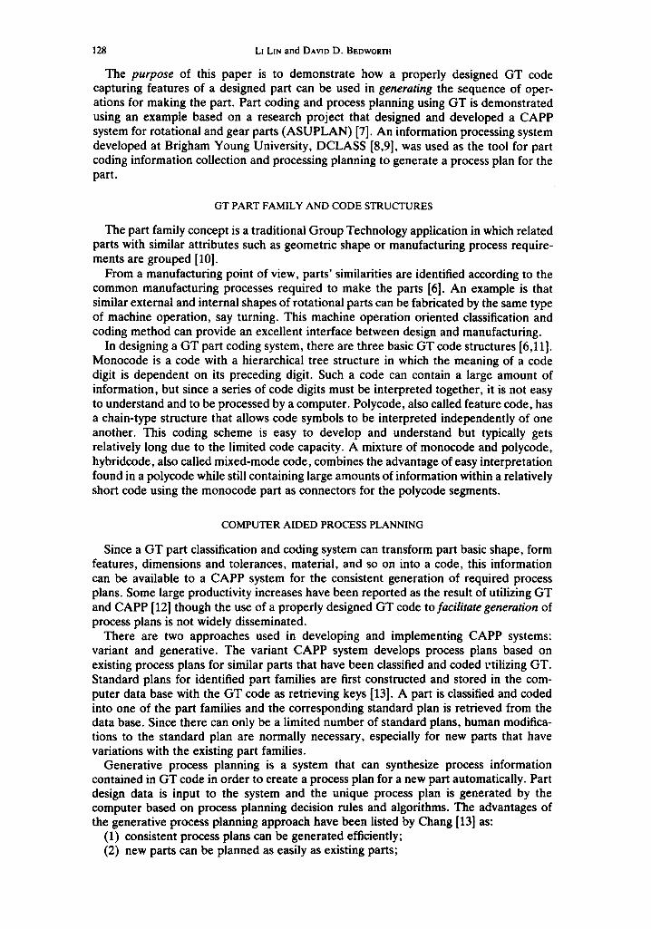
Since the purpose for classifying and coding a designed part was to generate a process plan automatically, the coding scheme was designed to satisfy the process planning function. Figure 3 graphically presents the coding scheme. Code digits are grouped into sections according to part feature groups. The first section, part basic shape, is the major part of the code. Figure 4 shows a portion of the basic shape definition of the ASUPLAN system.
In designing a GT coding scheme, there is a tradeoff between simplicity and sophistica- tion. To what degree of detail should the coding scheme be designed really depends on the expected capability of the system. The system should capture sufficient information in order to carry out the complex process planning function. On the other hand, if too much information is put in the code the essence of forming GT part families for simplicity of operation is lost. Based on these considerations, an effort was made to design the coding scheme for ASUPLAN to cover sufficient information for CAPP while keeping it simple.
Although part basic shapes and major form features are captured by the GT code, other minor features should not be neglected, such as position and orientation of chamfers, grooves, threads and slots on the part. If they are not taken into account in process planning it is impossible to place the needed machine operations in the appro- priate sequence. A thorough solution to this problem is to code all form features and their positions but this will cause the GT code to grow into an enormous length and the sense of a GT part family is completely lost.
To resolve the problem, a compromise approach was used. Form feature positions are defined by the user during part coding and are stored in some internal variables within the DCLASS trees for process planning use. Although not coded, these internal vari- ables are treated effectively by the process planning function to generate a complete process plan including machine operations for part basic shapes and form features at their designated positions.

132 Lm LIN and DAVID D. BEDWORTH
I4-DIGIT ASUPLAN PART GT CODE
BASIC SHAPE FORH FEATURES GEAR FEATURES SIZE RANGE PRECISION ;IATERIAL
I°I°I-I.I, I, I oi-I, I, 14 I-I,I Ex[ernal I
Internal I Cyllndrical Surface I
Chamfer/ Thread
Hole Slot/Face
T- -
Oe,! Type
Tooth Form
D.P. Range
Tooth # Range
I Dmax
Lmax
I Precision
Level l.laterlaI
Type
I
Fig. 3. 14-digit ASUPLAN part GT code.
The information contained in the ASUPLAN 14-digit code only includes the major features of part families as well as the position of form features that will affect machining sequence, especially turning operations, which are coded in the form of output keys to be used later as input keys in process planning but are not shown in the code itself. Variation in dimension for parts with similar shapes does not change the part family to which the parts belong and therefore their machining operations sequence for major features are still the same. The capture of form feature position in the ASUPLAN system has gone further than many of the existing coding systems. In the coding scheme, positions of chamfers, grooves, face rings, threads, auxiliary holes, face shapings and slots are captured. Another purpose of this design is the potential to allow inclusion of the numerical control (NC) tape generation function. If all shape and feature positions and associated dimensions can be defined, NC tapes should be feasible to produce.
THE ASUPLAN PROCESS PLANNING HIERARCHICAL LOGIC
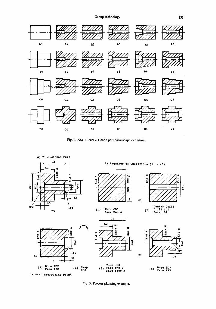
Since the chain-type polycode structure is used, an effective way to design machine operation selection and sequencing is to develop totally independent machine operations for each basic shape and then combine them together with minor feature machining operations to form a complete process plan. An example of this hierarchical logic for the part basic shape machining is shown in Fig. 5. The machining sequence for the external shape of a two-outer-diameter part is designed first and a number of interposing points are identified so that only at these points would the machining operation for the internal shapes be allowed. The key point in machine operations selection and sequencing is to identify the reference dimension which is the part face which major dimensions are referred to. For instance, the part shown in Fig. 5 has the reference dimension on End A along the axial direction as the common referencing point for major part length dimen- sions L1, L2 and L3. In the diameter direction of a rotational part, all cylindrical dimensions are normally referred to the center axis. These reference faces are carefully selected in the design stage so that the manufacturing of desirable dimensions and tolerances can be feasible on the machines. Process planning of a part should pay full
AO
Group technology
A1 A2 A3
BO B1 B2 B3
CO C1 C2 C3
DO DI D2 D3
133
A4 A5
B4 B5
C4 C5
D4 D5
Fig. 4. ASUPLAN GT code part basic shape definition.
A) D i m e n s i o n e d Part
L1
xJ- L3
B5
m
N
I ~ L4
I F 3
B o r e ID2 ( 3 ) F a c e I F 2
2
( 4 ) Swap End
I x - - - I n t e r p o s i n g p o i n t
B) Sequence o f O p e r a t i o n s ( 1 ) - ( 5 )
XO
m
ILl
( i ) T u r n ODI ( 2 ) F a c e End A
L1
• m
I N
8
Center Drill Drill IDI Bore IDI
I2
m
r / / / I ~.4' -
T u r n OD2 ( 5 ) F a c e End B
Face Face H B o r e XD3
( 6 ) F a c e I F 3
Fig. 5. Process planning example.

134 Ll LIN and DAVID D. BEDWOR'rH
respect to its reference dimensions. This is directly related to the first decision in process planning of which side of the part, End A or End B, should be cut first.
In Fig. 5, if the non-reference dimension End B is to be cut first and then Face H facing the same side is cut, the length between End B and Face H is not dimensioned and will thus be difficult to cut. Even if the difference of L1 and L2 is used for cutting Face H, (which is a very bad execution), it will be impossible to meet dimension and tolerance requirements of L1 and L2 simultaneously by merely cutting End A after the part's ends are swapped. Therefore, the rule of thumb is to start by cutting reference dimension End A first and when the part's ends are swapped, L1 and L2 can be realized by cutting End B and Face H respectively. At interposing point I0 and I1, before swapping part ends, internal basic shapes as well as center hole drilling and boring can be accomplished. Furthermore, any other part form features, say a right chamfer, that can only be cut from the B side should be done as well, otherwise another end swapping and chucking will become necessary later, which would be a waste of time.
The complete procedure for generating a process plan for a rotational/gear part using the ASUPLAN system is shown in Fig. 6. After a part is coded, its external basic shape is checked by examining the first character of the code and the corresponding machine operation sequence for making one side of the external shape (end), usually the reference dimension, will be started. At each interposing point where internal basic machining is allowed, the code representing the internal basic shape will be checked and appropriate machining processes will be put into the process sequence. For the starting side, machining of all turning features represented by the third code digit (chamfers, grooves) and the fourth code digit (threads) will be performed before the part is turned around (swap) and chucked on the other side (end). For the other side, basic internal shape of the part is checked again and the turning features are also made. In the flow chart, the machining processes of only one external basic shape is shown completely and the remaining external shapes containing the same flow sequence are shown as dotted lines.
At point A in the figure, all turning machining operations are finished. If there are other features for the part as represented in the fifth code digit (auxiliary holes) and the sixth code digit (face, slot), machining operations will be accommodated accordingly. For a gear part, gear cutting processes will be selected and heat treatment will be made, since a majority of gear parts will require teeth surface hardening. Grinding operations are selected after heat treatment when the part precision requirement is high. In the last step, final inspection should be applicable to all parts.
A unique feature of the process planning system is that machine operations selection and sequencing are done in one single step. As Marion [14] discussed in a paper about an electronic assembly process planning system, processes are determined first and then sequenced. Expert systems were recommended in the operation sequencing since there are many rules for decision-making. In ASUPLAN, the decision-making rules for machining operation selection and sequencing are integrated into one structure--the coding tree output keys. With these keys used as rules, operations are selected in appropriate sequence. An example of such a generated plan is given in Fig. 7.
COMPUTER REQUIREMENTS FOR ASUPLAN
The minimum computer configuration to run ASUPLAN is listed as follows [9]:
Hardware - - IBM PC Model XT with 512K RAM - - 10 MB Winchester Hard Disk - - Monochrome or graphics display - - Printer - - DCLASS interface box
Software - - DCLASS system - - IBM standard DOS 2.0 or higher - - Microsoft FORTRAN 3.20.

Group technology 135
T i
"k ~ i _ _ _ I n : ~ l I I ~ : n . . . .
E
gl

136 L: Lir~ and D^VlD D. BEDWORTH
CONCLUSIONS
This research has demonstrated an important application of Group Technology (GT) in Computer Aided Process Planning (CAPP) through the design and development of the ASUPLAN system. ASUPLAN shows that it is feasible to use a GT code to capture the part information required to generate a process plan for the manufacturing shop floor. The semi-generative approach shows, as discussed earlier, that there is basically no qualitative difference in variant and generative process planning approaches. The only factor separating the two, if GT is used in the process planning, is how detailed the part is coded and how the corresponding machining operations are organized.
In using DCLASS in the development of a CAPP system, the potential for the decision trees has been demonstrated. An intensive effort has to be made in the design of the GT code in order to allow a semi-generative CAPP system to be effective. The addition of manufacturing time and cost estimations should be realizable through the capture of all part dimensions and incorporation of an appropriate algorithm.
PART NAME: DEHD ~ PART NUMBER: DS 123"-LL
PLANNER: LIN, L: DATE: 10/29/8b
PART ST CODE = D3-5212-1344-34-2- I
OP N n . OPERATION EQUIP TOOL . . . . . . . . . . . . . . . . . . . . . . . . . . . . . . . . . . . . . . . . . . . . . . . . . . . . . . . . . .
10 ROUGH TURN OUTER DIAMETER ( O . D . ) 2 A1 A41
20 F I N I S H TURN OUTER DIAMETER ( O . D . ) 2 A1 R42
3 0 F I N I S H TURN OUTER DIAMETER ( Q . D . ) 1 A1 A42
40 FACE FACE A A1 A32
50 FACE END A A1 A32
bO TURN LEFT OUTER CI.IAHFF.RB A: A42
7 0 TURN FACE RING ON FRCF. A A I A42
80 CENTER DRILL A: A01
90 DRILL INNER DIA~V~TER ( I . D . ) I A: A61
100 BORE INNER DIAMETER ( I . D . ) 1 A: A82
110 TURN LEFT INNER CHAMFERS A1 A42
120 TAP STD INNER THREAD ON I ,D . 1 A: A92
130 SWAP END AND CHUCK A1 - - -
140 FINISH TURN OUTER DIAMETER (O.D.3) 3 A1 A42
150 FACE FACE H A1 A32
lbO FACE END B A1 A32
170 TURN RISHT OUTER CHAMFERS A1 A42
180 TURN FACE RING ON FACE H A: A42
190 BORE INNER DIAMETER ( I . D . ) 2 A1 A82
200 FACE INNER FACE ( I . F . ) 2 A: A82
210 TURN RIGHT INNER CHAMFERS A1 A42
2 2 0 MCd~ A4.. INSPECT ION . . . . .
230 DRILL 4 SYM HOLES D1 D12
2 4 0 I-R]RIZONTAL H I L L FACE SLOTS C2 C22
250 HOB 20-D ~NV F-DEPTH DR D.P.8-S.99 HI H33
260 HEAT TREATMENT 11 I XX
270 FINAL INSPECTION . . . . . . . . . . . . . . . . . . . . . . . . . . . . . . . . . . . . . . . . . . . . . . . . . . . . . . . . . . . . . . . . . . . . . . . . . . . . . . . . . . . . . . . . . . . . . . . . . . . . . . . . . . . . . . . . . . . . . . . . . . . . . . . .
Fig. 7. Process plan generated by ASUPLAN.

Group technology 137
The objective for the research was to demonstrate an important application of GT in CAPP and a possible approach for transforming a designed GT code for a part into a process plan for making the part through the design and development of a CAPP system. This has been accomplished. The authors believe that fully automated sophisticated CAPP systems will become a reality in the near future using most advanced techniques such as expert systems. Group Technology, as a simple and functional tool, will still exist and be of importance in CAPP applications.
REFERENCES
I. C. Emerson and I. Ham. An automated coding and process planning system using a DEC PDP-10. Computers Ind. Engng 6(2), 159-168 (1982).
2. D. L. Shunk. Group Technology provides organized approach to realizing benefits of CIMS. lnd. Engng (17)4, 74-80 (1985).
3. B. E. Barkocy and W. J. Zdeblick. A knowledge-based system for machining operation planning. Proc. AUTOFACT6, pp. 2-11-2-25. Detroit, Michigan (Nov. 1984).
4. G. L. Berry. Computer-aided production engineering, the integration of CAPP engineering and manufac- turing. Proc. AUTOFACT6, pp. 14-1-14-9. Detroit, Michigan (Nov. 1984).
5. P. M. Wolfe. Computer-aided process planning is link between CAD and CAM. Ind. Engng (17)8, 72-77 (1985).
6. N. L. Hyer and U. Wemmerlov. Group Technology oriented coding systems: structures, applications, and implementation. Production Inventory Mgmt (26)2, 55-78 (1985).
7. L. Lin. A classification and coding scheme and computer-aided process planning system for rotational and gear parts using DCLASS. Unpublished Master of Science in Engineering Research Report, Department of Industrial and Management Systems Engineering, Arizona State University, Tempe, Ariz. (1986).
8. D. K. Allen and P. R. Smith. Part family classification and coding, Monograph No. 3. Computer Aided Manufacturing Laboratory, Brigham Young University, Provo, Utah (1982).
9. DCLASS Technical Manual. Cam Software Research Laboratory, Brigham Young University, Provo, Utah (1985).
10. R. A. Carringer. On the implementation of group technology software for process planning. Proc. AUTOFACT6, pp. 14-10-14-30. Detroit, Michigan (Nov. 1984).
11. M. P. Groover and E. W. Zimmers Jr. CAD~CAM, Computer-Aided Design and Manufacturing. Prentice- Hall, Englewood Cliffs, N.J. (1984).
12. N. L. Hyer and U. Wemmerlov. Group Technology and productivity, Harvard Business Rev. (62)4, 140- 149 (1984).
13. T. C. Chang and R. A. Wysk. An Introduction to Automated Process Planning Systems. Prentice-Hall, Englewood Cliffs, N.J. (1985).
14. D. Marion, J. Rubinovich and I. Ham. Group Technology classification scheme. Ind. Engng (18)7, 90-97 (1986).
C&IK 1 4 : 2 - g