
A semi-analytical model for squeeze-film damping including rarefaction in a MEMS torsion mirror with...
13
A semi-analytical model for squeeze-film damping including rarefaction in a MEMS torsion mirror with complex geometry This article has been downloaded from IOPscience. Please scroll down to see the full text article. 2008 J. Micromech. Microeng. 18 105003 (http://iopscience.iop.org/0960-1317/18/10/105003) Download details: IP Address: 152.14.136.96 The article was downloaded on 22/03/2013 at 00:16 Please note that terms and conditions apply. View the table of contents for this issue, or go to the journal homepage for more Home Search Collections Journals About Contact us My IOPscience
Transcript of A semi-analytical model for squeeze-film damping including rarefaction in a MEMS torsion mirror with...

A semi-analytical model for squeeze-film damping including rarefaction in a MEMS torsion
mirror with complex geometry
This article has been downloaded from IOPscience. Please scroll down to see the full text article.
2008 J. Micromech. Microeng. 18 105003
(http://iopscience.iop.org/0960-1317/18/10/105003)
Download details:
IP Address: 152.14.136.96
The article was downloaded on 22/03/2013 at 00:16
Please note that terms and conditions apply.
View the table of contents for this issue, or go to the journal homepage for more
Home Search Collections Journals About Contact us My IOPscience
IOP PUBLISHING JOURNAL OF MICROMECHANICS AND MICROENGINEERING
J. Micromech. Microeng. 18 (2008) 105003 (12pp) doi:10.1088/0960-1317/18/10/105003
A semi-analytical model for squeeze-filmdamping including rarefaction in aMEMS torsion mirror with complexgeometryAshok Kumar Pandey1 and Rudra Pratap2,3
1 Faculty of Mechanical Engineering, Center for Material Mechanics, Technion-Israel Institute ofTechnology, Haifa, Israel2 CranesSci MEMS Lab, Department of Mechanical Engineering, Indian Institute of Science, Bangalore,Karnataka, India
E-mail: [email protected] and [email protected]
Received 16 May 2008, in final form 22 July 2008Published 26 August 2008Online at stacks.iop.org/JMM/18/105003
AbstractA semi-analytical approach is presented to model the effects of complicated boundaryconditions and rarefaction on the squeeze-film damping dependent quality factor in adouble-gimballed MEMS torsion mirror. To compute squeeze-film damping in a rectangulartorsion mirror with simple boundaries, compact models derived by solving the conventionalReynolds equation with zero pressure boundary conditions on the edges of the plate aregenerally used. These models are not applicable if the air-gap thickness is comparable to thelength of the plate. To extend the validity of the existing models in devices with large air-gapthickness and complicated boundaries, we present a procedure that requires the computation ofthe effective length of the structure and uses this length for the computation of damping in allflow regimes using a modified effective viscosity model. The effective length is computed bycomparing the damping obtained from a numerical solution of Navier–Stokes equations withthat obtained from a Reynolds-equation-based compact model. To capture the effect ofrarefaction in different flow regimes, we use two different approaches: the effective viscosityapproach which is valid for continuum, slip, transition and molecular flow regimes, and anapproach based on the free molecular model which is valid only in a molecular flow regime.We show that the effective length obtained for complicated structures in the continuum regimemay still be used to capture the rarefaction effect in the slip, transition and molecular regimes.On comparing different empirical models based on the effective viscosity approach withexperimental results, we find some anomaly in the region between the molecular regime andthe intrinsic regime where non-fluid damping dominates. To improve modelling in the rarifiedregimes, we modify the best model among the existing models by minimizing error obtainedwith respect to the experimental results. We find that the proposed model captures therarefaction effect not only in the slip, transition and molecular regimes but also couples wellwith the non-fluid damping in the intrinsic regime and captures the transition to purelyintrinsic losses.
(Some figures in this article are in colour only in the electronic version)
3 Author to whom any correspondence should be addressed.
0960-1317/08/105003+12$30.00 1 © 2008 IOP Publishing Ltd Printed in the UK

J. Micromech. Microeng. 18 (2008) 105003 A K Pandey and R Pratap
1. Introduction
In recent years, optical MEMS mirrors have found manyapplications such as optical cross-connects, optical switchesand variable attenuators [1, 2], etc. The double-gimballedtorsional micromirror [3, 4] is considered to be one ofthe key components in the realization of three-dimensionalMEMS that can be scaled into hundreds or thousands of portswith low loss and high uniformity. The torsion mirror ischaracterized by a planar structure which executes harmonictorsional motion in the proximity of a fixed substrate. Theperformance of the torsion mirror is measured in terms ofits sensitivity and resolution. Both sensitivity and resolutionare directly proportional to the quality factor which in turndepends on the different damping mechanisms present in thedevice [5, 6].
Squeeze-film damping is one of the most dominant factorsthat limits the performance of many silicon-based dynamicmicromachined sensors and actuators [7]. It occurs when athin film of air or some other fluid separating the free structurefrom the substrate is ‘squeezed’ due to any motion of the freestructure normal to the substrate. Its dominance over otherdamping mechanisms depends largely on the surroundingpressure in which the device operates. As the surroundingpressure decreases, the squeeze-film damping decreases and itfinally becomes zero under a very high vacuum.
Mathematically, under normal operating conditions ofmicro mechanical structures, the squeeze-film flow is governedby two-dimensional isothermal Reynolds equation [8, 9].The flow in the third direction is assumed to be negligibleif the ratio of the air-gap thickness to the lateral dimensions ofthe oscillating structure is less than 0.01 [10]. As long as thisratio remains small, preferably less than 0.1, the conventionalReynolds equation can be solved with zero pressure boundarycondition to compute the damping and the spring constantswith less than 10% error with respect to that obtained fromthe Navier–Stokes equation [11]. However, for an air-gapthickness comparable to the lateral dimensions (i.e., length orwidth), the Reynolds equation underestimates damping. Tomodel the squeeze-film flow under such conditions, there are
(b)(a)
InnerSpring
OuterSpring
FixedOuter Frame
InnerFrame
A A'
B
B'
InnerPlate y
x
InnerSpring
OuterSpring
l
l
w
w
l
b
w
l
E1 E2
E4
Electrode
E3
l
b
w
ifin if
ifin
out out
p
of
of
of
Figure 1. (a) A picture of the double-gimballed MEMS torsion mirror; (b) schematic diagram of the double-gimballed torsion mirror.
two approaches that are generally used. The first approachinvolves the solution of the full Navier–Stokes equation[12, 13] to find the total back pressure. Subsequently, thedamping constant is computed from the total back forceobtained by integrating back pressure on the oscillating plate.This approach is valid for all air gap to length ratios. In thesecond approach, in order to use the compact model basedon the Reynolds equation, the effective length and width ofthe oscillating plate are computed by comparing the analyticalsolution based on the Reynolds equation to the numericallycomputed damping constant obtained by solving the Navier–Stokes equation [14, 15]. Based on the second approach,Veijola et al [14] found an extension factor of 1.3h0 by whichsurfaces are extended to consider the effect of bigger air-gapthickness comparable to the planar dimensions of the structure.Since the extension factor proposed by Veijola et al is forsimple rectangular structures, they are not valid for a structurewith complicated boundaries such as the case of the double-gimballed MEMS torsion mirror (see figure 1) considered inthis paper. Therefore, we determine the damping constantnumerically in both the cases. We also compare the analyticalresults based on Veijola’s extension model with the numericalresults and find that the analytical results give large errors,which may be expected due to the complex geometry of thestructure (see figure 1). To accurately model the dampingunder given conditions, we compute the elongation factorsbased on comparable relevant motion characteristics of anequivalent simple mirror corresponding to the motion aboutboth the axes of the double-gimballed mirror separately. Tocheck the validity of the effective length approach in therarified flow regimes, we model the rarefaction effect [16]using two different methods. The first method requires thecomputation of the effective viscosity using the relative flowrate [17] to capture the rarefaction effect in the slip, transitionand molecular regimes, and the other method follows thekinetic theory of gases based on the molecular dynamics model[18].
In this paper, we present modelling and analysis of twomain problems associated with the squeeze-film dampingcomputation in a double-gimballed torsional mirror: first,
2
J. Micromech. Microeng. 18 (2008) 105003 A K Pandey and R Pratap
the modelling of the rarefaction effect through an improvedrelative flow rate; and second, the modelling of a large air-gap thickness by finding the effective length that can be usedin compact models based on the Reynolds equation. Bycomparing all the existing relative flow rate models, we findsome room for improvement in the best available model. Theimproved model is then validated with experimental results fortwo simple torsion mirrors [17]. To extend the applicabilityof the improved model to capture the rarefaction effect in aMEMS mirror with complex geometry (here, we take a double-gimballed MEMS torsion mirror as shown in figure 1), wepropose the use of the effective length that captures the effectsof non-zero pressure boundary condition and large air-gapthickness. Adopting such a procedure in which only a singleconverged numerical solution is required in the continuumregime, one can compute the results in other flow regimesby just using the compact models. Thus, it saves much timeand effort required in finding the damping force in the slip,transition and molecular regimes.
2. Analytical modelling of the rarefaction effect
For torsional motion under normal surrounding pressure, thelinearized Reynolds equation is solved to calculate dampingand spring constants [9]. For low surrounding pressure,the rarefaction effect may be captured by considering theeffective viscosity [17]. There have been numerous effortson developing different analytical [19–21], semi-numerical[22, 23] and empirical models [24–27] which capture therarefaction effect under different flow regimes. The concept ofeffective viscosity was first proposed by Burgdorfer [19] basedon the first-order slip condition by introducing the concept ofkinetic theory in the context of gas film lubrication. Later, itwas found that the first-order slip condition underestimates therarefaction effect in the transition and molecular regimes. Toimprove the slip-model in these regimes, Hisa and Domoto[20] proposed a higher order slip approximation valid forKnudsen number larger than the range of Burgdorfer’s modelby considering both the first- and second-order slip velocitiestogether. Subsequently, Mitsuya [21] proposed a fractional1.5th-order slip flow model. It was found that the fractional(1.5th) and the second-order slip models overestimated therarefaction effect. To analytically model the rarefactioneffect on the fluid velocity under different flow regimes,Gan [22] was the first to modify the conventional Reynoldsequation by describing the Poiseuille and Couette flow throughlinearized Reynolds equation using successive approximation.To examine the validity of all the above models, Fukui et al[23] obtained the relative flow rate with respect to theflow rate under the continuum flow regime by solving thelinearized BGK (Bhatnagar–Gross–Krook) model [16] usingasymptotic expansion and then by the variational methodas proposed by Cercignani [28]. They found that thefirst-order model overestimated the damping characteristicsor underestimated the rarefaction effect while the higherorder models underestimated the damping characteristics oroverestimated the rarefaction effect. Fukui et al [24] proposedthe use of the Poiseuille flow rate database that they created by
numerical simulations. Since then the flow rate model basedon the linearized Boltzmann equation has been found as thebest model under all flow regimes. However, because of thecomplicated form of the approximate solution which involvesAbramowitz function [29], many empirical models have beenproposed in terms of Knudsen number Kn or inverse Knudsennumber D
(= √π
2Kn
). There are two empirical models which
are proposed by Li [25] and Veijola et al [26] independentlyby parameter fitting used in the flow rate database given byFukui et al [24]. Both the models are based on ‘best-fit’models on the available numerical data. Since these modelsare based on the solution of linearized BGK model, they arevalid under an assumption of low flow speed with respect to themolecular thermal velocity and other assumptions associatedwith the derivation of the conventional Reynolds equation, i.e.,the small air gap to length ratio, negligible flow velocities alongthe air-gap thickness, the isothermal flow condition, etc. LaterLi and Hughes [27] proposed another empirical model whichis based on the least-square curve fitting of the experimentaldata obtained by Andrew et al [7] for a MEMS accelerometer.Recently, Minikes et al [17] compared the empirical modelsof Veijola [26] and Li and Hughes [27] with the experimentalquality factor of a simple MEMS torsion mirror. They foundthat Li and Hughes’s model performed better than Veijola’smodel. Therefore, we take the Li and Hughes model [27] andLi’s model [25] for comparative studies. But, we find that Liand Hughes model [27] follows the first-order slip condition.Therefore, we consider Li’s model [25] as the best availablemodel. Then, we propose a modification to this model for therelative flow factor which is obtained by minimizing the errorof Li’s model [25] with respect to the experimental results.In the next section, We compare the analytical results basedon the proposed model with the experimental results fromthe literature [17] for a simple torsion mirror. Finally, theimportance of including the effect of structural damping on theproposed model is discussed for the flow near the molecularregime.
2.1. Modelling based on effective viscosity
In this method, the rarefaction effect is captured by firstcomputing the non-dimensional relative flow rate Qrt0 ofthe rarified flow with respect to the flow in the continuumregime. Subsequently, the corresponding effective viscosity iscomputed by comparing the flow rate of the rarified flow andthe continuum flow. The expression of the effective viscosityis given by
µeff = µ
Qrt0(1)
where µ is the dynamic viscosity of air. The expression ofthe relative flow rate Qrt0 depends on the order of slip atthe boundaries as shown in table 1. All the expressions giveQrt0 ≈ 1 in the continuum regime.
All the expressions listed in table 1 are derived by solvingthe modified Reynolds equation under the corresponding slipconditions. To find the approximate nature of variation of theflow under different flow regimes, such as the slip regime, thetransition regime and the molecular regime, the corresponding
3
J. Micromech. Microeng. 18 (2008) 105003 A K Pandey and R Pratap
Knudsen number, Kn
Abr
amow
itz fu
nctio
n
10-2
10-1
100
101
102
10-15
10-10
10-5
100
T0
T1
T2
(a)
Knudsen number, Kn
Rel
ativ
e flo
w fa
ctor
Q
10-3
10-2
10-1
100
101
102
103
100
101
102
103
104
105
BGKLiVeijola Li and Hughes
1st order slip
2nd order slip
1.5th order slip
(b)
rt0
mol
ecul
arre
gim
e
transitionregime
slipregime
cont
inuu
mre
gim
e
intr
insi
cre
gim
e
couplingregion
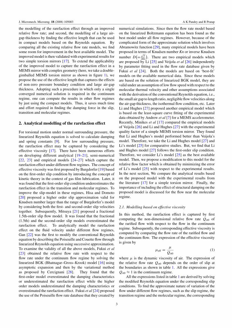
Figure 2. (a) Variation of the Abramowitz function of the zeroth, first and second orders at different Knudsen numbers; (b) comparison ofdifferent models of non-dimensional relative flow factor Qrt0 at different Knudsen numbers.
Table 1. Different analytical, semi-analytical and empirical models for considering the rarefaction effect.
Number Model Non-dimensional relative flow rate Qrt0
1 No slip 12 First-order slip [19] 1 + 6Kn3 Second-order slip [20] 1 + 3π/D + 3π/(2D2)
4 1.5th-order slip [21] 1 + 3π/D + 2π/(3D2)5 Linearized BGK model [23] 6f (D)/D, where f (D) is given by equation (2)6 Li’s model [25] 1 + 3a
√π/D + 6bDc,
where a = 0.018 07, b = 1.353 55, c = −1.174 687 Veijola’s model [26] 1 + 9.658Kn1.159
8 Li and Hughes’s model [27] 1 + 6.8636Kn0.9906
flow factors have also been obtained by solving the linearizedBoltzmann equation using semi-analytical approaches (seeFukui et al [23]). The flow factor based on the BGK model,which is the simplified form of the Boltzmann equation, isgiven by 6f (D)/D as mentioned in table 1. The expressionof f (D) is
f (D) = − 1
D+
1
�
(C11 − D2
6C12 +
D4
144C22
)(2)
where
C11 = 1√π
[8 −
√π
12D3 +
D4
16− 2D(4 + D2)T0(D)
−(
16 + 8D2 +D4
8
)T1(D) − D(16 + D2)T2(D)
],
C12 = 1√π
[2 −
√π
2D +
D2
4− 2DT0(D)
−(
4 +D2
2
)T1(D) − 2DT2(D)
],
C22 = 1√π
(1 − 2T1(D)) and � = C11C22 − C212.
Here Kn is the Knudsen number, D = √π/(2Kn) is the inverse
Knudsen number and Ti(D) is the Abramowitz function oforder i [29] which involves the integration of a function from0 to ∞. In order to numerically compute Ti(D), the upper limit∞ is replaced by M (a +ve integer) such that it gives minimum
error. Here, T0(D), T1(D) and T2(D) are solved numericallyusing MAPLE by taking a sufficiently high M instead of ∞.We take M = 10 for all the integrals as M > 6.5 gives an errorof less than 10−16 [33]. The values of all the three integralsare plotted in figure 2(a).
On comparing the first and higher order slip modelswith the Boltzmann solution, it is found that the first-ordermodel underestimates the rarefaction effect while the higherorder models overestimate it. To approximately capturethe rarefaction effects based on the solution of linearizedBoltzmann equation, Li [25] and Veijola et al [26] have foundthe approximate flow factors separately by fitting numericalsolutions. These two models are found to be useful because oftheir simple form unlike the form of the Boltzmann solutionwhich requires the solution of the zeroth-, the first- andthe second-order Abramowitz function. Later on, Li andHughes [27] found a separate empirical model by fitting theexperimental results reported in the literature. Their modelis slightly different from Veijola’s model in its form butdiffers substantially when its predicted values are comparedto Veijola’s and other models over the entire flow regime(see figure 2(b)). It is found that the Li and Hughes modelapproximately follows the variation of the first-order slipmodel which itself is questionable over the transition andmolecular flow regimes. By analysing different empirical andanalytical (based on the solution of BGK model) models, wefind the following limitations.
4

J. Micromech. Microeng. 18 (2008) 105003 A K Pandey and R Pratap
10-2
10 -1
100
101
102
103
102
103
104
105
106
Pressure (in Tor)
Qua
lity
fact
or
Exp. result (Minikes et al. )Li's modelProposed model
L=W=500 µm, h = 28 µm Frequency = 13.09 kHz
10-3
10 -2
10 -1
100
101
102
10310
1
102
103
104
105
106
Pressure (in Torr)
Qua
lity
fact
or
Exp. results (Minikes et al )Li's model Proposed model
L=W=500 µm, h = 13 µm Frequency = 13.09 kHz
10-3
10 -2
10 -1
100
101
102
10310
1
102
103
104
105
Pressure (in Torr)
Qua
lity
fact
or
h0 = 28 µ m
h0 =13 µ m
Cou
plin
g r
egio
n
Exp. result (Minikes et al. )Exp. result (Minikes et al. )
Li's model
(a) (b) (c)
Proposed model
Figure 3. Comparison of the analytical results for Qfluid based on Li’s model and the proposed model with the experimental quality factor[17] of a simple torsion mirror with air gap (a) h0 = 13 µm and (b) h0 = 28 µm. (c) Comparison of the net quality factor Qnet (here Qint isthe experimentally measured value) based on the present model with the experimental results over the entire flow regime.
• All models are valid for flows where compressibility andinertial effects are negligible. Therefore, the flow-rate-based BGK model gives finite error if these assumptionsare violated. Another source of error in the analyticalmodel is from the assumptions used in the approximationof the Boltzmann equation to get the BGK model. Sincethe models of Li [25] and Veijola et al [26] are based onthe numerical data from the BGK model, they also inheritthe same problems.
• Since the first-order slip model is valid for flows in theslip-regime, the solution based on the first-order slip isbound to give inaccurate results in the transition andmolecular regimes. Figure 2(b) clearly shows that thefirst-order model deviates from the BGK model near thetransition regime. Therefore, Li and Hughes model,which approximately follows the variation of the first-order slip model, cannot be taken as an accurate modelover the entire flow regime.
• When the surrounding pressure is reduced to the ultra-high vacuum (no-flow condition) or the high vacuum(molecular flow) condition, the damping is mainly due tothe internal structural losses. Such a regime is termed asintrinsic regime. However, there exists a coupling rangebetween the ultra-high and high vacuum conditions wherethe fluid damping and the structure-related damping arecomparable for high Q materials. Since the empiricalmodels derived from the numerical results assume thefluid damping as the dominant dissipation mechanism,they give large error when used in the coupling range.If Qfluid is the quality factor corresponding to the fluiddamping and Qint due to the non-fluid, internal dissipationmechanisms, the net quality factor of the system over theentire flow and the intrinsic regime is given by
1
Qnet= 1
Qfluid+
1
Qint. (3)
Note that the intrinsic damping is independent of thesurrounding pressure.
Since all the existing empirical models are based on fittingnumerical results or experimental results, they do not givegood results under all conditions. In other words, although the
models based on the numerical data follow correct variationwith respect to Kn, they give finite errors because of certainassumptions in analytical modelling. On the other hand, theempirical models based on fitting experimental results areappropriate only for a few cases. Therefore, in order toget the best model, the empirical model should be derivedperhaps by following a middle path in which it not only givescorrect variation with Kn but also fits well with experimentaldata. To do so, we choose Li’s model [25] which fits wellwith the numerical results obtained from the BGK model(simplified form of the Boltzmann equation) and followscorrect variation with Kn. In order to improve this model,we compare the analytical results and experimental resultsavailable in the literature and minimize the error with respectto the experimental results by fitting the best curve.
2.1.1. Simple torsion mirror. In this section, we take twodifferent simple mirrors of length 500 µm, width 500 µmand thickness 30 µm with different air-gap thicknesses h0 =13 µm and 28 µm, respectively [17]. For both cases, the airgap to length ratios, which are 0.026 and 0.056 respectively,are less than 0.1 and the corresponding squeeze numbers, 0.26and 0.05, are also less than 1. Therefore, we can use analyticalsolution obtained from the incompressible Reynolds equationfor the two mirrors. The resonance frequency of both themirrors is 13.09 kHz. When we compare the analytical resultsbased on Li’s model with the experimental results for thetwo cases in figure 3, we find that Li’s model overpredictsthe quality factor. In figures 3(a) and (b), the analyticallycomputed quality factor is based on the fluid damping, i.e.,Qfluid. By looking at the result, it is clear that Li’s modelcaptures the trend very well and hence is robust in its form.The values given by Li’s model, however, are off w.r.t. theexperimental results, and hence the model requires carefultweaking. From the form of the formula, we can see thatthe simplest change that gives us maximum leverage over theentire range is replacing the inverse Knudsen number D witha scaled number KD where K is a constant to be determined.Thus, we propose the following form of the relative flow rate:
Qrt0 = 1 + 3a
√π
KD+ 6b(KD)c (4)
5

J. Micromech. Microeng. 18 (2008) 105003 A K Pandey and R Pratap
0 100 200 300 400 500 600 7000
0.005
0.01
0.015
0.02
0.025
0.03
0.035
Frequency, f (in Hz)
Ang
ular
dis
plac
emen
t (in
rad
.)
Motion about x-axis (φ )
Motion about y -axis (θ)
fφ=260 Hz
fθ = 529.2 Hz
(c)
Fixed Substrate
h
φ
A-A' view
θ
Fixed Substrate
h
B-B' view
E3E4
E3 E2
b
aa
b
aa
bb
ttt t
(a)
(b)
zx
zy
pifof out
0
Figure 4. Sectional views (a) AA′ and (b) BB′ of the double-gimballed MEMS torsion mirror shown in figure 1(b). (c) Response of themirror about the x- and y-axes for the input voltage 20 ± 0.4 V.
where a = 0.018 07, b = 1.353 55, c = −1.174 68 and Kis a constant obtained by minimizing the error in the totalquality factor obtained from equation (3) with respect to theexperimental results considered. The minimization is doneusing the function ‘fminsearch’ in MATLAB. Based on thebest fit for the two cases h0 = 13 µm and 28 µm as shownin figure 3(c), the value of K is found to be 1.4. Thus, theproposed model for the relative flow rate factor is
Qrt0 = 1 + 3a
√π
1.4D+ 6b(1.4D)c. (5)
Now, on using this model of the relative flow rate, if wecompare the analytically obtained quality factor based onlyon fluid damping (i.e., Qfluid) with the experimental results infigures 3(a) and (b), we indeed find a very good match. Butlike the parent model, the proposed model is also limited toincompressible and non-inertial flows. From figures 3(a) and(b), we observe that the scaling factor K = 1.4 is independentof the air-gap thickness h for the case h/L < 0.1. Now, wecheck the validity of this model and see the dependence of Kon h, in a double-gimballed MEMS torsion mirror in which theratio of air-gap thickness h(= 80 µm) to length L(= 400 µm)is 0.2 (> 0.1).
Some comments regarding this factor K are in orderhere. Li’s model of the relative flow factor uses the inverseKnudsen number D ∼ h/λ as the main variable. Clearly,the characteristic flow length h is important here. While thislength scale is quite clear in the case of parallel plate motion,it is certainly different in the case of torsional motion. Theconstant K used in the proposed model is to take care of thischange in the characteristic length scale. One can perhapsthink of using a factor with h itself; however, it is cleaner toleave Kn as it is and use a constant to account for the changein it. This is the motivation behind using KD in the proposedmodel.
3. Semi-analytical modelling of the effects ofrarefaction and a large air-gap thickness
In this section, we compare the analytical results based on theproposed model and Li’s model [25] with the experimentalresults for a double-gimballed MEMS torsion mirror [30].The procedure of calculating the effective length of the double-gimballed rectangular torsion mirror is also described in detail.In addition, we also compare the analytical results based onthe free molecular dynamic model (based on the Maxwellianvelocity distribution) [18] with the experimental results withand without effective length of the mirror.
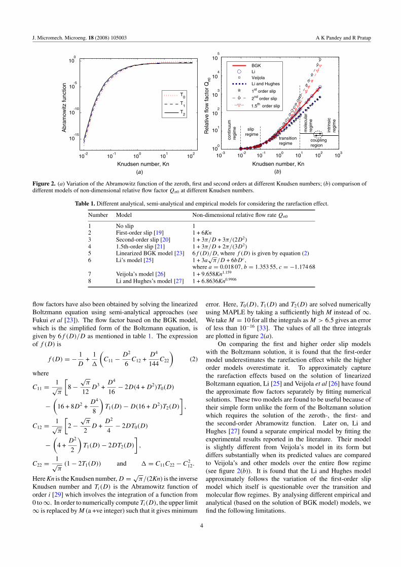
Here, we consider a double-gimballed MEMS torsionmirror as shown in figure 1. The different geometricdimensions of the mirror are shown in figure 1(b). The symbolsand the values of different dimensions are mentioned intable 2. The moments of inertia about the corresponding axesof motion are also mentioned in table 2.
Corresponding to an ambient pressure of 1.013 × 10⁵ Paand an air-gap thickness of 80 µm, the flow is underthe continuum regime. Under the continuum regime, thedifference in the frequency response of θ and φ correspondingto the motions about the x- and y-axes is shown in figures 4(a)and (b). The corresponding resonance frequencies are foundas
fθ = 529.2 Hz, fφ = 260 Hz (6)
while the corresponding quality factors under the continuumregime are QexpY = 9.19 ± 0.05 for the motion about the y-axis (i.e., θ motion) and QexpX = 2.35 ± 0.02 for the motionabout the x-axis (i.e., φ motion) [11, 30].
Since the maximum displacement amplitude at the edge ofthe oscillating structure corresponding to the peak response isabout 6 µm for the θ motion and 3 µm for the φ motion, we getthe ratio of the maximum oscillation amplitude to the air-gapthickness as 0.075 and 0.035, respectively. The correspondingsqueeze numbers are found to be 1.8 × 10⁻⁴ for θ motion and8.7 × 10−5 for φ motion with respect to the dimensions of the
6
J. Micromech. Microeng. 18 (2008) 105003 A K Pandey and R Pratap
Table 2. Dimensions of the MEMS torsion mirror shown in figure 1.
Symbol Description Values
lp Length of the inner plate 400 µmbp Width of the inner plate 400 µmtp Thickness of the inner plate 4.25 µmlif Length of the inner frame 778 µmbif Breadth of the inner frame 438 µmwif Width of the inner frame 52 µmtif Thickness of the inner frame 3.5 µmhw Gap between the inner plate and the inner frame 19 µmlin Length of the inner torsional bar 180 µmlout Length of the outer torsional bar 180 µmwin Width of the inner torsional bar 2 µmwout Width of the outer torsional bar 2 µmtin Thickness of the inner torsional bar 1.5 µmtout Thickness of the outer torsional bar 1.5 µmh0 Air-gap thickness 80 µma Inner side of the electrode from the central axis 10 µmb Outer side of the electrode from the central axis 170 µmρpoly Density of polysilicon 2300 kg m−3
Iθ Moment of inertia about the y-axis 2.106 × 10⁻¹⁷ kg m2
Iφ Moment of inertia about the x-axis 1.320 × 10⁻¹⁶ kg m2
G Shear modulus of polysilicon 6.5 × 10¹⁰ Pa
inner plate. Since the ratios of vibration amplitude and air-gap thickness are much smaller than 1 and squeeze numbersare also less than 1, the linearized, incompressible Reynoldsequation can be used in both the motions.
To analytically model the squeeze-film effect, we firstcompute the quality factor for the angular motions θ and φ
from the formula based on the linearized and incompressibleReynolds equation. Then, we find the effective length of anequivalent simple torsion mirror by comparing the values ofthe damping constants obtained from analytical formula andnumerical simulations (solution of the Navier Stokes equation)corresponding to the motion about both the axes.
3.1. Angular motion θ
In this case, only the inner plate oscillates with an angulardisplacement θ = θ0 sin ωθ t as shown in figure 4(a), where ωθ
is the angular frequency and t is the time. The maximum inputenergy Einput and the net energy loss Eloss are calculated from[31]
Einput = 1
2Iθ θ̇
2max = 1
2Iθθ
20 ω2
θ , (7)
Eloss =∫ 2π/ωθ
0Td θ̇ dt =
∫ 2π/ωθ
0Cθ θ̇
2 dt = πCθ θ20 ωθ (8)
where Td = Cθ θ̇, Iθ = 2.106 × 10⁻¹⁷ kg m2 and the angularfrequency ωθ = 2πfθ is based on the value of fθ = 529.2 Hzfrom equation (6). The squeeze-film damping constant Cθ dueto the incompressible squeeze flow in torsional motion is givenby [9]
Cθ = 192WL5µ
π6h30
m∑even
n∑odd
1
(mn)2(m2 + n2
(LW
)2) , (9)
where h0 = 80 µm is the air-gap thickness, L = 400 µm isthe length, W = 400 µm is the width of the inner rectangular
plate and µ is the air viscosity. Finally, the quality factor isdetermined from
Qθ = 2πEinput
Eloss= Iθωθ
Cθ
. (10)
Based on the geometric dimensions of the mirror, thequality factor is found to be 41.93 which is in error bymore than 300% with respect to the experimentally obtainedvalue. The higher percentage error in this case is due to thecomparable air-gap thickness to the lateral dimension, i.e.,h0/L = 0.2. To accommodate the effect of a large air-gapthickness, Veijola et al [14] have proposed to extend thesurfaces of a simple rectangular torsion mirror by 1.3h0 tofind the correct damping constant. From the damping constantbased on the extended length and width, the quality factor isfound to be 10.48 which differs by only 14% with respect tothe experimental value of 9.19.
3.2. Angular motion φ
Unlike the previous case, in this case, the system involves themotion of the inner plate and the inner frame as shown infigure 4(b). To find the damping constant, we note that someparts of the structure shown in figure 5(a) execute torsionalmotion and some parts execute almost transverse motion. Theinner plate and the longer arms of the outer frame (marked 2 infigure 5) execute torsional motion while the shorter arms of theouter frame (marked 3 in figure 5) undergo almost transversemotion.
We can, therefore, evaluate the squeeze-film damping byconsidering appropriate motion for these parts. The boundaryconditions here are certainly nontrivial. The gap between theinner mirror and the outer frame is not very big. This canpossibly lead to a non-zero pressure condition on the edgeof the mirror next to the outer frame. The length of such aboundary is small (only 25% of the total length of the outerframe) and the gap between the frame and the mirror is not
7

J. Micromech. Microeng. 18 (2008) 105003 A K Pandey and R Pratap
1 2
3
2
3
L1
LL2
W1
W2
LL3
Torsional part
1 22
Tor
sion
al
par
t
Tors
iona
l
par
t
3Transverse part
(a) (b)
Figure 5. (a) The schematic diagram of the structural part of the mirror (shown in figure 1) that is involved in the angular motion φ;(b) parts 1 and 2 execute torsional motion while part 3 undergoes transverse motion (arrows show fluid motion corresponding to thetransverse and torsional motions of the different parts of the oscillating structure).
so small (19 µm). Hence, for the first approximation, it isreasonable to ignore any complexity in flow arising from theinteraction of the two boundaries, particularly when the motionis torsional. Thus, we treat these boundaries independentlyand use a zero pressure condition in the flow calculations tofind damping. We get net damping by adding the individualcontributions.
If the whole structure oscillates with an angulardisplacement φ = φ0 sin ωφt , then the total input energy andthe losses due to the movement of parts 1, 2 and 3 are given by
Einput = 12Iφφ2
0ω2φ (11)
Eloss1 = πC1φ20ωφ, Eloss2 = 2 × πC2φ
20ωφ,
Eloss3 = 2 × πC3δ2ωφ (12)
where δ = φ0L2
2 , φ0 is the amplitude of angular oscillation,Iφ = 1.320 × 10⁻¹⁶ kg m2, the angular frequency ωφ iscalculated using fφ = 260 Hz from equation (6), C1 (L1 =400 µm, W1 = 400 µm) and C2 (L2 = 830 µm, W2 = 52 µm)are computed from equation (9) while C3 (L3 = 490 µm,W3 = 52 µm) is computed from the squeeze-film dampingformula due to transverse motion from [8]
C3 = 768W3L33µ
π6h30
m∑odd
n∑odd
1
(mn)2(m2 + n2
(L3W3
)2) . (13)
Finally, the net quality factor is computed from
Qφ = 2πEinput
Eloss= ωφIφ
C1 + 2C2 + 2C3L22
/4. (14)
The value of Qφ for the given structure with h0 = 80 µmcomes out to be 75.32, which differs from the experimentallyobtained value of 2.35 [30] by more than 3000%. Now, if weextend all the surfaces of dimensions (L1,W1), (L2,W2) and(L3,W3) by 1.3h0, then we get a much improved value of 4.44with an error of 89% w.r.t. the experimental value of 2.35.
The percentage errors in the quality factor in the twocases computed above are 14% and 89%, respectively, if allthe surfaces of the oscillating structures are extended by 1.3h0
for the computation of the damping constant C. Here, a largenumber of errors are introduced because of a large h0/L ratio0.2 for the inner plate (h0 = 80 µm and L = 400 µm) and1.53 for the inner frame (h0 = 80 µm and L = 52 µm). Since
(a) (b)
Leff
Weff
Equivalent Simple Mirror
(c)
yx
Figure 6. Pressure distribution due to the angular motion (a) θ and(b) φ; (c) an equivalent simple torsional mirror of length Leff andwidth Weff .
the factor 1.3h0 is based on a simple rectangular geometrywith fully open boundaries, a different extension factor χh0 isrequired here which can be found by comparing the analyticaldamping constant with the numerical result. The procedure forestimating the factor χ for both types of motions is discussedbelow.
3.3. Computation of the effective length based onnumerical results
We first compute the damping constant for the test structurewith original dimensions in both types of motion (i.e., φ and θ
about the x- and y-axes, respectively) by solving the Navier–Stokes equation in ANSYS [32]. Subsequently, we find theeffective length Leff = L+χh0 and the width Weff = W +χh0
of an equivalent simple torsion mirror as shown in figure 6(c)by comparing the analytical damping constant of the equivalentmirror from equation (9) with the numerical damping constant
8

J. Micromech. Microeng. 18 (2008) 105003 A K Pandey and R Pratap
of the original mirror. Here, we take the reference dimensionsL = 400 µm, W = 400 µm and h0 = 80 µm.
To numerically find the damping constant, we build a3D fluid domain in ANSYS around the vibrating structurein both cases. We extend the domain sufficiently from theside and top boundaries of the structure to accurately capturethe pressure distribution on the boundaries of the oscillatingstructure. Subsequently, we mesh the entire volume with 3Dtetrahedral fluid elements (FLUID 142). We solve the Navier–stokes equation to find the pressure distribution around themoving structure in the 3D domain as shown in figures 6(a)and (b). To compute the total back torque around the movingstructure, we integrate the moment of the back force aboutthe axis of oscillation over the entire surface. The convergedvalue of the net damping torque about the y-axis is found tobe Tθ = 1.0 × 10⁻¹³ N m corresponding to the sinusoidalangular displacement of amplitude θ0 = 4 × 10⁻³ rad and thefrequency of oscillation fθ = 529.2 Hz. The converged valuesof the damping torque corresponding to the motion about thex-axis is Tφ = 2.48 × 10⁻¹³ N m for an angular oscillation ofamplitude φ0 = 1.8 × 10⁻³ rad and frequency fφ = 260 Hz.Based on these values of damping torques Td , we computedamping constants from
Cnum = Td
ω, (15)
where is the amplitude of angular oscillations and ω isthe angular frequency. For the motion about the y-axis, wefind the damping constant to be 7.52 × 10⁻¹⁵ N s m−2 whilethat about the x-axis to be 8.43 × 10⁻¹⁴ N s m−2. Now, theeffective length and width of the equivalent simple torsionmirror are found by comparing the numerically computeddamping constant with the analytical value computed fromequation (9). On comparing, the extension factor, χ , for theinner plate dimensions is found to be 1.425 and 4.612 forthe motion about the y-axis (θ ) and that about the x-axis (φ),respectively. Finally, the effective length and width of thesquare plate are found to be 514 × 514 µm2 for the θ motion(about the y-axis) and 769 × 769 µm2 (about the x-axis) forthe φ motion. The corresponding quality factors are computedfrom
Q = Iω
Ceff. (16)
Here, the moment of inertia I (Iθ or Iφ) is computed fromthe original dimensions of the plate, the angular frequencyω(ωθ or ωφ) is taken from the measured value whereas thedamping constant Ceff is calculated from equation (9) bytaking the equivalent dimensions of the simple mirror asmentioned above. Based on the above procedure, the qualityfactor of the motions about the x- and y-axes are 2.57 and9.31. The percentage errors with respect to the correspondingexperimental results of 2.35 and 9.19 are now 9.36% and1.29%, respectively.
In this case, we have found the extension factors of 1.425and 4.612 for the two motions which are greater than the factor1.3 obtained by Veijola et al [14]. This is expected because thefactor 1.3 is for the rectangular structure with open boundaries.In the present case, the extension factor is increased because
of the nearby boundaries that affect the pressure boundarycondition of the plate. Although, the above procedure isused here for a rectangular structure, we see no reason why itcannot be used for finding the effective dimensions of otherdouble-gimballed mirror geometries, for example, a circularmirror. However, the procedure described here is limited toincompressible and non-inertial flows.
It is to be noted that the above analysis is done forthe flow under the continuum regime. To find the qualityfactor when the flow is rarified under the slip, transition andmolecular flow regimes, the required procedure is discussedin the next section. For this purpose, we take the above-mentioned equivalent length and width of a simple torsionalplate for calculating the damping constant for motions aboutboth the axes.
3.4. Modelling based on the effective viscosity approach
Here, we compare the analytical solution with the experimentalresults for the torsional motion about the x- and y-axes of thedouble-gimballed MEMS torsion mirror shown in figure 1.The resonance frequencies corresponding to two motions are260 Hz and 529 Hz. The geometric dimensions are given intable 2. The experimental quality factor at different pressuresfor the two motions are taken from [30]. In this case, theeffect of a large air gap (h0 = 80 µm) and rarefaction have tobe modelled simultaneously.
First, we compare the analytical result based on Li’s model[25] and the proposed model (using effective viscosity) withthe experimental results. We find that the analytical resultbased on equations (9), (10) and (1) for the y-axis motion(see figure 7(a)) and equations (11)–(14) and (1) for the x-axismotion (see figure 8(a)) underpredict the damping in bothtypes of motion when the original dimensions are used in thecalculations. It is because of a large h0/L ratio (0.2 > 0.1).To capture this effect, we have found the effective lengthand width of the equivalent mirror as 514 × 514 µm2 for θ
motion about the y-axis and 769 × 769 µm2 for φ motionabout the x-axis, while the other dimensions such as the platethickness and the air-gap thickness are kept the same as theactual values. Now, we again compare the results for thetwo motions by taking the corresponding effective dimensionsand Li’s model to capture the large air gap to length ratioand rarefaction effects in figures 7(a) and 8(b). We findthat Li’s model [25], which is valid for arbitrary Knudsennumber, overpredicts the quality factor in the transition andmolecular regimes. This overprediction is due to the inherenterrors in the fitting parameters. However, when we use theimproved model from equation (5) in figures 7 and 8, we notethat while the modified model improves over the previousmodel in the slip and transition regimes, it still overpredictsthe quality factor in the molecular regime. Since the non-fluiddamping (i.e., structure-related losses) become comparable tothe fluid damping in the molecular regime, its contribution tothe net damping cannot be neglected. This is probably theonly obvious reason for large quality factor predicted by themodified model which was also observed in the case of simplemirror results shown in figure 3.
9

J. Micromech. Microeng. 18 (2008) 105003 A K Pandey and R Pratap
10-3
10-2
10-1
100
101
102
10310
0
101
102
103
104
105
106
Pressure (in T orr)
Qua
lity
fact
or
Frequency = 529.2 Hz
(a) (b)
10-4
10-2
100
10210
0
102
104
106
108
Pressure (in T orr)
Qua
lity
fact
or
Exp. result(φ)(φ)(φ)
Without struc. dampWith struc. damp
1X10⁴
Transitionregime
Slip
regi
me
Con
tinuu
mre
gim
e
Molecularregime
Couplingregion
Intr
insi
cre
gim
e
Exp. result (φ about y-axis)Li’s formula (Original dims.)Li ’s formula (Effective dims.)Proposed model (Original dims.)
h = 80 µm
Frequency = 529.2 Hz
h = 80 µm
Proposed model (Effective dims.)
Figure 7. Comparison of the analytical result based on Li’s model and the present model with the experimental quality factor for the angularmotion θ of the double-gimballed MEMS torsion mirror as shown in figure 1. (b) Prediction of the structural quality factor based on thecoupling effect of structural damping and fluid damping.
(a) (b)
10-3
10-2
10-1
100
101
102
10310
0
101
102
103
104
105
106
107
Pressure (in T orr)
Qua
lity
fact
or
Exp. result(φ about x-axis)Li’s formula (Original dimensions)
Li ’s formula (Effective dimensions)
Proposed model (Org. dims.)
Frequency = 260 Hz
10-4
10-2
100
10210
0
102
104
106
108
Pressure (in T orr)
Qua
lity
f act
or
Exp. result(φ)
(θ)(θ)Without struc. damp
With struc. damp
6X10³
Transitionregime
S
lipre
gim
e
Con
tinuu
mr e
gim
e
Molecularregime
Couplingregion
Intr
insi
cr e
gim
e
h = 80 µm
h = 80 µmFrequency = 260 Hz
Proposed model (Effect. dims.)
Figure 8. Comparison of the analytical result based on Li’s model and the present model with the experimental quality factor for the angularmotion φ of the double-gimballed MEMS torsion mirror as shown in figure 1. (b) Prediction of the structural quality factor based on thecoupling effect of structural damping and fluid damping.
Now, considering the coupling effect of the non-fluiddamping in the present structure (see figures 7(b) and 8(b)), ifwe use equation (3) to find the net quality factor which couplesthe structural and fluid effects, we find that the structuralquality factor Qint(1/Qint = 1/Qtot − 1/Qfluid) for the motionabout the y-axis is approximately 1×10⁴ and that about the x-axis is 6×10³. Although, the internal damping in the torsionalmotion is said to be dominated by the support losses [34],the source of internal damping in the present structure is notwell known. Further investigations are required to explorethe possibility of finding the correct structure-related lossmechanism in the present device. Here, we have limited ourinvestigation to fluid-flow-related losses. We also must pointout that the modified relative flow rate works well even for alarge h0/L ratio of 0.2. Therefore, we think that the scalingfactor K in the proposed relative flow rate is independent ofthe gap thickness as long as the other assumed flow conditionsare met.
3.5. Modelling based on the free molecular model
Alternatively, the quality factor of the torsion mirror inthe molecular flow regime can be obtained from moleculardynamic simulation (MDS) [16]. Since performing MDSfor a large number of molecules requires high-performancecomputing and long simulation time, Bao et al [18] derivedthe expression for quality factor by assuming the constantMaxwell velocity distribution for each molecule in the puretransverse motion. Later Minikes et al [17] applied the sameformula to the torsional structure by assuming the two halvesof the mirror executing the out-of-phase transverse motion.The expression for the quality factor is given by
QBao = (2π)3/2ρstpωh0
PR
√RT
Mair
1
p(17)
where ρs = 2300 kg m−3 is the density of polysilicon,tp = 4.25 µm is the plate thickness, ω = 2πf is the angular
10

J. Micromech. Microeng. 18 (2008) 105003 A K Pandey and R Pratap
10-3 10-2 10-1
100
101
102
103
100
101
102
103
104
105
Experimental results (
Bao’ s model (Original dims.)
Bao’ s model (Effective dims.)
Pressure (in T orr)
Qua
lity
fact
or
Pressure (in T orr)
Qua
lity
fact
or
)
Frequency = 529.2 Hz
(a) (b)
φ
10-3
10 10 100
101
102
103
10-1
100
101
102
103
104
Experimental results ( )
Bao’s model (actual dims.)
Bao’s model (effective dims.)
θ
Frequency = 260 Hz
-2 -1
Figure 9. Comparison of Bao’s molecular model (based on the original and the effective length and width) with the experimental resultcorresponding to the angular motion of (a) θ and (b) φ.
frequency, f is the excitation frequency which is equal to529 Hz for the motion about the y-axis and 260 Hz for themotion about the x-axis, h0 = 80 µm is the air-gap thickness,PR is the total peripheral length which is equal to (2L + 2W)
(see [18]) for the transverse motion and (2L + 4W) (see[17]) for the torsional motion, where L (here, the length Lis the lateral dimension perpendicular to the axis of rotation)and W are the length and width of the rectangular plate,R = 8.314 J kg−1 K−1 is the universal gas constant, Mair =28.92 × 10⁻³ kg m−3 is the molar mass of the air and p (in Pa)is the surrounding pressure.
In our study, since the geometry of the oscillating structureis complex, we use the effective length and width for θ andφ motions separately. Here, equation (17) is used with theeffective length Leff and the width Weff so that the peripherallength becomes (2Leff + 4Weff). For the motions about they-axis and the x-axis, the peripheral length PR is 3084 µmand 4614 µm, respectively. The corresponding values of thequality factor in the two cases are shown in figures 9(a) and(b). The analytical results from Bao’s model based on originaldimensions are also compared. It is found that for θ theanalytical results based on original dimensions perform betterthan that based on the effective length. Nevertheless, both areclose to the experimental values. On the other hand, for the φ
motion in which different parts of the structure have differenttypes of motion as described in section 3.2, the results based oneffective dimensions perform better than that based on originaldimensions if compared with the experimental results. But themost significant point is that when we observe the analyticalresults based on Bao’s model in figure 9 and that based onthe effective viscosity approach in figures 7 and 8, Bao’smodel performs better than the effective viscosity approacheven with original dimensions. This may be due to the factthat in the molecular regime the constant velocity assumptionand ignoring intermolecular collisions in Bao’s model holdgood. Therefore, it is found that Bao’s model can be usedeven for an air gap to length ratio of 0.2, and for complexgeometry one can use the effective length concept to computethe quality factor.
In closing, we point out that the coupling of effectiveviscosity and effective length has proved to be a usefulapproach to capture the effects of rarefaction and a large airgap to length ratio.
4. Conclusion
We have analysed damping in a double-gimballed torsionalmirror that presents difficulties in using analytical modelson two counts—a large air gap to plate length ratio andcomplicated boundary conditions. We have found that we canstill compute the effective length and width of an equivalentsimple torsional mirror with simple boundary conditions basedon numerical simulations and use the effective dimensionsin the analytical model to predict damping correctly in thecontinuum regime. To capture the effect of rarefaction over alarge range covering the slip, transition and molecular regimesof flow, we have proposed a modified version of Li’s modelfor computing the relative flow factor. The modification isbased on a set of experimental results. The modified modelis then validated against another set of experimental resultsand shown to be effective over the entire flow range. We haveshown that the proposed model also couples very well withinternal losses in the intrinsic regime.
Acknowledgments
This study is supported by the Department of Science andTechnology (DST), New Delhi, India. The authors wish tothank Professor F S Chau of National University of Singaporefor providing support for experimental measurements on thetorsional mirror. The first author is also grateful to the LadyDavis Foundation at the Technion for supporting him by apostdoctoral fellowship.
References
[1] Walker J A 2000 The future of MEMS in telecommunicationsnetworks J. Micromech. Microeng. 10 R1–7
11

J. Micromech. Microeng. 18 (2008) 105003 A K Pandey and R Pratap
[2] Zhou G, Tay F E H and Chau F S 2003 Macro-modelling of adouble-gimbaled electrostatic torsional micromirrorJ. Micromech. Microeng. 13 532–47
[3] Toshiyoshi H and Fujita H 1996 Electrostatic micro torsionmirrors for an optical switch matrix IEEE J.Microelectromech. Syst. 5 231–7
[4] Chung S W, Shin J W, Kim Y K and Han B S 1996 Designand fabrication of micromirror supported by electroplatednickel posts Sensors Actuators A 54 464–7
[5] Yang J, Ono T and Esashi M 2002 Energy dissipation insubmicrometer thick single-crystal silicon cantileversJ. Microelectromech. Syst. 11 775–83
[6] Hosaka H, Itao K and Kuroda S 1995 Damping characteristicsof beam-shaped micro-oscillators Sensors Actuators A49 87–95
[7] Andrews M K, Harris I and Turner G 1993 A comparison ofsqueeze-film theory with measurements on a microstructureSensors Actuators A 36 79–87
[8] Blech J J 1983 On isothermal squeeze films J. Lubr. Technol.105 615–20
[9] Pan F, Kubby J, Peeters E, Tran A T and Mukherjee S 1998Squeeze film damping effect on the dynamic response of aMEMS torsion mirror J. Micromech. Microeng. 8 200–8
[10] Pinkus O and Sternlicht B 1961 Theory of HydrodynamicLubrication (New York: McGraw-Hill)
[11] Pandey A K, Pratap R and Chau F S 2007 Influence ofboundary conditions on the dynamic characteristics ofsqueeze-film in MEMS devices J. Microelectromech. Syst.16 893–903
[12] Hung E S and Senturia S D 1999 Generating efficientdynamical models for microelectromechanical systemsfrom a few finite-element simulation runsJ. Microelectromech. Syst. 8 280–9
[13] Vemuri S, Fedder G K and Mukherjee T 2000 Low-order squeeze film model for simulation of MEMS devicesProc. 3rd Int. Conf. on Modelling and Simulation ofMicrosystems
[14] Veijola T, Pursula A and Raback P 2005 Extending the validityof squeezed-film damper models with elongations ofsurface dimensions J. Micromech. Microeng.15 1624–36
[15] Hao Z, Clark R, Hammer J, Whitley M and Wingfield B 2002Modeling air-damping effect in a bulk micromachined 2Dtilt mirror Sensors Actuators A 102 42–8
[16] Bird G A 1996 Molecular Gas Dynamics and the DirectSimulation of Gas Flows (Oxford: Oxford University Press)
[17] Minikes A, Bucher I and Avivi G 2005 Damping of amicro-resonator torsion mirror in rarefied gas ambientJ. Micromech. Microeng. 15 1762–9
[18] Bao M, Yang H, Yin H and Sun Y 2002 Energy transfer modelfor squeeze-film air damping in low vacuum J. Micromech.Microeng. 12 341–6
[19] Burgdorfer A 1959 The influence of the molecular mean freepath on the performance of hydrodynamic gas lubricationbearings ASME J. Basic Eng. 81 94–100
[20] Hisa Y T and Domoto G A 1983 An experimentalinvestigation of molecular rarefaction effects in gaslubricated bearings ASME J. Lubr. Technol. 117 120–30
[21] Mitsuya Y 1993 Modified Reynolds equation for ultra-thinfilm gas lubrication using 1.5-order slip-flow model andconsidering surface accommodation coefficients ASME J.Tribol. 115 289–94
[22] Gans R F 1985 Lubrication theory at arbitrary Knudsennumber J. Tribol. 107 431–3
[23] Fukui S and Kaneko R 1988 Analysis of ultra-thin gas filmlubrication based on linearized Boltzmann equation: firstreport derivation of a generalized lubrication equationincluding thermal creep flow J. Tribol. 110 253–62
[24] Fukui S and Kaneko R 1990 A database for interpolation ofPoiseuille flow rates for high Knudsen number lubricationproblems J. Tribol. 112 78–83
[25] Li W-L 1999 Analytical modelling of ultra-thin gas squeezefilm Nanotechnology 10 440–6
[26] Veijola T, Kuisma H, Lahdenpera J and Ryhanen T 1995Equivalent-circuit model of the squeezed gas film in asilicon accelerometer Sensors Actuators A 48 239–48
[27] Li G and Hughes H 2000 Review of viscosity damping inmicro-machined structures Proc. SPIE 4176 30–46
[28] Cercignani C and Pagani C D 1966 Variational approach toboundary-value problems in kinetic theory The Phys. Fluid9 1167–73
[29] Abramowitz M and Stegun I A 1965 Handbook ofMathematical Functions with Formulas, Graphs, andMathematical Tables (New York: Dover)
[30] Pandey A K, Pratap R and Chau F S 2008 Effect of pressure onfluid damping in MEMS torsional resonators with flowranging from continuum to molecular regime Exp. Mech.48 91–106
[31] Rao S S 1995 Mechanical Vibration (New York: Wesley)[32] ANSYS 10—Finite Element Solver for Multiphysics Problems
http://www.ansys.com[33] Buscaglia G C and Jai M 2004 Homogenization of the
generalized Reynolds equation for ultra-thin gas films andits resolution by FEM J. Tribol. 126 547–52
[34] Judge J A, Photiadis D M, Vignola J F, Houston B H andJarzynski J 2007 Attachment loss of micromechanical andnanomechanical resonators in the limits of thick and thinsupport structures J. Appl. Phys. 101 013521
12