A robotic system for underwater eco-sustainable wire-cutting · PDF fileA robotic system for...
11
A robotic system for underwater eco-sustainable wire-cutting Rezia M. Molfino ⁎, Matteo Zoppi University of Genoa, PMAR Robotics, via Opera Pia 15A, 16145 Genoa, Italy abstract article info Article history: Accepted 9 March 2012 Available online 6 April 2012 Keywords: Cutting technology Diamond wire Marine structures Underwater robotics The paper deals with the design and development of a diamond wire cutting system used as end-effector of an underwater robot for removal of offshore constructions. This system fulfills the sea-bottom reclamation duties required by the environmental protection acts related to dismissing of off-shore oil plants. The re- search results have been achieved through extensive interaction between academia and industry, which have solved jointly scientific, technological, economic and social issues along the challenging track to eco- consistency. The, study brings forth: – the analysis of cutting using a diamond wire saw to accomplish the conceptual design of the system; – the wire micro analysis to select a suitable wire configuration. The topics are summarized highlighting the design steps, including preliminary life-cycle assessments accomplished by joining virtual reality tests and trials on an experimental bench. The robotic system has been realized and it is working satisfactory in the North Sea. © 2012 Elsevier B.V. All rights reserved. 1. Introduction The conventional cutting technologies in use for sub-sea struc- tures, in particular explosives and high-pressure water-jet cutting, disseminate large quantities of pollutants in the sea during the cut- ting and dismantling process [1–5]. Explosives, especially, brake and disseminate layers of oily mud and drilling residuals stratified in the surroundings of the drilling rig and project fragments are difficult to collect in a wide area. The change in regulation in the last 10 years practically banned these conventional techniques making urgent the need for effective alternatives. In particular, it was required that, at the end of the dis- mantling, the seabed was free of any residual structure up to 5 m below the sea-bed surface. The cutting system presented in the paper was developed in re- sponse to these changes in regulations and increasing green atten- tion. It consists of a tool operated by an underwater robot forming a system able to excavate the sea bed soil limiting the volume of the sea-bed materials interested by the excavation; the underwater structures are then cut using diamond wire technology down to 5 m below the sea bottom soil (Fig. 1). Task details can be found in [6–9]. The objectives and key advantages of the selected scientific and technological approach also in comparison to other technologies are: • the use of a clean technology not interfering with the equilibrium of the marine habitat; • the absolute certainty to complete the cutting task (unsure with the alternative cutting technologies); • the optimization in terms of energy, environmental impact, opera- tional efficiency, reliability, diamond wire consumption; • the automation of the complex tasks involved in the dismantling op- erations with an “intelligent” remote control/drive station at surface; • the integrated design of mechanics, hydraulics and the underwater functional components (sensors, electro-hydraulics, data system); • the unaltered functionality of the portions of structures removed making possible their re-use (impossible with other cutting tech- niques which cause extensive damages during removal). The originality of the new system relies in combining and improv- ing known and cooperating technologies, namely: diamond wire cut- ting and sub-bottom operation with robot-based tools and remote monitoring and control [8,9]. This leads to the unique and never attempted task of shearing below the seabed in a hostile environment with a low-impact duty-scheme (dig-and-saw) through a reliable and safe process (unmanned work-cycles). The design process took advantage from different kinds of virtual prototyping and simulation techniques [10] that allowed the valida- tion of the analyzed solutions at the subsequent design stages, as de- cision support and performance verification. Automation in Construction 24 (2012) 213–223 ⁎ Corresponding author. Tel.: + 39 010 353 2842; fax: + 39 010 353 2298. E-mail addresses: molfi[email protected] (R.M. Molfino), [email protected] (M. Zoppi). 0926-5805/$ – see front matter © 2012 Elsevier B.V. All rights reserved. doi:10.1016/j.autcon.2012.03.005 Contents lists available at SciVerse ScienceDirect Automation in Construction journal homepage: www.elsevier.com/locate/autcon
Transcript of A robotic system for underwater eco-sustainable wire-cutting · PDF fileA robotic system for...

Automation in Construction 24 (2012) 213–223
Contents lists available at SciVerse ScienceDirect
Automation in Construction
j ourna l homepage: www.e lsev ie r .com/ locate /autcon
A robotic system for underwater eco-sustainable wire-cutting
Rezia M. Molfino ⁎, Matteo ZoppiUniversity of Genoa, PMAR Robotics, via Opera Pia 15A, 16145 Genoa, Italy
⁎ Corresponding author. Tel.: +39 010 353 2842; faxE-mail addresses: [email protected] (R.M. Mol
(M. Zoppi).
0926-5805/$ – see front matter © 2012 Elsevier B.V. Alldoi:10.1016/j.autcon.2012.03.005
a b s t r a c t
a r t i c l e i n f oArticle history:Accepted 9 March 2012Available online 6 April 2012
Keywords:Cutting technologyDiamond wireMarine structuresUnderwater robotics
The paper deals with the design and development of a diamond wire cutting system used as end-effector ofan underwater robot for removal of offshore constructions. This system fulfills the sea-bottom reclamationduties required by the environmental protection acts related to dismissing of off-shore oil plants. The re-search results have been achieved through extensive interaction between academia and industry, whichhave solved jointly scientific, technological, economic and social issues along the challenging track to eco-consistency. The, study brings forth: – the analysis of cutting using a diamond wire saw to accomplish theconceptual design of the system; – the wire micro analysis to select a suitable wire configuration. The topicsare summarized highlighting the design steps, including preliminary life-cycle assessments accomplished byjoining virtual reality tests and trials on an experimental bench. The robotic system has been realized and it isworking satisfactory in the North Sea.
© 2012 Elsevier B.V. All rights reserved.
1. Introduction
The conventional cutting technologies in use for sub-sea struc-tures, in particular explosives and high-pressure water-jet cutting,disseminate large quantities of pollutants in the sea during the cut-ting and dismantling process [1–5]. Explosives, especially, brake anddisseminate layers of oily mud and drilling residuals stratified in thesurroundings of the drilling rig and project fragments are difficult tocollect in a wide area.
The change in regulation in the last 10 years practically bannedthese conventional techniques making urgent the need for effectivealternatives. In particular, it was required that, at the end of the dis-mantling, the seabed was free of any residual structure up to 5 mbelow the sea-bed surface.
The cutting system presented in the paper was developed in re-sponse to these changes in regulations and increasing green atten-tion. It consists of a tool operated by an underwater robot forminga system able to excavate the sea bed soil limiting the volume ofthe sea-bed materials interested by the excavation; the underwaterstructures are then cut using diamond wire technology down to5 m below the sea bottom soil (Fig. 1). Task details can be found in[6–9].
: +39 010 353 2298.fino), [email protected]
rights reserved.
The objectives and key advantages of the selected scientific andtechnological approach also in comparison to other technologies are:
• the use of a clean technology not interfering with the equilibrium ofthe marine habitat;
• the absolute certainty to complete the cutting task (unsure with thealternative cutting technologies);
• the optimization in terms of energy, environmental impact, opera-tional efficiency, reliability, diamond wire consumption;
• the automation of the complex tasks involved in the dismantling op-erations with an “intelligent” remote control/drive station at surface;
• the integrated design of mechanics, hydraulics and the underwaterfunctional components (sensors, electro-hydraulics, data system);
• the unaltered functionality of the portions of structures removedmaking possible their re-use (impossible with other cutting tech-niques which cause extensive damages during removal).
The originality of the new system relies in combining and improv-ing known and cooperating technologies, namely: diamond wire cut-ting and sub-bottom operation with robot-based tools and remotemonitoring and control [8,9]. This leads to the unique and neverattempted task of shearing below the seabed in a hostile environmentwith a low-impact duty-scheme (dig-and-saw) through a reliable andsafe process (unmanned work-cycles).
The design process took advantage from different kinds of virtualprototyping and simulation techniques [10] that allowed the valida-tion of the analyzed solutions at the subsequent design stages, as de-cision support and performance verification.

Fig. 1. The robot platform.
Fig. 2. Configuration of the cutting end-effector.
214 R.M. Molfino, M. Zoppi / Automation in Construction 24 (2012) 213–223
The following sections are dedicated to the description of the cut-ting systemmacromodel and design and to the wire micro model andsimulation. The fourth section presents the features of the monitoringand control system. The last section is devoted to field experimentaltrials with the robotic system prototype.
2. The cutting end-effector
The robot arm comprises two pipes mounted on a slider. A drillinghead is present at the free end of each pipe: when activated, they ex-cavate the soil in front of the pipes and the slider can be pushed intothe seabed. Two smaller sliders, one per pipe, carry a system of pul-leys which tension and run the diamond wire between the pipes.The wire translates along the pipes cutting any body placed in themiddle of the pipes.
The success of the remotely operated robotic platform highly de-pends on the effectiveness and reliability of the diamond wire cuttingprocess. This suggested to deepen the knowledge on the processfor typical off-shore structures and on the progression of the wearof wire and beads. A cutting operation cannot be resumed if stoppedand the wire must not break during a cut: it is then extremely impor-tant to predict the life of the wire.
The study moved in three directions: requirements on arrange-ment and operative conditions of the wire; adaptation of the wirearchitecture to materials cut and cutting conditions; beads life predic-tion by understanding the local properties of the diamond cut action.
To study the wire arrangement and operative conditions, a multi-body model of diamond wire loop running on pulleys has been imple-mented as shown in Fig. 2. The model takes into account the motionof the cutting system along the pipes and the presence and operationof tensioners.
Sealers and a system of water jets clean the wire preventing itfrom dragging soil inside the pipes when the wire reaches the seabed.To increase cutting reliability and have higher wire pull and cuttingrate, a new concept diamond wire string has been studied andadopted.
The adaptation to materials and cutting conditions has shownpossible and recommendable to maximize cutting rate and wire lifeprediction.
Beads life prediction has progressed distinguishing the criticalfactors into:
• structural properties: bead shaping, diamond laying deposition,diamond size and distribution, metal bond and toughness;
• operation conditions: cutting speed and pressure, cable stretch,diamond crystal fragmentation and edges wear as function of dutyparameters.
In the following the models used for defining the new cutting end-effector are briefly introduced.
3. Diamond wire macro analysis
3.1. Wire feeding mechanism
The wire axial tension is a relevant parameter related to wire lifeand cutting rate. It has been studied using simplified analytic-numerical models implemented in Maple using, as reference, asimplified cutting device equipped with one motorized pulley, asillustrated in Fig. 2. The tension is calculated along the wire and ateach pulley.
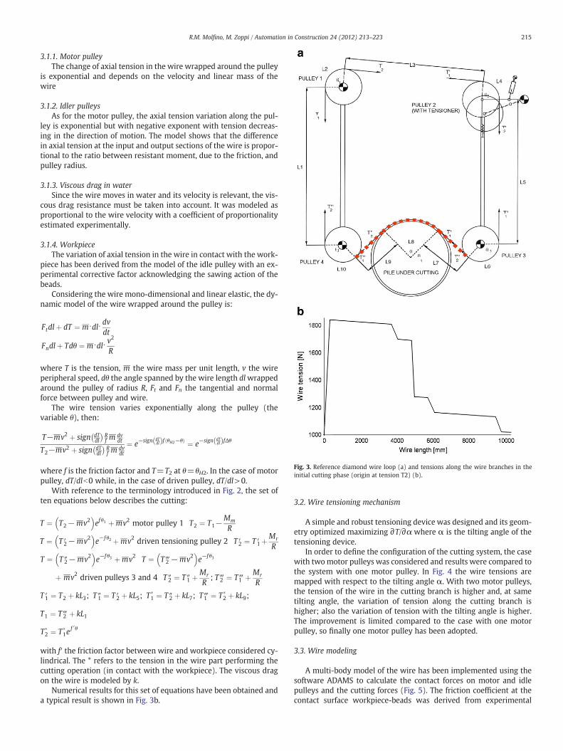
Fig. 3. Reference diamond wire loop (a) and tensions along the wire branches in theinitial cutting phase (origin at tension T2) (b).
215R.M. Molfino, M. Zoppi / Automation in Construction 24 (2012) 213–223
3.1.1. Motor pulleyThe change of axial tension in the wire wrapped around the pulley
is exponential and depends on the velocity and linear mass of thewire
3.1.2. Idler pulleysAs for the motor pulley, the axial tension variation along the pul-
ley is exponential but with negative exponent with tension decreas-ing in the direction of motion. The model shows that the differencein axial tension at the input and output sections of the wire is propor-tional to the ratio between resistant moment, due to the friction, andpulley radius.
3.1.3. Viscous drag in waterSince the wire moves in water and its velocity is relevant, the vis-
cous drag resistance must be taken into account. It was modeled asproportional to the wire velocity with a coefficient of proportionalityestimated experimentally.
3.1.4. WorkpieceThe variation of axial tension in the wire in contact with the work-
piece has been derived from the model of the idle pulley with an ex-perimental corrective factor acknowledging the sawing action of thebeads.
Considering the wire mono-dimensional and linear elastic, the dy-namic model of the wire wrapped around the pulley is:
Ftdlþ dT ¼ m⋅dl⋅ dvdt
Fndlþ Tdθ ¼ m⋅dl⋅ v2
R
where T is the tension, m the wire mass per unit length, v the wireperipheral speed, dθ the angle spanned by the wire length dlwrappedaround the pulley of radius R, Ft and Fn the tangential and normalforce between pulley and wire.
The wire tension varies exponentially along the pulley (thevariable θ), then:
T−mv2 þ sign dTdl
� �Rf m
dvdt
T2−mv2 þ sign dTdl
� �Rf m
dvdt
¼ e−sign dTdlð Þf θH2−θð Þ ¼ e−sign dT
dlð ÞfΔθ
where f is the friction factor and T=T2 at θ=θH2. In the case of motorpulley, dT/dlb0 while, in the case of driven pulley, dT/dl>0.
With reference to the terminology introduced in Fig. 2, the set often equations below describes the cutting:
T ¼ T2−mv2� �
ef θ1 þmv2 motor pulley 1 T2 ¼ T1−Mm
R
T ¼ T ′2−mv2� �
e−f θ2 þmv2 driven tensioning pulley 2 T ′2 ¼ T ′1þMr
R
T ¼ T ″2−mv2� �
e−f θ3 þmv2 T ¼ T‴2 −mv2� �
e−fθ3
þ mv2 driven pulleys 3 and 4 T ″2 ¼ T ″1 þMr
R; T‴2 ¼ T‴1 þMr
R
T ′1 ¼ T2 þ kL3; T ″1 ¼ T ′2 þ kL5; T�1 ¼ T ″2 þ kL7; T‴1 ¼ T�
2 þ kL9;
T1 ¼ T‴2 þ kL1
T�2 ¼ T�
1ef 0θ
with f′ the friction factor between wire and workpiece considered cy-lindrical. The * refers to the tension in the wire part performing thecutting operation (in contact with the workpiece). The viscous dragon the wire is modeled by k.
Numerical results for this set of equations have been obtained anda typical result is shown in Fig. 3b.
3.2. Wire tensioning mechanism
A simple and robust tensioning device was designed and its geom-etry optimized maximizing ∂T/∂α where α is the tilting angle of thetensioning device.
In order to define the configuration of the cutting system, the casewith twomotor pulleys was considered and results were compared tothe system with one motor pulley. In Fig. 4 the wire tensions aremapped with respect to the tilting angle α. With two motor pulleys,the tension of the wire in the cutting branch is higher and, at sametilting angle, the variation of tension along the cutting branch ishigher; also the variation of tension with the tilting angle is higher.The improvement is limited compared to the case with one motorpulley, so finally one motor pulley has been adopted.
3.3. Wire modeling
A multi-body model of the wire has been implemented using thesoftware ADAMS to calculate the contact forces on motor and idlepulleys and the cutting forces (Fig. 5). The friction coefficient at thecontact surface workpiece-beads was derived from experimental

Fig. 4. Wire tensions versus tensioning device tilt angle [rad].
216 R.M. Molfino, M. Zoppi / Automation in Construction 24 (2012) 213–223
tests with different geometries of the workpiece and different cuttingspeeds. The wire (Fig. 6a) is modeled as a chain of rigid bodies repre-senting the beads and the wire, connected by rotational joints withflexural stiffness and dumping.
A branch of the wire, constrained at the two ends, is a continuoussystem with infinite vibration modes and frequencies. The onlymodes of interest are the ones close to the forcing frequencyνforcing ¼ Vwire
S where S is the spacing of the beads and V the velocityof the wire.
The wire wave model:
μ∂2θ∂2t
−F∂2θ∂2x
¼ 0
solved considering the wire constraints is:
θ x; tð Þ ¼ θmax sinnπl11
x� ��
cosffiffiffiffiffiffiF�μ
q nπl11
t� �
where θ is the vibration amplitude, l11 the wire length (see the sketchin Fig. 2), n an integer corresponding to the actual mode, F the appliedforce and μ the wire mass per unit length. The stationary mechanicalwaves are described as sinusoidal.
The model has been firstly tuned (values for torsion springs anddumpers) to get the same behavior as the real wire under bendingand during free oscillations (measured during physical tests). Anintermediate model implemented in the software Pro/MechanicaMotion by PTC has been also used in combination with the ADAMSmodel (Fig. 6b). After this first calibration, a set of simulations hasbeen run calculating the contact forces between single beads andworkpiece during cutting.
Fig. 7 shows the magnitudes of the contact forces between fourfollowing beads (numbered 37, 38, 39 and 40) and the workpiece,for one of the cases solved with model fully tuned. The contact be-tween bead 37 and the workpiece starts at time 0.01 s and the reac-tion force rises till to time 0.03 s when bead 38 contacts theworkpiece. At this instant bead 37 oscillates and stabilizes at a forceof about 800 N. The bead receives a final strong pulse before
Fig. 5. Contact pressure distribution along the cutting area.
detaching from the workpiece. This trend is common to all otherbeads. The distribution of the contact force vectors obtained isshown in Fig. 6b.
4. Cutting microscopic analysis
4.1. Diamond cutting mechanism and modeling
Each bead can be assimilated to a grindstone with a semi-cylindrical working surface that moves forward along a rectilineartrajectory [11], Fig. 8.
Angles and size of the grain do not have definite values but can beconsidered probabilistic variables. Generally, the superior draft angleis negative up to −50°, and, consequently, the angle Φ locating theplastic zone is rather small.
The direction of the cutting force spans a wide angle, Ω, with thedirection of the wire especially when the contact pressure betweenwire and workpiece is high. Considering the distance betweenbeads, the ideal shaving (chip) section results very small as well,with shape coefficient rather high. All these elements contribute toincrease the cutting pressure increasing the share of mechanicalenergy converted in heat.
Most of the heat is generated by the rear face of the crystal thatcrawls on the work-piece because of its small inclination. Since theoperation is performed underwater, the temperature of the cuttingsurfaces keeps low compared to usual cutting temperatures in air-moisture and the removal of shavings from the cutting zone proceedsregularly and efficiently.
The grinding process of the diamond wire can be schematicallydescribed as a sequence of short trajectories of each bead duringwhich the bead is in contact with the workpiece. When contactingthe workpiece, a subset of the diamond grains on the bead performsthe cutting. As time goes by, the cutting edges, and the metal matrixas well, wear out. Gradually the crystals break according to the cleav-age surfaces or are completely removed from the matrix.
Critical collisions between the bead flank and the work-piece hap-pen when the cutting wire works on sharp corners as shown in Fig. 8:the wire bends over a certain angle, the spacing spring between con-secutive beads crawls on the edge and the collision between bead andcorner may damage the bead body.
Such repeated collisions, combined with high thrusting force(wire tension), may induce separation of the bead body from thewire. When this happens, the wire swells up (Fig. 9) and damagesquickly; beads fracture and the operative life of the wire shortenssuddenly. This working condition must be avoided taking care ofthe planning of the wire trajectory during the whole cutting process.
The diamond grains used to cut concrete, stones, and other brittlematerials have size varying from 175 to 850 μm. The size determineshow much a crystal sticks out from the bonding matrix. Edge promi-nence affects the pitch depth and therefore the overall shaving speed.Bigger crystals can potentially abrade faster and generally are used towork soft materials, whereas the smallest ones have good perfor-mance on a tough cut. The grain size is also important as referenceto choose the number of edges bonded on the cutting surface and toestablish life expectancy and power required: for example, a finersize will increase life expectancy of the tool and power request.
The shape of the crystals varies from octahedron-cubic to irregularstructures and grain fragments. A well-defined relation betweenshape and performance of a diamond exists. A high concentration ofirregular and fragmented grains is suggested for light-duty applica-tion. On the contrary, a more regular grain with an octahedron-cubic shape is suggested for heavy-duty applications due to thehigher breaking resistance. This choice assures a longer life expectan-cy of the tool and a lower power requirement.
Shock resistance is not only affected by shape and size of the crys-tals but also by their distribution, density and type of inclusions.

Fig. 6. Wire structure (a) and contact force vectors on the beads during cutting of a curved wall (b).
217R.M. Molfino, M. Zoppi / Automation in Construction 24 (2012) 213–223
Generally high shock resistance diamond crystals are necessary to cuthard materials. The presence of a grain rim is another element thatcontributes to increase breaking probability. Rims reaching the crys-tal surface form little steps which could be primers of fracture.
The metal bond enveloping the crystals has a very important roleto increase wire performance:
• to distribute and to hold firm the diamonds• to assure a gradual consumption allowing new edges to come outprogressively
• to prevent detachment of diamonds• to dissipate heat• to distribute shocks and stresses when the beads come in contactwith the work-piece.
Low-temperature-bonds, which sinter below 850 °C, do not com-promise the mechanical properties of crystals during fabrication.These matrixes are usually composed of cobalt, nickel, iron andbronze. Other types of bond, which need higher sintering tempera-ture over 1000 °C, cause worsening of the diamond properties,mainly shock resistance, and, thus, are not considered for industrialapplications.
4.2. Experimental tests
Different kinds of beads and wires have been considered [12,13].The testing bench realized, Fig. 10, has been used to compare the dif-ferent designs. In particular, standard and narrow beads wires havebeen studied to assess the effects of local pressure.
Fig. 11 shows two beads characterized by different geometric pa-rameters: the first (left) has a narrow 6 mm long cylindrical surfacecovered by the diamond layer; the standard (right) has a wider10 mm long diamonded surface. The two wires have been testedunder same cutting conditions (wire speed, feeding velocity, workingpressure, specimen material and size, beads distribution, diamonddensity).
Comparison results are shown in Fig. 12.The main result of the tests is that standard beads demonstrate
better working performance over time with a smooth loss of cuttingcapability during the test. On the other hand the beads with new ge-ometry (shorter), with tighter band for diamond crystals deposition,are more effective at the beginning of a cutting cycle but suffer a sud-den and faster loss of performance during the operation. This featurelimits the application of such wires only to extremely short cuts, forexample small components or thin tubes, preventing their use withstandard foundation piles that represent the target of the roboticsystem.
Further results were obtained by microscopic inspection of the di-amond crystal deposition in the two cases of standard and new beaddesign. Focus was on:
• Types of faults of the diamond crystals in the new wire design• Unsuitable laying of diamonds on the new bond• Concentration of diamonds• Percentage of detaching diamonds after use• Information about any relevant phenomenon related to cutting.
In several cases the distribution of diamonds is homogeneous withthe edges of the crystals sticking out from the envelope matrix of thesame length (so that the contact forces are well distributed betweenall edges). In some cases with bigger crystals, edges leaning outmore suffer stress concentration and tend to break.
Faults of crystals become more visible at higher magnification. Al-though not frequently, such faults arise also on new wires. Moreover,these broken diamonds can help the cutting process because cleavageoccurs on more than one crystalline plane offering new sharp edgesto grind the surface.
The disposition of crystal faces may be not optimal and thesharp edge of many crystals may be sunk in the bond as shown inFig. 13, left. When the bead touches the work-piece most of thesecrystals drag on the cutting surface without producing shavings butonly heat.
Another example of bad mixing is shown in Fig. 13, right: theupper part is lacking of diamond and, on the contrary, in the lowerpart there is a too high concentration of crystals with insufficientbonding envelope and consequently detaching quickly from the bead.
Having a general look at the narrow bead behavior, it is possible tonotice that the diamond does not worn out or become blunt but itbreaks along certain crystalline plains. Anyway this phenomenon isquite marginal and does not justify the drastic decrease of cuttingperformance (or, better, it could increase the generation of newsharp edges, as mentioned before).
The investigation did separately consider the crystal decay duringtask progression with respect to cutting pressure and cutting speed.
The cutting pressure, in our case, has an undesired effect on crystalintegrity, with fragmentation and powder generation (Fig. 14, left).The cutting speed, whether not properly chosen, compromises thecutting performance.
The most interesting element evidenced by the test executionconcerns the presence of a deposition on the bond around the dia-monds made of metal oxidation and pieces of broken grains.
The diamond powder formation brings large amounts of originalmaterials into regions no-more active, with rapid decay of the wirelife-cycle. The powder formation, however, does not affect the cuttingefficiency since the crystals break along sharp cleavage edges (Fig. 14,center). The high speed, when joined to high pressure and to

Fig. 7. Simulation results for the contact forces on four following beads (forces in Newton).
218 R.M. Molfino, M. Zoppi / Automation in Construction 24 (2012) 213–223
diamonds of comparatively large size, progressively drives the crys-tals inside the supporting bed and modifies the sharp hedges intoblunt outlines. The bead surface quickly becomes unsuitable for effec-tive cutting. Side damages, possibly, occur at the bead attack edge, asthis undergoes the highest cutting effort, while the subsequent dia-monds are removed from too direct actions.
The most interesting aspect concerns the stretching of the matrixand reorientation of crystal faces.
In Fig. 14, right, it is possible to see how the width of the matrixband has significantly increased after the cutting operation. Moreoverthe figure shows that the central part of the bead cannot contribute tothe cutting process since planar surfaces are parallel to the directionof string motion and do not present sharp edges.
Microscopic investigations show clearly that during the cuttingprocess the amount of heat produced by the erosion and the mechan-ical action on the diamonds cause a relaxation of the nickel matrixthat allow the reorientation of the crystals according to the wire di-rection. This effect significantly decreases string cutting capabilitysince no new sharp edges come in contact with the pile surface. Thecontinuous creeping of the rounded beads on the pile causes metal
Fig. 8. Single diamond cutting model and wire sketch.
surface hardening and a new cutting wire has to be used to resumethe process.
5. Control system and monitoring
The operator, on board the support ship, works at a supervisingdisplay with virtual-environment aids useful for decision support,Fig. 15 [14]. The control system provides remote control functionali-ties for the operator to command step by step the machine and auto-matic sequences that the operator can launch and the control systemexecutes autonomously. At the end of each sequence the machinereaches a stand-by state. If any trouble or wrong value arises, the con-trol system moves the machine in the stand-by (idle) status, waitingfor supervisor decision. In supervision-mode, each single actuator canbe commanded allowing the operator to face any unforeseen and ac-cidental situation. The amount of information displayed and the con-trol functions available to the operator are set individually for eachcontrol mode. In emergency mode, the value of all sensors is dis-played. The emergency mode has access to all functions and can auto-matically override current tasks by shutting down procedures. Thealarms are arranged for a number of parameters; total shut down isenabled only for a limited number of very serious malfunctioning.
The machine is deployed on the seabed by a large ship with craneclose to the off-shore structures to dismantle. The same crane used todeploy the machine is used to lift up the pieces cut, one by one, andrecover them in the vessel. The cut below seabed is the last step ofthe dismantling and it is done on the last bottom segments of thefoundation piles. Before, the rest of the structure between seabedand surface is cut in pieces using dedicated equipment operatingwith diamond wire, with simpler architecture since there is no needto dig in the seabed and since this equipment docks directly to thestructure to cut, guaranteeing stable and known relative position.After deployment, the machine crawls on the seabed and it is guidedfrom surface to align to the first pile to cut; the frame is secured to theseabed using the vacuum bells at its four corners and the fork is tiltedto a suitable angle. The operator sets the feeding speed and wire ve-locity (on the base of the pile to cut, whose structure is known) and
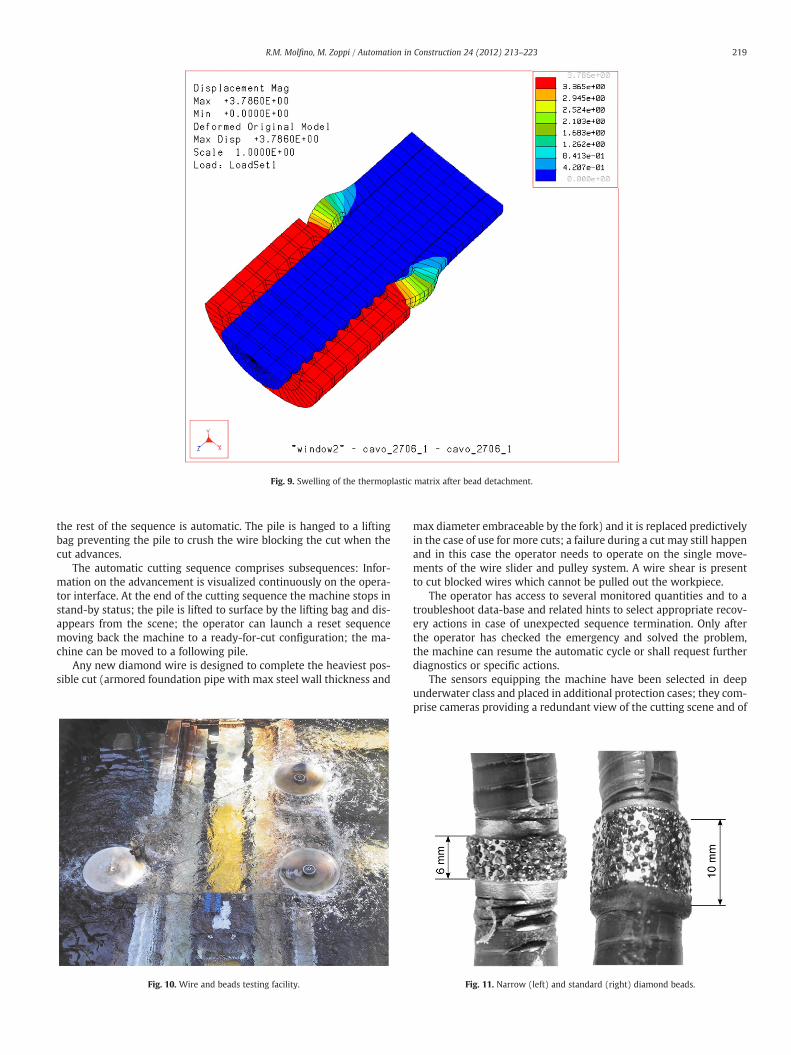
Fig. 9. Swelling of the thermoplastic matrix after bead detachment.
219R.M. Molfino, M. Zoppi / Automation in Construction 24 (2012) 213–223
the rest of the sequence is automatic. The pile is hanged to a liftingbag preventing the pile to crush the wire blocking the cut when thecut advances.
The automatic cutting sequence comprises subsequences: Infor-mation on the advancement is visualized continuously on the opera-tor interface. At the end of the cutting sequence the machine stops instand-by status; the pile is lifted to surface by the lifting bag and dis-appears from the scene; the operator can launch a reset sequencemoving back the machine to a ready-for-cut configuration; the ma-chine can be moved to a following pile.
Any new diamond wire is designed to complete the heaviest pos-sible cut (armored foundation pipe with max steel wall thickness and
Fig. 10. Wire and beads testing facility.
max diameter embraceable by the fork) and it is replaced predictivelyin the case of use for more cuts; a failure during a cut may still happenand in this case the operator needs to operate on the single move-ments of the wire slider and pulley system. A wire shear is presentto cut blocked wires which cannot be pulled out the workpiece.
The operator has access to several monitored quantities and to atroubleshoot data-base and related hints to select appropriate recov-ery actions in case of unexpected sequence termination. Only afterthe operator has checked the emergency and solved the problem,the machine can resume the automatic cycle or shall request furtherdiagnostics or specific actions.
The sensors equipping the machine have been selected in deepunderwater class and placed in additional protection cases; they com-prise cameras providing a redundant view of the cutting scene and of
Fig. 11. Narrow (left) and standard (right) diamond beads.

Fig. 12. Comparison between performances of standard (a) and narrow bead wires (b).
220 R.M. Molfino, M. Zoppi / Automation in Construction 24 (2012) 213–223
the sides and back of the machine, position sensors on all driven axeswith redundancy for the critical motions (slider translation and wirespeed measured at the two pulleys immediately preceding and fol-lowing the wire branch performing the cut), water speed at the ex-tremities of the fork and frame to detect and monitor underwaterstreams affecting stability and motion of the machine, pressure sen-sors at the docking bells to check the anchorage to the seabed duringcutting. The wires of the sensors are routed into steel pipes welded tothe frame of the machine for protection against any accidental im-pact; all pipes reach a common electrical enclosure. The pipes andall enclosures form a closed, sealed circuit filled with oil to preventsea water to get in; the pressure of the circuit is adapted to thewater pressure by a compensation accumulator oil/water with
Fig. 13. Anomalies in deposition and distribut
metal diaphragm and open at the water side (positioned on the topback of the frame of the machine close to the main electricalenclosure).
Signal processing algorithms have been developed, coded andchecked by simulation to satisfy the stated performance require-ments in noisy environment. Each automatic sequence has beensketched, implemented on the 3D model of the vehicle and simulatedextensively. Tests on the machine have been done first off water andunderwater only when very confident of their reliability in allconditions.
The control system hardware is spread in a surface control unit,including a touch screen computer, a surface-to-underwater interfaceand an analogical/digital control unit. The sub-sea unit is positioned
ion of diamond crystals on bead surface.
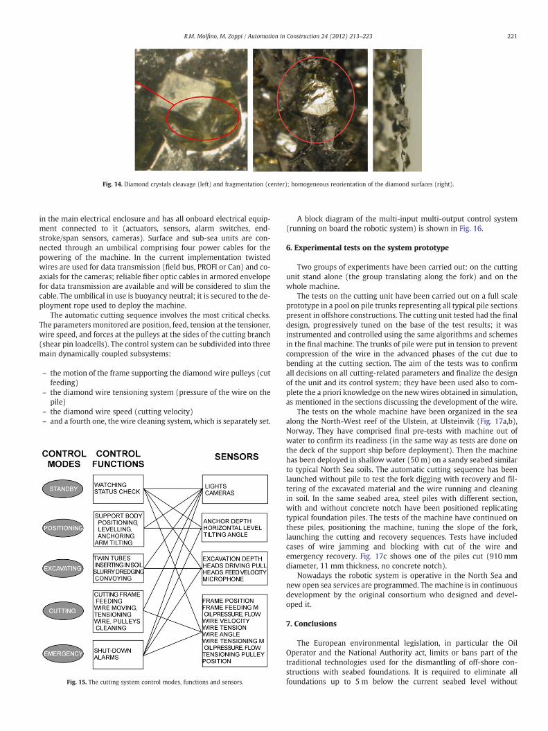
Fig. 14. Diamond crystals cleavage (left) and fragmentation (center); homogeneous reorientation of the diamond surfaces (right).
221R.M. Molfino, M. Zoppi / Automation in Construction 24 (2012) 213–223
in the main electrical enclosure and has all onboard electrical equip-ment connected to it (actuators, sensors, alarm switches, end-stroke/span sensors, cameras). Surface and sub-sea units are con-nected through an umbilical comprising four power cables for thepowering of the machine. In the current implementation twistedwires are used for data transmission (field bus, PROFI or Can) and co-axials for the cameras; reliable fiber optic cables in armored envelopefor data transmission are available and will be considered to slim thecable. The umbilical in use is buoyancy neutral; it is secured to the de-ployment rope used to deploy the machine.
The automatic cutting sequence involves the most critical checks.The parameters monitored are position, feed, tension at the tensioner,wire speed, and forces at the pulleys at the sides of the cutting branch(shear pin loadcells). The control system can be subdivided into threemain dynamically coupled subsystems:
– the motion of the frame supporting the diamond wire pulleys (cutfeeding)
– the diamond wire tensioning system (pressure of the wire on thepile)
– the diamond wire speed (cutting velocity)– and a fourth one, the wire cleaning system, which is separately set.
Fig. 15. The cutting system control modes, functions and sensors.
A block diagram of the multi-input multi-output control system(running on board the robotic system) is shown in Fig. 16.
6. Experimental tests on the system prototype
Two groups of experiments have been carried out: on the cuttingunit stand alone (the group translating along the fork) and on thewhole machine.
The tests on the cutting unit have been carried out on a full scaleprototype in a pool on pile trunks representing all typical pile sectionspresent in offshore constructions. The cutting unit tested had the finaldesign, progressively tuned on the base of the test results; it wasinstrumented and controlled using the same algorithms and schemesin the final machine. The trunks of pile were put in tension to preventcompression of the wire in the advanced phases of the cut due tobending at the cutting section. The aim of the tests was to confirmall decisions on all cutting-related parameters and finalize the designof the unit and its control system; they have been used also to com-plete the a priori knowledge on the newwires obtained in simulation,as mentioned in the sections discussing the development of the wire.
The tests on the whole machine have been organized in the seaalong the North-West reef of the Ulstein, at Ulsteinvik (Fig. 17a,b),Norway. They have comprised final pre-tests with machine out ofwater to confirm its readiness (in the same way as tests are done onthe deck of the support ship before deployment). Then the machinehas been deployed in shallow water (50 m) on a sandy seabed similarto typical North Sea soils. The automatic cutting sequence has beenlaunched without pile to test the fork digging with recovery and fil-tering of the excavated material and the wire running and cleaningin soil. In the same seabed area, steel piles with different section,with and without concrete notch have been positioned replicatingtypical foundation piles. The tests of the machine have continued onthese piles, positioning the machine, tuning the slope of the fork,launching the cutting and recovery sequences. Tests have includedcases of wire jamming and blocking with cut of the wire andemergency recovery. Fig. 17c shows one of the piles cut (910 mmdiameter, 11 mm thickness, no concrete notch).
Nowadays the robotic system is operative in the North Sea andnew open sea services are programmed. The machine is in continuousdevelopment by the original consortium who designed and devel-oped it.
7. Conclusions
The European environmental legislation, in particular the OilOperator and the National Authority act, limits or bans part of thetraditional technologies used for the dismantling of off-shore con-structions with seabed foundations. It is required to eliminate allfoundations up to 5 m below the current seabed level without

Fig. 16. The reactive cutting system control.
222 R.M. Molfino, M. Zoppi / Automation in Construction 24 (2012) 213–223
spreading or moving seabed material which may be highly polluting,avoiding explosives and all means impacting on the marine environ-ment. The robotized machine presented, with its original solution ofdigging fork and diamond wire cutting, is one of the few availabletechnologies today meeting the requirements of the new regulations
Fig. 17. Robot prototype (a) and its deployment wi
with strong benefit the oil and gas extraction industry. In addition,the machine developed contributes to remarkable improvement ofthe working conditions of all personnel involved in the dismantlingoperations, frequently done in areas with adverse or extremeweather.
th view of the control room (b); a cut pile (c).

223R.M. Molfino, M. Zoppi / Automation in Construction 24 (2012) 213–223
Acknowledgment
This research work was co-funded by the European Commissionand ITF consortium. The authors would like to acknowledgeFrancesco Matteucci and Luigi DeMartino of TS-Tecnospamec for thefruitful suggestions, discussions and cooperation.
References
[1] A. Grant, Toxicity and environmental risk assessment of drill cuttings piles,Decommissioning of Offshore Oil and Gas Installations, IBC Global Conferences,London, 2000.
[2] Phillips Norway Group, Search for best cuttings solution, EPOKE, N° 6, 1999.[3] PACT Consortium, “PACT consortium awarded Phillips Petroleum Co UK Ltd
Maureen platform well abandonments” Press Releases, Dec. 3rd 1999.[4] Phillips Petroleum Co, “Maureen refloat programme under way” Press Releases,
August 5th 1999.[5] A. Perry, J.E. Snyder, R.C. Byrd, Amoco Eugene Island 367 Jacket Sectioned, Top-
pled in Place, Offshore, May 1998.[6] E. Cavallo, R.C. Michelini, R.M. Molfino, A remote-operated robotic platform for
underwater decommissioning tasks, 35th Intl. Symposium on Robotics, ISR2004, Paris, March 23–26 2004, pp. 1–6.
[7] E. Cavallo, R.C. Michelini, R.M. Molfino, A robotic system for off-shore plantsdecommissioning, IFAC Conference on Control Applications in Marine Systems— CAMS 2004, Ancona, I, 2004, pp. 89–94.
[8] E. Cavallo, R.C. Michelini, R.M. Molfino, R.P. Razzoli, Robotic equipment for deep-sea operation: digital mock-up and assessment, in: G.L. Kovacs, P. Bertok, G.Haidegger (Eds.), Digital Enterprise, New Challenges, Kluver Acad. Pub., Boston,ISBN: 0-7923-7556-4, 2001, pp. 533–542.
[9] M. Callegari, E. Cavallo, E. Garofalo, R.C. Michelini, R.M. Molfino, R.P. Razzoli, Thedesign of diving robots: set-up assessment by virtual mock-ups, Proc. XI ADMIntl. Conf. on Design Tools and Methods in Industrial Engineering, Palermo, vol.C, Dec. 8–12 1999, pp. 147–154.
[10] M.K.A. Hosseini, O. Omidi, A. Meghdari, G. Vossoughi, A composite rigid bodyalgorithm for modeling and simulation of an underwater vehicle equipped withmanipulator arms, Journal of Offshore Mechanics and Arctic Engineering 128(Issue 2) (May 2006) 119–132.
[11] H.K. Tonshoff, H. Hillmann-Apmann, Diamond tools for wire sawing metal com-ponents, Report, Institute for Production Engineering and Machine Tools, Univer-sity of Hannover, Germany, 2001.
[12] R. Molfino, Underwater robotics latest developments and challenges, UV Europe2007 Shaping the Unmanned Future: Air, Land and Sea Systems, Paris, June14–15 2007, Shephard CD proceedings.
[13] J. Masood, M. Zoppi, R. Molfino, Application of pseudo-elastic wire for hybrid cut-ting robotic tool, in: VDE-Verlag (Ed.), 41th International Symposium on Robot-ics, Munich, Germany, June 7–9 2010.
[14] C.P. Sayers, R.P. Paul, L.L. Whitcomb, D.R. Yoeger, Tele-programming for sub-seatele-operation, using acoustic communication, IEEE J Oceanic Engineering 23(1) (January 1998) 60–71.