A roadmap to robot motion planning software development
10
A Roadmap to Robot Motion Planning Software Development ALEXANDER PE ´ REZ, JAN ROSELL Institute of Industrial and Control Engineering (IOC), Technical University of Catalonia (UPC), Av. Diagonal 647, 11th floor, 08028 Barcelona, Spain Received 2 April 2008; accepted 19 July 2008 ABSTRACT: PhD programs and graduate studies in robotics usually include motion planning among its main subjects. Students that focus their research in this subject find themselves trapped in the necessity of programming an environment where to test and validate their theoretic contributions. The programming of this robot motion planning environment is a big challenge. It requires on the one hand good programming skills involving the use of software development tools, programming paradigms, or the knowledge of computational complexity and efficiency issues. On the other hand it requires coping with different related issues like the modeling of objects, computational geometry problems and graphical representations and interfaces. The mastering of all these techniques is good for the curricula of roboticists with a motion planning profile. Nevertheless, the time and effort devoted to this end must remain reasonable. Within this framework, the aim of this paper is to provide the students with a roadmap to help them in the development of the software tools needed to test and validate their robot motion planners. The proposals are made within the scope of multi-platform open source code. ß 2009 Wiley Periodicals, Inc. Comput Appl Eng Educ 18: 651660, 2010; View this article online at wileyonlinelibrary.com; DOI 10.1002/cae.20269 Keywords: robotics; software development; path planning PROBLEM STATEMENT One of the main tasks in robotics is to plan collision-free paths for a robot from a start to a goal configuration among the obstacles in the workspace. This problem is known as robot motion planning [13]. The basic approach is a computationally hard geometric problem that can get much harder if other issues are to be taken into account like sensor uncertainties, differential constraints, or the existence of dynamic obstacles. Robot motion planners must cope with the modeling of objects and their location, with collision detection and other computational geometry problems, with graph representations and search algorithms, and with graphic rendering and other graphical user interface issues. Therefore, the development of a robot motion planner is not an easy task since it involves many different issues ranging from the use of software development tools to the knowledge of computa- tional geometry solutions. There are some open source motion planners available on the web like An Object-Oriented Programming System for Motion Planning [4] (OOPSMP, www.kavrakilab.org/software), the Motion Planning Kit (http://ai.stanford.edu/mitul/mpk) or the Motion Strategy Library (http://msl.cs.uiuc.edu/msl/). The OOPSMP is a path planner that currently allows solving problems for free-flying robots moving on a plane using the basic versions of either probabilistic roadmaps (PRM, [5]), or rapidly exploring random trees (RRT , [6]). It has the interesting didactic feature of allowing to consecutively execute all the steps of the planning process and showing, for instance, the robot at each of the sampled configurations. Although it is conceived to be flexible and modular (it is implemented using the generic programming paradigm based on XML descriptions), there is not enough documentation yet to allow its use for programming and testing new algorithms or variants. The MSL and the MPK are, on the other hand, basically conceived as tools to prove and illustrate the motion planners developed by their authors, namely the basic RRTs and all its variants (MSL) and the SBL algorithm, a fast single-query probabilistic roadmap path planner (MPK). They also allow dealing with more complex problems involving robot manipulators (MPK also includes a multirobot module), or mobile robots with kinematic constraints (for the case of MSL). Although all these planners have interesting features, they do not cover the needs from a teaching perspective: They are not easy to use and it is hard to get an insight into their structure in order to adapt and extend them to the particular needs. This is the reason why, in order to have an environment where to test and Correspondence to J. Rosell ([email protected]). Contract grant sponsor: CICYT; Contract grant numbers: DPI2007-63665, DPI2008-02448. ß 2009 Wiley Periodicals Inc. 651
-
Upload
alexander-perez -
Category
Documents
-
view
215 -
download
3
Transcript of A roadmap to robot motion planning software development

A Roadmap to RobotMotion Planning SoftwareDevelopmentALEXANDER PEREZ, JAN ROSELL
Institute of Industrial and Control Engineering (IOC), Technical University of Catalonia (UPC), Av. Diagonal 647,
11th floor, 08028 Barcelona, Spain
Received 2 April 2008; accepted 19 July 2008
ABSTRACT: PhD programs and graduate studies in robotics usually include motion planning among its main
subjects. Students that focus their research in this subject find themselves trapped in the necessity of
programming an environment where to test and validate their theoretic contributions. The programming of this
robot motion planning environment is a big challenge. It requires on the one hand good programming skills
involving the use of software development tools, programming paradigms, or the knowledge of computational
complexity and efficiency issues. On the other hand it requires coping with different related issues like the
modeling of objects, computational geometry problems and graphical representations and interfaces. The
mastering of all these techniques is good for the curricula of roboticists with a motion planning profile.
Nevertheless, the time and effort devoted to this end must remain reasonable. Within this framework, the aim of
this paper is to provide the students with a roadmap to help them in the development of the software tools needed
to test and validate their robot motion planners. The proposals are made within the scope of multi-platform open
source code. � 2009 Wiley Periodicals, Inc. Comput Appl Eng Educ 18: 651�660, 2010; View this article online at
wileyonlinelibrary.com; DOI 10.1002/cae.20269
Keywords: robotics; software development; path planning
PROBLEM STATEMENT
One of the main tasks in robotics is to plan collision-free paths for
a robot from a start to a goal configuration among the obstacles in
the workspace. This problem is known as robot motion planning
[1�3]. The basic approach is a computationally hard geometric
problem that can get much harder if other issues are to be taken
into account like sensor uncertainties, differential constraints, or
the existence of dynamic obstacles. Robot motion planners must
cope with the modeling of objects and their location, with
collision detection and other computational geometry problems,
with graph representations and search algorithms, and with
graphic rendering and other graphical user interface issues.
Therefore, the development of a robot motion planner is not an
easy task since it involves many different issues ranging from the
use of software development tools to the knowledge of computa-
tional geometry solutions.
There are some open source motion planners available on
the web like An Object-Oriented Programming System for Motion
Planning [4] (OOPSMP, www.kavrakilab.org/software), the
Motion Planning Kit (http://ai.stanford.edu/mitul/mpk) or the
Motion Strategy Library (http://msl.cs.uiuc.edu/msl/). The
OOPSMP is a path planner that currently allows solving problems
for free-flying robots moving on a plane using the basic versions
of either probabilistic roadmaps (PRM, [5]), or rapidly exploring
random trees (RRT, [6]). It has the interesting didactic feature of
allowing to consecutively execute all the steps of the planning
process and showing, for instance, the robot at each of the
sampled configurations. Although it is conceived to be flexible
and modular (it is implemented using the generic programming
paradigm based on XML descriptions), there is not enough
documentation yet to allow its use for programming and testing
new algorithms or variants. The MSL and the MPK are, on the
other hand, basically conceived as tools to prove and illustrate the
motion planners developed by their authors, namely the basic
RRTs and all its variants (MSL) and the SBL algorithm, a fast
single-query probabilistic roadmap path planner (MPK). They
also allow dealing with more complex problems involving robot
manipulators (MPK also includes a multirobot module), or
mobile robots with kinematic constraints (for the case of MSL).
Although all these planners have interesting features, they
do not cover the needs from a teaching perspective: They are not
easy to use and it is hard to get an insight into their structure in
order to adapt and extend them to the particular needs. This is the
reason why, in order to have an environment where to test and
Correspondence to J. Rosell ([email protected]).Contract grant sponsor: CICYT; Contract grant numbers:
DPI2007-63665, DPI2008-02448.
� 2009 Wiley Periodicals Inc.
651

validate theoretic contributions in motion planning, it ends up
being more efficient to build a planner from scratch. From the
learning point of view, in the scope of PhD programs and graduate
studies in robotics, this is not a bad issue, since it gives the
students the opportunity to face different problems and to acquire
a global view. Nevertheless, some guidelines are always welcome
in order to keep the effort reasonably bounded. This paper makes
a proposal of some useful tools (and illustrates how to use them)
with the aim of paving the path towards the development of
motion planning software.
The paper is structured as follows. Tools Section presents
the set of tools with which the students must get involved in the
development of robot motion planning software. They are
building bricks that cover from general software development
tools, operating systems and compliers to graphics, GUIs and
computational geometry libraries. Certainly many different
alternatives do exist for each of them. The proposal of this paper
is made having in mind an open source philosophy and a multi-
platform approach, and is currently being used with success at the
Technical University of Catalonia to teach ‘‘Planning in robotics’’
within the PhD Program ‘‘Automatic Control, Robotics and
Computer Vision (ARV)’’. After the tools’ overview, Kick-Off
Examples Section presents some kick-off examples to facilitate
the students’ start-up. The examples code can be downloaded
from http://iocnet.upc.edu/usuaris/JanRosell//EducationalTools.
html.
TOOLS
Software Development Tools
When a new software project begins, it is necessary to define the
tools to be used all along the process. Which programming
techniques will be used? How will a design be described? How
will the development history and backups of the project be
maintained? A motion planning software is not a small
application; it really is a big software project where many
libraries are working together. For this reason, it is important to
begin with a good task plan covering all the development steps.
One of the most published programming paradigms in the
last decade is the Object Oriented Programming (OOP, [7]).
Through the OOP it is possible to comfortably work with the
models (objects) of all the actors involved in the problem, like the
configuration space, the workspace, the obstacles and the robots
for the case of motion planning problems. OOP may be seen as a
collection of cooperating objects, as opposed to a traditional view
in which a program may be seen as a group of procedures. Every
type of object in a OOP application is defined by a class. In OOP,
each object is capable of receiving messages, processing data, and
sending messages to other objects. OOP allows the creation of
modular and reusable code.
Closer to the OOP methodology, grows the Unified
Modeling Language that is a meta language used to graphically
show a software design [8]. Documentation about this meta
language is regularly posted in the Object Group website
(www.uml.org). Using an UML graphic tool like StarUML
(www. staruml.com) it is possible to make an initial global design
at class level, that can later be refined or modified (Fig. 1). One
advantage of using the StarUML over other tools is its ability to
generate the source and header files (*.cpp and *.h files,
respectively) for all the associated classes in the design.
Furthermore it can, in a process called reverse engineering,
extract a graph of the class hierarchy from all the project files.
All the steps in a long software developing process must be
stored for tracking and debugging purposes. A good way of doing
this is through a control version system like Subversion SVN
(https://subversion.tigris.org). These systems provide a good
environment to store and restore any possible version of each file
in the project all along the development time, and it is very useful
Figure 1 The UML model of a motion planner project where the main classes (highlighted in green) represent the
workspace, the configuration space, the configurations and the geometric elements (implemented in the derived classes
representing obstacles and the robot, highlighted in red). [Color figure can be viewed in the online issue, which is
available at wileyonlinelibrary.com.]
652 PEREZ AND ROSELL

to manage projects involving several programmers at the
same time. Other tools like CVS (www.nongnu.org/cvs) or
a commercial solution like SafeSource (http://msdn. microsoft.
com/en-us/vs2005/aa718670.aspx), can be used, but SVN is
currently the preferred control version system in the open
source community. It provides a set of tools for common
administrative server tasks and client operations. For a complete
reference on SVN, see Ref. [9].
An effective and easy solution of the server side is OpenSVN
(https://opensvn.csie.org), it is an open-source initiative for open-
source projects. It provides a good access and availability and it
can store a large amount of files. For the client side, TortoiseSVN
(http://tortoisesvn.net) is a Windows shell extension which
integrates into Windows Explorer. For Linux environments,
kdesvn (http://kdesvn.alwins-world.de) is a high integrated
application for KDesktop. Similar tools can be found for other
Linux desktops.
These tools can be complemented by many others like those
that allow the comparing of two versions of the same file to track
and revise the changes (e.g., winmerge at www.winmerge.org,
KDiff3 at http://kdiff3.sourceforge.net or Meld at http://meld.-
source forge.net).
Finally, a good programmer should properly document the
code. This can easily be done using Doxygen (www.doxyge-
n.org), a multi-platform documentation system for several
languages like Cþþ and java. By only adding some comments
within the code with a special mark, this software automatically
generates a great documentation.
O.S. and Compilers
Usually, the main programming language used for this kind of
applications is Cþþ. It is desirable that the software be multi-
platform, in other words that it can either run in Windows or
Linux. To achieve this purpose, it is necessary to use for each
platform its own compiler: the cl compiler can be used on
Windows and gcc (http://gcc.gnu.org) on Linux. The cl compiler
can be obtained from them Microsoft web site when installing any
license type of Visual Studio, including the free license Express
Edition (www.microsoft.com/express/download). Several other
Cþþ compilers can be found on Internet from many other
sources like HP, Borland or Intel and they can be used in Windows
and/or Linux, although the use of system compliers is preferred.
The gcc and cl compilers are command line, and the process
to build the applications can be a bit thorny. For this reason, it is
useful to use another program to manage the compilation and
linkage processes. This application in ‘‘nix’’ environments is
called Make; in Windows the analogous application is called
nmake. These two applications do not describe the process in the
same way. The solution to this problem is CMake (www.cma-
ke.org), an open-source multi-platform make system. CMake has
a GUI wizard in Windows (Fig. 2) that helps to configure the
process. A complete reference for CMake is available in Ref.
[10]. The CMake utility allows the user to prepare the project in
both Windows and Linux, relieving him/her from the task of
configuring the project for each platform. This helps the
applications to be really multi-platform since the projects for
compiling and linking them are easily obtained for each platform
from the instructions coded using a script language in a text file
called CmakeList.txt.
Each programmer has its own preferences for the Integrated
Developer Environment to be used to write and debug the code in
a friendly way. IDEs like Visual Studio on Windows or KDevelop
on Linux offer many facilities to speed up the programming
process (Fig. 3), but each one has its own particularities in the
project description and management. In Windows, CMake can
configure the project file for a particular version of Visual Studio
or create a descriptive file to be processed with nmake. In Linux,
CMake can create a descriptive file called Makefile and in a future
version it will configure the project for KDevelop.
Graphic Tools
Graphics. The graphic interface to show three-dimensional
models can be build using Coin3D (www.coin3d.org). This
graphics library is based on OpenInventor sources delivered from
Silicon Graphics and it is currently the implementation adopted
for all Debian Linux distributions. Coin3D provides an interface
Figure 2 CMake GUI in Windows. [Color figure can be viewed in the online issue, which is available at
wileyonlinelibrary.com.]
ROBOT MOTION PLANNING SOFTWARE DEVELOPMENT 653

similar to a CAD software. It can manage either basic models like
spheres, cones and cubes, or general forms modeled with
triangular meshes (Fig. 4). Furthermore it is multi-platform and
therefore it can also compile and run on Windows. It can be
installed from a binary distributions repository or compiled from
the source code. Coin3D must work together with a GUI library,
that can be either Qt, Motif/Xt, Windows or MacOs APIs. For this
interaction, SoQt or Quater, SoXt, SoWin, and Sc21 libraries are,
respectively, required.
Any three-dimensional model can be described as a text file
through Inventor or VRML languages (http://www.w3.org/
MarkUp/VRML). They describe a scene graph with high level
objects like cubes, cylinders, cones or spheres or any grouping of
these, as well as triangular meshes. Also, property nodes are
introduced to affect the way shapes are drawn. Coin3D can load
any scene described with either Inventor or VRML files.
Several other tools could be used to make the graphical
representation of three-dimensional worlds, like VTK (www.vtk.
org) or the sgi OpenInventor release (oss.sgi.com/projects/
inventor); but Coin3D has been used in many commercial as
well as open-source projects and it has an active and efficient
support list.
GUIs. Usually, any software application has a GUI to
interchange information with the user. Several libraries can be
used to build GUIs, some of them being platform specific like
Figure 3 Integrated Developer Environment in Linux and Windows and their powerful helps. [Color figure can be
viewed in the online issue, which is available at wileyonlinelibrary.com.]
Figure 4 Three-dimensional models described using Coin3D. This figure shows the difference between primitive
solids (cubes and cylinders) and triangular meshes. [Color figure can be viewed in the online issue, which is available at
wileyonlinelibrary.com.]
654 PEREZ AND ROSELL

MFC in Windows. Nevertheless, if a multi-platform application is
desired, it is necessary to use the same library in all OS. In this
direction, several graphical windows systems initially born in
Linux environments have migrated to Windows or Mac OS’s, like
GTKþ (www.gtk.org), wxWidgets (www.wxwidgets.org), FOX
(http://www.fox-toolkit.com) or the Qt library (http://trolltech.
com/products/qt).
The Qt library is currently used in a great variety of open-
source projects and commercial applications and it has more than
10 years of developing experience and it can easily be integrated
with Coin3D. Moreover, Qt has a friendly GUI designer tool
(QtDesigner) based on drag and drop that helps in this creative
process (Fig. 5).
To build a GUI with a Coin3D scene a SoQt library is
required. This library must be properly compiled for a specific Qt
and Coin3D version.
The Qt library is not only a graphic objects set, but a
complete library that cover many topics of the software develop-
ing process, for example, it provides components for XML
processing, string manipulation, file reading and much more.
Qt has one particularity that makes it different from others
GUI frameworks: the signal and slots technology used for the
communication between objects. It is a safer alternative to the use
of the callback functions technique. The objects do not need
knowledge about each other to communicate; the signals and the
slots allow for a loosely coupled programming. In the build
process, this characteristic entails an extra process for any object
that uses it. Qt calls this role Meta-Object System and the library
provides the tool called moc for processing any object that use it.
See Blanchette and Summerfield [11] and online documentation.
Practical Setup. To obtain a GUI with all the common
functionalities like toolbars, menus, frames, tabs an so on,
together with a three dimensional space, a correct interaction
between the Coin3D and Qt libraries is needed using the small
‘‘glue’’ library SoQt. This library provides all the necessary
elements to show a Coin3D window inside any Qt container like
panels or frames.
These three libraries (Coin3D, Qt, and SoQt) must be
compiled in the same compiler, for example, gcc or cl. In order to
properly configure the developing environment these steps must
be followed:
(a) Create the system variables $(QTDIR) and $(COIN3D).
(b) Download the Coin3D library and decompress it in the
$(COIN3D) folder.
(c) Go to the build folder in Windows or the src folder in
Linux and build all the libraries included.
(d) Install the latest build libraries and header files associated
to the $(COIN3D) folder through ‘‘make install’’ in Linux
or through bat files in Windows.
(e) Download the Qt4 open source library and decompress in
$(QTDIR) folder. If the operating system is Windows you
need to patch it to be used with the cl compiler (See
additional information in http://psi-im.org/wiki/Compi-
ling_Qt4_on_Windows).
(f) Configure Qt4 library using the qconfigure utility in Linux
or using qconfigure.bat in Windows.
(g) Build the library using make in Linux or nmake in
Windows.
(h) Download SoQt and decompress it in a folder.
(i) Go to the build folder in Windows or the src folder in Linux
and build all the libraries included.
(j) Install the latest build libraries and header files associated
to the $(QTDIR) folder through ‘‘make install’’ in Linux or
through bat files in Windows.
Now the framework has the capabilities to compile and
show a three-dimensional window inside any QWidget container
like the QTabWidget shown in Figure 6, through invoking the
SoQtExaminerViewer constructor. A data structure Viewer is
shown in the same figure and it groups several Coin3D data types.
Figure 5 QtDesigner snapshot. This facility provides every common component used in a GUI. [Color
figure can be viewed in the online issue, which is available at wileyonlinelibrary.com.]
ROBOT MOTION PLANNING SOFTWARE DEVELOPMENT 655

Computational Geometry Tools
Collision Detection. An important part of a motion planner is the
collision check process that verifies if configurations are free or
not. Several open-source libraries are available on the internet.
They use different techniques, like Oriented Bounding Box [12],
Axis-Aligned Bounding Box [13], or Swept Spheres Volumes
[14], each one with its own advantages and disadvantages. A good
alternative is the Proximity Query Package (www.cs.unc.edu/
geom/SSV) in forward PQP. There are many applications using it
since it is based on quick and reliable algorithms to find collisions
between objects described by triangular meshes, and also it can be
asked for the separation distances between models.
For rendering purposes PQP must be connected to a
graphics library like Coin3D, since PQP does not have any
graphics components. PQP models are based on triangular
meshes. These triangular meshes can be obtained from VRML or
Inventor models using a conversion procedure provided by the
Coin3D library (Fig. 7).
Motion Planning Tools. Currently, sampling-based methods are
the most commonly used methods in motion planning problems.
These methods consist in the generation of collision-free samples
of configuration space (Cspace) and in their inter-connection with
free paths, forming either roadmaps (PRM [5]) or trees (RRT [6]).
PRM planners are conceived as multi-query planners, while RRT
planners are developed to rapidly solve a single-query problem.
Some of the needs to develop a sampling-based motion planner
are: (a) the generation of samples, (b) the search of nearest
neighbors, (c) graph representations and search algorithms.
Samples can be generated using either a random or a
deterministic sequence. Random samples are generated by
randomly setting the values of the configuration coordinates.
These values are usually obtained using a pseudo-random number
generator with long period and good statistical acceptance, like
the one provided by Rabin [15] that gives better results than the
rand function of the standard C library. Deterministic sequences
provide samples giving a good incremental and uniform coverage
of Cspace. The Halton sequence is one of the best low-
discrepancy sequences (http://people.scs.fsu.edu/burkardt, [16]).
Some of these sequences can also provide a lattice structure to
easily allow the determination of the neighborhood relations, like
the Sdk sequence [17] that is based on a multi-grid cell
decomposition with an efficient cell coding, and on the use of
the digital construction method.
In order to connect samples to capture the connectivity of
the free configuration space, it is necessary to find, for each
sample, which are its nearest neighbors. This can be efficiently
solved using the ANN library (www.cs.umd.edu/mount/ANN,
[18]). ANN is a library written in Cþþ, which supports data
structures and algorithms for both exact and approximate nearest
neighbor searching in arbitrarily high dimensions. A set P of
input samples are preprocessed into a kd-tree data structure so
that given any query sample q, the nearest or generally k-nearest
samples of P to q can be reported efficiently. The distance
between two samples can be defined in many ways. ANN assumes
that distances are measured using any class of distance functions
called Minkowski metrics. These include the well known
Euclidean distance, Manhattan distance, and max distance. An
adaptation of the ANN library to different topologies of Cspaces,
with its corresponding metrics is available at msl.cs.uiuc.edu/
yershova, [19].
To deal with graph data structures, the Boost Graph Library
(www.boost.org/libs/graph, [20]) is a library implemented using
the generic programming paradigm that provides a standardized
generic interface with template search algorithms like Breadth
First, Depth First, or Uniform Cost, and other algorithms that
Figure 6 Adding a 3D viewer into a tab control in Qt4. The most
important instructions are showed in dark and they are used to create the
viewer, to push it into the tab container and bring it to the front.Figure 7 PQP model graphically represented as a Coin3D triangular
mesh. The PQP model has been obtained from several Coin3D primitives
(cubes and cylinders). [Color figure can be viewed in the online issue,
which is available at wileyonlinelibrary.com.]
656 PEREZ AND ROSELL

allows access to a graph’s structure. These algorithms can easily
be tailored to any particular application. The Boost Graph Library
is a header-only library and does not need to be built to be used.
Practical Setup
Loading Scenes. Scenes can be defined using description files in
text, XML, VRML, or Inventor code. Coin3D uses either Inventor
or VRML as input files (these models of robots and obstacles can
be obtained from the Internet or converted from CAD models). To
help the user in defining a scene, however, the XML language can
be very useful. A good alternative to easy handle XML files is to
use the Simple API for XML (SAX, http://sax.sourceforge.net).
The SAX technique defines a way to write and read every tag and
their parameters in an XML file to be processed. The other main
technique to handle these files is the Document Type Definition
(DTD, http://www.w3schools.com/dtd), but this is a more
complex technique.
The XML files can contain information of the robot and of
the obstacles (VRML or Inventor files, names, positions, and
scales), and any other aspect related to the definition of a planning
problem, like the initial and goal configurations. As an example,
Figure 8 shows an XML file that with the following information:
the problem’s type is R6 (meaning that the Cspace is that of a
kinematic chain with six links), the workspace represented in the
Inventor file columns.iv with a scale factor of 1.8, the robot
described in the Inventor file rtx90.iv with a scale factor of 0.7,
and the start and goal joint values. Any extra parameter needed
can be easily added by defining the corresponding tags.
Qt has an XML module based on the SAX technique. It has an
abstract class named QXmlDefaultHandler that can be quickly
tailored to any file structure. Only two main functions need to be
implemented, called startElement and endElement, to process
each defined element in the input XML file.
Connecting PQP With Coin3D. PQP performs collision
checking using its own models, based on triangular meshes,
that are usually build from the corresponding Inventor ones. In
order to efficiently use these models, a higher level class can be
first defined to represent the model of any 3D object. This class is
composed by an Inventor model used for visualization purpose,
and a PQP model used for computational geometry purposes
(collision or distance check). Also, the class must have
procedures to convert from one model to the other. As an
example, Figure 9 shows the conversion function between models
of a class of this type, called Element. This function makes a PQP
model from an Inventor model.
The function shown in Figure 9 uses several tools offered by
Coin3D in order to extract points from any basic primitive (e.g.,
cylinders, cubes,. . .) or from any three-dimensional object, and
group them in triangles. This set of triangles conform the PQP
model. Since collision queries need to be answered as quick as
possible, the best alternative is to make this conversion of models
only once and then, for each query required, explicitly pass the
position and orientation of the robot as a parameter of the query
function. Care must be taken with Coin3D�PQP spatial trans-
formations, because PQP and Coin3D use a different mathemat-
ical representation for the transformation matrix and this can
give many troubles if not correctly handled (see the online
documentation in www. coin3d.org).
KICK-OFF EXAMPLES
This section first presents some useful tips to prepare a project
using CMake and then proposes three examples. The code can be
downloaded from http://iocnet.upc.edu//usuaris/JanRosell/Edu-
cationalTools.html; it includes a Readme file with instructions to
generate the executable files. These examples illustrate how to
load a scene and show it using Coin3D, how to convert from
Coin3D models to PQP models and test for collisions, and finally
how to sample a configuration space. All these are basic needs in
the development of a planner. The complete documentation of the
classes used in these examples can be obtained from the code
using the Doxygen documentation system.
Preparing a Project
The CMake utility allows the user to prepare the project in both
Windows and Linux, relieving him from the task of configuring
the project for each platform. This helps the applications to be
really multi-platform since the projects for compiling and linking
them are easily obtained for each platform from the instructions
coded in a text file (CMakeList.txt) using a simple script
language. An example of a CMakeList file that generates an
executable is the following:
The first two lines indicates where to find all *.cpp and *.h
files that have to be included in the project. The third line makesFigure 8 XML file describing a scene.
Figure 9 A possible implementation of a method to obtain the PQP
model from the Inventor one. Shown in dark the main Coin3D functions
used to extract the triangular mesh from the primitive solids.
ROBOT MOTION PLANNING SOFTWARE DEVELOPMENT 657

the executable and the last five lines link it with Coin3D, SoQt,
and Qt libraries. This linking process depends on the OS and the
CMake provides the convenient tools to choose the correct
modifiers in each situation.
CMake has many modules to search and configure specific
libraries like Qt4, to avoid possible errors during the config-
uration process:
These modules assume some defaults setup values in the
configuration of these libraries that have to be kept in mind to
avoid passing the wrong values to the compiler or linker (if
different values from the default ones are desired they have to be
explicitly set). For instance, if the use of the XML processing
module from Qt4 is required, you should add the following two
lines in the CMakeLists file because otherwise it is turned off by
default:
When these modules are not found, like with the Coin3D
library, all the required values must be explicitly set for the
compiler and the linker, although with some experience it is
possible to program a module to search and configure any library.
One feature of Coin3D is the use of signals and slots
technique. This particularity causes an extra processing for any
objects that use it, that CMake handles with the following lines:
The first line preprocesses the Graphical User Interface
created with the QtDesigner, for example, file myinterface.ui, and
creates a header file called ui_myinterface.h referenced with the
variable QTUI_H_SRC. The second line deals with the extra step,
called moc or Meta-Object Compilation, that generates, using the
file gui.h where the slots are defined, the source file moc_gui.cxx
referenced by the variable QT_MOC_SRC. At the third line, both
QTUI_H_SRC and QT_MOC_SRC are added to the source files
used to create the executable.
Another useful tip for the Windows environment is the
following. When a GUI application based on Qt is running on
Windows, a command window always appears. If this is not
desired (no output to the standard output is required), the Qt4
module called QtMain should be used instead of the API winmain
function. In order to correctly generate a WIN32 executable, be
careful to add the following lines to the CMakeList file.
The CMakeLists.txt files of the following examples can serve
as a first approach to the subject. More information about how to
configure, run and use the CMake application can be read from the
book Mastering CMake [10] or directly from the application help.
Loading a Scene
Loading a scene and defining the problem is the first need to be
faced. The robot, the obstacles and the limits of the workspace are
to be introduced to properly show the problem scene. This
information can be given in an XML file. This example uses a
class named StrucParse to extract and process this information.
For the modeling, a class named Element is defined as the
abstraction of any tree-dimensional object to be introduced in the
scene. The geometry of the objects is given in either Inventor or
VRML files. Figure 10 shows the snapshot of the scene loaded,
where an L-shaped free-flying object is located among two
obstacle columns.
Testing PQP
This example shows how to create the PQP models from Coin3D
models and how to make collision queries. It also serves as
example to the generation of a GUI that includes sliders, buttons,
tabs and 3D scenes. To execute this example it is necessary to first
obtain and compile the PQP library properly. Figure 11 shows a
snapshot of the GUI; it contains two tabs with Coin3D scenes, the
first one with the original Inventor scene, the other one showing
the PQP model where the triangular mesh is highlighted.
Figure 10 GUI of loading scene example. [Color figure can be viewed
in the online issue, which is available at wileyonlinelibrary.com.]
Figure 11 GUI of Testing PQP example. [Color figure can be viewed in
the online issue, which is available at wileyonlinelibrary.com.]
658 PEREZ AND ROSELL
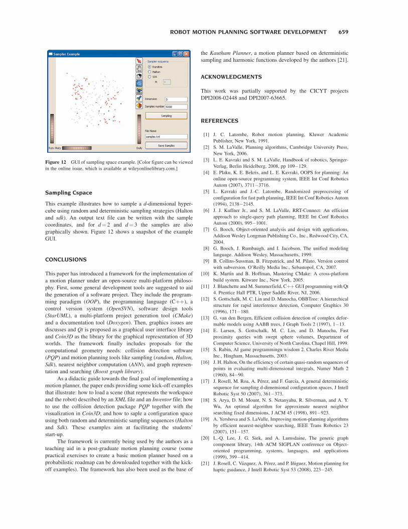
Sampling Cspace
This example illustrates how to sample a d-dimensional hyper-
cube using random and deterministic sampling strategies (Halton
and sdk). An output text file can be written with the sample
coordinates, and for d¼ 2 and d¼ 3 the samples are also
graphically shown. Figure 12 shows a snapshot of the example
GUI.
CONCLUSIONS
This paper has introduced a framework for the implementation of
a motion planner under an open-source multi-platform philoso-
phy. First, some general development tools are suggested to aid
the generation of a software project. They include the program-
ming paradigm (OOP), the programming language (Cþþ), a
control version system (OpenSVN), software design tools
(StarUML), a multi-platform project generation tool (CMake)
and a documentation tool (Doxygen). Then, graphics issues are
discusses and Qt is proposed as a graphical user interface library
and Coin3D as the library for the graphical representation of 3D
worlds. The framework finally includes proposals for the
computational geometry needs: collision detection software
(PQP) and motion planning tools like sampling (random, Halton,
Sdk), nearest neighbor computation (ANN), and graph represen-
tation and searching (Boost graph library).
As a didactic guide towards the final goal of implementing a
motion planner, the paper ends providing some kick-off examples
that illustrate: how to load a scene (that represents the workspace
and the robot) described by an XML file and an Inventor file; how
to use the collision detection package PQP together with the
visualization in Coin3D; and how to saple a configuration space
using both random and deterministic sampling sequences (Halton
and Sdk). These examples aim at facilitating the students’
start-up.
The framework is currently being used by the authors as a
teaching aid in a post-graduate motion planning course (some
practical exercises to create a basic motion planner based on a
probabilistic roadmap can be downloaded together with the kick-
off examples). The framework has also been used as the base of
the Kautham Planner, a motion planner based on deterministic
sampling and harmonic functions developed by the authors [21].
ACKNOWLEDGMENTS
This work was partially supported by the CICYT projects
DPI2008-02448 and DPI2007-63665.
REFERENCES
[1] J. C. Latombe, Robot motion planning, Kluwer Academic
Publisher, New York, 1991.
[2] S. M. LaValle, Planning algorithms, Cambridge University Press,
New York, 2006.
[3] L. E. Kavraki and S. M. LaValle, Handbook of robotics, Springer-
Verlag, Berlin Heidelberg, 2008, pp 109�129.
[4] E. Plaku, K. E. Bekris, and L. E. Kavraki, OOPS for planning: An
online open-source programming system, IEEE Int Conf Robotics
Autom (2007), 3711�3716.
[5] L. Kavraki and J.-C. Latombe, Randomized preprocessing of
configuration for fast path planning, IEEE Int Conf Robotics Autom
(1994), 2138�2145.
[6] J. J. Kuffner Jr., and S. M. LaValle, RRT-Connect: An efficient
approach to single-query path planning, IEEE Int Conf Robotics
Autom (2000), 995�1001.
[7] G. Booch, Object-oriented analysis and design with applications,
Addison Wesley Longman Publishing Co., Inc., Redwood City, CA,
2004.
[8] G. Booch, J. Rumbaugh, and I. Jacobson, The unified modeling
language. Addison Wesley, Massachusetts, 1999.
[9] B. Collins-Sussman, B. Fitzpatrick, and M. Pilato, Version control
with subversion. O’Reilly Media Inc., Sebastopol, CA, 2007.
[10] K. Martin and B. Hoffman, Mastering CMake: A cross-platform
build system. Kitware Inc., New York, 2005.
[11] J. Blanchette and M. Summerfield, CþþGUI programming with Qt
4. Prentice Hall PTR, Upper Saddle River, NJ, 2006.
[12] S. Gottschalk, M. C. Lin and D. Manocha, OBBTree: A hierarchical
structure for rapid interference detection, Computer Graphics 30
(1996), 171�180.
[13] G. van den Bergen, Efficient collision detection of complex defor-
mable models using AABB trees, J Graph Tools 2 (1997), 1�13.
[14] E. Larsen, S. Gottschalk, M. C. Lin, and D. Manocha, Fast
proximity queries with swept sphere volumes, Department of
Computer Science, University of North Carolina, Chapel Hill, 1999.
[15] S. Rabin, AI game programmingn wisdom 2. Charles River Media
Inc., Hingham, Massachusetts, 2003.
[16] J. H. Halton, On the efficiency of certain quasi-random sequences of
points in evaluating multi-dimensional integrals, Numer Math 2
(1960), 84�90.
[17] J. Rosell, M. Roa, A. Perez, and F. Garcıa, A general deterministic
sequence for sampling d-dimensional configuration spaces, J Intell
Robotic Syst 50 (2007), 361�373.
[18] S. Arya, D. M. Mount, N. S. Netanyahu, R. Silverman, and A. Y.
Wu, An optimal algorithm for approximate nearest neighbor
searching fixed dimensions, J ACM 45 (1998), 891�923.
[19] A. Yershova and S. LaValle, Improving motion-planning algorithms
by efficient nearest-neighbor searching, IEEE Trans Robotics 23
(2007), 151�157.
[20] L.-Q. Lee, J. G. Siek, and A. Lumsdaine, The generic graph
component library, 14th ACM SIGPLAN conference on Object-
oriented programming, systems, languages, and applications
(1999), 399�414.
[21] J. Rosell, C. Vazquez, A. Perez, and P. Iniguez, Motion planning for
haptic guidance, J Intell Robotic Syst 53 (2008), 223�245.
Figure 12 GUI of sampling space example. [Color figure can be viewed
in the online issue, which is available at wileyonlinelibrary.com.]
ROBOT MOTION PLANNING SOFTWARE DEVELOPMENT 659
BIOGRAPHIES
Alexander Perez was born in Bogota,
Colombia, in 1975. He is a Mechanical
Engineer from the National University of
Colombia (1999), and MSc in Electronic and
Computer Engineering from Los Andes Uni-
versity (Bogota, Colombia) in 2003. He has
worked as Project Engineer and he was
auxiliary professor at the National University
of Colombia and the University New Granada.
Since 2004 he is Assistant professor in the Electronic Engineering
Faculty of the ‘‘Escuela Colombiana de Ingenierıa ‘‘Julio Garavito’’
placed in Bogota, Colombia. Presently, He is researching in the robot
motion planning area inside of Institute of Industrial and Control
Engineering.
Jan Rosell received the BS degree in Tele-
comunication Engineering and the PhD degree
in Advanced Automation and Robotics from
the Technical University of Catalonia, Barce-
lona, Spain, in 1989 and 1998, respectively. He
joined the Institute of Industrial and Control
Engineering in 1992 where he has developed
research activities in robotics. He has been
involved in teaching activities in Automatic
Control and Robotics as Assistant Professor since 1996 and as
Associate Professor since 2001. His current technical areas include
robot motion planning, haptics, robotic assembly and manufacturing
automation.
660 PEREZ AND ROSELL