A Review of Morphing Aircraft - Michael I Friswellmichael.friswell.com/PDF_Files/J194.pdfA Review of...
55
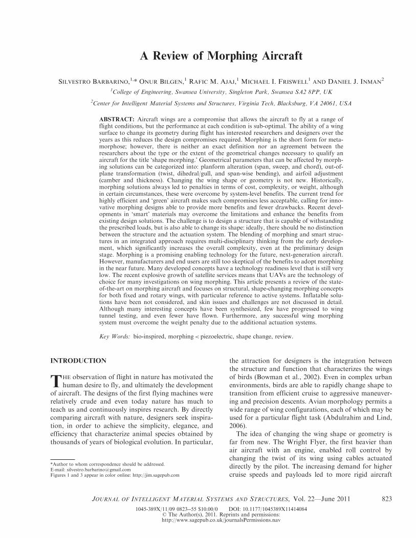
A Review of Morphing Aircraft SILVESTRO BARBARINO, 1, *ONUR BILGEN, 1 RAFIC M. AJAJ, 1 MICHAEL I. FRISWELL 1 AND DANIEL J. INMAN 2 1 College of Engineering, Swansea University, Singleton Park, Swansea SA2 8PP, UK 2 Center for Intelligent Material Systems and Structures, Virginia Tech, Blacksburg, VA 24061, USA ABSTRACT: Aircraft wings are a compromise that allows the aircraft to fly at a range of flight conditions, but the performance at each condition is sub-optimal. The ability of a wing surface to change its geometry during flight has interested researchers and designers over the years as this reduces the design compromises required. Morphing is the short form for meta- morphose; however, there is neither an exact definition nor an agreement between the researchers about the type or the extent of the geometrical changes necessary to qualify an aircraft for the title ‘shape morphing.’ Geometrical parameters that can be affected by morph- ing solutions can be categorized into: planform alteration (span, sweep, and chord), out-of- plane transformation (twist, dihedral/gull, and span-wise bending), and airfoil adjustment (camber and thickness). Changing the wing shape or geometry is not new. Historically, morphing solutions always led to penalties in terms of cost, complexity, or weight, although in certain circumstances, these were overcome by system-level benefits. The current trend for highly efficient and ‘green’ aircraft makes such compromises less acceptable, calling for inno- vative morphing designs able to provide more benefits and fewer drawbacks. Recent devel- opments in ‘smart’ materials may overcome the limitations and enhance the benefits from existing design solutions. The challenge is to design a structure that is capable of withstanding the prescribed loads, but is also able to change its shape: ideally, there should be no distinction between the structure and the actuation system. The blending of morphing and smart struc- tures in an integrated approach requires multi-disciplinary thinking from the early develop- ment, which significantly increases the overall complexity, even at the preliminary design stage. Morphing is a promising enabling technology for the future, next-generation aircraft. However, manufacturers and end users are still too skeptical of the benefits to adopt morphing in the near future. Many developed concepts have a technology readiness level that is still very low. The recent explosive growth of satellite services means that UAVs are the technology of choice for many investigations on wing morphing. This article presents a review of the state- of-the-art on morphing aircraft and focuses on structural, shape-changing morphing concepts for both fixed and rotary wings, with particular reference to active systems. Inflatable solu- tions have been not considered, and skin issues and challenges are not discussed in detail. Although many interesting concepts have been synthesized, few have progressed to wing tunnel testing, and even fewer have flown. Furthermore, any successful wing morphing system must overcome the weight penalty due to the additional actuation systems. Key Words: bio-inspired, morphing < piezoelectric, shape change, review. INTRODUCTION T HE observation of flight in nature has motivated the human desire to fly, and ultimately the development of aircraft. The designs of the first flying machines were relatively crude and even today nature has much to teach us and continuously inspires research. By directly comparing aircraft with nature, designers seek inspira- tion, in order to achieve the simplicity, elegance, and efficiency that characterize animal species obtained by thousands of years of biological evolution. In particular, the attraction for designers is the integration between the structure and function that characterizes the wings of birds (Bowman et al., 2002). Even in complex urban environments, birds are able to rapidly change shape to transition from efficient cruise to aggressive maneuver- ing and precision descents. Avian morphology permits a wide range of wing configurations, each of which may be used for a particular flight task (Abdulrahim and Lind, 2006). The idea of changing the wing shape or geometry is far from new. The Wright Flyer, the first heavier than air aircraft with an engine, enabled roll control by changing the twist of its wing using cables actuated directly by the pilot. The increasing demand for higher cruise speeds and payloads led to more rigid aircraft *Author to whom correspondence should be addressed. E-mail: [email protected] Figures 1 and 3 appear in color online: http://jim.sagepub.com JOURNAL OF INTELLIGENT MATERIAL SYSTEMS AND STRUCTURES, Vol. 22—June 2011 823 1045-389X/11/09 082355 $10.00/0 DOI: 10.1177/1045389X11414084 ß The Author(s), 2011. Reprints and permissions: http://www.sagepub.co.uk/journalsPermissions.nav
Transcript of A Review of Morphing Aircraft - Michael I Friswellmichael.friswell.com/PDF_Files/J194.pdfA Review of...
A Review of Morphing Aircraft
SILVESTRO BARBARINO,1,* ONUR BILGEN,1 RAFIC M. AJAJ,1 MICHAEL I. FRISWELL1AND DANIEL J. INMAN
2
1College of Engineering, Swansea University, Singleton Park, Swansea SA2 8PP, UK
2Center for Intelligent Material Systems and Structures, Virginia Tech, Blacksburg, VA 24061, USA
ABSTRACT: Aircraft wings are a compromise that allows the aircraft to fly at a range offlight conditions, but the performance at each condition is sub-optimal. The ability of a wingsurface to change its geometry during flight has interested researchers and designers over theyears as this reduces the design compromises required. Morphing is the short form for meta-morphose; however, there is neither an exact definition nor an agreement between theresearchers about the type or the extent of the geometrical changes necessary to qualify anaircraft for the title ‘shape morphing.’ Geometrical parameters that can be affected by morph-ing solutions can be categorized into: planform alteration (span, sweep, and chord), out-of-plane transformation (twist, dihedral/gull, and span-wise bending), and airfoil adjustment(camber and thickness). Changing the wing shape or geometry is not new. Historically,morphing solutions always led to penalties in terms of cost, complexity, or weight, althoughin certain circumstances, these were overcome by system-level benefits. The current trend forhighly efficient and ‘green’ aircraft makes such compromises less acceptable, calling for inno-vative morphing designs able to provide more benefits and fewer drawbacks. Recent devel-opments in ‘smart’ materials may overcome the limitations and enhance the benefits fromexisting design solutions. The challenge is to design a structure that is capable of withstandingthe prescribed loads, but is also able to change its shape: ideally, there should be no distinctionbetween the structure and the actuation system. The blending of morphing and smart struc-tures in an integrated approach requires multi-disciplinary thinking from the early develop-ment, which significantly increases the overall complexity, even at the preliminary designstage. Morphing is a promising enabling technology for the future, next-generation aircraft.However, manufacturers and end users are still too skeptical of the benefits to adopt morphingin the near future. Many developed concepts have a technology readiness level that is still verylow. The recent explosive growth of satellite services means that UAVs are the technology ofchoice for many investigations on wing morphing. This article presents a review of the state-of-the-art on morphing aircraft and focuses on structural, shape-changing morphing conceptsfor both fixed and rotary wings, with particular reference to active systems. Inflatable solu-tions have been not considered, and skin issues and challenges are not discussed in detail.Although many interesting concepts have been synthesized, few have progressed to wingtunnel testing, and even fewer have flown. Furthermore, any successful wing morphingsystem must overcome the weight penalty due to the additional actuation systems.
Key Words: bio-inspired, morphing< piezoelectric, shape change, review.
INTRODUCTION
THE observation of flight in nature has motivated thehuman desire to fly, and ultimately the development
of aircraft. The designs of the first flying machines wererelatively crude and even today nature has much toteach us and continuously inspires research. By directlycomparing aircraft with nature, designers seek inspira-tion, in order to achieve the simplicity, elegance, andefficiency that characterize animal species obtained bythousands of years of biological evolution. In particular,
the attraction for designers is the integration betweenthe structure and function that characterizes the wingsof birds (Bowman et al., 2002). Even in complex urbanenvironments, birds are able to rapidly change shape totransition from efficient cruise to aggressive maneuver-ing and precision descents. Avian morphology permits awide range of wing configurations, each of which may beused for a particular flight task (Abdulrahim and Lind,2006).
The idea of changing the wing shape or geometry isfar from new. The Wright Flyer, the first heavier thanair aircraft with an engine, enabled roll control bychanging the twist of its wing using cables actuateddirectly by the pilot. The increasing demand for highercruise speeds and payloads led to more rigid aircraft
*Author to whom correspondence should be addressed.E-mail: [email protected] 1 and 3 appear in color online: http://jim.sagepub.com
JOURNAL OF INTELLIGENT MATERIAL SYSTEMS AND STRUCTURES, Vol. 22—June 2011 823
1045-389X/11/09 0823!55 $10.00/0 DOI: 10.1177/1045389X11414084! The Author(s), 2011. Reprints and permissions:http://www.sagepub.co.uk/journalsPermissions.nav
structures that are unable to adapt to different aerody-namic conditions, characterizing a typical mission pro-file. The deployment of conventional flaps or slats on acommercial airplane changes the geometry of its wings.The wings are designed as a compromise geometry thatallows the aircraft to fly at a range of flight conditions,but the performance at each condition is often sub-opti-mal. Moreover, these examples of geometry changes arelimited, with narrow benefits compared with those thatcould be obtained from a wing that is inherently deform-able and adaptable. The ability of a wing surface tochange its geometry during flight has interestedresearchers and designers over the years: an adaptivewing diminishes the compromises required to insurethe operation of the airplane in multiple flight condi-tions (Stanewsky, 2001).In spite of the apparent complexity of variable-geo-
metry aircraft, nature has evolved thousands of flyinginsects and birds that routinely perform difficult mis-sions. Observations by experimental biologists revealthat birds such as falcons are able to loiter on-stationin a high-aspect ratio configuration using air currentsand thermals until they detect their prey. Upon detec-tion, the bird morphs into a strike configuration toswoop down on an unsuspecting prey.Morphing is short for metamorphose and, in the aero-
nautical field, is adopted to define ‘a set of technologiesthat increase a vehicle’s performance by manipulatingcertain characteristics to better match the vehicle stateto the environment and task at hand’ (Weisshaar, 2006).Using this definition, established technologies such asflaps or retractable landing gear would be consideredmorphing technologies. However, morphing carries theconnotation of radical shape changes or shape changesonly possible with near-term or futuristic technologies.There is neither an exact definition nor an agreementbetween the researchers about the type or the extent ofthe geometrical changes necessary to qualify an aircraftfor the title ‘shape morphing.’As early as 1890, the French aviation pioneer Clement
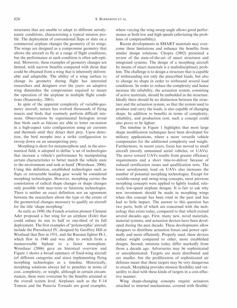
Ader proposed a bat wing for an airplane (Eole) thatcould reduce its size to half or one-third of its fulldeployment. The first examples of ‘polymorphic’ aircraftinclude the Pterodactyl IV, designed by Geoffrey Hill atWestland that flew in 1931, and the Russian fighter IS-1,which flew in 1940 and was able to switch from amaneuverable biplane to a faster monoplane.Weisshaar (2006) gave an historical overview andFigure 1 shows a broad summary of fixed-wing aircraft(of different categories and sizes) implementing flyingmorphing technologies as a timeline. Historically,morphing solutions always led to penalties in terms ofcost, complexity, or weight, although in certain circum-stances, these were overcome by the benefits attained atthe overall system level. Airplanes such as the F-14Tomcat and the Panavia Tornado are good examples,
where varying the wing sweep angle allows good perfor-mance at both low and high speeds (alleviating the prob-lems of compressibility).
Recent developments in SMART materials may over-come these limitations and enhance the benefits fromsimilar design solutions. Chopra (2002) presented areview of the state-of-the-art of smart structures andintegrated systems. The design of a morphing aircraftby means of smart materials is a multidisciplinary prob-lem. The challenge is to design a structure that is capableof withstanding not only the prescribed loads, but alsoto change its shape in order to withstand several loadconditions. In order to reduce the complexity and henceincrease the reliability, the actuation system, consistingof active materials, should be embedded in the structure.Ideally there should be no distinction between the struc-ture and the actuation system, so that the system used toproduce and carry the loads, is also capable of changingshape. In addition to benefits in terms of complexity,reliability, and production cost, such a concept couldalso prove to be lighter.
The timeline in Figure 1 highlights that most largeshape modification techniques have been developed formilitary applications, where a more versatile vehiclecompensates for the additional complexity and weight.Furthermore, in recent years, focus has moved to smallaircraft (mostly unmanned aerial vehicles, or UAVs).The move toward UAVs results from greater efficiencyrequirements and a short time-to-deliver because ofreduced certification issues and qualification tests. Thelower aerodynamic load on UAVs also increases thenumber of potential morphing technologies. Except forvariable-sweep and swing-wing concepts, most previousmorphing concepts were applied to lightly loaded, rela-tively low-speed airplane designs. It is fair to ask whynew investment should be made in morphing wingswhen this concept has been tried in the past and hashad so little impact. The answer to this question hastwo parts, both of which are concerned with the tech-nology that exists today, compared to that which existedseveral decades ago. First, many new, novel materials,material systems, and actuation devices have been devel-oped during the past decade. These developments allowdesigners to distribute actuation forces and power opti-mally and more efficiently. Properly used, these devicesreduce weight compared to other, more establisheddesigns. Second, missions today differ markedly fromthose a decade ago. Adversaries may be sophisticatedor unsophisticated. Targets are more distributed andare smaller, but the proliferation of sophisticated airdefenses mean that these targets may be very dangerousto attack. Morphing provides mission flexibility and ver-satility to deal with these kinds of targets in a cost-effec-tive manner.
Wing shape-changing concepts require actuatorsattached to internal mechanisms, covered with flexible/
824 S. BARBARINO ET AL.
sliding aerodynamic surfaces, together with load-trans-fer attachments between the skin and the skeleton. Thisrequires a distributed array of actuators, mechanisms,and materials that slide relative to each other or skinmaterials that stretch. Inman (2001) presented the actu-ator requirements for controlled morphing air vehicles.Mechanism design requirements include the range ofmotion, concerns about binding and friction, the effectsof wing structural deformability under load, and thecontrol of the actuator stroke under load. Actuator per-formance power and actuator force capability are essen-tial to design success. The size, weight, and volume ofthe actuators are important metrics, as are the range ofmotion, bandwidth, and fail-safe behavior. Locking isimportant when the wing is under load since, withoutlocking features, the actuators must withstand full load
unless the actuator works in parallel with a structuralelement. Morphing designs may also benefit from geo-metrically flexible structures if the aeroelastic energyfrom the airstream can be used to activate the shapechanging and tabs can maintain the shape using aero-elastic control. The wealth of new technologies availableto the wing designer provides intriguing design possibil-ities. Internal control and the strategy used to movefrom one wing form to another is also an importantdesign goal. This involves sensor selection, braking,and locking and the integration of sensors, actuators,and the associated software. The speed at which morph-ing shape change occurs is also important. While slowchanges may be sufficient to alter performance for somemissions, rapid changes may significantly increase air-craft maneuverability.
1903 1931 1931 1932 1937 1947 1951
1952 1964 1964 1966 1967 1967 1969
1970 1972 1974 1974 1979 1981 1985
1993 1994 2001 2002 2003 2004 2005
2006 2006 2007 2007 2007 2008 2010
Wright Flyer Pterodactyl IV MAK-10 IS-1 LIG-7 MAK-123 X 5Twist Sweep Span Bi-to monoplane Chord Span Sweep
XF10F F 111 XB 70 Su 17 IG MIG 23 SU 24 Tu 22 MSweep Sweep Span bending Sweep Sweep Sweep Sweep
F 14 FS 29 B 1 Tornado AD 1 Tu 160 AFTI/F 111Sweep Span Sweep Sweep Obliquing Sweep M.A.W.
FLYRT MOTHRA AAL F/A 18 Virginia Tech Univ. of Florida Univ. of FloridaSpan Camber Pitch A.A.W. Span Twist Gull
MFX 1 Univ. of Florida Virginia Tech Univ. of Florida MFX 2 Delft Univ. Virignia techSweep & Span Sweep Camber Folding Sweep & span Sweep Camber
Figure 1. Timeline of fixed wing aircraft implementing morphing technologies.
Morphing Aircraft 825
Rotary-wing aircrafts have challenged aeronauticalengineers with a plethora of issues to obtain stableflight. A major component of these issues is the complexflow field that a rotor blade is exposed to. Even in hover,each section of the rotor blade has different oncomingflow velocities, and engineers have designed the bladewith a pre-built twist to compensate for them.However, the optimum amount of this pre-twist varieswith the flight condition, and hence classical rotor bladedesigns are a compromise. Aside from the performanceissues, the rotor blades emanate a significant amount ofvibration and noise, caused by factors including theincreased asymmetrical loading of the rotor disc, andblade tip shocks that occur with increasing forwardspeed. Furthermore, the noise emitted by the rotorblades is compounded by the interaction of the bladeswith the tip vortices of the proceeding blades(blade!vortex interaction (BVI) noise) (Leishman,2006). These problems, while not necessarily imperativeto performance improvements, have to be solved inorder to obtain a smooth ride.This article focuses on structural, shape-changing
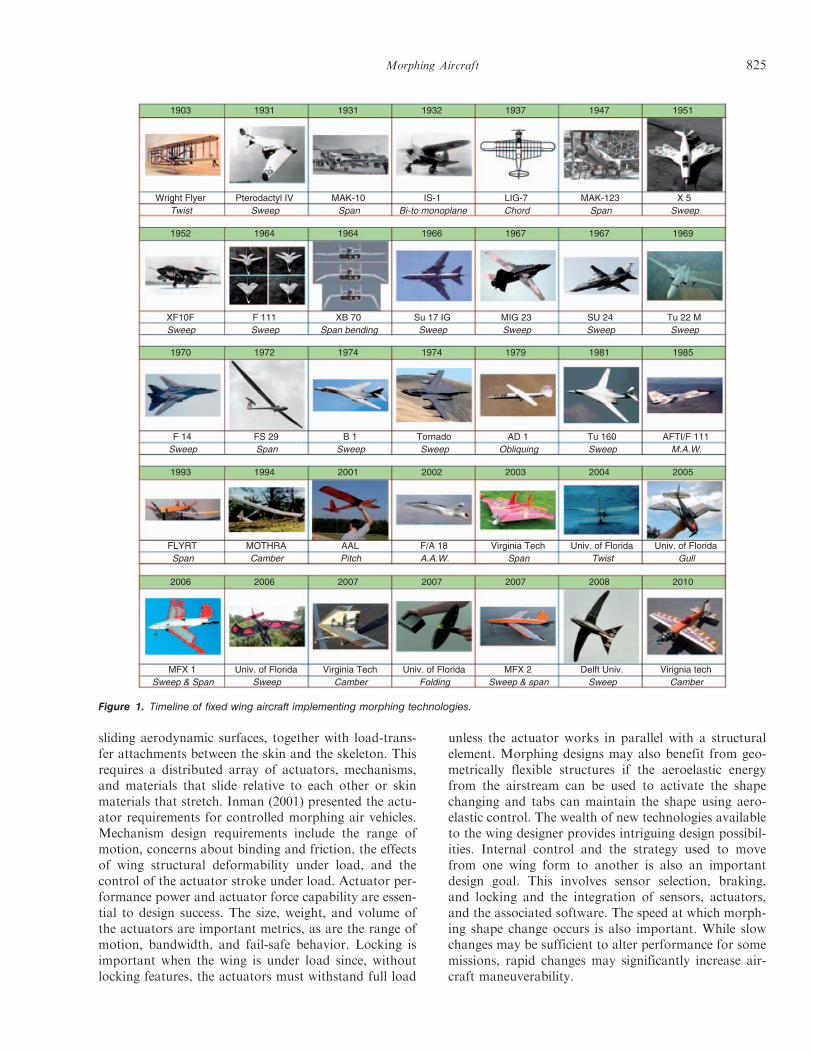
morphing concepts for both fixed and rotary wings,with particular reference to active systems (system char-acterized by an actuator). Thus, applications excludedfrom this study are those dealing with synthetic jets,vibration issues, and flight control, or belonging toother fields such as naval, automotive, or space.Inflatable solutions have been not considered. Thewing morphing concepts have been classified into threemajor types, as shown in Figure 2: planform alteration(involving span, chord, and sweep changes), out-of-plane transformation (twist, dihedral/gull, and span-wise bending), and airfoil adjustment (camber andthickness). For each geometrical parameter, a table sum-marizes the studies available in literature on that specifictopic, together with some useful information to give thereader an immediate picture of the developed work.However, some studies and past projects (for example,
the DARPA (2011) Morphing Adaptive Structure(MAS) program) combine several morphing variablesand are difficult to categorize. These works have beenreferenced in the section which best suits the principalaffected parameter.
In morphing applications, where large shape changesare expected, the design of a suitable skin is a huge chal-lenge and a key issue. The skin has to withstand theaerodynamic pressure loads, while being sufficientlycompliant for the underlying morphing structure. Thistopic will be discussed only briefly within this article.
BENEFITS OF MORPHING
The current use of multiple aerodynamic devices (suchas flaps and slats) represents a simplification of the gen-eral idea behind morphing. Traditional control systems(with fixed geometry and/or location) give high aerody-namic performance over a fixed range and for a limitedset of flight conditions. Outside of this range, these tra-ditional systems can be neutral or negatively influencethe aerodynamics and hence often give lower efficiency.Conventional hinged mechanisms are effective in con-trolling the airflow, but they are not efficient, as thehinges and other junctions usually create discontinuitiesin the surface, resulting in unwanted fluid dynamicphenomena.
Since 1920, airplanes have used devices that canincrease the lift during landing and takeoff (Renken,1985). Increases in aircraft weight and cruise speed,and increases in the wing structural stiffness to avoidmultiple aero-elastic phenomena (divergence, flutter,etc.) have led to the use of discrete control surfacessuch as ailerons and flaps in place of wing twist. Onlysince the late 1970s have researchers seriously revisitedconcepts of variable wing shape. Most of this researchwas based on two concepts, namely the active control ofthe curvature along the wingspan and the implementa-tion of flexible wings, able to exploit the aero-elasticforces to obtain the desired deformations (wingshapes). Many studies have targeted the variation ofthe wing shape (Weiss, 2003; Sofla et al., 2010) toachieve several objectives, such as the control of shockwaves during transonic flight conditions, or the controlof turbulence, the wake (laminar flow separation), vor-tices, active control of flutter, etc. (Stanewsky, 2001).
Civil and military aircrafts are designed to have opti-mal aerodynamic characteristics (maximum lift/dragratio) at one point and fuel condition in the entireflight envelope. However, the fuel loading and distribu-tion change continuously throughout the flight, and theaircraft may often have to fly at non-optimal flight con-ditions due to air traffic control restrictions. The conse-quent sub-optimal performance has more significancefor commercial aircraft as they are more flexible thanmilitary aircraft and also fuel efficiency has far greaterimportance as a performance measure. There is alsomuch recent interest in high-altitude long endurance(HALE) aircrafts that are designed to fly for severaldays. HALE aircrafts have a larger proportion of fuelweight than other aircrafts, and hence the resulting
Sha
pe m
orph
ing
win
g Planform Sweep Span Chord
Twist Dihedral/Gull
Spanwisebending
ThicknessCamber
Out-of-plane
Airfoil
Figure 2. Organization of the review.
826 S. BARBARINO ET AL.
changes in aeroelastic shape throughout the flight can besubstantial. Fuel efficiency is becoming increasinglyimportant for civil and HALE aircrafts, and anyapproach that enables better aerodynamic performancethroughout a flight needs to be investigated anddeveloped.Using an adaptive wing, whose geometry varies
according to changing external aerodynamic loads, theairflow in each part of the aircraft mission profile maybe optimized, resulting in an increase of aerodynamicperformance during cruise (Szodruch, 1985; Smith andNelson, 1990; Siclari et al., 1996; Martins and Catalano,1998) and maneuvers (Thornton, 1993). In the literature,the change in wing shape is also referred to as the mis-sion adaptive wing. Even a 1% reduction in airfoil dragwould save the US fleet of wide-body transport aircraft$140million/year, at a fuel cost of $0.70/gal (sourceNational Aeronautics and Space Administration(NASA) Dryden Studies). For a medium-range trans-port aircraft with an adaptive wing, the projected fuelsaving should be about 3!5%, depending on missiondistance.Large shape change concepts usually have associated
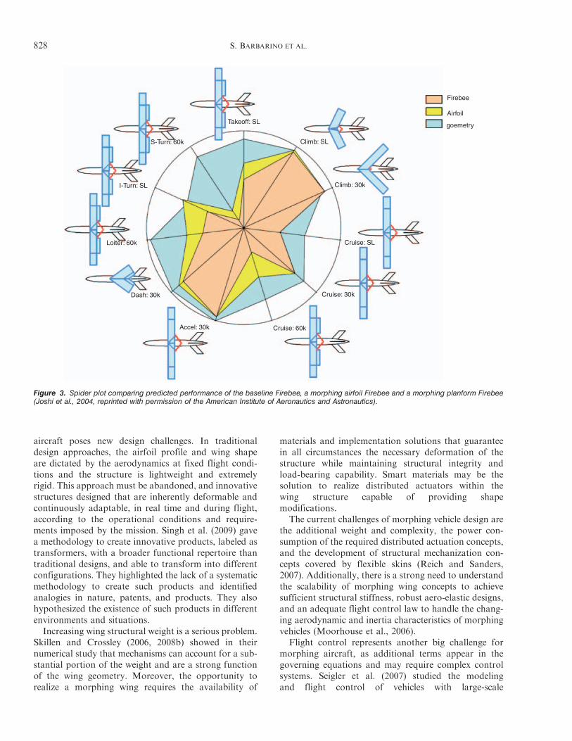
design penalties such as added weight or complexityand, without these penalties, morphing would alwaysmake sense. For most applications, there is a cross-over point where fuel penalties for not morphing beginto exceed the morphing weight penalty (Bowman et al.,2007). However, when overall system performance andmission requirements are assessed, large shape changeconcepts can be a viable approach for some missions,particularly those that combine several requirements interms of speed, altitude, or take-off and landing. Theadaptive wing would allow a given aircraft to performmultiple missions and enable a single aircraft with multi-role capabilities, radically expanding its flight envelope.From a military perspective, a single morphing aircraftcould perform different roles within a given mission thatotherwise would require different vehicles. Jha andKudva (2004) studied how changing wing parametersaffect the performance of an aircraft, and demonstratedthat an optimal design requires large geometric changesto satisfy a multi-role mission. Therefore, choosingbetween high efficiency or high maneuverability at thedesign stage would not be necessary. Aerodynamic opti-mization for a single flight condition would not be nec-essary. Compared to conventional aircraft, morphingaircrafts become more competitive as more missiontasks or roles are added to their requirements. Theimpact that a morphing wing has on aircraft perfor-mance for a range of flight conditions may be presentedgraphically using a radar (or spider) plot.Figure 3 shows a spider plot for 11 flight conditions,
where each axis of the plot represents the performancemetric associated with each flight condition. The outerradius of the spider plot indicates the best possible
performance. For a test case based on a BQM-34Firebee unmanned target drone aircraft (Joshi et al.,2004), the performance of the baseline aircraft can becompared to various wing morphing strategies on thespider plot. Planform morphing (a wing capable oftelescoping, chord extension, and variable sweep) signif-icantly improves the aircraft performance over that pro-vided by morphing the airfoil alone or by the baselineaircraft.
Many researchers follow a multidisciplinary optimiza-tion and systems approach to morphing solutions(Samareh et al., 2007), focusing on the integration ofcomputational fluid dynamics (CFD) and computa-tional structural dynamics models for geometric optimi-zation. Morphing wing airfoil and configurationgeometry, design methodology, effectors, flight control,aero-elasticity, and stability may also be considered(Rodriguez (2007) gave an overview). Bowman et al.(2007) demonstrated that for a hunter-killer mission,that is mainly cruise- and loiter-dominated, morphingdoes make sense (even with a 10% empty weight pen-alty), especially for vehicles under 20,000 lbs. For moredifficult missions, for example, increasing the searchradius, this break point in vehicle weight would increase.Roth et al. (2002) showed that morphing could have alarge impact on fleet size for a Coast Guard patrol mis-sion. The key to requirements for this mission was ahigh-altitude cruise out to station with a fast responsetime, and then a slow, low-altitude patrol.
Smith et al. (2007) investigated the benefits of morph-ing wing technology for fighter aircraft systems (withboth turbojet and turbofan propulsions), showing thatthe optimized mission-integrated designs yield signifi-cant fuel savings over fixed-wing aircraft. Mission seg-ment analysis shows that most fuel savings due tomorphing are obtained in the least-constrained (sub-sonic) flight segments.
Wittmann et al. (2009) gave a methodology to assessmorphing strategies and technologies for a wide range ofapplications, including civil and military, using a varietyof figures of merit to evaluate achievable benefits. Forinstance, a single degree-of-freedom variable-chordmorphing concept evaluated for a high-speed scenarioyielded 79% morphing efficiency for the maximumspeed as a figure of merit. An efficient transport scenariosaw a 23% improvement in lift-to-drag ratio when themorphing parameters were optimized simultaneously.For a high-lift scenario, a 74% increase in lift coefficientcould be achieved by maximizing wing area and camber.From a flight control perspective, the pitching momentis strongly influenced by wing sweep (and can lead to areduction of the trim surfaces), while roll and pitch con-trol can be efficiently modified by variable span (andalso variable twist).
Adaptive wings can provide a significant increase inperformance. However, the realization of such an
Morphing Aircraft 827
aircraft poses new design challenges. In traditionaldesign approaches, the airfoil profile and wing shapeare dictated by the aerodynamics at fixed flight condi-tions and the structure is lightweight and extremelyrigid. This approach must be abandoned, and innovativestructures designed that are inherently deformable andcontinuously adaptable, in real time and during flight,according to the operational conditions and require-ments imposed by the mission. Singh et al. (2009) gavea methodology to create innovative products, labeled astransformers, with a broader functional repertoire thantraditional designs, and able to transform into differentconfigurations. They highlighted the lack of a systematicmethodology to create such products and identifiedanalogies in nature, patents, and products. They alsohypothesized the existence of such products in differentenvironments and situations.Increasing wing structural weight is a serious problem.
Skillen and Crossley (2006, 2008b) showed in theirnumerical study that mechanisms can account for a sub-stantial portion of the weight and are a strong functionof the wing geometry. Moreover, the opportunity torealize a morphing wing requires the availability of
materials and implementation solutions that guaranteein all circumstances the necessary deformation of thestructure while maintaining structural integrity andload-bearing capability. Smart materials may be thesolution to realize distributed actuators within thewing structure capable of providing shapemodifications.
The current challenges of morphing vehicle design arethe additional weight and complexity, the power con-sumption of the required distributed actuation concepts,and the development of structural mechanization con-cepts covered by flexible skins (Reich and Sanders,2007). Additionally, there is a strong need to understandthe scalability of morphing wing concepts to achievesufficient structural stiffness, robust aero-elastic designs,and an adequate flight control law to handle the chang-ing aerodynamic and inertia characteristics of morphingvehicles (Moorhouse et al., 2006).
Flight control represents another big challenge formorphing aircraft, as additional terms appear in thegoverning equations and may require complex controlsystems. Seigler et al. (2007) studied the modelingand flight control of vehicles with large-scale
Takeoff: SL
S-Turn: 60k
I-Turn: SL
Loiter: 60k
Dash: 30k
Accel: 30k Cruise: 60k
Cruise: 30k
Cruise: SL
Climb: 30k
Climb: SL
Firebee
Airfoil
goemetry
Figure 3. Spider plot comparing predicted performance of the baseline Firebee, a morphing airfoil Firebee and a morphing planform Firebee(Joshi et al., 2004, reprinted with permission of the American Institute of Aeronautics and Astronautics).
828 S. BARBARINO ET AL.
planform changes. The equations of atmospheric flightwere derived in a general form, methods to integrate theaerodynamic forces examined, and various approachesand methods of flight control distinguished.The absence of sharp edges and deflected surfaces on
morphing aircraft also has the potential to reduce theradar signature and visibility of the vehicle, thus enhanc-ing its stealth properties. Gern et al. (2005) highlightedthat redundancy generally requires a conventional flapto be connected to at least one or two additional actu-ators to provide sufficient flight control in case of air-frame damage or actuator failure. This maydramatically increase the power installed in a vehicle;for instance, the B-2 stealth bomber has 24 actuatorsto drive 11 primary control surfaces. In contrast, morph-ing wings usually have heavily distributed actuation thatprovides sufficient robustness and redundancy toaccount for actuator failures with only a negligibleeffect on weight.Current research on rotary wings focuses on improve-
ments in terms of increased speed, payload, and maneu-verability, along with reductions in costs, vibrations, andnoise. The DARPA Mission Adaptive Rotor (MAR)initiative (Warwick, 2009) plan to fly an adaptive rotorby 2018. Boeing, Sikorsky, and the Bell Boeing tiltrotorteam have received 16-month Phase 1 contracts to assessa wide range of adaptive rotor technologies and developdesigns for both a completely new rotor system and aretro-fit demonstrator rotor. The goal of the MAR proj-ect is a rotor that can change its configuration before amission and in flight, between mission segments andwith every revolution. DARPA has identified a widerange of potential approaches to reconfigure the rotorin flight, including varying the blade diameter, sweep,and chord; morphing tip shapes and variable-camberairfoils; varying blade twist, anhedral/dihedral, tipspeed, stiffness, and damping. DARPA is looking fortechnologies that can increase rotorcraft payload by30% and range by 40%, while reducing the acousticdetection range by 50% and vibration by 90% overfixed geometry rotors. Some studies demonstrate theaerodynamic and acoustic benefits of an active twistrotor (Bailly and Delrieux, 2009; Boyd and Douglas,2009; Zhang and Hoffmann, 2009), rotor power reduc-tion using trailing-edge flaps (Leon and Gandhi, 2009)and envelope expansion using extendable chord sections(Leon et al., 2009). This article only includes morphingapplications with performance objectives.
MORPHING SKINS
Most of the morphing technologies or conceptsassume the existence of an appropriate flexible skin.The design of flexible skins is challenging and hasmany conflicting requirements. The skin must be softenough to allow shape changes but at the same time it
must be stiff enough to withstand the aerodynamic loadsand maintain the required shape/profile. This requiresthorough trade-off design studies between the require-ments. In addition, the type of flexible skin requireddepends on the loading scenario and the desiredchange in shape (one-dimensional or multi-dimen-sional). Therefore, the design of flexible skins dependson the specific application.
Thill et al. (2008) performed a comprehensive reviewof flexible skins and considered various novel materialsystems concepts and technologies. Only papers pub-lished since this review are briefly described here. Thillet al. (2010) investigated the use of a composite corru-gated structure as morphing skin panels in the trailing-edge region to vary the camber and chord of an airfoil.Wereley and Gandhi (2010) examined extensively thechallenges and requirements of flexible skins and listedthe state-of-the-art solutions. Skin concepts includingelastomeric matrix composites have been investigatedfor large area changes (Peel et al., 2009; Bubert et al.,2010; Murray et al., 2010, Olympio et al., 2010).Furthermore, the use of morphing core sandwich struc-tures covered by compliant face sheet has been investi-gated for both low- and for high-strain applicationsdepending on the cellular arrangement and the materialof the core (Joo et al., 2009; Bubert et al., 2010, Olympioand Gandhi, 2010a, b). In addition, McKnight et al.(2010) studied the use of segmented reinforcement (dis-crete) to create a variable-stiffness material that can beadopted as a flexible skin.
WING PLANFORM MORPHING
Wing planform is mainly affected by three parameters(individually or in combination): span, chord, andsweep. Both span and sweep can affect the wing aspectratio, a parameter that modifies the lift-to-drag ratio.Thus, an increase in wing aspect ratio would result inan increase in both range and endurance (Anderson,2000). From an aerodynamic perspective, the changein aspect ratio produces differences in lift curve slopeand forces due to the change in the wing area. From adynamics perspective, the inertia of the aircraft alsochanges. Span and sweep morphing have been investi-gated for military applications, particularly for UAVs,which must loiter during surveillance and rapidly switchinto high-speed dash mode to move reconnaissance areaor to attack a target. Chord morphing has mainly beenapplied to helicopter rotor blades so far. The objectiveof the DARPA MAS program was to design and builtactive, variable-geometry wing structures with the abilityto change wing shape and wing area substantially. Allthree MAS contractors (Lockheed Martin, Hypercomp/NextGen, and Raytheon Missile Systems) conducted afunctional analysis that concluded that changing wing
Morphing Aircraft 829
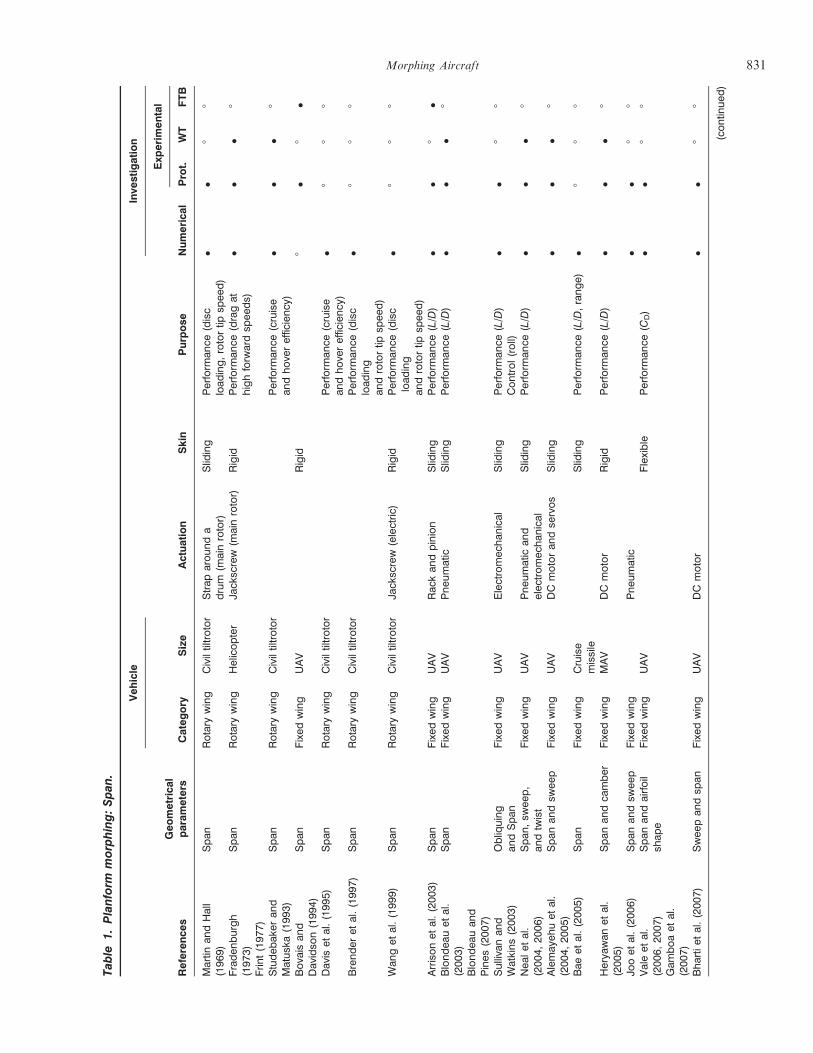
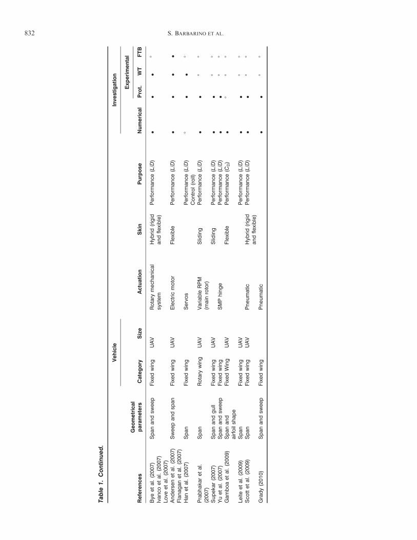
planform area and wingspan were the primary enablersof a new class of morphing air vehicles.Tables 1!3 summarize the literature for each geomet-
rical parameter. However, due to the intrinsically cou-pled nature of many applications of planform change,some papers appear in more than one table.
Variable Span for Fixed Wing Aircraft
Wings with large spans have good range and fuel effi-ciency, but lack maneuverability and have relatively lowcruise speeds. By contrast, aircrafts with low-aspectratio wings are faster and highly maneuverable, butshow poor aerodynamic efficiency (McCormik, 1995).A variable-span wing can potentially integrate into asingle aircraft the advantages of both designs, makingthis emerging technology especially attractive for mili-tary UAVs. Increasing the wingspan increases the aspectratio and wing area and decreases the span-wise lift dis-tribution for the same lift. Thus, the drag of the wingdecreases, and consequently, the range of the vehicleincreases. Unfortunately, the wing-root bendingmoment can increase considerably due to the longerspan. Thus, both the aerodynamic and the aeroelasticcharacteristics should be investigated in the design ofvariable-span morphing wings.Most span morphing concepts are based on a tele-
scopic mechanism, following the ideas of the Russianexpatriate Ivan Makhonine, where the wing outerpanel telescoped inside the inner panel to enable spanand wing area changes. The MAK-10 was the firstdesign with a telescopic wing and it first flew in 1931.The mechanism was powered pneumatically and enabledspan increased up to 62% (from 13 to 21m) and areaincreased up to 57% (from 21 to 33m2) (Weisshaar,2006).The US Department of Defense has designed numer-
ous vehicle configurations in the past 20 years to meetvarious mission objectives. Bovais and Davidson (1994)from the Naval Research Laboratory built an experi-mental non-recoverable ship-launched expendableradar decoy named FLYRT (Flying Radar Target)that was first flown in September 1993. FLYRT waslaunched with rigid folded wings and tail surfaces froman MK 36 launcher using a solid-propellant rocketmotor which burned for about 1.6 s. The fully expandedrigid wing had a span of 2.4m and weighed 60 kg.Immediately after launch, the tail fin unfolded mechan-ically to control the vehicle during ascent. A total of 13drones were built before the program ended, and thedecoy successfully demonstrated the defense of a varietyof ships against simulated radar threats.Gevers Aircraft Inc. (1997) investigated a telescopic
wing, capable of variable span, for use on a six-seatamphibious aircraft. The wing was composed of afixed center section and two extendable outer sections,
using an overlapping extension spar system. The centersection was a high-speed wing (low drag and strong) andthe completely retractable high-lift section moved in thespan-wise direction.
The morphing unmanned aerial attack vehicle, devel-oped by AeroVisions Inc. (2011; Website) within theMorphing Aircraft Structures program funded byDARPA, consisted of several sliding segments. Thewingspan was inversely proportional to the cruisespeed, and allowed for several operating conditionsfrom loitering to fast cruise to high-speed attack.
Bae et al. (2005) performed both static aerodynamicand aeroelastic studies on the wing of a long-rangecruise missile and highlighted some of the benefits andchallenges associated with the design of a morphingwing capable of span change. The total drag of themorphing wing decreased by approximately 25%, andthe range increased by approximately 30%. The aero-elastic analysis showed that the flexibility of the morph-ing wing structure increased as the wingspan increased.At a given flight condition, the deformation from theaerodynamic loads was much larger than that of theconventional wing. Static aeroelastic considerationsshowed that a variable-span wing requires increasedbending stiffness because the bending deformation ismore significant than twist.
The Air Force Research Laboratory (2011; AFRL)Vehicle Research Section (Website) developed anunmanned planform called ALICE (Air LaunchedIntegrated Counter-measure, Expendable) that can beair launched from a tactical aircraft at speeds up toMach 0.8 and altitudes up to 45,000 ft. After launch,ALICE glides using tail control surfaces until it reachesa speed of 250 knots. The rigid wing and propeller thendeploy and the heavy fuel engine starts. ALICE willcruise approximately 200 nautical miles in 1 h beforethe outer rigid wing panels deploy for loiter. Researchadvances included the development of the polymorphicwing, a JP-8 fueled rotary engine, a high-efficiency star-ter/generator, a folding variable-pitch propeller, and anadvanced EW payload.
Arrison et al. (2003) modified a Delta Vortex RC air-craft by adding telescopic wings. The new vehicle,renamed BetaMax, could increase wingspan by 10 in.(over a 43.5 in. basic span). A range increase of 19%over the conventional aircraft was predicted, allowingfor the increased weight. The RC vehicle was success-fully flown, and it highlighted a change in static stabilitybetween the retracted and extended case of nearly 5%.Neal et al. (2004) designed and demonstrated a variable-planform aircraft capable of large wing planformchanges, both in sweep and span, using a telescopicpneumatic actuator. The aspect ratio could change upto 131% through combined span and sweep, while wingarea could change by 31%. Wind tunnel results showedthat only three planform geometries were required to
830 S. BARBARINO ET AL.
Table
1.Planform
morphing:Span
.
Reference
sGeometrical
param
eters
Vehicle
Actuation
Skin
Purpose
Inve
stigation
Category
Size
Numerica
l
Exp
erimental
Prot.
WT
FTB
Martin
andHall
(196
9)Span
Rotary
wing
Civiltiltrotor
Strap
arounda
drum
(mainrotor)
Slid
ing
Perform
ance
(disc
load
ing,rotortip
spee
d)
!!
88
Fraden
burgh
(197
3)Frin
t(197
7)
Span
Rotary
wing
Helicopter
Jack
screw
(mainrotor)
Rigid
Perform
ance
(dragat
highforw
ardsp
eeds)
!!
!8
Studeb
aker
and
Matusk
a(199
3)Span
Rotary
wing
Civiltiltrotor
Perform
ance
(cruise
andhove
refficiency
)!
!!
8
Bova
isan
dDav
idso
n(199
4)Span
Fixed
wing
UAV
Rigid
8!
8!
Dav
iset
al.(199
5)Span
Rotary
wing
Civiltiltrotor
Perform
ance
(cruise
andhove
refficiency
)!
88
8
Brender
etal.(199
7)Span
Rotary
wing
Civiltiltrotor
Perform
ance
(disc
load
ing
androtortip
spee
d)
!8
88
Wan
get
al.(199
9)Span
Rotary
wing
Civiltiltrotor
Jack
screw
(electric
)Rigid
Perform
ance
(disc
load
ing
androtortip
spee
d)
!8
88
Arrisonet
al.(200
3)Span
Fixed
wing
UAV
Rac
kan
dpinion
Slid
ing
Perform
ance
(L/D
)!
!8
!Blondea
uet
al.
(200
3)Blondea
uan
dPines
(200
7)
Span
Fixed
wing
UAV
Pneu
matic
Slid
ing
Perform
ance
(L/D
)!
!!
8
Sulliva
nan
dWatkins(200
3)Obliq
uing
andSpan
Fixed
wing
UAV
Electromec
han
ical
Slid
ing
Perform
ance
(L/D
)Control(roll)
!!
88
Nea
let
al.
(200
4,20
06)
Span
,sw
eep,
andtw
ist
Fixed
wing
UAV
Pneu
matic
and
elec
tromec
han
ical
Slid
ing
Perform
ance
(L/D
)!
!!
8
Alemay
ehuet
al.
(200
4,20
05)
Span
andsw
eep
Fixed
wing
UAV
DC
motoran
dse
rvos
Slid
ing
!!
!8
Bae
etal.(200
5)Span
Fixed
wing
Cruise
missile
Slid
ing
Perform
ance
(L/D
,range)
!8
88
Herya
wan
etal.
(200
5)Span
andca
mber
Fixed
wing
MAV
DC
motor
Rigid
Perform
ance
(L/D
)!
!!
8
Jooet
al.(200
6)Span
andsw
eep
Fixed
wing
Pneu
matic
!!
88
Valeet
al.
(200
6,20
07)
Gam
boaet
al.
(200
7)
Span
andairfoil
shap
eFixed
wing
UAV
Flexible
Perform
ance
(CD)
!!
88
Bhartiet
al.(200
7)Swee
pan
dsp
anFixed
wing
UAV
DC
motor
!!
88
(contin
ued
)
Morphing Aircraft 831
Table
1.Continued.
Reference
sGeometrical
param
eters
Vehicle
Actuation
Skin
Purpose
Inve
stigation
Category
Size
Numerica
l
Exp
erimental
Prot.
WT
FTB
Bye
etal.(200
7)Ivan
coet
al.(200
7)Lo
veet
al.(200
7)
Span
andsw
eep
Fixed
wing
UAV
Rotary
mec
han
ical
system
Hyb
rid(rigid
andfle
xible)
Perform
ance
(L/D
)!
!!
8
Anderse
net
al.(200
7)Flanag
anet
al.(200
7)Swee
pan
dsp
anFixed
wing
UAV
Electric
motor
Flexible
Perform
ance
(L/D
)!
!!
!
Han
etal.(200
7)Span
Fixed
wing
Servo
sPerform
ance
(L/D
)Control(roll)
8!
!8
Prabhak
aret
al.
(200
7)Span
Rotary
wing
UAV
Variable
RPM
(mainrotor)
Slid
ing
Perform
ance
(L/D
)!
!8
8
Supek
ar(200
7)Span
andgull
Fixed
wing
UAV
Slid
ing
Perform
ance
(L/D
)!
!8
8Yuet
al.(200
7)Span
andsw
eep
Fixed
wing
SMPhinge
Perform
ance
(L/D
)!
!8
8Gam
boaet
al.(200
9)Span
and
airfoilsh
ape
Fixed
Wing
UAV
Flexible
Perform
ance
(CD)
!8
88
Leite
etal.(200
9)Span
Fixed
wing
UAV
Perform
ance
(L/D
)!
!8
8Sco
ttet
al.(200
9)Span
Fixed
wing
UAV
Pneu
matic
Hyb
rid(rigid
andfle
xible)
Perform
ance
(L/D
)!
!8
8
Grady(201
0)Span
andsw
eep
Fixed
wing
Pneu
matic
!!
88
832 S. BARBARINO ET AL.
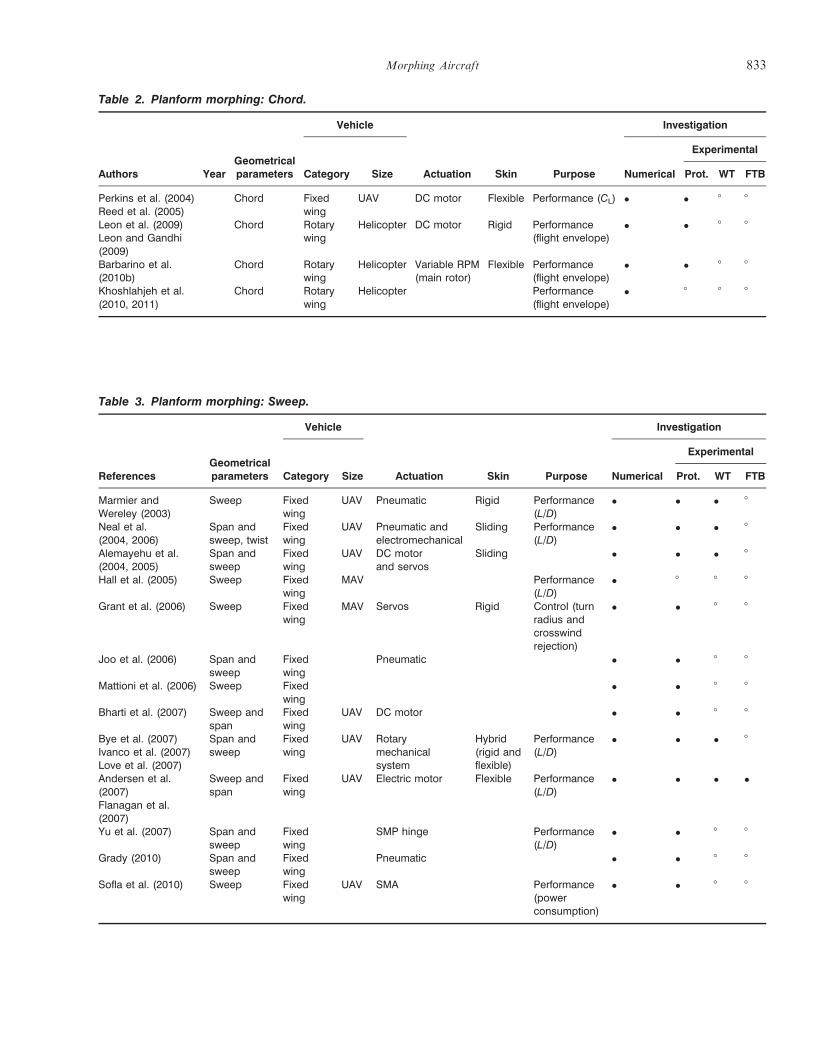
Table 3. Planform morphing: Sweep.
ReferencesGeometricalparameters
Vehicle
Actuation Skin Purpose
Investigation
Category Size Numerical
Experimental
Prot. WT FTB
Marmier andWereley (2003)
Sweep Fixedwing
UAV Pneumatic Rigid Performance(L/D)
! ! ! 8
Neal et al.(2004, 2006)
Span andsweep, twist
Fixedwing
UAV Pneumatic andelectromechanical
Sliding Performance(L/D)
! ! ! 8
Alemayehu et al.(2004, 2005)
Span andsweep
Fixedwing
UAV DC motorand servos
Sliding ! ! ! 8
Hall et al. (2005) Sweep Fixedwing
MAV Performance(L/D)
! 8 8 8
Grant et al. (2006) Sweep Fixedwing
MAV Servos Rigid Control (turnradius andcrosswindrejection)
! ! 8 8
Joo et al. (2006) Span andsweep
Fixedwing
Pneumatic ! ! 8 8
Mattioni et al. (2006) Sweep Fixedwing
! ! 8 8
Bharti et al. (2007) Sweep andspan
Fixedwing
UAV DC motor ! ! 8 8
Bye et al. (2007)Ivanco et al. (2007)Love et al. (2007)
Span andsweep
Fixedwing
UAV Rotarymechanicalsystem
Hybrid(rigid andflexible)
Performance(L/D)
! ! ! 8
Andersen et al.(2007)Flanagan et al.(2007)
Sweep andspan
Fixedwing
UAV Electric motor Flexible Performance(L/D)
! ! ! !
Yu et al. (2007) Span andsweep
Fixedwing
SMP hinge Performance(L/D)
! ! 8 8
Grady (2010) Span andsweep
Fixedwing
Pneumatic ! ! 8 8
Sofla et al. (2010) Sweep Fixedwing
UAV SMA Performance(powerconsumption)
! ! 8 8
Table 2. Planform morphing: Chord.
Authors YearGeometricalparameters
Vehicle
Actuation Skin Purpose
Investigation
Category Size Numerical
Experimental
Prot. WT FTB
Perkins et al. (2004)Reed et al. (2005)
Chord Fixedwing
UAV DC motor Flexible Performance (CL) ! ! 8 8
Leon et al. (2009)Leon and Gandhi(2009)
Chord Rotarywing
Helicopter DC motor Rigid Performance(flight envelope)
! ! 8 8
Barbarino et al.(2010b)
Chord Rotarywing
Helicopter Variable RPM(main rotor)
Flexible Performance(flight envelope)
! ! 8 8
Khoshlahjeh et al.(2010, 2011)
Chord Rotarywing
Helicopter Performance(flight envelope)
! 8 8 8
Morphing Aircraft 833
maintain minimum drag over a range of possible liftcoefficients. Neal et al. (2006) redesigned the vehicle toimplement a variable-geometry tail and increased thestrength of the structure and mechanisms.Blondeau et al. (2003) designed and fabricated a three-
segmented telescopic wing for a UAV. Hollow fiberglassshells were used to preserve the span-wise airfoil geom-etry and insure compact storage and deployment of thetelescopic wing. To reduce the weight, they replaced thewing spars with inflatable actuators that could supportthe aerodynamic loads on the wing. Their telescopic spardesign consisted of three concentric circular aluminumtubes of decreasing diameter and increasing length, con-nected by ceramic linear bearings, and deployed andretracted using input pressure. The wing could undergoa 114% change in the aspect ratio, while supportingaerodynamic loads. Wind tunnel test results showedthat the wing suffered from parasitic drag created bythe seams of the wing sections. Fully deployed the tele-scopic wing achieved lift-to-drag ratios as high as 9 to10, which is approximately 25% lower than its rigidfixed wing counterpart. In a further development,Blondeau and Pines (2007) adopted two identical tele-scopic spars instead of one, mechanically coupled by theribs, to prevent wing twist and fluttering. The new pro-totype could undergo a 230% change in aspect ratio,and seam heights were reduced giving less parasiticdrag. In its fully deployed condition, the telescopicwing could achieve lift-to-drag ratios as high as 16,which was similar to its solid foam-core wingcounterpart.Supekar (2007) evaluated the structural and aerody-
namic performance of a two-segment telescopic wing fora UAV that could also undergo variable dihedral of theouter wing. Although a crude prototype was manufac-tured, no successful actuation of the mechanism wasreported due to the fabrication problems. Sullivan andWatkins (2003) investigated an oblique wing aircraft (anaircraft capable of rotating its wing around a centralpivot) that was capable of symmetric and asymmetricspan extensions. With only symmetric span extension,the aspect ratio could change between 3.3 and 4.7, lead-ing to an increase in stall and cruise speed (approxi-mately 30%) and an increase in take-off ground roll(100% increase). The Virginia Tech Morphing WingTeam (Alemayehu et al., 2005) developed a morphingwing with three different morphing characteristics:change in span, sweep angle, or chord length.Heryawan et al. (2005) designed an expandable
morphing wing for a micro-aerial vehicle (MAV) basedon a typical bird wing. The wing was divided into tworigid parts (made of carbon composite and balsa at theleading edge, and carbon fiber composite mimickingwing feathers on the remaining part); the outer wingwas driven by a small direct current (DC) motor throughreinforced composite linkages. The wing was able to
change aspect ratio from 4.7 to 8.5 in 2 s. Additionally,two lightweight piezo-composite actuators (LIPCAs)were attached under the inner wing to modify camber.Wind tunnel tests carried out for a 7.5m/s wind speed(Re " 30,000) and at angles of attack between 0# and 8#
showed that the total drag decreased significantly (morethan 10%) during wing expansion while the lift morethan trebled. The maximum value of lift-to-drag ratiooccurred at 2# angle of attack for the low-aspect ratioconfiguration, in contrast to 0# for the high-aspectratio configuration. Finally, the actuation of the twoLIPCAs produced an additional 16% lift.
Han et al. (2007) performed wind tunnel tests on amodel with telescopic wings actuated by two separateservomotors to study the effect of variable aspect ratioon wing-in-ground effect vehicles operating inside achannel. Changing the aspect ratio from 3.2 to 3.5improved the lift-to-drag ratio more than the effect ofboth the ground and the sidewalls. Span changing alsohad a bigger advantage with walls present (up to 54.7%lift-to-drag increase compared to the original wing).Wing tip extension does not control rolling moment effi-ciently on its own, but the influence of the ground orsidewall effects generates a positive rolling moment dueto the high-pressure air trapped between the lower sur-face of the wing and the ground (or sidewall).
An alternative approach to changing wingspan uses ascissor-like mechanism for the wingbox. Joo et al. (2006)studied the optimal location of a distributed network ofactuators within such a mechanism. Their reconfigur-able wingbox was constructed of four-bar mechanismswith rigid links, and an experiment was conducted on asingle cell linkage using a pneumatic actuator. An opti-mization analysis was performed to select the optimalactuator placement. Springs were used in their design toaccount for a stretchable skin, but a parametric study ofthe compliance was not performed. Johnson et al. (2009)further developed this work by exploring the effect ofthe optimal actuator placement and position on energyefficiency in morphing wings. Bharti et al. (2007)explored a scissor-mechanism to alter the aircraft spanand sweep with a design based on the TSCh wing(NextGen Aeronautics Inc.). A scale prototype mecha-nism was constructed that achieved a 55% span change.
Vale et al. (2006, 2007) and Gamboa et al. (2007)designed a wing section capable of independent changesof span and airfoil chord and shape by the use of extend-able ribs and spars. They compared the performanceachievable with such a morphing wing, in terms of min-imum drag, to a traditional fixed wing at different flightspeeds (15!50m/s). An aero-structural analysis was per-formed, considering a mechanism that could expand inthe span-wise direction, keeping the ribs evenly distrib-uted, and increasing the chord using the ribs. The skinwas assumed to be rubber, wrapped as a sleeve aroundthe wing internal mechanism and structure, with
834 S. BARBARINO ET AL.
some pre-tension. However, the aerodynamic loadsacting on the skin, and airfoil thickness and area,reduce between consecutive ribs (where it is unsup-ported), leading to a non-optimal shape that also affectsparasitic drag (for instance, at 30m/s, the reduction indrag is 22.5% when compared to the non-morphingwing). The final design was also heavy due to the servo-motors, transmission components, and other equip-ments; moreover, the torque actuation requirements forthe chord expansion mechanism were prohibitive.Gamboa et al. (2009) proposed new structural designsfor chord and span extension, but no prototype resultsare available.Leite et al. (2009) further investigated the concept of a
telescopic wing with airfoil shape change capability,although their prototype had only span change. The air-foil change was assumed to be between two different andspecific airfoils (Eppler 434 and NACA 0012). The cou-pled aero-structural analysis studied the optimal combi-nation of morphing parameters within a typical missionprofile for a proposed remote piloted vehicle, producingan optimum morphing wing polar curve that outper-formed the original vehicle in terms of extra take-offweight and lower drag at all speeds.Scott et al. (2009) developed a novel low-stored volume
wing for a HALE aircraft using a hybrid design incorpo-rating a telescoping and load-bearing spar within aninflatable wing. The primary benefits include signifi-cantly lower required inflation pressures and loweroverall system weight. The overall goal was to developa low-stored volume wing design with a projected vehiclelift-to-drag ratio greater than 27 at altitudes ranging from60,000 to 75,000 ft. The sequence from initial ballisticdelivery to complete vehicle deployment is as follows:the aircraft is separated from a rocket in the stowed posi-tion either by mechanical means or a parachute; the taildeploys and the rigid wing rotates 90# to provide a stablecraft capable of weathering the deployment dynamics;the span extensions deploy, giving the vehicle four timesthe span of the stowed rigid wing. The design of high-aspect-ratio wings is driven by the ability to sustain sub-stantial root bending moments: to bear these bendingmoments with a purely inflatable wing would requirevery high (50!100 psi) pressurization causing problemsspecifying the skin fabric and in vehicle certification.The hybrid approach utilizes ‘ribfoils’ and tension wiresto support the skin, thereby reducing the chamber pres-sure to the minimum required to maintain the airfoil pro-file. The telospar (hybrid structural actuator) serves asthe primary load path as the wing section is deployed,and this concept has proven viable in a series of deploy-ment tests, in ambient and vacuum conditions. System-level studies concluded that this deployed span designwould reduce pressurization requirements by almost anorder of magnitude, and reduce wing weight by 25!35%(compared to a purely inflatable vectran-baffled wing).
The most dramatic morphing wing involving spanchange that has been realized as a wind tunnel prototypeis the Agile Hunter by Lockheed Martin (Bye andMcClure, 2007; Ivanco et al., 2007; Love et al., 2007).Funded by DARPA within the MAS program, the pro-totype (also called a Z-wing) was based on a militaryUAV capable of folding the inner sections of the wingnear to the fuselage to reduce the surface area and dragduring transonic flight at low altitude. The major chal-lenge was the realization of suitable hinges that connectthe two wing portions; the hinges have to sustain theaerodynamic loads but offer a smooth, continuous aero-dynamic surface. Several materials were considered,including silicone-based and shape memory polymer(SMP) skins. Wind tunnel tests at Mach 0.6 showed amorphing capability from 0# to 130# over 65 s with acontrollable, reliable, and precise actuation.
Asymmetrical span morphing can be used for rollcontrol. Henry and Pines (2007) extended the standardaircraft dynamics model to include the additional terms(as perturbations) due to morphing and demonstratedthat asymmetrical span morphing was effective for rollcontrol. The total damping in the system increased whenthe span extension rate was positive (span increase) dueto the conservation of angular momentum. Span exten-sion induces a roll damping moment that is greater thanthat due to aileron deflection.
Seigler et al. (2004) also investigated asymmetricalspan extension for increased maneuverability of bank-to-turn cruise missiles. By formulating a full non-linearmodel of the missile, due to the shift of the missile’scenter of mass and the dependence of the rollingmoment on the angle of attack, they showed that thecontrol authority can be significantly larger when com-pared to conventional tail surface control. Improvedmaneuverability, however, is highly dependent on theangle of attack, linear actuation speed, and extensionlength. Moreover, as the mass of the extending wingsbecomes large relative to the missile body, the rigidbody dynamics can become increasingly complex. Thepaper presented a non-linear control law to control theroll, angle of attack, and sideslip angles in accordancewith bank-to-turn guidance. The control method provedto be adept in tracking-commanded inputs while effec-tively eliminating sideslip.
Variable Span for Rotary-Wing Aircraft
The variable-diameter rotor (VDTR) is not a newconcept. In the late 1960s, the telescoping rotor aircraft(TRAC) rotor system was designed and tested for use instowed rotor and compound helicopter applications.For stowed rotors, the design alleviated dynamic andstrength problems associated with stopping a rotorduring flight, while for compound helicopters, thedesign reduced drag at high forward speeds.
Morphing Aircraft 835
The TRAC rotor used a jackscrew mechanism to slidean outer blade section over an inner aerodynamicallyshaped tube. Wind tunnel tests and actuator mechanismcycle tests demonstrated the performance benefits andthe feasibility of the concept (Fradenburgh, 1973; Frint,1977). Prabhakar et al. (2007) used the inherent centrif-ugal force for actuation, reducing power requirementsand mechanical complexity. The span extensionincreases with rotor speed and the amount is calibratedduring the design phase. A scaled prototype was builtand tested.VDTRs could solve many of the technical problems
that arise in large civil tiltrotors. The rotors couldchange diameter in flight, so that a large diameter (heli-copter size) rotor is used in hover and a smaller diameter(propeller size) rotor is used in cruise (Brender et al.,1997). The low disc loading in hover and low tipspeeds in cruise made possible by the diameter changecould eliminate many of the undesirable conventionaltiltrotor attributes (Fradenburgh and Matuska, 1992).Low-disc loading tiltrotor designs have many of theadvantages of helicopters during vertical flight includinglow power requirements (as much as 30% lower for theVDTR), low downwash velocities, good autorotationperformance, and reduced BVI noise during descent.The advantages of the VDTR during cruise are derivedfrom the low rotor tip speeds made possible by the smalldiameter. Low tip speeds reduce compressibility dragand lead to higher blade loading during cruise. Bothfactors contribute significantly to rotor propulsive effi-ciency (lower fuel consumption). Moreover, the VDTR,in contrast to conventional tiltrotors, does not requirerotor speed reduction for efficient cruise flight as thenecessary tip speed reduction may be obtained by reduc-ing the rotor diameter. Other important advantages arereduced gust response due to higher blade loading andreduced internal cabin noise levels (i.e., improved pas-senger comfort) due to low tip speeds and large rotor tipdistance from the fuselage. However, the diameterchange mechanism adds weight and complexity to therotor system.Martin and Hall (1969) describe a VDTR concept
developed specifically for a tiltrotor aircraft. The outerblade sections of this design telescoped into the innerblade section and were actuated using a strap woundaround a drum attached to the drive shaft. A 25-ft diam-eter version of this rotor design demonstrated 700 exten-sions and retractions during ground tests.Studebaker and Matuska (1993) performed a reduced-
scale wind tunnel test of a rotor designed for a 38,600 lbaircraft with a 36-passenger payload. This test used a 1/6scale semi-span model to demonstrate the aeroelasticperformance of the VDTR converting from hover tocruise. No instabilities encountered in any flight mode.The test also verified that the rotor root cut out had onlya small effect on the hover figure of merit and that the
VDTR had improved gust response characteristics overconventional designs. The baseline VDTR design waslater modified to incorporate NASA Short Haul (CivilTiltrotor) guidelines.
Davis et al. (1995) developed a dual-point optimizerto simultaneously optimize the rotor design for hoverand cruise, based on the EI-IPIC/HERO (Evaluationof Hover-Performance using Influence Coefficients/Helicopter Rotor Optimizer) design tool. Several designsshowed significantly higher cruise efficiency when com-pared to conventional tiltrotor designs. The calculatedfigures of merit were only slightly lower for the VDTRdesigns compared to conventional designs and the cor-responding hover power loading (thrust/hp) was about30% lower for the VDTR due to its inherent lower discloading. Wang et al. (1999) showed the potential of theVDTR concept to reduce the prop-rotor-whirl flutterand the flutter airspeed was increased by 54% for ahypothetical civil tiltrotor design.
DARPA (Website) is currently funding the DiscRotorCompound Helicopter program, whose goal is todevelop a new type of compound helicopter capable ofhigh-efficiency hover, high-speed flight, and seamlesstransition between these flight states. The aircraft isequipped with an aft-swept wing, together with a mid-fuselage disc with extendable rotor blades, enabling theaircraft to takeoff and land like a helicopter. Transitionfrom helicopter flight to full fixed-wing flight is achievedby fully retracting the blades within the disc. An aircraftcapable of long-range high speed and vertical takeoff/landing and hover will satisfy an ongoing military inter-est. Extending and retracting telescopic rotor blades arean important DiscRotor-enabling technology.
Chord Morphing
The chord length of a conventional aircraft wing isaltered using leading-/trailing edge-flaps, usually actu-ated by screw systems. Many of these devices are pat-ented and operational, and few alternatives have beenconsidered. In fixed-wing aircraft, the presence of spars,fuel tanks, and other components presents additionalstructural complexity; in contrast, the blades of rotary-wing aircraft are characterized by a single D-spar andhoneycomb filler. This, together with the larger displace-ments required for morphing and aerodynamic loads,has restricted most chord morphing applications torotary-wing aircraft.
The Bakshaev LIG-7 was designed in the USSR in1937 and was probably the first aircraft capable ofchord increase (Weisshaar, 2006). The telescopic mech-anism consisted of six chord-wise overlapping wing sec-tions, which were retracted and extended usingtensioned steel wire, driven manually from the cockpit.All retractable sections were completely hidden insidethe fuselage when retracted with an area change of 44%.
836 S. BARBARINO ET AL.
Reed et al. (2005) used an interpenetrating rib mech-anism to change the chord length by means of miniatureDC motors and lead screws. They used partial rib struc-tures that could slide through a central slotted box andalter the chord-wise position of the leading and trailingedges. The ribs were designed to support camber bend-ing due to the aerodynamic loads; an additional flexiblehoneycomb could be attached to these ribs to maintainthe airfoil shape. The smooth operation of the mecha-nism under aerodynamic loads and maintaining thechord-wise bending stiffness are significant challenges.The added weight and complexity of the design are dis-advantages. A solution for the skin using SMPs wassuggested with thin wires for heating.The application of smart materials to achieve chord
change has received little attention. The CornerstoneResearch Group experimented with dynamic modulusfoam (DMF) to alter chord length (Perkins et al.,2004) and their goal was to achieve an 80% increase inlift. DMF foam is a lightweight form of SMP with sim-ilar behavior. An SMP was proposed for the skin, toaccommodate large strains, and temperature activationwas realized using thin nichrome wires embedded in theskin. Although the prototype wing section was able toextend the chord upon heating, it could not return to itsoriginal shape upon cooling because of the low recoverystress of shape memory foams.Leon et al. (2009) quasi-statically increased the chord
through the extension of a flat plate (named the trailing-edge plate or TEP) through a slit trailing edge over asection of a rotor blade. The objective was to increasethe maximum speed, altitude, and gross-weight, andreduce the main rotor power near envelope boundaries.The concept, referred to as the static extended trailingedge (SETE) appeared to give better high-lift perfor-mance than trailing edge or Gurney flaps at high liftcoefficients. Simulation results, based on a UH-60 heli-copter, indicated that in stall-dominated conditions,increases of up to 3000 ft in the maximum altitude,2400 lbs in the maximum gross-weight, and 26 knots inthe maximum speed, and reductions of up to 33.4% inthe rotor power, may be obtained. They also demon-strated the feasibility of a morphing X-truss mechanismto actuate the extendable plate. Barbarino et al. (2010b)extended this work by substituting the flat plate with amorphing cellular structure, suitably designed to accom-modate large deformations and undergo cyclic actua-tion. The chord may be increased by almost 30%. Theflexible pre-strained skin must maintain a smooth, con-tinuous shape in the presence of aerodynamic loads, andseveral methods to attach the skin to the cellular honey-comb were investigated. The inherent centrifugal forcewas proposed for actuation, using a variable-speed mainrotor, thus reducing the overall complexity.Khoshlahjeh et al. (2010, 2011) investigated the chord
extension of rotor blade for a utility helicopter, adopting
the TEP concept of Leon and Gandhi (2009) deployed at2# downward incidence between 63% and 83% of theblade span, and able to increase the airfoil chord by20%. The aerodynamic modeling of airfoil sectionswith TEP was improved by adding CFD calculateddeltas to the baseline aerodynamic coefficients.Initially, they performed analyses on a rigid blade withCFD data for the blade sections with chord extension.An elastic blade was considered and the nose-downpitching moment applied on the blade caused by theextended chord was accounted for. They also includedthe Leishman!Beddoes semi-empirical dynamic stallmodel in order to more accurately predict performance.Estimates were performed at moderate cruise speed andhigh-speed conditions for various aircraft gross weightsand operating altitudes. The TEP extension allowedlarge increases in aircraft gross weight at high altitude,or alternatively significant power reductions. In stall-dominated conditions, where the TEP extension ismost effective, it significantly reduced the blade sectionangles of attack on the retreating side, and althoughdrag increased over span-wise regions where the TEPwas deployed, the overall reduction in drag due to thechange in rotor trim reduced the power required. Theincrease in maximum speed was more modest.
Variable-Wing Sweep
The notion of a swept wing is not a novel idea. AfterWorld War II, aviation entered the jet age, and theresulting increases in flight speed represented a new tac-tical advantage. The only way to reduce the significantdrag at high subsonic speeds was to use a low thickness-to-chord ratio and low-aspect ratio wings, until the alliesfound some evidence of German swept wing activity toconfirm work published by Jones (1945). Before this,Adolf Busemann in 1935 and Michael Gluhareff in1941 investigated aerodynamics phenomena at super-sonic speeds (Loftin, 1985). New aircraft designs startedto incorporate sweep, even though they suffered from apitch-up moment at high angles of attack and mediocrehandling qualities at low speeds. The idea of a variable-sweep wing (or swing-wing) was born and offered acompromise: to combine efficient low-speed (for take-off and landing) and high-speed (fast cruise or super-sonic capability) flights. Pivoting of the wing has beenthe method of choice for the sweep change. Variablesweep changes the wing aspect ratio and area, affectingthe aerodynamic forces; the lift curve slope tends todecrease as sweep increases, due to the change inaspect ratio. Performance is improved at high velocities,where compressibility effects are important, by delayingthe drag rise at Mach numbers close to unity and alsothe buffet onset.
Full-scale development of variable-geometry wingsbegan in Germany during World War II with the
Morphing Aircraft 837
Messerschmitt P-1101, which had preset wing sweep (thesweep angle was set on the ground). The first swing-wingaircraft, the Bell X-5, flew in 1951 and was adapted fromthe P-1101, with a variable-sweep mechanism (Perry,1966) actuated by a jackscrew assembly. This aircrafttended to uncontrollable spins at stall and the sweepmechanism itself was not very efficient. The wing wasswept and translated forward simultaneously to controlthe position of the aerodynamic center (Kress, 1983).The Grumman XF-10-F used a similar mechanism butnever entered service. Swing-wings became viable in themid-1950s when the NASA Langley Research Centerdeveloped a system with pivots outboard of the fuselage(Polhamus and Hammond, 1967).The first production aircraft with swing wing capabil-
ity was the F-111, which was developed in the 1960s andfirst entered service in 1967. The aircraft was designed tofulfill two roles: as a Navy fleet defense interceptor andan Air Force supersonic strike aircraft. The F-111 couldtake off and land within 2000 ft with fully extendedwings and fly over Mach 2 with fully swept backwings. Its wing could sweep from 16# to 72.5#, althoughthe inboard mounting of the wing pivots resulted in veryhigh trim drag at supersonic speeds.Similar requirements also led TsAGI, the Soviet aero-
dynamics bureau, to explore the possibilities of variablegeometry. TsAGI evolved two distinct planforms, differ-ing mainly in the distance between the wing pivots; awider spacing reduced the negative aerodynamic effectsof changing wing sweep, and also provided a largerfixed-wing section that could be used for landing gearor pylons for stores. This could also be adapted to exist-ing airframes, with the Sukhoi Su-17 (based on the ear-lier swept wing Sukhoi Su-7) and the Tupolev Tu-22M(based on the Tupolev Tu-22). However, the wide spac-ing also reduced the benefits of variable geometry.TsAGI also devised a vehicle with narrow pivot spacing,similar to that of the F-111. This design was used (albeitat different scales) for the MiG-23 fighter and theSukhoi Su-24 interdictor, whose prototypes flew at theend of the 1960s, entering service in the early 1970s.The Northrop Grumman F-14 Tomcat entered service
in 1974 and its wing sweep angle could vary between 20#
and 68# to give the optimum lift-to-drag ratio in flightautomatically. The F-14 can fly and land safely withasymmetrically swept wings in emergencies. Rockwell,meanwhile, adopted variable geometry for theAdvanced Manned Strategic Bomber program that pro-duced the B-1 Lancer bomber, intended to provide anoptimum combination of high-speed cruising efficiencyand fast, supersonic penetration speeds at extremely lowlevel.Many military aircraft appeared with variable-sweep
wings during the 1960s and 1970s, including the PanaviaTornado, the Mikoyan Mig-23, the Shukoi Su-22, theSu-24, and the Tupolev Tu-160 Blackjack, which first
flew in 1981. While variable sweep provides manyadvantages, particularly in takeoff distance, load-carry-ing ability, and in the fast, low-level penetration role, theconfiguration imposes a considerable penalty in weightand complexity. The advent of relaxed stability flightcontrol systems in the 1970s negated many of the disad-vantages of a fixed platform. The large gearbox thatmoved the wings of variable-sweep aircraft was compli-cated and heavy. Furthermore, all the aerodynamicloads on the wing are supported by the pivoting mech-anism. The maintenance requirements thereforeincreased and fuel efficiency decreased. No new vari-able-sweep aircraft have been built since the Tu-160,though the replacement of the F-14 (the F/A-18E) hasa reduced payload/range capability largely because of itssmall fixed wings.
Changing wing sweep also moves the center of grav-ity, as well as the aerodynamic center, thus affecting thelongitudinal stability of the airplane. The sweep anglealso influences the lateral stability, and sweeping thewing back has a stabilizing effect similar to adding dihe-dral (Shortal and Maggin, 1946; Hunton and Dew, 1947;Kress, 1983).
The oblique wing was first proposed by Germandesigner Richard Vogt in 1942, for the Blohm & VossP.202 variable-geometry jet fighter project. The pivotingoblique wing was mounted on top of the fuselage.NASA aerodynamicist Robert T Jones developed thetheory for oblique-wing aircraft in 1952, and concludedthat an oblique wing, supersonic transport aircraftmight achieve twice the fuel economy of an aircraftsporting a conventional wing. By 1961, Handley Pagedesigner Geoffrey Lee proposed a Mach 2 obliqueflying-wing airliner, the Sycamore. Oblique wings havefailed to make much progress, although several experi-mental aircraft have been tested. NASA Dryden flew asmall, remotely piloted oblique-wing research aircraft inthe mid-1970s and followed this with the single-seat AD-1 with a fuselage-mounted oblique wing pivoted by up to60#. A supersonic oblique-wing research aircraft basedon NASA’s Vought F-8 fly-by-wire test bed was pro-posed, but the program was canceled. NASA Amescompleted a preliminary design study of a 500-seat,Mach 1.6 supersonic transport in 1991. The 124-mspan aircraft was designed to take off and land with37.5# oblique sweep, increasing to 68# in the cruise.NASA built a small-scale remotely piloted demonstratorthat flew in 1994, and demonstrated stable, controlledflight over a range of sweep angles. Oblique-wingdesigns were ultimately rejected by NASA’s HighSpeed Research program, but DARPA is now revisitingthe concept. Challenges range from ground maneuver-ing, and the integration of fully embedded engines intothe airframe, to the control of a tailless, unstable, vari-able-sweep flying wing at speeds up to Mach 2. Thecoupling between the asymmetric aircraft’s aerodynamic
838 S. BARBARINO ET AL.
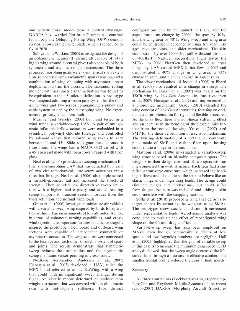
and aerostructural modes pose a control challenge.DARPA has awarded Northrop Grumman a contractfor an X-plane Obliquing Flying Wing (OFW) demon-strator, known as the Switchblade, which is scheduled tofly in 2020.Sullivan and Watkins (2003) investigated the design of
an obliquing wing aircraft (an aircraft capable of rotat-ing its wing around a central pivot) also capable of bothsymmetric and asymmetric span extensions. The threeproposed morphing goals were: symmetrical span exten-sion, roll control using asymmetric span extension, and acombination of wing obliquing with asymmetric spandeployment to trim the aircraft. The maximum rollingmoment with asymmetric span actuation was found tobe equivalent to the $5# aileron deflection. A prototypewas designed adopting a worm gear system for the obli-quing wing and two servos commanding a pulley andcable system to deploy the telescoping wing. No exper-imental prototype has been built.Marmier and Wereley (2003) built and tested in a
wind tunnel a variable-sweep UAV. A pair of antago-nistic inflatable bellow actuators were embedded in acylindrical polyvinyl chloride fuselage and controlledby solenoid valves that allowed wing sweep to varybetween 0# and 45#. Slide rods guaranteed a smoothtranslation. The wings had a NACA 0012 airfoil witha 45
00span and made with foam cores wrapped with fiber
glass.Neal et al. (2004) provided a sweeping mechanism for
their shape-morphing UAV that was actuated by meansof two electromechanical, lead-screw actuators via athree-bar linkage. Neal et al. (2006) also implementeda variable-geometry tail and increased the structuralstrength. They included new direct-drive sweep actua-tors with a higher load capacity and added rotatingsweep supports to transmit reaction torques from thetwist actuation and normal wing loads.Grant et al. (2006) investigated miniature air vehicles
with a variable-sweep wing inspired by birds for opera-tion within urban environments at low altitudes. Agility,in terms of enhanced turning capabilities, and cross-wind rejection are important features, and hence seagullsinspired the prototype. The inboard and outboard wingsections were capable of independent symmetric orasymmetric actuation. The wing sections were connectedto the fuselage and each other through a system of sparsand joints. The results demonstrate that symmetricsweep reduces the turn radius and the asymmetricsweep maintains sensor pointing in cross-winds.NextGen Aeronautics (Andersen et al., 2007;
Flanagan et al., 2007) developed a UAV, called theMFX-1 and referred to as the BatWing, with a wingthat could undergo significant sweep changes duringflight. An electric motor deformed an endoskeletonwingbox structure that was covered with an elastomericskin with out-of-plane stiffeners. Five distinct
configurations can be maintained in flight, and theaspect ratio can change by 200%, the span by 40%,and the wing area by 70%. Wing sweep and wing areacould be controlled independently using four-bar link-ages, revolute joints, and slider mechanisms. The skincould strain by over 100% but still withstand airloadsof 400 lbs/ft. NextGen successfully flight tested theMFX-1 in 2006. NextGen then developed a largermorphing UAV named MFX-2 that flew in 2007 anddemonstrated a 40% change in wing area, a 73%change in span, and a 177% change in aspect ratio.
The scissor-mechanisms of Joo et al. (2006) or Bhartiet al. (2007) also resulted in a change in sweep. Themechanism by Bharti et al. (2007) was based on theTSCh wing by NextGen Aeronautics Inc. (Andersenet al., 2007; Flanagan et al., 2007) and implemented asa pin-jointed mechanism. Grady (2010) extended thewing concept of NextGen Aeronautics, focusing on opti-mal actuator orientation for rigid and flexible structures.As the links flex, there is a non-linear stiffening effectand an increase in the bending of the flexible links fur-ther from the root of the wing. Yu et al. (2007) usedSMP for the shear deformation of a scissor-mechanism.The twisting deformation of a rectangular compositeplate made of SMP and carbon fiber upon heatingcould rotate a hinge in the mechanism.
Mattioni et al. (2006) investigated a variable-sweepwing concept based on bi-stable composite spars. Thewingbox in their design consisted of two spars with aninterconnected truss!rib structure. Each spar had a sig-nificant transverse curvature, which increased the bend-ing stiffness and also allowed the spar to behave like anelastic hinge under high drag loads. The design couldeliminate hinges and mechanisms, but could sufferfrom fatigue. No skin was included and adding a skincould interfere with the snapping motion.
Sofla et al. (2010) proposed a wing that deforms totarget shapes by actuating the wingbox using SMAs.The prototypes show excellent and smooth movementunder representative loads. Aerodynamic analysis wasconducted to evaluate the effect of reconfigured wingshape on the lift and drag coefficients.
Variable-wing sweep has also been employed onMAVs, even though compressibility effects at lowspeeds and low Reynolds numbers are negligible. Hallet al. (2005) highlighted that the goal of variable sweepin this case is to increase the minimum drag speed. CFDanalysis showed that the sweep angle decreased the lift-curve slope through a decrease in effective camber. Thesmaller frontal profile reduced the drag at high speeds.
Summary
All three contractors (Lockheed Martin, Hypercomp/NextGen and Raytheon Missile Systems) of the recent(2000!2007) DARPA Morphing Aircraft Structures
Morphing Aircraft 839
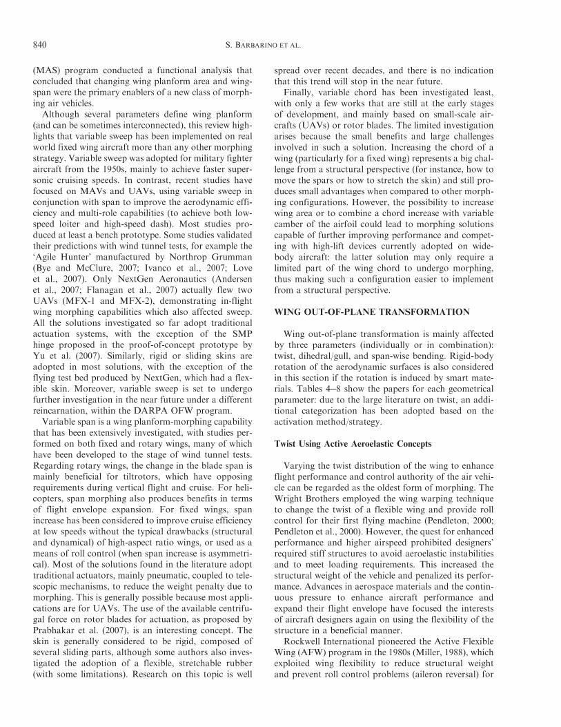
(MAS) program conducted a functional analysis thatconcluded that changing wing planform area and wing-span were the primary enablers of a new class of morph-ing air vehicles.Although several parameters define wing planform
(and can be sometimes interconnected), this review high-lights that variable sweep has been implemented on realworld fixed wing aircraft more than any other morphingstrategy. Variable sweep was adopted for military fighteraircraft from the 1950s, mainly to achieve faster super-sonic cruising speeds. In contrast, recent studies havefocused on MAVs and UAVs, using variable sweep inconjunction with span to improve the aerodynamic effi-ciency and multi-role capabilities (to achieve both low-speed loiter and high-speed dash). Most studies pro-duced at least a bench prototype. Some studies validatedtheir predictions with wind tunnel tests, for example the‘Agile Hunter’ manufactured by Northrop Grumman(Bye and McClure, 2007; Ivanco et al., 2007; Loveet al., 2007). Only NextGen Aeronautics (Andersenet al., 2007; Flanagan et al., 2007) actually flew twoUAVs (MFX-1 and MFX-2), demonstrating in-flightwing morphing capabilities which also affected sweep.All the solutions investigated so far adopt traditionalactuation systems, with the exception of the SMPhinge proposed in the proof-of-concept prototype byYu et al. (2007). Similarly, rigid or sliding skins areadopted in most solutions, with the exception of theflying test bed produced by NextGen, which had a flex-ible skin. Moreover, variable sweep is set to undergofurther investigation in the near future under a differentreincarnation, within the DARPA OFW program.Variable span is a wing planform-morphing capability
that has been extensively investigated, with studies per-formed on both fixed and rotary wings, many of whichhave been developed to the stage of wind tunnel tests.Regarding rotary wings, the change in the blade span ismainly beneficial for tiltrotors, which have opposingrequirements during vertical flight and cruise. For heli-copters, span morphing also produces benefits in termsof flight envelope expansion. For fixed wings, spanincrease has been considered to improve cruise efficiencyat low speeds without the typical drawbacks (structuraland dynamical) of high-aspect ratio wings, or used as ameans of roll control (when span increase is asymmetri-cal). Most of the solutions found in the literature adopttraditional actuators, mainly pneumatic, coupled to tele-scopic mechanisms, to reduce the weight penalty due tomorphing. This is generally possible because most appli-cations are for UAVs. The use of the available centrifu-gal force on rotor blades for actuation, as proposed byPrabhakar et al. (2007), is an interesting concept. Theskin is generally considered to be rigid, composed ofseveral sliding parts, although some authors also inves-tigated the adoption of a flexible, stretchable rubber(with some limitations). Research on this topic is well
spread over recent decades, and there is no indicationthat this trend will stop in the near future.
Finally, variable chord has been investigated least,with only a few works that are still at the early stagesof development, and mainly based on small-scale air-crafts (UAVs) or rotor blades. The limited investigationarises because the small benefits and large challengesinvolved in such a solution. Increasing the chord of awing (particularly for a fixed wing) represents a big chal-lenge from a structural perspective (for instance, how tomove the spars or how to stretch the skin) and still pro-duces small advantages when compared to other morph-ing configurations. However, the possibility to increasewing area or to combine a chord increase with variablecamber of the airfoil could lead to morphing solutionscapable of further improving performance and compet-ing with high-lift devices currently adopted on wide-body aircraft: the latter solution may only require alimited part of the wing chord to undergo morphing,thus making such a configuration easier to implementfrom a structural perspective.
WING OUT-OF-PLANE TRANSFORMATION
Wing out-of-plane transformation is mainly affectedby three parameters (individually or in combination):twist, dihedral/gull, and span-wise bending. Rigid-bodyrotation of the aerodynamic surfaces is also consideredin this section if the rotation is induced by smart mate-rials. Tables 4!8 show the papers for each geometricalparameter: due to the large literature on twist, an addi-tional categorization has been adopted based on theactivation method/strategy.
Twist Using Active Aeroelastic Concepts
Varying the twist distribution of the wing to enhanceflight performance and control authority of the air vehi-cle can be regarded as the oldest form of morphing. TheWright Brothers employed the wing warping techniqueto change the twist of a flexible wing and provide rollcontrol for their first flying machine (Pendleton, 2000;Pendleton et al., 2000). However, the quest for enhancedperformance and higher airspeed prohibited designers’required stiff structures to avoid aeroelastic instabilitiesand to meet loading requirements. This increased thestructural weight of the vehicle and penalized its perfor-mance. Advances in aerospace materials and the contin-uous pressure to enhance aircraft performance andexpand their flight envelope have focused the interestsof aircraft designers again on using the flexibility of thestructure in a beneficial manner.
Rockwell International pioneered the Active FlexibleWing (AFW) program in the 1980s (Miller, 1988), whichexploited wing flexibility to reduce structural weightand prevent roll control problems (aileron reversal) for
840 S. BARBARINO ET AL.
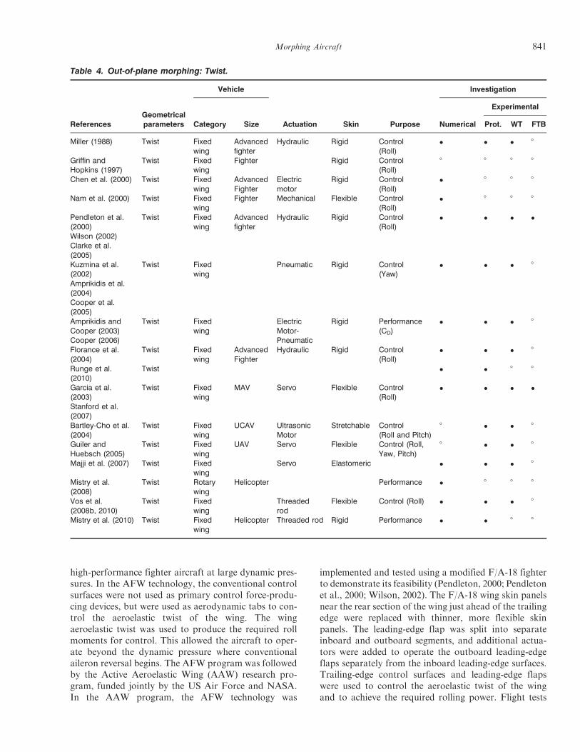
high-performance fighter aircraft at large dynamic pres-sures. In the AFW technology, the conventional controlsurfaces were not used as primary control force-produ-cing devices, but were used as aerodynamic tabs to con-trol the aeroelastic twist of the wing. The wingaeroelastic twist was used to produce the required rollmoments for control. This allowed the aircraft to oper-ate beyond the dynamic pressure where conventionalaileron reversal begins. The AFW program was followedby the Active Aeroelastic Wing (AAW) research pro-gram, funded jointly by the US Air Force and NASA.In the AAW program, the AFW technology was
implemented and tested using a modified F/A-18 fighterto demonstrate its feasibility (Pendleton, 2000; Pendletonet al., 2000; Wilson, 2002). The F/A-18 wing skin panelsnear the rear section of the wing just ahead of the trailingedge were replaced with thinner, more flexible skinpanels. The leading-edge flap was split into separateinboard and outboard segments, and additional actua-tors were added to operate the outboard leading-edgeflaps separately from the inboard leading-edge surfaces.Trailing-edge control surfaces and leading-edge flapswere used to control the aeroelastic twist of the wingand to achieve the required rolling power. Flight tests
Table 4. Out-of-plane morphing: Twist.
ReferencesGeometricalparameters
Vehicle
Actuation Skin Purpose
Investigation
Category Size Numerical
Experimental
Prot. WT FTB
Miller (1988) Twist Fixedwing
Advancedfighter
Hydraulic Rigid Control(Roll)
! ! ! 8
Griffin andHopkins (1997)
Twist Fixedwing
Fighter Rigid Control(Roll)
8 8 8 8
Chen et al. (2000) Twist Fixedwing
AdvancedFighter
Electricmotor
Rigid Control(Roll)
! 8 8 8
Nam et al. (2000) Twist Fixedwing
Fighter Mechanical Flexible Control(Roll)
! 8 8 8
Pendleton et al.(2000)Wilson (2002)Clarke et al.(2005)
Twist Fixedwing
Advancedfighter
Hydraulic Rigid Control(Roll)
! ! ! !
Kuzmina et al.(2002)Amprikidis et al.(2004)Cooper et al.(2005)
Twist Fixedwing
Pneumatic Rigid Control(Yaw)
! ! ! 8
Amprikidis andCooper (2003)Cooper (2006)
Twist Fixedwing
ElectricMotor-Pneumatic
Rigid Performance(CD)
! ! ! 8
Florance et al.(2004)
Twist Fixedwing
AdvancedFighter
Hydraulic Rigid Control(Roll)
! ! ! 8
Runge et al.(2010)
Twist ! ! 8 8
Garcia et al.(2003)Stanford et al.(2007)
Twist Fixedwing
MAV Servo Flexible Control(Roll)
! ! ! !
Bartley-Cho et al.(2004)
Twist Fixedwing
UCAV UltrasonicMotor
Stretchable Control(Roll and Pitch)
8 ! ! 8
Guiler andHuebsch (2005)
Twist Fixedwing
UAV Servo Flexible Control (Roll,Yaw, Pitch)
8 ! ! 8
Majji et al. (2007) Twist Fixedwing
Servo Elastomeric ! ! ! 8
Mistry et al.(2008)
Twist Rotarywing
Helicopter Performance ! 8 8 8
Vos et al.(2008b, 2010)
Twist Fixedwing
Threadedrod
Flexible Control (Roll) ! ! ! 8
Mistry et al. (2010) Twist Fixedwing
Helicopter Threaded rod Rigid Performance ! ! 8 8
Morphing Aircraft 841
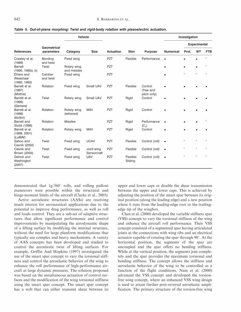
demonstrated that 1g/360# rolls, and rolling pulloutmaneuvers were possible within the structural andhinge-moment limits of the aircraft (Clarke et al., 2005).Active aeroelastic structures (AASs) are receiving
much interest for aeronautical applications due to thepotential to improve drag performance, as well as rolland loads control. They are a sub-set of adaptive struc-tures that allow significant performance and controlimprovements by manipulating the aerodynamic shapeof a lifting surface by modifying the internal structure,without the need for large planform modifications thattypically use complex and heavy mechanisms. A varietyof AAS concepts has been developed and studied tocontrol the aeroelastic twist of lifting surfaces. Forexample, Griffin And Hopkins (1997) investigated theuse of the smart spar concept to vary the torsional stiff-ness and control the aeroelastic behavior of the wing toenhance the roll performance of high-performance air-craft at large dynamic pressures. The solution proposedwas based on the simultaneous actuation of control sur-faces and the modification of the wing torsional stiffnessusing the smart spar concept. The smart spar concepthas a web that can either transmit shear between its
upper and lower caps or disable the shear transmissionbetween the upper and lower caps. This is achieved byadjusting the position of the smart spar between its orig-inal position (along the leading edge) and a new positionwhere it runs from the leading-edge root to the trailing-edge tip of the wingbox.
Chen et al. (2000) developed the variable stiffness spar(VSS) concept to vary the torsional stiffness of the wingand enhance the aircraft roll performance. Their VSSconcept consisted of a segmented spar having articulatedjoints at the connections with wing ribs and an electricalactuator capable of rotating the spar through 90#. At thehorizontal position, the segments of the spar areuncoupled and the spar offers no bending stiffness.While at the vertical position, the segments join comple-tely and the spar provides the maximum torsional andbending stiffness. The concept allows the stiffness andaeroelastic behavior of the wing to be controlled as afunction of the flight conditions. Nam et al. (2000)advanced the VSS concept and developed the torsion-free wing concept, where an enhanced VSS wing designis used to attain further post-reversal aeroelastic ampli-fication. The primary structure of the torsion-free wing
Table 5. Out-of-plane morphing: Twist and rigid-body rotation with piezoelectric actuation.
ReferencesGeometricalparameters
Vehicle
Actuation Skin Purpose
Investigation
Category Size Numerical
Experimental
Prot. WT FTB
Crawley et al.(1989)
Bendingand twist
Fixed wing PZT Flexible Performance ! ! ! 8
Barrett(1990, 1992a, b)
Twist Rotary wingand missiles
PZT ! ! ! 8
Ehlers andWeisshaar(1990, 1992)
Camberand twist
Fixed wing PZT ! 8 8 8
Barrett et al.(1997)(Mothra)
Rotation Fixed wing Small UAV PZT Flexible Control(Yaw andpitch only)
! ! ! !
Barrett et al.(1996)(Gamara)
Twist Rotary wing Small UAV PZT Rigid Control ! ! ! !
Barrett et al.(1998)(Kolibri)
Rotation Rotary wing(tethered)
MAV PZT Rigid Control ! ! ! !
Barrett andStutts (1998)
Rotation Missiles PZT Rigid Performance(CL)
! ! ! 8
Barrett et al.(1998, 2001)(LuMAV)
Rotation Rotary wing MAV PZT Rigid Control ! ! ! !
Sahoo andCesnik (2002)
Twist Fixed wing UCAV PZT Flexible Control (roll) ! 8 8 8
Cesnik andBrown (2003)
Twist Fixed wing Joint-wingSensorcraft
PZT Flexible Control (roll) ! 8 8 8
Detrick andWashington(2007)
Twist Fixed wing UAV PZT Flexible-Sliding
Control (roll) ! 8 8 8
842 S. BARBARINO ET AL.
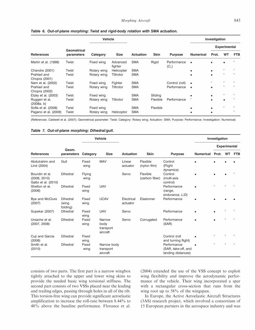
consists of two parts. The first part is a narrow wingboxtightly attached to the upper and lower wing skins toprovide the needed basic wing torsional stiffness. Thesecond part consists of two VSSs placed near the leadingand trailing edges, passing through holes in all of the rib.This torsion-free wing can provide significant aeroelasticamplification to increase the roll-rate between 8.44% to48% above the baseline performance. Florance et al.
(2004) extended the use of the VSS concept to exploitwing flexibility and improve the aerodynamic perfor-mance of the vehicle. Their wing incorporated a sparwith a rectangular cross-section that runs from thewing root up to 58% of the wingspan.
In Europe, the Active Aeroelastic Aircraft Structures(3AS) research project, which involved a consortium of15 European partners in the aerospace industry and was
Table 6. Out-of-plane morphing: Twist and rigid-body rotation with SMA actuation.
ReferencesGeometricalparameters
Vehicle
Actuation Skin Purpose
Investigation
Category Size Numerical
Experimental
Prot. WT FTB
Martin et al. (1998) Twist Fixed wing Advancedfighter
SMA Rigid Performance(CL)
! ! ! 8
Chandra (2001) Twist Rotary wing Helicopter SMA ! ! 8 8Prahlad andChopra (2001)
Twist Rotary wing Tiltrotor SMA ! ! 8 8
Nam et al. (2002) Twist Fixed wing Fighter SMA Control (roll) ! 8 8 8Prahlad andChopra (2002)
Twist Rotary wing Tiltrotor SMA Performance ! ! 8 8
Elzey et al. (2003) Twist Fixed wing SMA Sliding ! ! 8 8Ruggeri et al.(2008a, b)
Twist Rotary wing Tiltrotor SMA Flexible Performance 8 ! ! 8
Sofla et al. (2008) Twist Fixed wing SMA Flexible ! ! 8 8Pagano et al. (2009) Twist Rotary wing Helicoptor SMA ! ! 8
(References: Caldwell et al. (2007); Geometrical parameter: Twist; Category: Rotary wing; Actuation: SMA; Purpose: Performance; Investigation: Numerical)
Table 7. Out-of-plane morphing: Dihedral/gull.
ReferencesGeom.
parameters
Vehicle
Actuation Skin Purpose
Investigation
Category Size Numerical
Experimental
Prot. WT FTB
Abdulrahim andLind (2004)
Gull Fixedwing
MAV Linearactuator
Flexible(nylon film)
Control(Flightdynamics)
! ! ! !
Bourdin et al.(2008, 2010)Gatto et al. (2010)
Dihedral Flyingwing
Servo Flexible(carbon fiber)
Control(multi-axiscontrol)
! ! ! 8
Shelton et al.(2006)
Dihedral Fixedwing
UAV Performance(range,endurance, L/D)
! 8 8 8
Bye and McClure(2007)
Dihedral(wingfolding)
Fixedwing
UCAV Electricalactuator
Elastomer Performance ! ! ! !
Supekar (2007) Dihedral Fixedwing
UAV Servo Performance ! ! 8 8
Ursache et al.(2007, 2008)
Dihedral Fixedwing
Narrowbodytransportaircraft
Servo Corrugated Performance(SAR)
! ! 8 8
Cuji and Garcia(2008)
Dihedral Fixedwing
Control (rolland turning flight)
! 8 8 8
Smith et al.(2010)
Dihedral Fixedwing
Narrow bodytransportaircraft
Performance(SAR, take-off, andlanding distances)
! 8 8 8
Morphing Aircraft 843
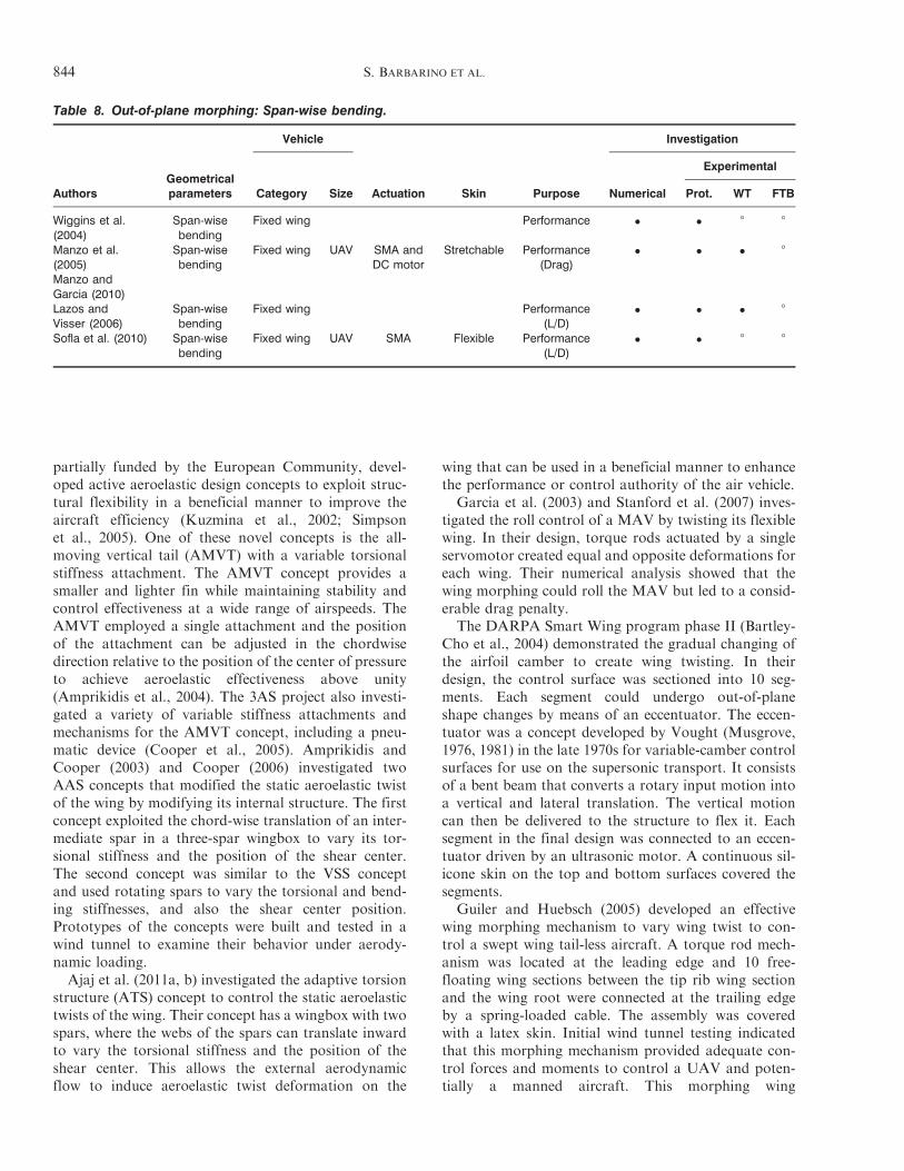
partially funded by the European Community, devel-oped active aeroelastic design concepts to exploit struc-tural flexibility in a beneficial manner to improve theaircraft efficiency (Kuzmina et al., 2002; Simpsonet al., 2005). One of these novel concepts is the all-moving vertical tail (AMVT) with a variable torsionalstiffness attachment. The AMVT concept provides asmaller and lighter fin while maintaining stability andcontrol effectiveness at a wide range of airspeeds. TheAMVT employed a single attachment and the positionof the attachment can be adjusted in the chordwisedirection relative to the position of the center of pressureto achieve aeroelastic effectiveness above unity(Amprikidis et al., 2004). The 3AS project also investi-gated a variety of variable stiffness attachments andmechanisms for the AMVT concept, including a pneu-matic device (Cooper et al., 2005). Amprikidis andCooper (2003) and Cooper (2006) investigated twoAAS concepts that modified the static aeroelastic twistof the wing by modifying its internal structure. The firstconcept exploited the chord-wise translation of an inter-mediate spar in a three-spar wingbox to vary its tor-sional stiffness and the position of the shear center.The second concept was similar to the VSS conceptand used rotating spars to vary the torsional and bend-ing stiffnesses, and also the shear center position.Prototypes of the concepts were built and tested in awind tunnel to examine their behavior under aerody-namic loading.Ajaj et al. (2011a, b) investigated the adaptive torsion
structure (ATS) concept to control the static aeroelastictwists of the wing. Their concept has a wingbox with twospars, where the webs of the spars can translate inwardto vary the torsional stiffness and the position of theshear center. This allows the external aerodynamicflow to induce aeroelastic twist deformation on the
wing that can be used in a beneficial manner to enhancethe performance or control authority of the air vehicle.
Garcia et al. (2003) and Stanford et al. (2007) inves-tigated the roll control of a MAV by twisting its flexiblewing. In their design, torque rods actuated by a singleservomotor created equal and opposite deformations foreach wing. Their numerical analysis showed that thewing morphing could roll the MAV but led to a consid-erable drag penalty.
The DARPA Smart Wing program phase II (Bartley-Cho et al., 2004) demonstrated the gradual changing ofthe airfoil camber to create wing twisting. In theirdesign, the control surface was sectioned into 10 seg-ments. Each segment could undergo out-of-planeshape changes by means of an eccentuator. The eccen-tuator was a concept developed by Vought (Musgrove,1976, 1981) in the late 1970s for variable-camber controlsurfaces for use on the supersonic transport. It consistsof a bent beam that converts a rotary input motion intoa vertical and lateral translation. The vertical motioncan then be delivered to the structure to flex it. Eachsegment in the final design was connected to an eccen-tuator driven by an ultrasonic motor. A continuous sil-icone skin on the top and bottom surfaces covered thesegments.
Guiler and Huebsch (2005) developed an effectivewing morphing mechanism to vary wing twist to con-trol a swept wing tail-less aircraft. A torque rod mech-anism was located at the leading edge and 10 free-floating wing sections between the tip rib wing sectionand the wing root were connected at the trailing edgeby a spring-loaded cable. The assembly was coveredwith a latex skin. Initial wind tunnel testing indicatedthat this morphing mechanism provided adequate con-trol forces and moments to control a UAV and poten-tially a manned aircraft. This morphing wing
Table 8. Out-of-plane morphing: Span-wise bending.
AuthorsGeometricalparameters
Vehicle
Actuation Skin Purpose
Investigation
Category Size Numerical
Experimental
Prot. WT FTB
Wiggins et al.(2004)
Span-wisebending
Fixed wing Performance ! ! 8 8
Manzo et al.(2005)Manzo andGarcia (2010)
Span-wisebending
Fixed wing UAV SMA andDC motor
Stretchable Performance(Drag)
! ! ! 8
Lazos andVisser (2006)
Span-wisebending
Fixed wing Performance(L/D)
! ! ! 8
Sofla et al. (2010) Span-wisebending
Fixed wing UAV SMA Flexible Performance(L/D)
! ! 8 8
844 S. BARBARINO ET AL.
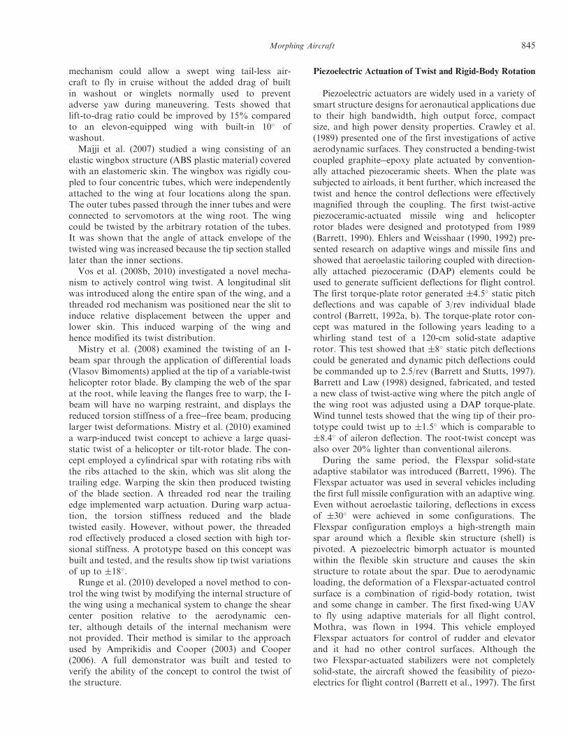
mechanism could allow a swept wing tail-less air-craft to fly in cruise without the added drag of builtin washout or winglets normally used to preventadverse yaw during maneuvering. Tests showed thatlift-to-drag ratio could be improved by 15% comparedto an elevon-equipped wing with built-in 10# ofwashout.Majji et al. (2007) studied a wing consisting of an
elastic wingbox structure (ABS plastic material) coveredwith an elastomeric skin. The wingbox was rigidly cou-pled to four concentric tubes, which were independentlyattached to the wing at four locations along the span.The outer tubes passed through the inner tubes and wereconnected to servomotors at the wing root. The wingcould be twisted by the arbitrary rotation of the tubes.It was shown that the angle of attack envelope of thetwisted wing was increased because the tip section stalledlater than the inner sections.Vos et al. (2008b, 2010) investigated a novel mecha-
nism to actively control wing twist. A longitudinal slitwas introduced along the entire span of the wing, and athreaded rod mechanism was positioned near the slit toinduce relative displacement between the upper andlower skin. This induced warping of the wing andhence modified its twist distribution.Mistry et al. (2008) examined the twisting of an I-
beam spar through the application of differential loads(Vlasov Bimoments) applied at the tip of a variable-twisthelicopter rotor blade. By clamping the web of the sparat the root, while leaving the flanges free to warp, the I-beam will have no warping restraint, and displays thereduced torsion stiffness of a free!free beam, producinglarger twist deformations. Mistry et al. (2010) examineda warp-induced twist concept to achieve a large quasi-static twist of a helicopter or tilt-rotor blade. The con-cept employed a cylindrical spar with rotating ribs withthe ribs attached to the skin, which was slit along thetrailing edge. Warping the skin then produced twistingof the blade section. A threaded rod near the trailingedge implemented warp actuation. During warp actua-tion, the torsion stiffness reduced and the bladetwisted easily. However, without power, the threadedrod effectively produced a closed section with high tor-sional stiffness. A prototype based on this concept wasbuilt and tested, and the results show tip twist variationsof up to $18#.Runge et al. (2010) developed a novel method to con-
trol the wing twist by modifying the internal structure ofthe wing using a mechanical system to change the shearcenter position relative to the aerodynamic cen-ter, although details of the internal mechanism werenot provided. Their method is similar to the approachused by Amprikidis and Cooper (2003) and Cooper(2006). A full demonstrator was built and tested toverify the ability of the concept to control the twist ofthe structure.
Piezoelectric Actuation of Twist and Rigid-Body Rotation
Piezoelectric actuators are widely used in a variety ofsmart structure designs for aeronautical applications dueto their high bandwidth, high output force, compactsize, and high power density properties. Crawley et al.(1989) presented one of the first investigations of activeaerodynamic surfaces. They constructed a bending-twistcoupled graphite!epoxy plate actuated by convention-ally attached piezoceramic sheets. When the plate wassubjected to airloads, it bent further, which increased thetwist and hence the control deflections were effectivelymagnified through the coupling. The first twist-activepiezoceramic-actuated missile wing and helicopterrotor blades were designed and prototyped from 1989(Barrett, 1990). Ehlers and Weisshaar (1990, 1992) pre-sented research on adaptive wings and missile fins andshowed that aeroelastic tailoring coupled with direction-ally attached piezoceramic (DAP) elements could beused to generate sufficient deflections for flight control.The first torque-plate rotor generated $4.5# static pitchdeflections and was capable of 3/rev individual bladecontrol (Barrett, 1992a, b). The torque-plate rotor con-cept was matured in the following years leading to awhirling stand test of a 120-cm solid-state adaptiverotor. This test showed that $8# static pitch deflectionscould be generated and dynamic pitch deflections couldbe commanded up to 2.5/rev (Barrett and Stutts, 1997).Barrett and Law (1998) designed, fabricated, and testeda new class of twist-active wing where the pitch angle ofthe wing root was adjusted using a DAP torque-plate.Wind tunnel tests showed that the wing tip of their pro-totype could twist up to $1.5# which is comparable to$8.4# of aileron deflection. The root-twist concept wasalso over 20% lighter than conventional ailerons.
During the same period, the Flexspar solid-stateadaptive stabilator was introduced (Barrett, 1996). TheFlexspar actuator was used in several vehicles includingthe first full missile configuration with an adaptive wing.Even without aeroelastic tailoring, deflections in excessof $30# were achieved in some configurations. TheFlexspar configuration employs a high-strength mainspar around which a flexible skin structure (shell) ispivoted. A piezoelectric bimorph actuator is mountedwithin the flexible skin structure and causes the skinstructure to rotate about the spar. Due to aerodynamicloading, the deformation of a Flexspar-actuated controlsurface is a combination of rigid-body rotation, twistand some change in camber. The first fixed-wing UAVto fly using adaptive materials for all flight control,Mothra, was flown in 1994. This vehicle employedFlexspar actuators for control of rudder and elevatorand it had no other control surfaces. Although thetwo Flexspar-actuated stabilizers were not completelysolid-state, the aircraft showed the feasibility of piezo-electrics for flight control (Barrett et al., 1997). The first
Morphing Aircraft 845
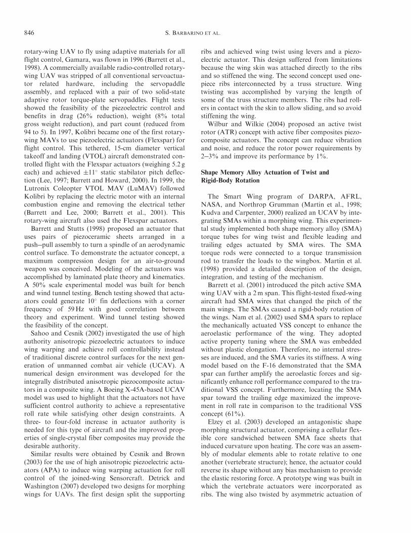
rotary-wing UAV to fly using adaptive materials for allflight control, Gamara, was flown in 1996 (Barrett et al.,1998). A commercially available radio-controlled rotary-wing UAV was stripped of all conventional servoactua-tor related hardware, including the servopaddleassembly, and replaced with a pair of two solid-stateadaptive rotor torque-plate servopaddles. Flight testsshowed the feasibility of the piezoelectric control andbenefits in drag (26% reduction), weight (8% totalgross weight reduction), and part count (reduced from94 to 5). In 1997, Kolibri became one of the first rotary-wing MAVs to use piezoelectric actuators (Flexspar) forflight control. This tethered, 15-cm diameter verticaltakeoff and landing (VTOL) aircraft demonstrated con-trolled flight with the Flexspar actuators (weighing 5.2 geach) and achieved $11# static stabilator pitch deflec-tion (Lee, 1997; Barrett and Howard, 2000). In 1999, theLutronix Coleopter VTOL MAV (LuMAV) followedKolibri by replacing the electric motor with an internalcombustion engine and removing the electrical tether(Barrett and Lee, 2000; Barrett et al., 2001). Thisrotary-wing aircraft also used the Flexspar actuators.Barrett and Stutts (1998) proposed an actuator that
uses pairs of piezoceramic sheets arranged in apush!pull assembly to turn a spindle of an aerodynamiccontrol surface. To demonstrate the actuator concept, amaximum compression design for an air-to-groundweapon was conceived. Modeling of the actuators wasaccomplished by laminated plate theory and kinematics.A 50% scale experimental model was built for benchand wind tunnel testing. Bench testing showed that actu-ators could generate 10# fin deflections with a cornerfrequency of 59Hz with good correlation betweentheory and experiment. Wind tunnel testing showedthe feasibility of the concept.Sahoo and Cesnik (2002) investigated the use of high
authority anisotropic piezoelectric actuators to inducewing warping and achieve roll controllability insteadof traditional discrete control surfaces for the next gen-eration of unmanned combat air vehicle (UCAV). Anumerical design environment was developed for theintegrally distributed anisotropic piezocomposite actua-tors in a composite wing. A Boeing X-45A-based UCAVmodel was used to highlight that the actuators not havesufficient control authority to achieve a representativeroll rate while satisfying other design constraints. Athree- to four-fold increase in actuator authority isneeded for this type of aircraft and the improved prop-erties of single-crystal fiber composites may provide thedesirable authority.Similar results were obtained by Cesnik and Brown
(2003) for the use of high anisotropic piezoelectric actu-ators (APA) to induce wing warping actuation for rollcontrol of the joined-wing Sensorcraft. Detrick andWashington (2007) developed two designs for morphingwings for UAVs. The first design split the supporting
ribs and achieved wing twist using levers and a piezo-electric actuator. This design suffered from limitationsbecause the wing skin was attached directly to the ribsand so stiffened the wing. The second concept used one-piece ribs interconnected by a truss structure. Wingtwisting was accomplished by varying the length ofsome of the truss structure members. The ribs had roll-ers in contact with the skin to allow sliding, and so avoidstiffening the wing.
Wilbur and Wilkie (2004) proposed an active twistrotor (ATR) concept with active fiber composites piezo-composite actuators. The concept can reduce vibrationand noise, and reduce the rotor power requirements by2!3% and improve its performance by 1%.
Shape Memory Alloy Actuation of Twist andRigid-Body Rotation
The Smart Wing program of DARPA, AFRL,NASA, and Northrop Grumman (Martin et al., 1998;Kudva and Carpenter, 2000) realized an UCAV by inte-grating SMAs within a morphing wing. This experimen-tal study implemented both shape memory alloy (SMA)torque tubes for wing twist and flexible leading andtrailing edges actuated by SMA wires. The SMAtorque rods were connected to a torque transmissionrod to transfer the loads to the wingbox. Martin et al.(1998) provided a detailed description of the design,integration, and testing of the mechanism.
Barrett et al. (2001) introduced the pitch active SMAwing UAV with a 2m span. This flight-tested fixed-wingaircraft had SMA wires that changed the pitch of themain wings. The SMAs caused a rigid-body rotation ofthe wings. Nam et al. (2002) used SMA spars to replacethe mechanically actuated VSS concept to enhance theaeroelastic performance of the wing. They adoptedactive property tuning where the SMA was embeddedwithout plastic elongation. Therefore, no internal stres-ses are induced, and the SMA varies its stiffness. A wingmodel based on the F-16 demonstrated that the SMAspar can further amplify the aeroelastic forces and sig-nificantly enhance roll performance compared to the tra-ditional VSS concept. Furthermore, locating the SMAspar toward the trailing edge maximized the improve-ment in roll rate in comparison to the traditional VSSconcept (61%).
Elzey et al. (2003) developed an antagonistic shapemorphing structural actuator, comprising a cellular flex-ible core sandwiched between SMA face sheets thatinduced curvature upon heating. The core was an assem-bly of modular elements able to rotate relative to oneanother (vertebrate structure); hence, the actuator couldreverse its shape without any bias mechanism to providethe elastic restoring force. A prototype wing was built inwhich the vertebrate actuators were incorporated asribs. The wing also twisted by asymmetric actuation of
846 S. BARBARINO ET AL.
its two SMA-actuated vertebrate beams. Similarly, Soflaet al. (2008) used antagonistic flexural cells to createtwo-way SMA flexural actuators using a one-wayshape memory effect. The cells provided four distinctpositions for each segment of the actuator, and two ofthe positions required no external energy to be main-tained. These actuators could control the twist of wingsections if they are incorporated as ribs and are actuatedasymmetrically.Lv et al. (2009) developed an SMA torsion actuator
based on NiTi wires and a thin-walled tube for an adap-tive wing demonstration system. The angle of attack ofthe wing could be changed continuously up to 15# in 1 s.A novel smart wing rib with the swing angles up to $10#
was investigated.SMAs have also been applied for wing twist on heli-
copter rotor blades. Prahlad and Chopra (2001) devel-oped and tested a torsional SMA actuator to alter thetwist distribution for a tiltrotor blade between hover andforward flight. The design of the actuator (torque tube)was optimized as a function of heat transfer, tempera-ture, and actuation recovery torque. The effect of heattreatment on the tuning of the actuation characteristicsof the SMA tube was also investigated, and thermoelec-tric modules were used to release excess heat through theblade surface to improve the cooling and reduce theactuation time. Chandra (2001) developed a method toinduce twisting deformation in a solid-section compositebeam using SMA bender elements. Bending!torsioncoupled graphite!epoxy composite beams with Tefloninserts were built using an autoclave molding techniqueand the Teflon inserts were replaced by SMA benderelements. The composite beams were actuated by heat-ing the SMA via electrical resistive heating, and thebending and twisting deformation measured using alaser system. Such beams with SMA elements can beused as spars in rotor blades to induce twist.The goal of the reconfigurable rotor blade program
funded by NAVAIR was to demonstrate the potential toimprove rotorcraft performance by optimizing the con-figuration of major structures in flight (Bushnell et al.,2008; Ruggeri et al., 2008b). The SMA actuation systememployed 55-Nitinol (Ni-55Ti) rotary actuators inte-grated as structural elements in a quarter-scale rotorblade to control twist. A passive torque tube transmittedthe torque from the actuator assembly near the bladeroot to the tip of blade causing the blade to twist. Alightweight spring mechanism, the Strain EnergyShuttle, provided an energy storage element betweenthe SMA actuator and the passive torque tube, andhalved the actuator system weight (Calkins et al.,2008). The actuator was tested in 2007 using a ! scalethree-blade hub assembly mounted on the BoeingAdvanced Rotor Test Stand. The wind tunnel test wasa high-fidelity assessment of the SMA actuator (Ruggeriet al., 2008a) and represents one of the first attempts to
produce a high-torque SMA actuator for the rotor envi-ronment. The actuator provided approximately 250twist transitions during 75 h of testing with no loss ofperformance or operational anomalies.
Pagano et al. (2009), within the European‘Friendcopter’ project, investigated the control of arotor blade twist using an SMA-based device to extendthe flight envelope of the helicopter. An SMA rod waspre-twisted to achieve a martensitic phase and then inte-grated in the span-wise direction within the blade struc-ture at different positions. When heated, the SMAactuator transmitted a torque couple which inducedtwist into the blade. A prototype was been built andtested, and achieved a maximum angular rotation of6#, with a corresponding transmitted moment of21.6Nm.
Dihedral/Gull
Recently variable dihedral/gull wings have arousedmuch interest because of their ability to enhance aircraftperformance and flight control. A variable dihedral wingcan: control the aerodynamic span; replace conventionalcontrol surfaces; enhance the agility and flight charac-teristics of high-performance aircraft; reduce theinduced drag (by changing the vorticity distribution);and improve the stall characteristics.
The IS-1 fighter, designed by Nikitin-Shevchenko in1932, was one of the first applications of variable dihe-dral wings, and was capable of out-of-plane morphingfrom a bi-plane to a monoplane to operate at high speed.The XB-70 supersonic bomber also used a form of three-dimensional wing morphing. This design used outerwing panel rotation to control the lift-to-drag ratio atboth low subsonic and supersonic speeds.
Abdulrahim and Lind (2004) studied the flightdynamics and characteristics of a variable gull-wingmorphing MAV. They used a hinged spar structure tosplit the wing into inboard and outboard partitions andvary the dihedral angle of each partition. A verticallinear actuator controlled the angle of the inboard sparvia a telescoping shaft to prevent binding. The angle ofthe outboard spar was passively controlled via amechanical linkage connected to the fuselage. Duringactuation, the linkage caused the inboard and outboardsections to deflect in opposite directions.
Shelton et al. (2006) studied the benefits of active mul-tiple winglets for a UAV. The use of actively controlledwinglets can enhance the low-speed performance andmaneuverability of the vehicle and can increase therange and endurance of the vehicle by up to 40%.
As part of the MAS program, Lockheed Martindeveloped the folding wing (Z-wing), where the spanlength, aspect ratio, and effective sweep angle may bevaried (Skillen and Crossley, 2008a). The folding wingdesign incorporates hinged joints at two span-wise
Morphing Aircraft 847
stations enabling rigid body motion of four primary wingsections. Two approaches to fold the wing were investi-gated: a thermo-polymer actuator driving a helical splinegear or electro-mechanical rotary actuators. However,the helical spline approach was high risk and hence elec-trical actuators were used (Bye and McClure, 2007).Elastomeric skins covered the entire wing and providedsmooth shape changes. A morphing UAV aircraft wassuccessfully flight tested.Bourdin et al. (2008) and Gatto et al. (2010) investi-
gated the use of variable-cant angle winglets for morph-ing aircraft control. A pair of winglets with adaptivecant angle were mounted at the tips of a flying wingand actuated independently. A prototype of the conceptwas constructed with servo-driven winglets at the tips ofa trapezoidal planar wing. A single pair of adaptivewinglets cannot replace all the conventional control sur-faces and an elevator was included to trim the aircraft,especially during level turns at arbitrary bank angles.The concept was modified by adding a second pair offolding wingtips (Bourdin et al., 2007, 2010), where thesplit wingtips are actuated independently. The concept ismore effective at moderate and high lift coefficients, andhence could be applied to low-speed morphing aircrafts.Cuji andGarcia (2008) studied the dynamics of aircraft
turning for symmetric and asymmetric V-shaped chang-ing wings. Wings with asymmetric dihedral performbetter in terms of bank angle, load factor, and rollingmoment coefficient than wings with symmetric dihedral.Moreover, asymmetric dihedral can enhance the turningperformance significantly without losing the ability toroll the vehicle. Very large dihedral angles are also goodfor flight missions where the bank angle is more impor-tant than the turning rate and radius.Ursache et al. (2007) investigated the MORPHing
wingLET (MORPHLET) concept to enhance the flightperformance of narrow body aircraft. The wingletsystem consisted of four partitions at the outboardregion of the wing. The cant, twist, and span of eachpartition were adjusted to maximize the vehicle perfor-mance across the entire flight envelope. Low-fidelitymulitdisciplinary design optimization (MDO) studieswere performed using the winglet system to maximizethe specific air range (SAR) at three different points ofthe flight envelope: start of initial cruise, start of finalcruise, and end of descent. Preliminary results indicatedthat a significant increase in SAR can be achieved. Amechanical prototype of the MORPHLET concept wasdesigned, built, and tested (Ursache et al., 2008). A cor-rugated skin was incorporated to allow the relative dis-placement of the MORPHLET partitions. Smith et al.(2010) formulated a constrained multi-objective MDOanalysis of the MORPHLET concept to quantify oper-ational performance benefits, and showed that a 4!5%improvement in SAR over that for fixed winglets may beachieved.
Span-wise Bending
Another way to achieve a continuous out-of-planewing morphing is through the biologically inspiredhyper elliptic cambered span (HECS) concept, devel-oped by NASA researchers. Manzo et al. (2005) inves-tigated two approaches to allow shape morphing of afurled HECS wing. The first approach employeda tendon-based spool system that was actuated using aDC motor, while the second approach used an SMAsystem. Manzo and Garcia (2010) studied the aerody-namic benefits of a furled and a planar (rigid) HECSwings, in contrast to an elliptical rigid wing. A wingwas constructed that could mimic a furled HECS profileby splitting the wing into five segments across the span.The shape morphing of the HECS wing was achievedusing SMA-actuated segments that were powered intandem using closed-loop feedback control. Wigginset al. (2004) investigated the feasibility of a single-degree-of-freedom mechanism to continuously morpha flat wing to a non-planar shape. Their scissor-likemechanism used a repeating quaternary!binary linkconfiguration to translate the motion of one wing seg-ment to the next. The mechanism was synthesized suchthat only one actuator displacement to the first linkagewas required to deform all the segments.
Sofla et al. (2010) developed a morphing wing conceptwhere the wing can flex laterally in a continuous fashionand is similar to the HECS wing concept. A prototype,made from carbon!epoxy and actuated using SMAs,was built to examine the performance of the actuators.The prototype showed excellent and smooth movementunder applied representative loads. A three-dimensional,parametric aerodynamic analysis was also conducted toevaluate the effect of the reconfigured wing shape on thelift and drag coefficients. The power consumption of atypical UAV was estimated from the aerodynamic per-formance of the wing. The numerical results showedconsiderable benefits of the wing morphing concept.
Supekar (2007) designed a morphing wing conceptwith adjustable span and gull angles. The gull anglewas controlled using a servomotor and bell-crankarrangement, whereas the outer wing allowed anincrease in span.
Summary
Out-of-plane morphing is probably the least commontype of morphing solution, perhaps with the exceptionof wing twist. Twist is the oldest shape morphing, butwas discarded for almost 80 years to prevent aeroelasticproblems. Advances in aerospace materials (composites)have made twist morphing possible, for example withthe AFW research program. Following the AFW pro-gram, large numbers of research projects across theworld have investigated methods and techniques to
848 S. BARBARINO ET AL.
achieve twist morphing. The main reason for this largeinterest is that twist morphing can produce a significantimpact on the aerodynamic behavior of a lifting surfacewithout the need for large platform modifications, suchthose associated with variable sweep or span that usuallyrequire complex and heavy mechanisms. In addition,twist morphing (similar to camber morphing) can servemultiple tasks simultaneously, such as alleviate gust andmaneuver load; increase the lift coefficient; and replaceconventional control surfaces. Furthermore, variousactuation methods ranging from SMA, piezoelectric,AAS, and others have been investigated for twistmorphing. However the state-of-art piezoelectric actua-tors still fail to deliver the actuation authority requiredto provide adequate roll control for fixed-wing air vehi-cles. Most of the research has been focused so far onactively tailoring the wing elasticity to achieve desiredtwist; moreover, traditional actuation systems have beenadopted in most of the studies which reached the windtunnel test stage.Fewer studies have focused on dihedral/gull or span-
wise bending morphing, although some have reached anadvanced stage, even producing a successful flying testbed. The interest in these morphing capabilities mainlyarose from the need to optimize the performance offixed winglets. A variety of studies and research projectsfocused on variable-cant winglets to maximize the per-formance of the air vehicle or to replace conventionalcontrol surfaces. Actuators considered in these worksare generally traditional. The most recent studies havefocused on continuous geometric morphing of the wing(root to tip) to generate improved outcomes; however,this requires complex and heavy mechanisms coupledwith flexible skins.
AIRFOIL ADJUSTMENT
Airfoil adjustment is mainly concerned with cambervariation, although there is also some research con-cerned with thickness change. Tables 9!11 summarizethe literature available, with an additional categoriza-tion using the adopted activation method/strategy. Inaerodynamics, camber represents the effective curvature(or shape) of an airfoil. The term camber control simplyrefers to the change of the curvature of the airfoil bymeans of actuators. There are many methods that can beimplemented in order to effectively vary the camber. Thewing camber can change either on specific parts (leadingor trailing edge) or in a global manner, letting the entirewing act as a unique control surface. The choice of actu-ators can be conventional (i.e., electromagnetic motors,hydraulic, pneumatic, and actuators with ‘moving’parts) or solid-state ‘smart’ materials (i.e., piezoelectrics,SMAs, rubber muscle actuators (RMAs), magnetostric-tive materials, etc.). The actuation (whether it is induced
by conventional or smart material systems) can be dis-tributed or localized.
In this section, the main focus is applications ofcamber control in fixed-wing and rotary aircraft in thesubsonic regime. The section is separated into four mainparts. The first part is organized from a flight regimestandpoint; therefore, examples of patents, flappingwing aircraft, wind mills, etc. (in addition to fixedwing and rotary aircraft) are given to better explainthe motivation and the necessity of camber morphing.The second part deals specifically with fixed-wing androtary aircraft in the subsonic regime and actuated withconventional systems. The third part deals with fixed-wing and rotary aircraft (also in the subsonic regime)that are actuated with SMAs or similar ‘muscle-like’devices. In the final, fourth part, piezoelectric actuatorsare considered.
Camber ! Motivation for Adoption on Fixed Wings
Although the idea of changing the wing camber wasborn with the first airplanes, it is far from simple-to-design devices capable of achieving the necessary defor-mation and suitable control systems. Many patents havebeen obtained and research carried out in this regard.The need for wing curvature change arises from the pos-sibility, in the subsonic regime, to adjust continuouslythe airfoil geometry at different flight conditions, thusincreasing the lift/drag ratio (Spillman, 1992). The morepossible intermediate configurations, the greater are theaerodynamic benefits. Some applications also realized asmall curvature change on the wing upper surface toincrease the aircraft performance in the transonicregime (Stanewsky, 2001).
Parker (1920) patented one of the first examples of avariable-camber wing. This concept involved changingthe wing configuration through aerodynamic loads onthe wing. This scheme divided the wing into three sec-tions using two wing spars, one at the leading edge andthe other at the two-third chord. The portion of the wingbetween the spars was flexible and the portion aft of thesecond spar rigid. The wind tunnel test results showedthat the wing had a maximum lift coefficient of 0.76 andminimum drag of 0.007.
Sachs and Mehlhorn (1991, 1993) presented a methodfor endurance maximization, which consisted of theperiodic optimal control of camber in a coordinatedprocess with a corresponding control of throttle and ele-vator. It was shown that using camber control providesan efficient means to improve the L/D ratio at eachflight condition during the unsteady phases of periodicoptimal endurance cruise. Fuel consumption during theidle phase is also minimized.
McGowan et al. (1999, 2008) outlined the morphingwing research activities at NASA Langley and also pre-sented wing concepts that allowed shape changes
Morphing Aircraft 849
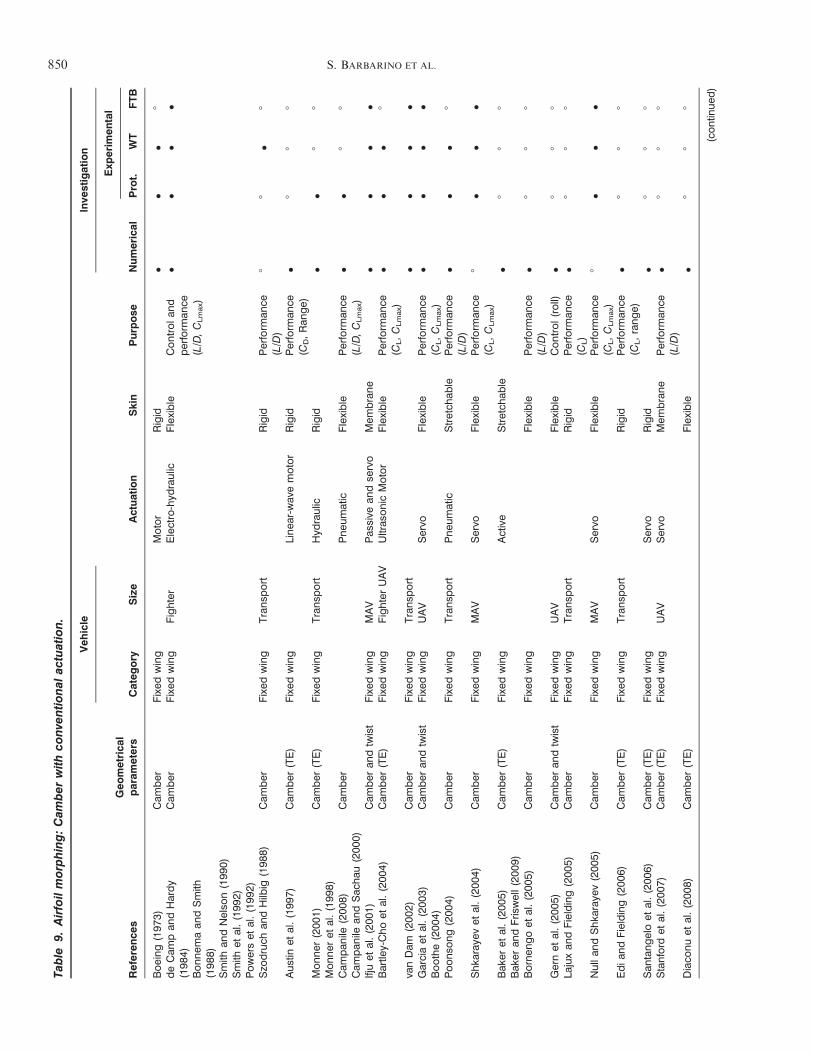
Table
9.Airfoilmorphing:Cam
berwithconve
ntional
actuation.
Reference
sGeometrical
param
eters
Vehicle
Actuation
Skin
Purpose
Inve
stigation
Category
Size
Numerica
l
Exp
erimental
Prot.
WT
FTB
Boeing(197
3)Cam
ber
Fixed
wing
Motor
Rigid
!!
!8
deCam
pan
dHardy
(198
4)Bonnem
aan
dSmith
(198
8)Smith
andNelso
n(199
0)Smith
etal.(199
2)Powerset
al.(199
2)
Cam
ber
Fixed
wing
Fighter
Electro-hyd
raulic
Flexible
Controlan
dperform
ance
(L/D,CLmax)
!!
!!
Szo
druch
andHilb
ig(198
8)Cam
ber
Fixed
wing
Transp
ort
Rigid
Perform
ance
(L/D
)8
8!
8
Austin
etal.(199
7)Cam
ber
(TE)
Fixed
wing
Linea
r-wav
emotor
Rigid
Perform
ance
(CD,Ran
ge)
!8
88
Monner
(200
1)Monner
etal.(199
8)Cam
ber
(TE)
Fixed
wing
Transp
ort
Hyd
raulic
Rigid
!!
88
Cam
pan
ile(200
8)Cam
pan
ilean
dSac
hau
(200
0)Cam
ber
Pneu
matic
Flexible
Perform
ance
(L/D,CLmax)
!!
88
Ifjuet
al.(200
1)Cam
ber
andtw
ist
Fixed
wing
MAV
Pas
sive
andse
rvo
Mem
brane
!!
!!
Bartle
y-Choet
al.(200
4)Cam
ber
(TE)
Fixed
wing
FighterUAV
Ultras
onic
Motor
Flexible
Perform
ance
(CL,CLmax)
!!
!8
vanDam
(200
2)Cam
ber
Fixed
wing
Transp
ort
!!
!!
Garciaet
al.(200
3)Boothe(200
4)Cam
ber
andtw
ist
Fixed
wing
UAV
Servo
Flexible
Perform
ance
(CL,CLmax)
!!
!!
Poonso
ng(200
4)Cam
ber
Fixed
wing
Transp
ort
Pneu
matic
Stretch
able
Perform
ance
(L/D
)!
!!
8
Shka
raye
vet
al.(200
4)Cam
ber
Fixed
wing
MAV
Servo
Flexible
Perform
ance
(CL,CLmax)
8!
!!
Bak
eret
al.(200
5)Bak
eran
dFris
well(200
9)Cam
ber
(TE)
Fixed
wing
Active
Stretch
able
!8
88
Bornen
goet
al.(200
5)Cam
ber
Fixed
wing
Flexible
Perform
ance
(L/D
)!
88
8
Gernet
al.(200
5)Cam
ber
andtw
ist
Fixed
wing
UAV
Flexible
Control(roll)
!8
88
Lajuxan
dFielding(200
5)Cam
ber
Fixed
wing
Transp
ort
Rigid
Perform
ance
(CL)
!8
88
Nullan
dShka
raye
v(200
5)Cam
ber
Fixed
wing
MAV
Servo
Flexible
Perform
ance
(CL,CLmax)
8!
!!
Edia
ndFielding(200
6)Cam
ber
(TE)
Fixed
wing
Transp
ort
Rigid
Perform
ance
(CL,range)
!8
88
San
tangeloet
al.(200
6)Cam
ber
(TE)
Fixed
wing
Servo
Rigid
!8
88
Stanford
etal.(200
7)Cam
ber
(TE)
Fixed
wing
UAV
Servo
Mem
brane
Perform
ance
(L/D
)!
88
8
Diaco
nuet
al.(200
8)Cam
ber
(TE)
Flexible
!8
88
(contin
ued
)
850 S. BARBARINO ET AL.
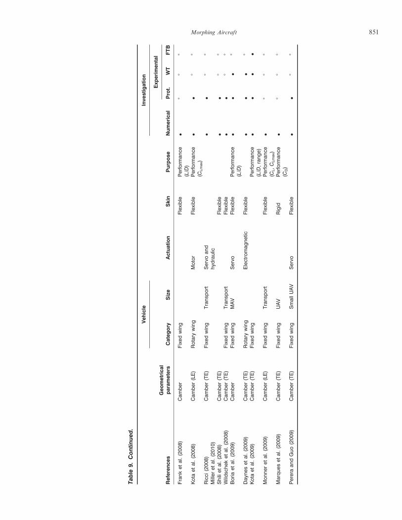
Table
9.Continued.
Reference
sGeometrical
param
eters
Vehicle
Actuation
Skin
Purpose
Inve
stigation
Category
Size
Numerica
l
Exp
erimental
Prot.
WT
FTB
Franket
al.(200
8)Cam
ber
Fixed
wing
Flexible
Perform
ance
(L/D
)!
88
8
Kota
etal.(200
8)Cam
ber
(LE)
Rotary
wing
Motor
Flexible
Perform
ance
(CLmax)
!!
88
Ricci
(200
8)Miller
etal.(201
0)Cam
ber
(TE)
Fixed
wing
Transp
ort
Servo
and
hyd
raulic
!!
88
Shili
etal.(200
8)Cam
ber
(TE)
Flexible
!!
88
Wild
schek
etal.(200
8)Cam
ber
(TE)
Fixed
wing
Transp
ort
Flexible
!!
88
Boria
etal.(200
9)Cam
ber
Fixed
wing
MAV
Servo
Flexible
Perform
ance
(L/D
)!
!!
8
Day
nes
etal.(200
9)Cam
ber
(TE)
Rotary
wing
Electromag
netic
Flexible
!!
!8
Kota
etal.(200
9)Cam
ber
(TE)
Fixed
wing
Perform
ance
(L/D
,range)
!!
!!
Monner
etal.(200
9)Cam
ber
(LE)
Fixed
wing
Transp
ort
Flexible
Perform
ance
(CL,CLmax)
!8
88
Marques
etal.(200
9)Cam
ber
(TE)
Fixed
wing
UAV
Rigid
Perform
ance
(CD)
!8
88
Pereraan
dGuo(200
9)Cam
ber
(TE)
Fixed
wing
SmallUAV
Servo
Flexible
!!
88
Morphing Aircraft 851
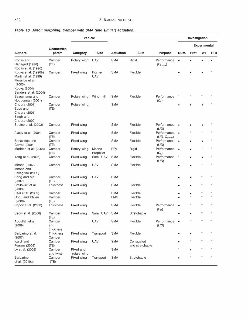
Table 10. Airfoil morphing: Camber with SMA (and similar) actuation.
AuthorsGeometrical
param.
Vehicle
Actuation Skin Purpose
Investigation
Category Size Num.
Experimental
Prot. WT FTB
Roglin andHanagud (1996)Roglin et al. (1996)
Camber(TE)
Rotary wing UAV SMA Rigid Performance(CLmax)
! ! ! !
Kudva et al. (1996b)Martin et al. (1999)Florance et al.(2003)Kudva (2004)Sanders et al. (2004)
Camber Fixed wing FighterUAV
SMA Flexible ! ! ! 8
Beauchamp andNedderman (2001)
Camber Rotary wing Wind mill SMA Flexible Performance(CL)
8 8 8 8
Chopra (2001)Epps andChopra (2001)Singh andChopra (2002)
Camber(TE)
Rotary wing SMA ! ! ! 8
Strelec et al. (2003) Camber Fixed wing SMA Flexible Performance(L/D)
! ! ! 8
Alasty et al. (2004) Camber(TE)
Fixed wing SMA Flexible Performance(L/D, CLmax)
! 8 8 8
Benavides andCorrea (2004)
Camber(TE)
Fixed wing SMA Flexible Performance(L/D)
! ! ! 8
Madden et al. (2004) Camber(TE)
Rotary wing MarinePropeller
PPy Rigid Performance(CL)
! ! 8 8
Yang et al. (2006) Camber Fixed wing Small UAV SMA Flexible Performance(L/D)
8 ! ! 8
Mirone (2007)Mirone andPellegrino (2009)
Camber Fixed wing UAV SMA Flexible ! ! 8 8
Song and Ma(2007)
Camber(TE)
Fixed wing UAV SMA ! ! 8 8
Brailovski et al.(2008)
Thickness Fixed wing SMA Flexible ! ! 8 8
Peel et al. (2009) Camber Fixed wing RMA Flexible ! ! 8 8Chou and Philen(2008)
Camber(TE)
FMC Flexible ! 8 8 8
Popov et al. (2008) Thickness Fixed wing SMA Flexible Performance(CD)
! 8 8 8
Seow et al. (2008) Camber(TE)
Fixed wing Small UAV SMA Stretchable ! ! 8 8
Abdullah et al.(2009)
Camberandthickness
UAV SMA Flexible Performance(L/D)
! 8 8 8
Barbarino et al.(2007)
ThicknessCamber
Fixed wing Transport SMA Flexible ! ! 8 8
Icardi andFerraro (2009)
Camber(TE)
Fixed wing UAV SMA Corrugatedand stretchable
! 8 8 8
Lv et al. (2009) Camberand twist
Fixed androtary wing
SMA 8 ! 8 8
Barbarinoet al. (2010a)
Camber(TE)
Fixed wing Transport SMA Stretchable ! 8 8 8
852 S. BARBARINO ET AL.
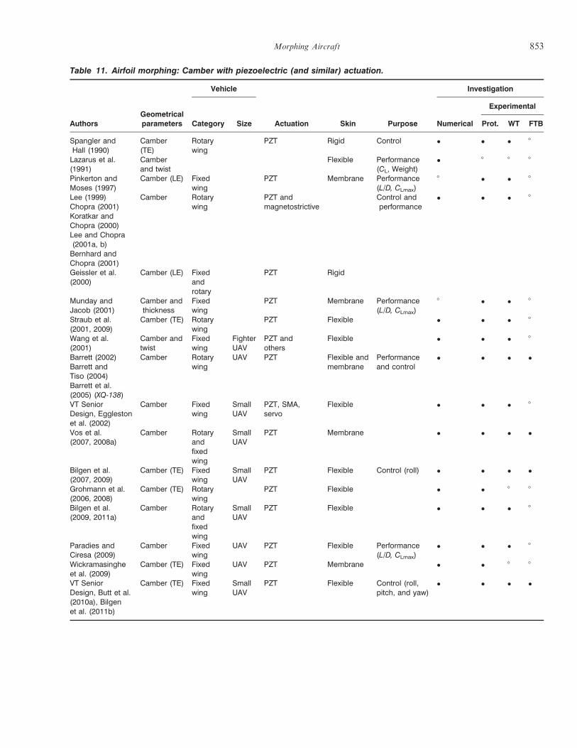
Table 11. Airfoil morphing: Camber with piezoelectric (and similar) actuation.
AuthorsGeometricalparameters
Vehicle
Actuation Skin Purpose
Investigation
Category Size Numerical
Experimental
Prot. WT FTB
Spangler andHall (1990)
Camber(TE)
Rotarywing
PZT Rigid Control ! ! ! 8
Lazarus et al.(1991)
Camberand twist
Flexible Performance(CL, Weight)
! 8 8 8
Pinkerton andMoses (1997)
Camber (LE) Fixedwing
PZT Membrane Performance(L/D, CLmax)
8 ! ! 8
Lee (1999)Chopra (2001)Koratkar andChopra (2000)Lee and Chopra(2001a, b)Bernhard andChopra (2001)
Camber Rotarywing
PZT andmagnetostrictive
Control andperformance
! ! ! 8
Geissler et al.(2000)
Camber (LE) Fixedandrotary
PZT Rigid
Munday andJacob (2001)
Camber andthickness
Fixedwing
PZT Membrane Performance(L/D, CLmax)
8 ! ! 8
Straub et al.(2001, 2009)
Camber (TE) Rotarywing
PZT Flexible ! ! ! 8
Wang et al.(2001)
Camber andtwist
Fixedwing
FighterUAV
PZT andothers
Flexible ! ! ! 8
Barrett (2002)Barrett andTiso (2004)Barrett et al.(2005) (XQ-138)
Camber Rotarywing
UAV PZT Flexible andmembrane
Performanceand control
! ! ! !
VT SeniorDesign, Egglestonet al. (2002)
Camber Fixedwing
SmallUAV
PZT, SMA,servo
Flexible ! ! ! 8
Vos et al.(2007, 2008a)
Camber Rotaryandfixedwing
SmallUAV
PZT Membrane ! ! ! !
Bilgen et al.(2007, 2009)
Camber (TE) Fixedwing
SmallUAV
PZT Flexible Control (roll) ! ! ! !
Grohmann et al.(2006, 2008)
Camber (TE) Rotarywing
PZT Flexible ! ! 8 8
Bilgen et al.(2009, 2011a)
Camber Rotaryandfixedwing
SmallUAV
PZT Flexible ! ! ! 8
Paradies andCiresa (2009)
Camber Fixedwing
UAV PZT Flexible Performance(L/D, CLmax)
! ! ! 8
Wickramasingheet al. (2009)
Camber (TE) Fixedwing
UAV PZT Membrane ! ! 8 8
VT SeniorDesign, Butt et al.(2010a), Bilgenet al. (2011b)
Camber (TE) Fixedwing
SmallUAV
PZT Flexible Control (roll,pitch, and yaw)
! ! ! !
Morphing Aircraft 853
without surface discontinuities. In one concept, referredto as the fish bone concept, the main load-bearing com-ponent resembles the spinal cord of a fish covered withan elastomeric material to transfer pressure loads to themain structure. The trailing-edge ribs can deflect up to$20# in camber and $25# in the span-wise direction.Likewise, the leading-edge ribs can deflect $25# incamber and $20# in the span-wise direction. The con-figuration was built for the assessment and demonstra-tion of the structural concept and not for wind tunneltesting. Bolonkin and Gilyard (1999) calculated the ben-efits of variable-camber ailerons that span the majorityof the wing. The main purpose is maximizing the L/Dratio and reducing the fuel consumption of subsonictransport aircraft.Recent attention is given to multi-objective and multi-
level (or multiscale) optimization problems due to theincreasing computational power. The design of morph-ing aircraft (or airfoil) geometries is now commonlyposed as a multilevel, multi-objective optimization prob-lem. In most morphing aircraft problems, the two com-peting objectives are (1) maneuverability and (2) longrange/endurance. In general, multi-objective problemshave many optimal solutions each depicting a differentcompromise scenario. Each optimal solution is knownas a Pareto point, and the set of all these points repre-sents the Pareto curve. The Pareto description is knownto be a powerful means of showing the global picture ofthe solution field.Prock et al. (2002) explored a process to link analyt-
ical models and optimization tools to create energy-effi-cient, lightweight wing/structure/actuator combinationsfor morphing aircraft wings. The energy required todeform the airfoil was used as the performance indexfor optimization while the aerodynamic performancesuch as lift or drag was constrained. Three different,but related, topics were considered: energy required tooperate articulated trailing-edge flaps and slats attachedto flexible two-dimensional (2D) airfoils; optimal, min-imum energy, articulated control deflections on wings togenerate lift; and, deformable airfoils with cross-sec-tional shape changes requiring strain energy changes tomove from one lift coefficient to another. Results indi-cate that a formal optimization scheme using minimumactuator energy as an objective and internal structuraltopology features as design variables can identify thebest actuators and their most effective locations sothat minimal energy is required to operate a morphingwing. Gano and Renaud (2002) presented a concept toincrease the efficiency of a UAV, based on changing theairfoil thickness. They suggested to decrease the volumeof the wing tanks as the fuel is depleted, thus inducing athickness reduction and thereby a drag reduction. Ganoet al. (2004) discussed solution strategies for multi-objec-tive, multi-level morphing aircraft design problems. Twodesign tools were explored to combat the issues in the
optimization problem: conversion to a single-leveldesign problem and the use of variable-fidelity optimi-zation. A variable-fidelity optimization framework wasdiscussed and applied to design a buckle wing morphingaircraft concept. The buckle wing in cruise conditionslooks like a typical UAV with a standard high-aspectratio wing; though the wing may be slightly thicker.However, the wing is actually composed of two thinnerwings which are fused together to form this high-aspectratio wing, and when the need for maneuverability arisesthe aircraft can, via a buckling load applied at the wingtips, morph into a configuration that resembles abiplane with its outboard wing tips joined together.When the UAV is in the buckled state, it can generatemuch more lift and becomes more agile. The aerody-namic models used in the study include a high-fidelityCFD model and a low-fidelity panel method. Rusnellet al. (2004) also investigated the buckle-wing concept.Compromise Programming was used as the optimizationmethod and the Vortex-Panel Method was used to cal-culate the aerodynamic behavior. The buckle-wingUAV’s enhanced capabilities were demonstrated bothquantitatively and qualitatively. Johnston at al. (2003,2007) analyzed the ‘resistance’ of an airfoil to change itsshape due to elastic and aerodynamic forces. The workrequired to overcome this force was examined in a vari-ety of different conditions. The energies required for apitching flat plate, conventional flap, conformal flap,and two variable-camber configurations were investi-gated. It was determined that the distribution and thesize of actuators can make a significant difference in theenergy required. Namgoong et al. (2006) presentedthe strain energy required to change the shape (camberand thickness distribution) of a wing section. The addi-tional power input to the morphing section was taken asa new design constraint. This research determined theenergy required to deform airfoil sections, and proposedthat the morphing airfoil design problem is multi-objec-tive when the aerodynamic constraints and strain energyproblems are both solved. Zhao et al. (2009) presented arobust airfoil design problem. The authors reported thatthe performance of an initial airfoil is enhanced throughreducing the standard deviation of CLmax. They alsoconcluded that the maximum thickness has the domi-nant effect on the mean value of CLmax, the location ofmaximum thickness has the dominant effect on the stan-dard deviation of CLmax, and the maximum camber hasa little effect on both the mean value and the standarddeviation.
Camber ! Motivation for Adoption in Rotary Wings
In addition to the fixed-wing applications above,rotary aircraft have been an active research area withthe introduction of piezoelectric materials for vibrationcontrol. Although the references presented next do not
854 S. BARBARINO ET AL.
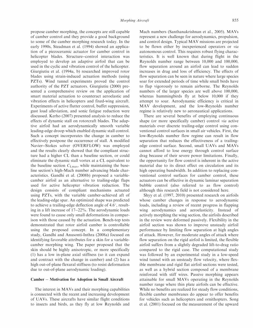
propose camber morphing, the concepts are still capableof camber control and they provide a good backgroundto some of the camber morphing research today. In theearly 1990s, Steadman et al. (1994) showed an applica-tion of a piezoceramic actuator for camber control inhelicopter blades. Structure!control interaction wasemployed to develop an adaptive airfoil that can beused in the cyclic and vibration control of the helicopter.Giurgiutiu et al. (1994a, b) researched improved rotorblades using strain-induced actuation methods (usingPZTs). Wind tunnel experiments proved the controlauthority of the PZT actuators. Giurgiutiu (2000) pre-sented a comprehensive review on the application ofsmart material actuation to counteract aeroelastic andvibration effects in helicopters and fixed-wing aircraft.Experiments of active flutter control, buffet suppression,gust load alleviation, and sonic fatigue reduction werediscussed. Kerho (2007) presented analysis to reduce theeffects of dynamic stall on rotorcraft blades. The adap-tive airfoil had an aerodynamically smooth variableleading-edge droop which enabled dynamic stall control.Such a concept incorporates the change in camber toeffectively postpone the occurrence of stall. A modifiedNavier!Stokes solver (OVERFLOW) was employedand the results clearly showed that the compliant struc-ture had a higher CL than a baseline section, or couldeliminate the dynamic stall vortex at a CL equivalent tothe baseline section CLmax, while maintaining the base-line section’s high-Mach number advancing blade char-acteristics. Gandhi et al. (2008b) proposed a variable-camber airfoil as an alternative to trailing-edge flapsused for active helicopter vibration reduction. Thedesign consists of compliant mechanisms actuatedusing PZTs, with the variable camber-achieved aft ofthe leading-edge spar. An optimized shape was predictedto achieve a trailing-edge deflection angle of 4.6#, result-ing in a lift increase of 17!22%. The aerodynamic loadswere found to cause only small deformations in compar-ison with those caused by the actuation. Bench-top testsdemonstrated that rotor airfoil camber is controllableusing the proposed concept. In a complementarystudy, Gandhi and Anusonti-Inthra (2008a) focused onidentifying favorable attributes for a skin for a variable-camber morphing wing. The paper proposed that theskin should be highly anisotropic, or more specifically(1) has a low in-plane axial stiffness (so it can expandand contract with the change in camber) and (2) has ahigh out-of-plane flexural stiffness (to resist deformationdue to out-of-plane aerodynamic loading).
Camber ! Motivation for Adoption in Small Aircraft
The interest in MAVs and their morphing capabilitiesis connected with the recent and increasing developmentof UAVs. These aircrafts have similar flight conditionsto insects and birds, as they fly at low Reynolds and
Mach numbers (Santhanakrishnan et al., 2005). MAVsrepresent a new challenge for aerodynamics, propulsion,and control design. Typical MAV missions are projectedto be flown either by inexperienced operators or viaautonomous control. This requires robust flying charac-teristics. It is well known that during flight in theReynolds number range between 10,000 and 100,000,flow separation around an airfoil can lead to suddenincreases in drag and loss of efficiency. The effects offlow separation can be seen in nature where large speciessoar for extended periods of time while small birds haveto flap vigorously to remain airborne. The Reynoldsnumbers of the larger species are well above 100,000,whereas hummingbirds fly at below 10,000 if theyattempt to soar. Aerodynamic efficiency is critical inMAV development, and the low-Reynolds numberregime is relatively new to aeronautical applications.
There are several benefits of employing continuousshape (or more specifically camber) control via activematerials over discrete trailing-edge control using con-ventional control surfaces in small air vehicles. First, thelow-Reynolds number flow regime can result in flowseparation that reduces the effectiveness of a trailing-edge control surface. Second, small UAVs and MAVscannot afford to lose energy through control surfacedrag because of their severe power limitations. Finally,the opportunity for flow control is inherent in the activematerial due to its direct effect on circulation and itshigh operating bandwidth. In addition to replacing con-ventional control surfaces for camber control, theseactuators can be effective in dynamic laminar separationbubble control (also referred to as flow control)although this research field is not considered here.
Shyy et al. (1997, 2010) presented research on airfoilswhose camber changes in response to aerodynamicloads, including a review of recent progress in flappingwing aerodynamics and aeroelasticity. Instead ofactively morphing the wing section, the airfoils describedin the review were deformed passively. Flexibility in theairfoil section was shown to improve unsteady airfoilperformance by limiting flow separation at high anglesof attack. However, for moderate angles of attack whereflow separation on the rigid airfoil is limited, the flexibleairfoil suffers from a slightly degraded lift-to-drag ratiocompared to the rigid case. The computational studywas followed by an experimental study in a low-speedwind tunnel with an unsteady flow velocity, where flex-ible membrane and rigid flat airfoil sections were tested,as well as a hybrid section composed of a membranereinforced with stiff wires. Passive morphing appearsattainable for small MAVs operating in the Reynoldsnumber range where thin plate airfoils can be effective.While no benefits are realized for steady flow conditions,flexible camber membranes do appear to offer benefitsfor vehicles such as helicopters and ornithopters. Songet al. (2001) focused on the measurement of the upward
Morphing Aircraft 855
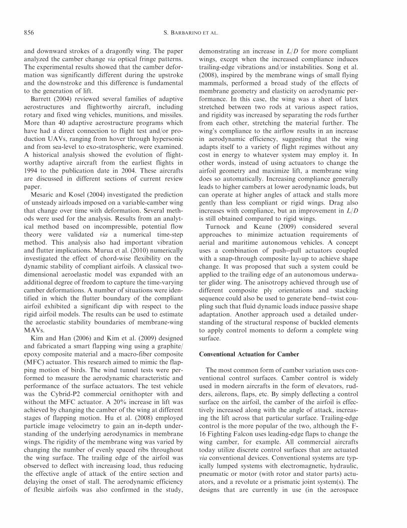
and downward strokes of a dragonfly wing. The paperanalyzed the camber change via optical fringe patterns.The experimental results showed that the camber defor-mation was significantly different during the upstrokeand the downstroke and this difference is fundamentalto the generation of lift.Barrett (2004) reviewed several families of adaptive
aerostructures and flightworthy aircraft, includingrotary and fixed wing vehicles, munitions, and missiles.More than 40 adaptive aerostructure programs whichhave had a direct connection to flight test and/or pro-duction UAVs, ranging from hover through hypersonicand from sea-level to exo-stratospheric, were examined.A historical analysis showed the evolution of flight-worthy adaptive aircraft from the earliest flights in1994 to the publication date in 2004. These aircraftsare discussed in different sections of current reviewpaper.Mesaric and Kosel (2004) investigated the prediction
of unsteady airloads imposed on a variable-camber wingthat change over time with deformation. Several meth-ods were used for the analysis. Results from an analyt-ical method based on incompressible, potential flowtheory were validated via a numerical time-stepmethod. This analysis also had important vibrationand flutter implications. Murua et al. (2010) numericallyinvestigated the effect of chord-wise flexibility on thedynamic stability of compliant airfoils. A classical two-dimensional aeroelastic model was expanded with anadditional degree of freedom to capture the time-varyingcamber deformations. A number of situations were iden-tified in which the flutter boundary of the compliantairfoil exhibited a significant dip with respect to therigid airfoil models. The results can be used to estimatethe aeroelastic stability boundaries of membrane-wingMAVs.Kim and Han (2006) and Kim et al. (2009) designed
and fabricated a smart flapping wing using a graphite/epoxy composite material and a macro-fiber composite(MFC) actuator. This research aimed to mimic the flap-ping motion of birds. The wind tunnel tests were per-formed to measure the aerodynamic characteristic andperformance of the surface actuators. The test vehiclewas the Cybrid-P2 commercial ornithopter with andwithout the MFC actuator. A 20% increase in lift wasachieved by changing the camber of the wing at differentstages of flapping motion. Hu et al. (2008) employedparticle image velocimetry to gain an in-depth under-standing of the underlying aerodynamics in membranewings. The rigidity of the membrane wing was varied bychanging the number of evenly spaced ribs throughoutthe wing surface. The trailing edge of the airfoil wasobserved to deflect with increasing load, thus reducingthe effective angle of attack of the entire section anddelaying the onset of stall. The aerodynamic efficiencyof flexible airfoils was also confirmed in the study,
demonstrating an increase in L/D for more compliantwings, except when the increased compliance inducestrailing-edge vibrations and/or instabilities. Song et al.(2008), inspired by the membrane wings of small flyingmammals, performed a broad study of the effects ofmembrane geometry and elasticity on aerodynamic per-formance. In this case, the wing was a sheet of latexstretched between two rods at various aspect ratios,and rigidity was increased by separating the rods furtherfrom each other, stretching the material further. Thewing’s compliance to the airflow results in an increasein aerodynamic efficiency, suggesting that the wingadapts itself to a variety of flight regimes without anycost in energy to whatever system may employ it. Inother words, instead of using actuators to change theairfoil geometry and maximize lift, a membrane wingdoes so automatically. Increasing compliance generallyleads to higher cambers at lower aerodynamic loads, butcan operate at higher angles of attack and stalls moregently than less compliant or rigid wings. Drag alsoincreases with compliance, but an improvement in L/Dis still obtained compared to rigid wings.
Turnock and Keane (2009) considered severalapproaches to minimize actuation requirements ofaerial and maritime autonomous vehicles. A conceptuses a combination of push!pull actuators coupledwith a snap-through composite lay-up to achieve shapechange. It was proposed that such a system could beapplied to the trailing edge of an autonomous underwa-ter glider wing. The anisotropy achieved through use ofdifferent composite ply orientations and stackingsequence could also be used to generate bend!twist cou-pling such that fluid dynamic loads induce passive shapeadaptation. Another approach used a detailed under-standing of the structural response of buckled elementsto apply control moments to deform a complete wingsurface.
Conventional Actuation for Camber
The most common form of camber variation uses con-ventional control surfaces. Camber control is widelyused in modern aircrafts in the form of elevators, rud-ders, ailerons, flaps, etc. By simply deflecting a controlsurface on the airfoil, the camber of the airfoil is effec-tively increased along with the angle of attack, increas-ing the lift across that particular surface. Trailing-edgecontrol is the more popular of the two, although the F-16 Fighting Falcon uses leading-edge flaps to change thewing camber, for example. All commercial aircraftstoday utilize discrete control surfaces that are actuatedvia conventional devices. Conventional systems are typ-ically lumped systems with electromagnetic, hydraulic,pneumatic or motor (with rotor and stator parts) actu-ators, and a revolute or a prismatic joint system(s). Thedesigns that are currently in use (in the aerospace
856 S. BARBARINO ET AL.
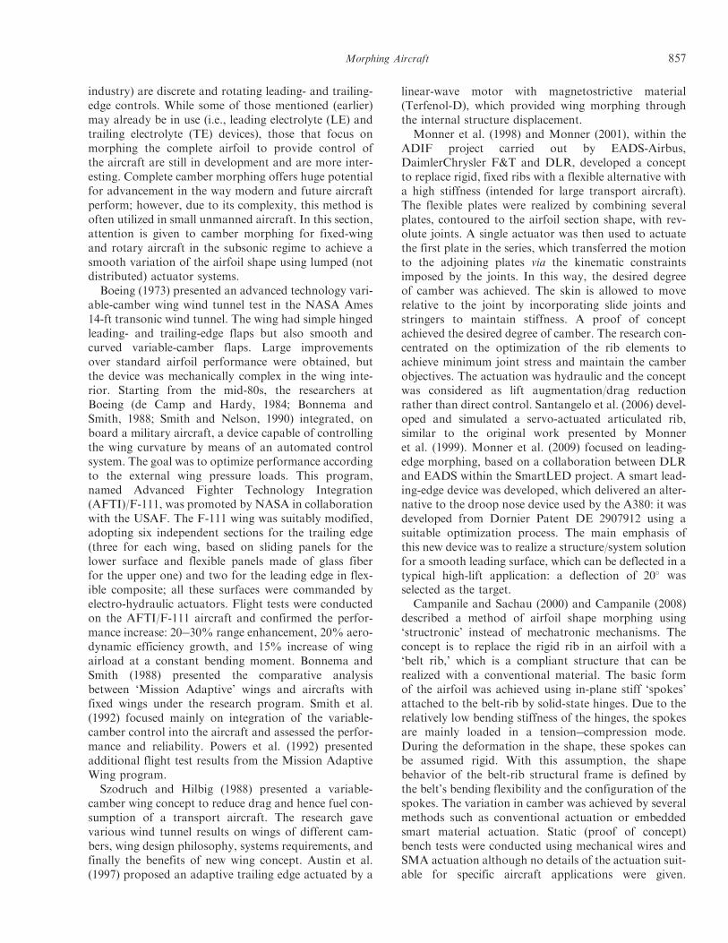
industry) are discrete and rotating leading- and trailing-edge controls. While some of those mentioned (earlier)may already be in use (i.e., leading electrolyte (LE) andtrailing electrolyte (TE) devices), those that focus onmorphing the complete airfoil to provide control ofthe aircraft are still in development and are more inter-esting. Complete camber morphing offers huge potentialfor advancement in the way modern and future aircraftperform; however, due to its complexity, this method isoften utilized in small unmanned aircraft. In this section,attention is given to camber morphing for fixed-wingand rotary aircraft in the subsonic regime to achieve asmooth variation of the airfoil shape using lumped (notdistributed) actuator systems.Boeing (1973) presented an advanced technology vari-
able-camber wing wind tunnel test in the NASA Ames14-ft transonic wind tunnel. The wing had simple hingedleading- and trailing-edge flaps but also smooth andcurved variable-camber flaps. Large improvementsover standard airfoil performance were obtained, butthe device was mechanically complex in the wing inte-rior. Starting from the mid-80s, the researchers atBoeing (de Camp and Hardy, 1984; Bonnema andSmith, 1988; Smith and Nelson, 1990) integrated, onboard a military aircraft, a device capable of controllingthe wing curvature by means of an automated controlsystem. The goal was to optimize performance accordingto the external wing pressure loads. This program,named Advanced Fighter Technology Integration(AFTI)/F-111, was promoted by NASA in collaborationwith the USAF. The F-111 wing was suitably modified,adopting six independent sections for the trailing edge(three for each wing, based on sliding panels for thelower surface and flexible panels made of glass fiberfor the upper one) and two for the leading edge in flex-ible composite; all these surfaces were commanded byelectro-hydraulic actuators. Flight tests were conductedon the AFTI/F-111 aircraft and confirmed the perfor-mance increase: 20!30% range enhancement, 20% aero-dynamic efficiency growth, and 15% increase of wingairload at a constant bending moment. Bonnema andSmith (1988) presented the comparative analysisbetween ‘Mission Adaptive’ wings and aircrafts withfixed wings under the research program. Smith et al.(1992) focused mainly on integration of the variable-camber control into the aircraft and assessed the perfor-mance and reliability. Powers et al. (1992) presentedadditional flight test results from the Mission AdaptiveWing program.Szodruch and Hilbig (1988) presented a variable-
camber wing concept to reduce drag and hence fuel con-sumption of a transport aircraft. The research gavevarious wind tunnel results on wings of different cam-bers, wing design philosophy, systems requirements, andfinally the benefits of new wing concept. Austin et al.(1997) proposed an adaptive trailing edge actuated by a
linear-wave motor with magnetostrictive material(Terfenol-D), which provided wing morphing throughthe internal structure displacement.
Monner et al. (1998) and Monner (2001), within theADIF project carried out by EADS-Airbus,DaimlerChrysler F&T and DLR, developed a conceptto replace rigid, fixed ribs with a flexible alternative witha high stiffness (intended for large transport aircraft).The flexible plates were realized by combining severalplates, contoured to the airfoil section shape, with rev-olute joints. A single actuator was then used to actuatethe first plate in the series, which transferred the motionto the adjoining plates via the kinematic constraintsimposed by the joints. In this way, the desired degreeof camber was achieved. The skin is allowed to moverelative to the joint by incorporating slide joints andstringers to maintain stiffness. A proof of conceptachieved the desired degree of camber. The research con-centrated on the optimization of the rib elements toachieve minimum joint stress and maintain the camberobjectives. The actuation was hydraulic and the conceptwas considered as lift augmentation/drag reductionrather than direct control. Santangelo et al. (2006) devel-oped and simulated a servo-actuated articulated rib,similar to the original work presented by Monneret al. (1999). Monner et al. (2009) focused on leading-edge morphing, based on a collaboration between DLRand EADS within the SmartLED project. A smart lead-ing-edge device was developed, which delivered an alter-native to the droop nose device used by the A380: it wasdeveloped from Dornier Patent DE 2907912 using asuitable optimization process. The main emphasis ofthis new device was to realize a structure/system solutionfor a smooth leading surface, which can be deflected in atypical high-lift application: a deflection of 20# wasselected as the target.
Campanile and Sachau (2000) and Campanile (2008)described a method of airfoil shape morphing using‘structronic’ instead of mechatronic mechanisms. Theconcept is to replace the rigid rib in an airfoil with a‘belt rib,’ which is a compliant structure that can berealized with a conventional material. The basic formof the airfoil was achieved using in-plane stiff ‘spokes’attached to the belt-rib by solid-state hinges. Due to therelatively low bending stiffness of the hinges, the spokesare mainly loaded in a tension!compression mode.During the deformation in the shape, these spokes canbe assumed rigid. With this assumption, the shapebehavior of the belt-rib structural frame is defined bythe belt’s bending flexibility and the configuration of thespokes. The variation in camber was achieved by severalmethods such as conventional actuation or embeddedsmart material actuation. Static (proof of concept)bench tests were conducted using mechanical wires andSMA actuation although no details of the actuation suit-able for specific aircraft applications were given.
Morphing Aircraft 857
Bartley-Cho et al. (2004) presented the smooth variable-camber wing that was applied in a Northrop GrummanUCAV test model (part of the Smart Wing Program,discussed in the next section). The unmanned aircraftdemonstrated high actuation rate (80#/s), large deflec-tion (20#), hinge-less, smoothly contoured control sur-faces with chord-wise and span-wise shape variabilities.Ultrasonic (piezoelectric material driven) motors wereused as actuators. van Dam (2002) presented a compre-hensive review of recent developments in aerodynamicdesign and analysis methods for multi-element high-liftsystems on transport airplanes. Attention was given tothe associated mechanical and cost problems since amulti-element high-lift system must be as simple andeconomical as possible while meeting the required aero-dynamic performance levels.Poonsong (2004) designed and implemented a multi-
section wing model based on the NACA 0012 airfoil,capable of variable curvature. Each rib was dividedinto six sections, each able to rotate up to 5# with respectto the previous one without significant discontinuities onthe wing surface. The camber change was obtained bymeans of pneumatic actuators. Wind tunnel testsshowed that the lift produced by a similar wing wascomparable to that of the same one piece airfoil, butthe surface drag was higher due to the increased requiredflexibility of the skin. Baker et al. (2005) and Baker andFriswell (2006, 2009) proposed a compliant structure toeffect a change in airfoil camber. The trailing edge of theairfoil section was morphed using a combination of 3 or88 actuators placed within 14- or 1752-element trussstructures, respectively. The trusses supported anddefined the shape of the airfoil. The focus of the paperwas to select which truss elements to replace by activematerials capable of extending or contracting theirlength while minimizing the required actuation strain.Several optimization algorithms were evaluated ! thebest optimization being performed by a relatively time-consuming genetic algorithm (GA). This sort of conceptis well suited to actuation by SMAs or piezoelectricstacks.Bornengo et al. (2005) examined a possible internal
wing structure that is adaptive to shape/camber changes.The chiral honeycomb design differed from classicalwing box structures and presented unique structuralbehavior in terms of its effective Poisson’s ratio. Thepaper details the numerical finite element analysismodels used to better predict a homogenized materialbehavior. It was determined that the material wouldchange camber with changes in flow speed. Gern et al.(2005) proposed the replacement of trailing-edge flapsby distributed structural actuation. The power require-ments for the actuation of the conventional flaps werecompared to that of the morphing wing design.Lajux and Fielding (2005) developed a new method-
ology for wing leading-edge devices for variable camber
applications. The research provided insight into CFDsimulation, new mechanism design solutions, and struc-tural analysis. It also described estimation methods forweight and reliability and trade-off studies of alternativeconfigurations. The methodology proposed aimed tospeed up the design process while incorporating the var-iable camber technology. A comparative study betweenconventional LE mechanisms and variable camber tech-nology was also given. Edi and Fielding (2006) examinedthe viability of using variable camber airfoils on trans-port aircraft. An airfoil employing hybrid laminar-flowcontrol (at the LE) and variable camber (at the TE) wasconsidered and a three-dimensional CFD analysis usedto determine the aerodynamic properties of the design.Diaconu et al. (2008) presented a non-linear staticfinite element study of a morphing airfoil to deter-mine the forces required for various levels of deflectionfor a graphite/epoxy composite material. The study pro-posed three bi-stable concepts and the respective geo-metric properties, including a control surface fixedbetween two vertical spars with a bi-stable adaptivetrailing edge.
Flexsys Inc. (2011; Website) focused on the aerody-namic smoothness of the wing and developed a func-tional, seamless, hinge-free wing whose trailing and/orleading edges morphed on demand to adapt to differentflight conditions. Kota et al. (2009) presented results(from Flexsys) on the variable-camber trailing edge fora high-altitude, long-endurance aircraft. The flight test-ing of the Mission Adaptive Compliant Wing adaptivestructure trailing-edge flap used in conjunction with anatural laminar flow airfoil was described. The airfoilflap system was optimized to maximize the laminarboundary layer extent over a broad lift coefficientrange for endurance aircraft applications. The wingwas flight tested (in 2006) at full-scale dynamic pressure,full-scale Mach number, and reduced-scale Reynoldsnumbers on the Scaled Composites White Knight air-craft. Data from flight testing revealed that laminar flowwas maintained over approximately 60% of the airfoilchord for much of the lift range. Drag results were pro-vided based on a dynamic pressure scaling factor toaccount for White Knight fuselage and wing interferenceeffects. The expanded ‘laminar bucket’ capability allowsthe endurance aircraft to significantly extend its range(15% or more) by continuously optimizing the wing L/Dthroughout the mission.
Frank et al. (2008) mechanized a controlled spanwise-varying airfoil camber change for a high-aspect ratiowing, resulting in optimized aerodynamic performancefor an aircraft that changed weight by 50% over its mis-sion. Two separate design methodologies were used toachieve these shape changes: (1) a rigid body kinematicsapproach and (2) a compliant mechanism approach. Aframework to optimize these two mechanisms was pre-sented. The designed mechanisms were evaluated based
858 S. BARBARINO ET AL.
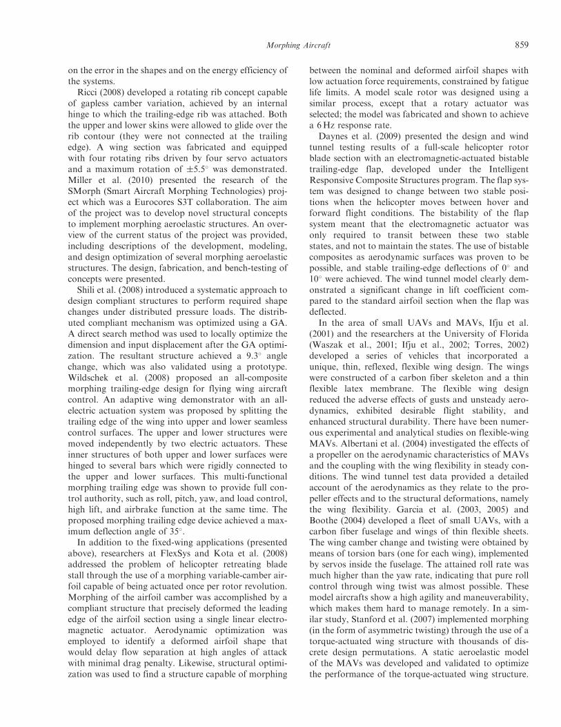
on the error in the shapes and on the energy efficiency ofthe systems.Ricci (2008) developed a rotating rib concept capable
of gapless camber variation, achieved by an internalhinge to which the trailing-edge rib was attached. Boththe upper and lower skins were allowed to glide over therib contour (they were not connected at the trailingedge). A wing section was fabricated and equippedwith four rotating ribs driven by four servo actuatorsand a maximum rotation of $5.5# was demonstrated.Miller et al. (2010) presented the research of theSMorph (Smart Aircraft Morphing Technologies) proj-ect which was a Eurocores S3T collaboration. The aimof the project was to develop novel structural conceptsto implement morphing aeroelastic structures. An over-view of the current status of the project was provided,including descriptions of the development, modeling,and design optimization of several morphing aeroelasticstructures. The design, fabrication, and bench-testing ofconcepts were presented.Shili et al. (2008) introduced a systematic approach to
design compliant structures to perform required shapechanges under distributed pressure loads. The distrib-uted compliant mechanism was optimized using a GA.A direct search method was used to locally optimize thedimension and input displacement after the GA optimi-zation. The resultant structure achieved a 9.3# anglechange, which was also validated using a prototype.Wildschek et al. (2008) proposed an all-compositemorphing trailing-edge design for flying wing aircraftcontrol. An adaptive wing demonstrator with an all-electric actuation system was proposed by splitting thetrailing edge of the wing into upper and lower seamlesscontrol surfaces. The upper and lower structures weremoved independently by two electric actuators. Theseinner structures of both upper and lower surfaces werehinged to several bars which were rigidly connected tothe upper and lower surfaces. This multi-functionalmorphing trailing edge was shown to provide full con-trol authority, such as roll, pitch, yaw, and load control,high lift, and airbrake function at the same time. Theproposed morphing trailing edge device achieved a max-imum deflection angle of 35#.In addition to the fixed-wing applications (presented
above), researchers at FlexSys and Kota et al. (2008)addressed the problem of helicopter retreating bladestall through the use of a morphing variable-camber air-foil capable of being actuated once per rotor revolution.Morphing of the airfoil camber was accomplished by acompliant structure that precisely deformed the leadingedge of the airfoil section using a single linear electro-magnetic actuator. Aerodynamic optimization wasemployed to identify a deformed airfoil shape thatwould delay flow separation at high angles of attackwith minimal drag penalty. Likewise, structural optimi-zation was used to find a structure capable of morphing
between the nominal and deformed airfoil shapes withlow actuation force requirements, constrained by fatiguelife limits. A model scale rotor was designed using asimilar process, except that a rotary actuator wasselected; the model was fabricated and shown to achievea 6Hz response rate.
Daynes et al. (2009) presented the design and windtunnel testing results of a full-scale helicopter rotorblade section with an electromagnetic-actuated bistabletrailing-edge flap, developed under the IntelligentResponsive Composite Structures program. The flap sys-tem was designed to change between two stable posi-tions when the helicopter moves between hover andforward flight conditions. The bistability of the flapsystem meant that the electromagnetic actuator wasonly required to transit between these two stablestates, and not to maintain the states. The use of bistablecomposites as aerodynamic surfaces was proven to bepossible, and stable trailing-edge deflections of 0# and10# were achieved. The wind tunnel model clearly dem-onstrated a significant change in lift coefficient com-pared to the standard airfoil section when the flap wasdeflected.
In the area of small UAVs and MAVs, Ifju et al.(2001) and the researchers at the University of Florida(Waszak et al., 2001; Ifju et al., 2002; Torres, 2002)developed a series of vehicles that incorporated aunique, thin, reflexed, flexible wing design. The wingswere constructed of a carbon fiber skeleton and a thinflexible latex membrane. The flexible wing designreduced the adverse effects of gusts and unsteady aero-dynamics, exhibited desirable flight stability, andenhanced structural durability. There have been numer-ous experimental and analytical studies on flexible-wingMAVs. Albertani et al. (2004) investigated the effects ofa propeller on the aerodynamic characteristics of MAVsand the coupling with the wing flexibility in steady con-ditions. The wind tunnel test data provided a detailedaccount of the aerodynamics as they relate to the pro-peller effects and to the structural deformations, namelythe wing flexibility. Garcia et al. (2003, 2005) andBoothe (2004) developed a fleet of small UAVs, with acarbon fiber fuselage and wings of thin flexible sheets.The wing camber change and twisting were obtained bymeans of torsion bars (one for each wing), implementedby servos inside the fuselage. The attained roll rate wasmuch higher than the yaw rate, indicating that pure rollcontrol through wing twist was almost possible. Thesemodel aircrafts show a high agility and maneuverability,which makes them hard to manage remotely. In a sim-ilar study, Stanford et al. (2007) implemented morphing(in the form of asymmetric twisting) through the use of atorque-actuated wing structure with thousands of dis-crete design permutations. A static aeroelastic modelof the MAVs was developed and validated to optimizethe performance of the torque-actuated wing structure.
Morphing Aircraft 859
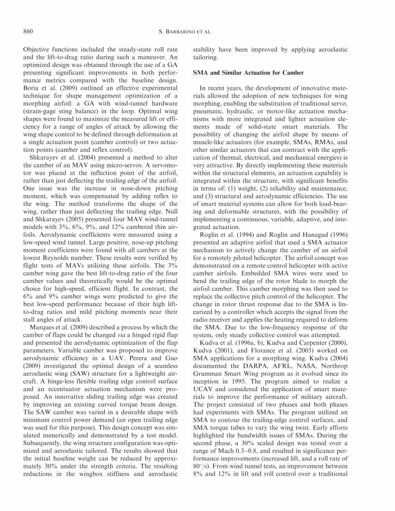
Objective functions included the steady-state roll rateand the lift-to-drag ratio during such a maneuver. Anoptimized design was obtained through the use of a GApresenting significant improvements in both perfor-mance metrics compared with the baseline design.Boria et al. (2009) outlined an effective experimentaltechnique for shape management optimization of amorphing airfoil: a GA with wind-tunnel hardware(strain-gage sting balance) in the loop. Optimal wingshapes were found to maximize the measured lift or effi-ciency for a range of angles of attack by allowing thewing shape control to be defined through deformation ata single actuation point (camber control) or two actua-tion points (camber and reflex control).Shkarayev et al. (2004) presented a method to alter
the camber of an MAV using micro-servos. A servomo-tor was placed at the inflection point of the airfoil,rather than just deflecting the trailing edge of the airfoil.One issue was the increase in nose-down pitchingmoment, which was compensated by adding reflex tothe wing. The method transforms the shape of thewing, rather than just deflecting the trailing edge. Nulland Shkarayev (2005) presented four MAV wind-tunnelmodels with 3%, 6%, 9%, and 12% cambered thin air-foils. Aerodynamic coefficients were measured using alow-speed wind tunnel. Large positive, nose-up pitchingmoment coefficients were found with all cambers at thelowest Reynolds number. These results were verified byflight tests of MAVs utilizing these airfoils. The 3%camber wing gave the best lift-to-drag ratio of the fourcamber values and theoretically would be the optimalchoice for high-speed, efficient flight. In contrast, the6% and 9% camber wings were predicted to give thebest low-speed performance because of their high lift-to-drag ratios and mild pitching moments near theirstall angles of attack.Marques et al. (2009) described a process by which the
camber of flaps could be changed via a hinged rigid flapand presented the aerodynamic optimization of the flapparameters. Variable camber was proposed to improveaerodynamic efficiency in a UAV. Perera and Guo(2009) investigated the optimal design of a seamlessaeroelastic wing (SAW) structure for a lightweight air-craft. A hinge-less flexible trailing edge control surfaceand an eccentuator actuation mechanism were pro-posed. An innovative sliding trailing edge was createdby improving an existing curved torque beam design.The SAW camber was varied in a desirable shape withminimum control power demand (an open trailing edgewas used for this purpose). This design concept was sim-ulated numerically and demonstrated by a test model.Subsequently, the wing structure configuration was opti-mized and aeroelastic tailored. The results showed thatthe initial baseline weight can be reduced by approxi-mately 30% under the strength criteria. The resultingreductions in the wingbox stiffness and aeroelastic
stability have been improved by applying aeroelastictailoring.
SMA and Similar Actuation for Camber
In recent years, the development of innovative mate-rials allowed the adoption of new techniques for wingmorphing, enabling the substitution of traditional servo,pneumatic, hydraulic, or motor-like actuation mecha-nisms with more integrated and lighter actuation ele-ments made of solid-state smart materials. Thepossibility of changing the airfoil shape by means ofmuscle-like actuators (for example, SMAs, RMAs, andother similar actuators that can contract with the appli-cation of thermal, electrical, and mechanical energies) isvery attractive. By directly implementing these materialswithin the structural elements, an actuation capability isintegrated within the structure, with significant benefitsin terms of: (1) weight, (2) reliability and maintenance,and (3) structural and aerodynamic efficiencies. The useof smart material systems can allow for both load-bear-ing and deformable structures, with the possibility ofimplementing a continuous, variable, adaptive, and inte-grated actuation.
Roglin et al. (1994) and Roglin and Hanagud (1996)presented an adaptive airfoil that used a SMA actuatormechanism to actively change the camber of an airfoilfor a remotely piloted helicopter. The airfoil concept wasdemonstrated on a remote control helicopter with activecamber airfoils. Embedded SMA wires were used tobend the trailing edge of the rotor blade to morph theairfoil camber. This camber morphing was then used toreplace the collective pitch control of the helicopter. Thechange in rotor thrust response due to the SMA is lin-earized by a controller which accepts the signal from theradio receiver and applies the heating required to deformthe SMA. Due to the low-frequency response of thesystem, only steady collective control was attempted.
Kudva et al. (1996a, b), Kudva and Carpenter (2000),Kudva (2001), and Florance et al. (2003) worked onSMA applications for a morphing wing. Kudva (2004)documented the DARPA, AFRL, NASA, NorthropGrumman Smart Wing program as it evolved since itsinception in 1995. The program aimed to realize aUCAV and considered the application of smart mate-rials to improve the performance of military aircraft.The project consisted of two phases and both phaseshad experiments with SMAs. The program utilized anSMA to contour the trailing-edge control surfaces, andSMA torque tubes to vary the wing twist. Early effortshighlighted the bandwidth issues of SMAs. During thesecond phase, a 30% scaled design was tested over arange of Mach 0.3!0.8, and resulted in significance per-formance improvements (increased lift, and a roll rate of80#/s). From wind tunnel tests, an improvement between8% and 12% in lift and roll control over a traditional
860 S. BARBARINO ET AL.
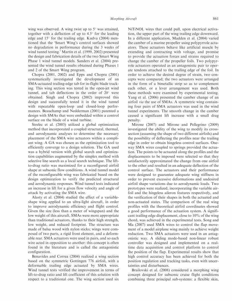
wing was observed. A wing twist up to 5# was attained,together with a deflection of up to 4.5# for the leadingedge and 15# for the trailing edge. Kudva (2004) men-tioned that the ‘Smart Wing’s control surfaces showedno degradation in performance during the 3 weeks ofwind tunnel testing.’ Martin et al. (1999, 2002) presentedthe design and fabrication details of the two Smart WingPhase 1 wind tunnel models. Sanders et al. (2004) pre-sented the wind tunnel results obtained during Phases 1and 2 of the Smart Wing program.Chopra (2001, 2002) and Epps and Chopra (2001)
systematically investigated the development of anSMA-actuated trailing-edge tab for in-flight blade track-ing. This wing section was tested in the open-jet windtunnel, and tab deflections in the order of 20# wereobtained. Singh and Chopra (2002) improved thisdesign and successfully tested it in the wind tunnelwith repeatable open-loop and closed-loop perfor-mances. Beauchamp and Nedderman (2001) patented adesign with SMAs that were embedded within a controlsurface on the blade of a wind turbine.Strelec et al. (2003) utilized a global optimization
method that incorporated a coupled structural, thermal,and aerodynamic analyses to determine the necessaryplacement of the SMA wire actuators within a compli-ant wing. A GA was chosen as the optimization tool toefficiently converge to a design solution. The GA usedwas a hybrid version with global search and optimiza-tion capabilities augmented by the simplex method withselective line search as a local search technique. The lift-to-drag ratio was maximized for a reconfigured airfoilshape at subsonic flow conditions. A wind tunnel modelof the reconfigurable wing was fabricated based on thedesign optimization to verify the predicted structuraland aerodynamic responses. Wind tunnel tests indicatedan increase in lift for a given flow velocity and angle ofattack by activating the SMA wire.Alasty et al. (2004) studied the effect of a variable-
shape wing applied to an ultra-light aircraft, in orderto improve aerodynamic efficiency and flight control.Given the size (less than a meter of wingspan) and thelow weight of this aircraft, SMAs were more appropriatethan traditional actuators, thanks to their high strength,low weight, and reduced footprint. The structure wasmade of balsa wood with nylon sticks; wings were com-posed of two parts, a rigid front element, and a deform-able rear. SMA actuators were used in pairs, and so eachwire acted in opposition to another: this concept is oftenfound in the literature and is called the antagonisticconfiguration.Benavides and Correa (2004) realized a wing section
based on the symmetric Gottingen 776 airfoil, with adeformable trailing edge actuated by SMA wires.Wind tunnel tests verified the improvement in terms oflift-to-drag ratio and lift coefficient of this solution withrespect to a traditional one. The wing section used six
NiTiNOL wires that could pull, upon electrical activa-tion, the upper part of the wing trailing edge downward.In a different application, Madden et al. (2004) variedthe camber of a marine propeller using polypyrrole actu-ators. These actuators behave like artificial muscle byextending and contracting with voltage, and promiseto provide the actuation forces and strains required tochange the camber of the propeller foils. Two polypyr-role actuators operated as an antagonistic pair to oper-ate tendons attached to the trailing edge of the foil. Inorder to achieve the desired degree of strain, two con-cepts were compared; the two actuators were arrangedin the form of a bimetallic strip so as to complementeach other, or a lever arrangement was used. Boththese methods were examined by experimental testing.Yang et al. (2006) presented the camber change of anairfoil via the use of SMAs. A symmetric wing contain-ing four pairs of SMA actuators was used in the windtunnel experiments. The smooth change in the cambercaused a significant lift increase with a small dragpenalty.
Mirone (2007) and Mirone and Pellegrino (2009)investigated the ability of the wing to modify its cross-section (assuming the shape of two different airfoils) andthe possibility of deflecting the profiles near the trailingedge in order to obtain hingeless control surfaces. One-way SMA wires coupled to springs provided the actua-tion. The points to be actuated along the profiles and thedisplacements to be imposed were selected so that theysatisfactorily approximated the change from one airfoilto the other and resulted in an adequate deflection of thecontrol surface. The actuators and their performancewere designed to guarantee adequate wing stiffness inorder to prevent excessive deformations and undesiredairfoil shape variations due to aerodynamic loads. Twoprototypes were realized, incorporating the variable air-foil and the hingeless aileron features respectively, andthe verification of their shapes in both the actuated andnon-actuated states. The comparison of the real wingprofiles with the theoretical airfoil coordinates showeda good performance of the actuation system. A signifi-cant trailing edge displacement, close to 10% of the wingchord, was achieved in the experimental tests. Song andMa (2007) used SMA wires to control the flap move-ment of a model airplane wing mainly to achieve weightreduction. Two SMA actuators were used in an antag-onistic way. A sliding mode-based non-linear robustcontroller was designed and implemented on a real-time data acquisition and control platform to controlthe position of the flap. Experimental results show thathigh control accuracy has been achieved for both theposition regulation and tracking tasks, even with uncer-tainties and disturbances.
Brailovski et al. (2008) considered a morphing wingconcept designed for subsonic cruise flight conditionscombining three principal sub-systems: a flexible skin,
Morphing Aircraft 861
a rigid interior structure, and an actuator group locatedinside the wingbox. Using a weighted evaluation of theaerodynamic and mechanical performances in theframework of a multi-criteria optimization procedure,an adaptive structure consisting of a four-ply flexibleskin powered by two individually controlled actuatorswas designed. The forces these actuators must provide inorder to fit target wing profiles are calculated for a givenflexible structure and given flight conditions. Each actu-ator includes linear SMA active elements with oneextremity connected, through a cam transmissionsystem, to the flexible skins and other extremity con-nected to the rigid structure of the wing through a biasspring. To meet the functional requirements of the appli-cation, the geometry (length and cross-section) of theSMA active elements and the bias spring characteristicsare calculated.Peel et al. (2008, 2009) constructed a variable-camber
morphing wing using elastomeric composites as theinternal actuators. The skin of the wing was a carbonfiber and polyurethane elastomeric composite that wasable to flex in the chordwise direction. The actuatorswere RMAs. When pressurized with air, the RMAs con-tract with a force generally proportional to the appliedpressure. Similar to hydraulic systems, these actuatorsrequire pneumatic systems, which typically have aweight penalty of the supporting hardware (compressorand accumulator, or pressure storage vessel, solenoids,control circuitry). The RMA actuators were connectedto the leading and trailing edges of the wing; hence thecontraction would cause an increase in camber. Twogenerations of prototypes were described with signifi-cant improvements made on the second generation. Avery simple morphing wing was fabricated in phase one:the nose was able to elastically camber down by about25# and the tail by 20#. The second-generation wing fab-rication methodology showed smooth elastic camberingand no buckling or waviness in the skins. In thiscase, the LE and the TE achieved 23# and 15# deflec-tions, respectively. Chou and Philen (2008) presentedmorphing skins employing pressurized flexiblematrix composites (FMCs) for trailing-edge flap controlof a glider wing. The FMC skins consisted of embed-ded pressurized composite tubes in an elastomericresin. A mathematical model for a single pressurizedFMC composite tube was developed and the rule of mix-tures was employed to find the effective properties of themulti-tube active skin. A 2D vortex panel method esti-mated the aerodynamic loading on the trailing-edgeflaps.Popov et al. (2008) presented an adaptive wing
concept with an upper surface that deflected undersingle-point control. The flexible skin was placed atthe laminar!turbulent boundary layer transition point,and different functions were tested to find whether thetransition could be shifted toward the trailing edge and
whether drag could be reduced. In addition to staticdeflections, sinusoidal deflections are evaluated.
Seow et al. (2008) presented a study on morphingflaps actuated by SMA wires, including a theoreticalanalysis of the aerodynamic loading. A wing prototypewas designed and fabricated, and the actuation of theflap was demonstrated, achieving an actuation angle of5.2#. A second prototype achieved 15# deflection.Flexible skins were also explored and experimented.Finally, the controllability of the prototype was investi-gated, including the measurement and estimation ofpower consumption, and the dependence of heatingand cooling time on input variations. Abdullah et al.(2009) used SMAs to alter the shape of an airfoil toincrease the L/D ratio throughout the flight regime ofa UAV. A flexible skin was also utilized for variable-camber control. The aerodynamic effect of camber loca-tion and magnitude was analyzed using a 2D panel-method. The researchers found that shifting the locationof maximum camber thickness from 10% to 50% of thechord, and increasing the camber from 1% to 5%, max-imized L/D for low angles of attack. Ideally, the wingwould use this range to accommodate multiple flightconditions. The objective was predominantly cruise effi-ciency rather than control, and hence the response timeof the SMA was considered to be acceptable.
Barbarino et al. (2009a) investigated an active wing(via SMAs) that deformed its shape to provide a bumpedwing geometry. This variation in the wing thickness isadvantageous for transonic flight, but also has benefitsin subsonic flight. Benchtop experiments validated theefficacy of the concept. Barbarino et al. (2007, 2008,2009b) introduced several morphing trailing edge archi-tectures to replace a conventional flap device. A compli-ant rib structure was designed, based on SMA actuatorsexhibiting structural potential (i.e., bearing the externalaerodynamic loads). Numerical results, achievedthrough an FE approach, were presented in terms oftrailing edge-induced displacement and morphedshape. Barbarino et al. (2010a) proposed a flap architec-ture for a variable-camber trailing edge, whose referencegeometry was based on a full-scale wing for a regionaltransport aircraft. The compliant rib was based on atruss-like structure where some members were activerods made of SMA. The layout of the structure wasobtained using a preliminary optimization process,incorporating practical constraints, by focusing on abasic truss-like element and its repetition and positionwithin the overall truss. The structural performance wasestimated using FE analysis. The SMA behavior wasmodeled using a dedicated routine to evaluate the inter-nal stress state and the minimum activation temperature.The design fulfills a number of key requirements: asmooth actuation along the chord; morphed shapesthat assure the optimal aerodynamic load distributionfor high lift; light weight; and low mechanical
862 S. BARBARINO ET AL.
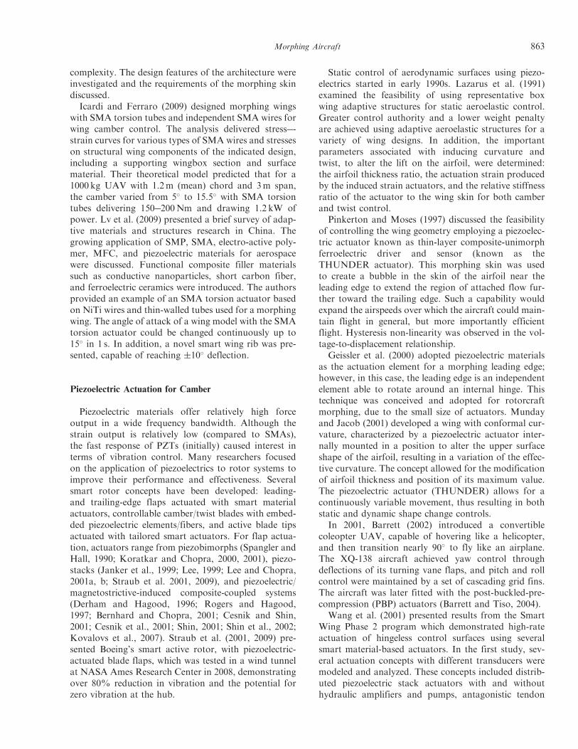
complexity. The design features of the architecture wereinvestigated and the requirements of the morphing skindiscussed.Icardi and Ferraro (2009) designed morphing wings
with SMA torsion tubes and independent SMA wires forwing camber control. The analysis delivered stress!-strain curves for various types of SMA wires and stresseson structural wing components of the indicated design,including a supporting wingbox section and surfacematerial. Their theoretical model predicted that for a1000 kg UAV with 1.2m (mean) chord and 3m span,the camber varied from 5# to 15.5# with SMA torsiontubes delivering 150!200Nm and drawing 1.2 kW ofpower. Lv et al. (2009) presented a brief survey of adap-tive materials and structures research in China. Thegrowing application of SMP, SMA, electro-active poly-mer, MFC, and piezoelectric materials for aerospacewere discussed. Functional composite filler materialssuch as conductive nanoparticles, short carbon fiber,and ferroelectric ceramics were introduced. The authorsprovided an example of an SMA torsion actuator basedon NiTi wires and thin-walled tubes used for a morphingwing. The angle of attack of a wing model with the SMAtorsion actuator could be changed continuously up to15# in 1 s. In addition, a novel smart wing rib was pre-sented, capable of reaching $10# deflection.
Piezoelectric Actuation for Camber
Piezoelectric materials offer relatively high forceoutput in a wide frequency bandwidth. Although thestrain output is relatively low (compared to SMAs),the fast response of PZTs (initially) caused interest interms of vibration control. Many researchers focusedon the application of piezoelectrics to rotor systems toimprove their performance and effectiveness. Severalsmart rotor concepts have been developed: leading-and trailing-edge flaps actuated with smart materialactuators, controllable camber/twist blades with embed-ded piezoelectric elements/fibers, and active blade tipsactuated with tailored smart actuators. For flap actua-tion, actuators range from piezobimorphs (Spangler andHall, 1990; Koratkar and Chopra, 2000, 2001), piezo-stacks (Janker et al., 1999; Lee, 1999; Lee and Chopra,2001a, b; Straub et al. 2001, 2009), and piezoelectric/magnetostrictive-induced composite-coupled systems(Derham and Hagood, 1996; Rogers and Hagood,1997; Bernhard and Chopra, 2001; Cesnik and Shin,2001; Cesnik et al., 2001; Shin, 2001; Shin et al., 2002;Kovalovs et al., 2007). Straub et al. (2001, 2009) pre-sented Boeing’s smart active rotor, with piezoelectric-actuated blade flaps, which was tested in a wind tunnelat NASA Ames Research Center in 2008, demonstratingover 80% reduction in vibration and the potential forzero vibration at the hub.
Static control of aerodynamic surfaces using piezo-electrics started in early 1990s. Lazarus et al. (1991)examined the feasibility of using representative boxwing adaptive structures for static aeroelastic control.Greater control authority and a lower weight penaltyare achieved using adaptive aeroelastic structures for avariety of wing designs. In addition, the importantparameters associated with inducing curvature andtwist, to alter the lift on the airfoil, were determined:the airfoil thickness ratio, the actuation strain producedby the induced strain actuators, and the relative stiffnessratio of the actuator to the wing skin for both camberand twist control.
Pinkerton and Moses (1997) discussed the feasibilityof controlling the wing geometry employing a piezoelec-tric actuator known as thin-layer composite-unimorphferroelectric driver and sensor (known as theTHUNDER actuator). This morphing skin was usedto create a bubble in the skin of the airfoil near theleading edge to extend the region of attached flow fur-ther toward the trailing edge. Such a capability wouldexpand the airspeeds over which the aircraft could main-tain flight in general, but more importantly efficientflight. Hysteresis non-linearity was observed in the vol-tage-to-displacement relationship.
Geissler et al. (2000) adopted piezoelectric materialsas the actuation element for a morphing leading edge;however, in this case, the leading edge is an independentelement able to rotate around an internal hinge. Thistechnique was conceived and adopted for rotorcraftmorphing, due to the small size of actuators. Mundayand Jacob (2001) developed a wing with conformal cur-vature, characterized by a piezoelectric actuator inter-nally mounted in a position to alter the upper surfaceshape of the airfoil, resulting in a variation of the effec-tive curvature. The concept allowed for the modificationof airfoil thickness and position of its maximum value.The piezoelectric actuator (THUNDER) allows for acontinuously variable movement, thus resulting in bothstatic and dynamic shape change controls.
In 2001, Barrett (2002) introduced a convertiblecoleopter UAV, capable of hovering like a helicopter,and then transition nearly 90# to fly like an airplane.The XQ-138 aircraft achieved yaw control throughdeflections of its turning vane flaps, and pitch and rollcontrol were maintained by a set of cascading grid fins.The aircraft was later fitted with the post-buckled-pre-compression (PBP) actuators (Barrett and Tiso, 2004).
Wang et al. (2001) presented results from the SmartWing Phase 2 program which demonstrated high-rateactuation of hingeless control surfaces using severalsmart material-based actuators. In the first study, sev-eral actuation concepts with different transducers weremodeled and analyzed. These concepts included distrib-uted piezoelectric stack actuators with and withouthydraulic amplifiers and pumps, antagonistic tendon
Morphing Aircraft 863
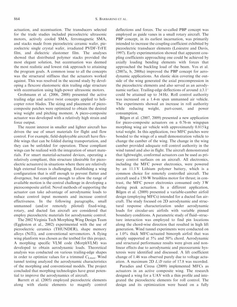
actuation, and eccentuation. The transducers selectedfor the trade studies included piezoelectric ultrasonicmotors, actively cooled SMA, ferromagnetic SMA,and stacks made from piezoelectric ceramic wafer, pie-zoelectric single crystal wafer, irradiated PVDF-TrFEfilm, and dielectric elastomer film. The analysesshowed that distributed polymer stacks provided themost elegant solution, but eccentuation was deemedthe most realistic and lowest risk approach to attainingthe program goals. A common issue to all the conceptswas the structural stiffness that the actuators workedagainst. This was resolved in the second study by devel-oping a flexcore elastomeric skin trailing edge structurewith eccentuation using high-power ultrasonic motors.Grohmann et al. (2006, 2008) presented the active
trailing edge and active twist concepts applied to heli-copter rotor blades. The sizing and placement of piezo-composite patches were optimized to obtain the desiredwing weight and pitching moment. A piezo-compositeactuator was developed with a relatively high strain andforce output.The recent interest in smaller and lighter aircraft has
driven the use of smart materials for flight and flowcontrol. For example, field-deployable aircraft have flex-ible wings that can be folded during transportation, andthey can be unfolded for operation. These compliantwings can be realized with the integration of smart mate-rials. For smart material-actuated devices, operating arelatively compliant, thin structure (desirable for piezo-electric actuators) in situations where there are relativelyhigh external forces is challenging. Establishing a wingconfiguration that is stiff enough to prevent flutter anddivergence, but compliant enough to allow the range ofavailable motion is the central challenge in developing apiezocomposite airfoil. Novel methods of supporting theactuator can take advantage of aerodynamic loads toreduce control input moments and increase controleffectiveness. In the following paragraphs, smallunmanned (and/or remotely piloted) fixed-wing,rotary, and ducted fan aircraft are considered thatemploy piezoelectric materials for aerodynamic control.The 2002 Virginia Tech Morphing Wing Design Team
(Eggleston et al., 2002) experimented with the use ofpiezoelectric ceramics (THUNDER), shape memoryalloys (NiTi), and conventional servomotors. A flyingwing planform was chosen as the testbed for this project.A morphing specific VLM code (MorphVLM) wasdeveloped to obtain aerodynamic loads. Theoreticalanalysis was conducted on various trailing-edge shapesin order to optimize values for a trimmed CLmax. Windtunnel testing analyzed the aerodynamic characteristicsof the morphing and conventional models. The projectconcluded that morphing technologies have great poten-tial to improve the aerodynamics of aircraft.Barrett et al. (2005) employed piezoelectric elements
along with elastic elements to magnify control
deflections and forces. The so-called PBP concept wasemployed as guide vanes in a small rotary aircraft. ThePBP concept, in its earliest incarnation, was primarilyintended to increase the coupling coefficient exhibited bypiezoelectric transducer elements (Lesieutre and Davis,1997). Early experimentation showed that apparent cou-pling coefficients approaching one could be achieved byaxially loading bending elements with forces thatapproached the buckling load of the beam. Vos et al.(2007a, b, 2008a) improved the PBP concept for aero-dynamic applications. An elastic skin covering the out-side of the wing generated the axial precompression inthe piezoelectric elements and also served as an aerody-namic surface. Trailing-edge deflections of around $3.1#
could be attained up to 34Hz. Roll control authoritywas increased on a 1.4-m span unmanned air vehicle.The experiments showed an increase in roll authoritywhile reducing weight, part-count, and powerconsumption.
Bilgen et al. (2007, 2009) presented a new applicationfor piezo-composite actuators on a 0.76-m wingspanmorphing wing air vehicle with approximately 0.815 kgtotal weight. In this application, two MFC patches werebonded to the wings of a small demonstration vehicle tochange the camber of the wing. The change in the wingcamber provided adequate roll control authority in thewind tunnel and also in flight. The aircraft demonstratedthat lightweight, conformal actuators can be used as pri-mary control surfaces on an aircraft. All electronics,including the MFC power electronics, were poweredby an 11.1V Lithium polymer battery, which is acommon choice for remotely controlled aircraft. Theaircraft used a 150-W brushless motor for thrust; in con-trast, the MFC power electronics consumed only 3Wduring peak actuation. In a different application,Bilgen et al. (2009) presented a variable-camber airfoildesign (employing MFCs) intended for a ducted fan air-craft. The study focused on 2D aerodynamic and struc-tural response characterization under aerodynamicloads for circular-arc airfoils with variable pinnedboundary conditions. A parametric study of fluid!struc-ture interaction was employed to find pin locationsalong the chord-wise direction that resulted in high liftgeneration. Wind tunnel experiments were conducted ona 1.0% thick MFC-actuated bimorph airfoil that wassimply supported at 5% and 50% chord. Aerodynamicand structural performance results were given and non-linear effects due to aerodynamic and piezoceramic hys-teresis were identified and discussed. A lift coefficientchange of 1.46 was observed purely due to voltage actu-ation. A maximum 2D L/D ratio of 17.8 was recorded.
Paradies and Ciresa (2009) implemented MFCs asactuators in an active composite wing. The researchdesigned a wing for a UAV with a thin profile and inte-grated the piezoelectric elements for roll control. Thedesign and its optimization were based on a fully
864 S. BARBARINO ET AL.
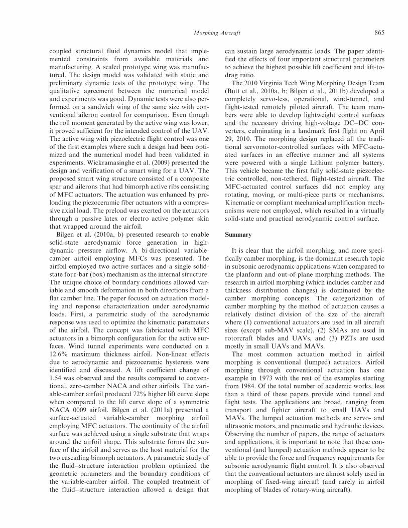
coupled structural fluid dynamics model that imple-mented constraints from available materials andmanufacturing. A scaled prototype wing was manufac-tured. The design model was validated with static andpreliminary dynamic tests of the prototype wing. Thequalitative agreement between the numerical modeland experiments was good. Dynamic tests were also per-formed on a sandwich wing of the same size with con-ventional aileron control for comparison. Even thoughthe roll moment generated by the active wing was lower,it proved sufficient for the intended control of the UAV.The active wing with piezoelectric flight control was oneof the first examples where such a design had been opti-mized and the numerical model had been validated inexperiments. Wickramasinghe et al. (2009) presented thedesign and verification of a smart wing for a UAV. Theproposed smart wing structure consisted of a compositespar and ailerons that had bimorph active ribs consistingof MFC actuators. The actuation was enhanced by pre-loading the piezoceramic fiber actuators with a compres-sive axial load. The preload was exerted on the actuatorsthrough a passive latex or electro active polymer skinthat wrapped around the airfoil.Bilgen et al. (2010a, b) presented research to enable
solid-state aerodynamic force generation in high-dynamic pressure airflow. A bi-directional variable-camber airfoil employing MFCs was presented. Theairfoil employed two active surfaces and a single solid-state four-bar (box) mechanism as the internal structure.The unique choice of boundary conditions allowed var-iable and smooth deformation in both directions from aflat camber line. The paper focused on actuation model-ing and response characterization under aerodynamicloads. First, a parametric study of the aerodynamicresponse was used to optimize the kinematic parametersof the airfoil. The concept was fabricated with MFCactuators in a bimorph configuration for the active sur-faces. Wind tunnel experiments were conducted on a12.6% maximum thickness airfoil. Non-linear effectsdue to aerodynamic and piezoceramic hysteresis wereidentified and discussed. A lift coefficient change of1.54 was observed and the results compared to conven-tional, zero-camber NACA and other airfoils. The vari-able-camber airfoil produced 72% higher lift curve slopewhen compared to the lift curve slope of a symmetricNACA 0009 airfoil. Bilgen et al. (2011a) presented asurface-actuated variable-camber morphing airfoilemploying MFC actuators. The continuity of the airfoilsurface was achieved using a single substrate that wrapsaround the airfoil shape. This substrate forms the sur-face of the airfoil and serves as the host material for thetwo cascading bimorph actuators. A parametric study ofthe fluid!structure interaction problem optimized thegeometric parameters and the boundary conditions ofthe variable-camber airfoil. The coupled treatment ofthe fluid!structure interaction allowed a design that
can sustain large aerodynamic loads. The paper identi-fied the effects of four important structural parametersto achieve the highest possible lift coefficient and lift-to-drag ratio.
The 2010 Virginia Tech Wing Morphing Design Team(Butt et al., 2010a, b; Bilgen et al., 2011b) developed acompletely servo-less, operational, wind-tunnel, andflight-tested remotely piloted aircraft. The team mem-bers were able to develop lightweight control surfacesand the necessary driving high-voltage DC!DC con-verters, culminating in a landmark first flight on April29, 2010. The morphing design replaced all the tradi-tional servomotor-controlled surfaces with MFC-actu-ated surfaces in an effective manner and all systemswere powered with a single Lithium polymer battery.This vehicle became the first fully solid-state piezoelec-tric controlled, non-tethered, flight-tested aircraft. TheMFC-actuated control surfaces did not employ anyrotating, moving, or multi-piece parts or mechanisms.Kinematic or compliant mechanical amplification mech-anisms were not employed, which resulted in a virtuallysolid-state and practical aerodynamic control surface.
Summary
It is clear that the airfoil morphing, and more speci-fically camber morphing, is the dominant research topicin subsonic aerodynamic applications when compared tothe planform and out-of-plane morphing methods. Theresearch in airfoil morphing (which includes camber andthickness distribution changes) is dominated by thecamber morphing concepts. The categorization ofcamber morphing by the method of actuation causes arelatively distinct division of the size of the aircraftwhere (1) conventional actuators are used in all aircraftsizes (except sub-MAV scale), (2) SMAs are used inrotorcraft blades and UAVs, and (3) PZTs are usedmostly in small UAVs and MAVs.
The most common actuation method in airfoilmorphing is conventional (lumped) actuators. Airfoilmorphing through conventional actuation has oneexample in 1973 with the rest of the examples startingfrom 1984. Of the total number of academic works, lessthan a third of these papers provide wind tunnel andflight tests. The applications are broad, ranging fromtransport and fighter aircraft to small UAVs andMAVs. The lumped actuation methods are servo- andultrasonic motors, and pneumatic and hydraulic devices.Observing the number of papers, the range of actuatorsand applications, it is important to note that these con-ventional (and lumped) actuation methods appear to beable to provide the force and frequency requirements forsubsonic aerodynamic flight control. It is also observedthat the conventional actuators are almost solely used inmorphing of fixed-wing aircraft (and rarely in airfoilmorphing of blades of rotary-wing aircraft).
Morphing Aircraft 865
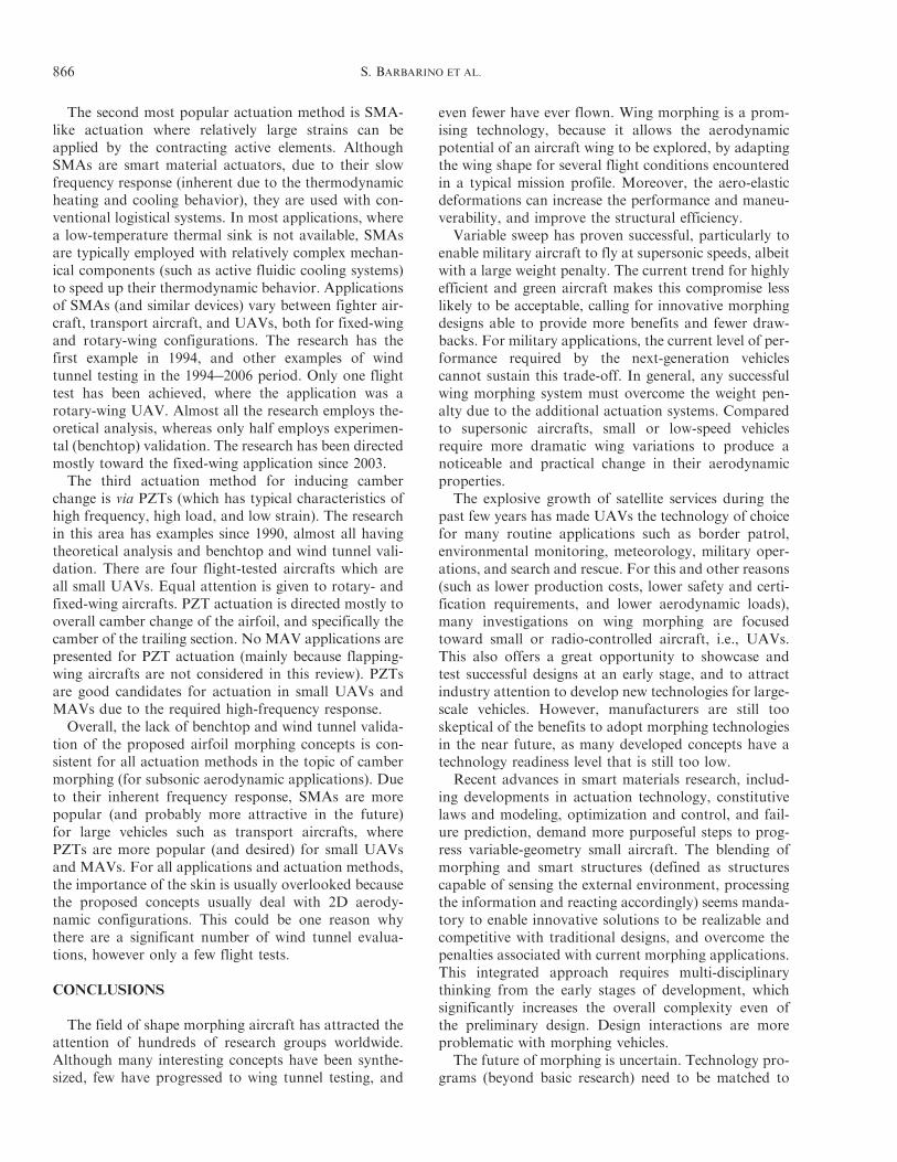
The second most popular actuation method is SMA-like actuation where relatively large strains can beapplied by the contracting active elements. AlthoughSMAs are smart material actuators, due to their slowfrequency response (inherent due to the thermodynamicheating and cooling behavior), they are used with con-ventional logistical systems. In most applications, wherea low-temperature thermal sink is not available, SMAsare typically employed with relatively complex mechan-ical components (such as active fluidic cooling systems)to speed up their thermodynamic behavior. Applicationsof SMAs (and similar devices) vary between fighter air-craft, transport aircraft, and UAVs, both for fixed-wingand rotary-wing configurations. The research has thefirst example in 1994, and other examples of windtunnel testing in the 1994!2006 period. Only one flighttest has been achieved, where the application was arotary-wing UAV. Almost all the research employs the-oretical analysis, whereas only half employs experimen-tal (benchtop) validation. The research has been directedmostly toward the fixed-wing application since 2003.The third actuation method for inducing camber
change is via PZTs (which has typical characteristics ofhigh frequency, high load, and low strain). The researchin this area has examples since 1990, almost all havingtheoretical analysis and benchtop and wind tunnel vali-dation. There are four flight-tested aircrafts which areall small UAVs. Equal attention is given to rotary- andfixed-wing aircrafts. PZT actuation is directed mostly tooverall camber change of the airfoil, and specifically thecamber of the trailing section. No MAV applications arepresented for PZT actuation (mainly because flapping-wing aircrafts are not considered in this review). PZTsare good candidates for actuation in small UAVs andMAVs due to the required high-frequency response.Overall, the lack of benchtop and wind tunnel valida-
tion of the proposed airfoil morphing concepts is con-sistent for all actuation methods in the topic of cambermorphing (for subsonic aerodynamic applications). Dueto their inherent frequency response, SMAs are morepopular (and probably more attractive in the future)for large vehicles such as transport aircrafts, wherePZTs are more popular (and desired) for small UAVsand MAVs. For all applications and actuation methods,the importance of the skin is usually overlooked becausethe proposed concepts usually deal with 2D aerody-namic configurations. This could be one reason whythere are a significant number of wind tunnel evalua-tions, however only a few flight tests.
CONCLUSIONS
The field of shape morphing aircraft has attracted theattention of hundreds of research groups worldwide.Although many interesting concepts have been synthe-sized, few have progressed to wing tunnel testing, and
even fewer have ever flown. Wing morphing is a prom-ising technology, because it allows the aerodynamicpotential of an aircraft wing to be explored, by adaptingthe wing shape for several flight conditions encounteredin a typical mission profile. Moreover, the aero-elasticdeformations can increase the performance and maneu-verability, and improve the structural efficiency.
Variable sweep has proven successful, particularly toenable military aircraft to fly at supersonic speeds, albeitwith a large weight penalty. The current trend for highlyefficient and green aircraft makes this compromise lesslikely to be acceptable, calling for innovative morphingdesigns able to provide more benefits and fewer draw-backs. For military applications, the current level of per-formance required by the next-generation vehiclescannot sustain this trade-off. In general, any successfulwing morphing system must overcome the weight pen-alty due to the additional actuation systems. Comparedto supersonic aircrafts, small or low-speed vehiclesrequire more dramatic wing variations to produce anoticeable and practical change in their aerodynamicproperties.
The explosive growth of satellite services during thepast few years has made UAVs the technology of choicefor many routine applications such as border patrol,environmental monitoring, meteorology, military oper-ations, and search and rescue. For this and other reasons(such as lower production costs, lower safety and certi-fication requirements, and lower aerodynamic loads),many investigations on wing morphing are focusedtoward small or radio-controlled aircraft, i.e., UAVs.This also offers a great opportunity to showcase andtest successful designs at an early stage, and to attractindustry attention to develop new technologies for large-scale vehicles. However, manufacturers are still tooskeptical of the benefits to adopt morphing technologiesin the near future, as many developed concepts have atechnology readiness level that is still too low.
Recent advances in smart materials research, includ-ing developments in actuation technology, constitutivelaws and modeling, optimization and control, and fail-ure prediction, demand more purposeful steps to prog-ress variable-geometry small aircraft. The blending ofmorphing and smart structures (defined as structurescapable of sensing the external environment, processingthe information and reacting accordingly) seems manda-tory to enable innovative solutions to be realizable andcompetitive with traditional designs, and overcome thepenalties associated with current morphing applications.This integrated approach requires multi-disciplinarythinking from the early stages of development, whichsignificantly increases the overall complexity even ofthe preliminary design. Design interactions are moreproblematic with morphing vehicles.
The future of morphing is uncertain. Technology pro-grams (beyond basic research) need to be matched to
866 S. BARBARINO ET AL.
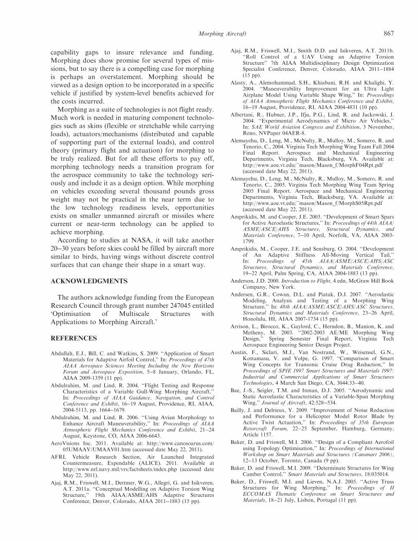
capability gaps to insure relevance and funding.Morphing does show promise for several types of mis-sions, but to say there is a compelling case for morphingis perhaps an overstatement. Morphing should beviewed as a design option to be incorporated in a specificvehicle if justified by system-level benefits achieved forthe costs incurred.Morphing as a suite of technologies is not flight ready.
Much work is needed in maturing component technolo-gies such as skins (flexible or stretchable while carryingloads), actuators/mechanisms (distributed and capableof supporting part of the external loads), and controltheory (primary flight and actuation) for morphing tobe truly realized. But for all these efforts to pay off,morphing technology needs a transition program forthe aerospace community to take the technology seri-ously and include it as a design option. While morphingon vehicles exceeding several thousand pounds grossweight may not be practical in the near term due tothe low technology readiness levels, opportunitiesexists on smaller unmanned aircraft or missiles wherecurrent or near-term technology can be applied toachieve morphing.According to studies at NASA, it will take another
20!30 years before skies could be filled by aircraft moresimilar to birds, having wings without discrete controlsurfaces that can change their shape in a smart way.
ACKNOWLEDGMENTS
The authors acknowledge funding from the EuropeanResearch Council through grant number 247045 entitled‘Optimisation of Multiscale Structures withApplications to Morphing Aircraft.’
REFERENCES
Abdullah, E.J., Bill, C. and Watkins, S. 2009. ‘‘Application of SmartMaterials for Adaptive Airfoil Control,’’ In: Proceedings of 47thAIAA Aerospace Sciences Meeting Including the New HorizonsForum and Aerospace Exposition, 5!8 January, Orlando, FL,AIAA 2009-1359 (11 pp).
Abdulrahim, M. and Lind, R. 2004. ‘‘Flight Testing and ResponseCharacteristics of a Variable Gull-Wing Morphing Aircraft,’’In: Proceedings of AIAA Guidance, Navigation, and ControlConference and Exhibit, 16!19 August, Providence, RI, AIAA,2004-5113, pp. 1664!1679.
Abdulrahim, M. and Lind, R. 2006. ‘‘Using Avian Morphology toEnhance Aircraft Maneuverability,’’ In: Proceedings of AIAAAtmospheric Flight Mechanics Conference and Exhibit, 21!24August, Keystone, CO, AIAA 2006-6643.
AeroVisions Inc. 2011. Available at: http://www.canosoarus.com/05UMAAV/UMAAV01.htm (accessed date May 22, 2011).
AFRL Vehicle Research Section, Air Launched IntegratedCountermeasure, Expendable (ALICE). 2011. Available athttp://www.nrl.navy.mil/vrs/factsheets/index.php (accessed dateMay 22, 2011).
Ajaj, R.M., Friswell, M.I., Dettmer, W.G., Allegri, G. and Isikveren,A.T. 2011a. ‘‘Conceptual Modelling on Adaptive Torsion WingStructure,’’ 19th AIAA/ASME/AHS Adaptive StructuresConference, Denver, Colorado, AIAA 2011!1883 (15 pp).
Ajaj, R.M., Friswell, M.I., Smith D.D. and Isikveren, A.T. 2011b.‘‘Roll Control of a UAV Using an Adaptive TorsionStructure’’ 7th AIAA Multidisciplinary Design OptimizationSpecialist Conference, Denver, Colorado, AIAA 2011!1884(15 pp).
Alasty, A., Alemohammad, S.H., Khiabani, R.H. and Khalighi, Y.2004. ‘‘Maneuverability Improvement for an Ultra LightAirplane Model Using Variable Shape Wing,’’ In: Proceedingsof AIAA Atmospheric Flight Mechanics Conference and Exhibit,16!19 August, Providence, RI, AIAA 2004-4831 (10 pp).
Albertani, R., Hubner, J.P., Ifju, P.G., Lind, R. and Jackowski, J.2004. ‘‘Experimental Aerodynamics of Micro Air Vehicles,’’In: SAE World Aviation Congress and Exhibition, 3 November,Reno, NVPaper 04AER-8.
Alemayehu, D., Leng, M., McNulty, R., Mulloy, M., Somero, R. andTenorio, C., 2004. Virginia Tech Morphing Wing Team Fall 2004Final Report. Aerospace and Mechanical EngineeringDepartments, Virginia Tech, Blacksburg, VA. Available at:http://www.aoe.vt.edu/~mason/Mason_f/MorphF04Rpt.pdf(accessed date May 22, 2011).
Alemayehu, D., Leng, M., McNulty, R., Mulloy, M., Somero, R. andTenorio, C., 2005. Virginia Tech Morphing Wing Team Spring2005 Final Report. Aerospace and Mechanical EngineeringDepartments, Virginia Tech, Blacksburg, VA. Available at:http://www.aoe.vt.edu/~mason/Mason_f/MorphS05Rpt.pdf(accessed date May 22, 2011).
Amprikidis, M. and Cooper, J.E. 2003. ‘‘Development of Smart Sparsfor Active Aeroelastic Structures,’’ In: Proceedings of 44th AIAA/ASME/ASCE/AHS Structures, Structural Dynamics, andMaterials Conference, 7!10 April, Norfolk, VA, AIAA 2003-1799.
Amprikidis, M., Cooper, J.E. and Sensburg, O. 2004. ‘‘Developmentof An Adaptive Stiffness All-Moving Vertical Tail,’’In: Proceedings of 45th AIAA/ASME/ASCE/AHS/ASCStructures, Structural Dynamics, and Materials Conference,19!22 April, Palm Spring, CA, AIAA 2004-1883 (13 pp).
Anderson, J.D. 2000. Introduction to Flight, 4 edn, McGraw Hill BookCompany, New York.
Andersen, G.R., Cowan, D.L. and Piatak, D.J. 2007. ‘‘AeroelasticModeling, Analysis and Testing of a Morphing WingStructure,’’ In: 48th AIAA/ASME/ASCE/AHS/ASC Structures,Structural Dynamics and Materials Conference, 23!26 April,Honolulu, HI, AIAA 2007-1734 (15 pp).
Arrison, L., Birocco, K., Gaylord, C., Herndon, B., Manion, K. andMetheny, M. 2003. ‘‘2002-2003 AE/ME Morphing WingDesign,’’ Spring Semester Final Report, Virginia TechAerospace Engineering Senior Design Project.
Austin, F., Siclari, M.J., Van Nostrand, W., Weisensel, G.N.,Kottamasu, V. and Volpe, G. 1997. ‘‘Comparison of SmartWing Concepts for Transonic Cruise Drag Reduction,’’ InProceedings of SPIE 1997 Smart Structures and Materials 1997:Industrial and Commercial Applications of Smart StructuresTechnologies, 4 March San Diego, CA, 3044:33!40.
Bae, J.-S., Seigler, T.M. and Inman, D.J. 2005. ‘‘Aerodynamic andStatic Aeroelastic Characteristics of a Variable-Span MorphingWing,’’ Journal of Aircraft, 42:528!534.
Bailly, J. and Delrieux, Y. 2009. ‘‘Improvement of Noise Reductionand Performance for a Helicopter Model Rotor Blade byActive Twist Actuation,’’ In: Proceedings of 35th EuropeanRotorcraft Forum, 22!25 September, Hamburg, Germany,Article 1157.
Baker, D. and Friswell, M.I. 2006. ‘‘Design of a Compliant Aerofoilusing Topology Optimisation,’’ In: Proceedings of InternationalWorkshop on Smart Materials and Structures (Cansmart 2006),12!13 October, Toronto, Canada (9 pp).
Baker, D. and Friswell, M.I. 2009. ‘‘Determinate Structures for WingCamber Control,’’ Smart Materials and Structures, 18:035014.
Baker, D., Friswell, M.I. and Lieven, N.A.J. 2005. ‘‘Active TrussStructures for Wing Morphing,’’ In: Proceedings of IIECCOMAS Thematic Conference on Smart Structures andMaterials, 18!21 July, Lisbon, Portugal (11 pp).
Morphing Aircraft 867
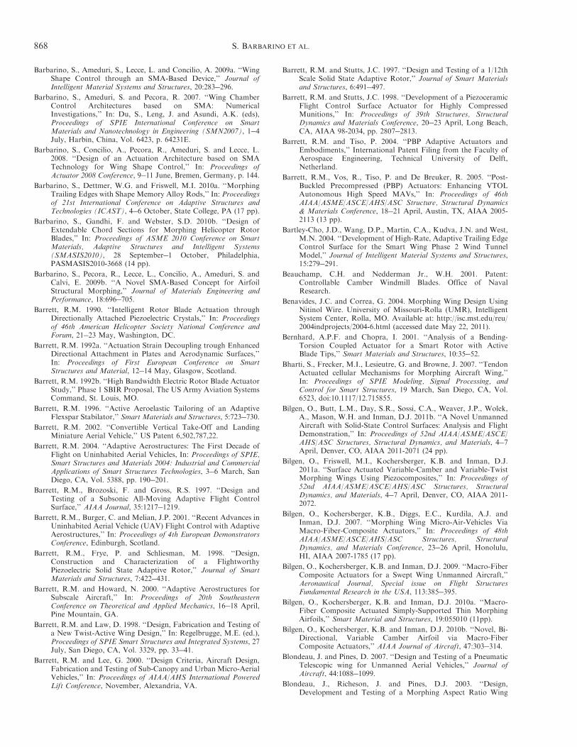
Barbarino, S., Ameduri, S., Lecce, L. and Concilio, A. 2009a. ‘‘WingShape Control through an SMA-Based Device,’’ Journal ofIntelligent Material Systems and Structures, 20:283!296.
Barbarino, S., Ameduri, S. and Pecora, R. 2007. ‘‘Wing ChamberControl Architectures based on SMA: NumericalInvestigations,’’ In: Du, S., Leng, J. and Asundi, A.K. (eds),Proceedings of SPIE International Conference on SmartMaterials and Nanotechnology in Engineering (SMN2007), 1!4July, Harbin, China, Vol. 6423, p. 64231E.
Barbarino, S., Concilio, A., Pecora, R., Ameduri, S. and Lecce, L.2008. ‘‘Design of an Actuation Architecture based on SMATechnology for Wing Shape Control,’’ In: Proceedings ofActuator 2008 Conference, 9!11 June, Bremen, Germany, p. 144.
Barbarino, S., Dettmer, W.G. and Friswell, M.I. 2010a. ‘‘MorphingTrailing Edges with Shape Memory Alloy Rods,’’ In: Proceedingsof 21st International Conference on Adaptive Structures andTechnologies (ICAST), 4!6 October, State College, PA (17 pp).
Barbarino, S., Gandhi, F. and Webster, S.D. 2010b. ‘‘Design ofExtendable Chord Sections for Morphing Helicopter RotorBlades,’’ In: Proceedings of ASME 2010 Conference on SmartMaterials, Adaptive Structures and Intelligent Systems(SMASIS2010), 28 September!1 October, Philadelphia,PASMASIS2010-3668 (14 pp).
Barbarino, S., Pecora, R., Lecce, L., Concilio, A., Ameduri, S. andCalvi, E. 2009b. ‘‘A Novel SMA-Based Concept for AirfoilStructural Morphing,’’ Journal of Materials Engineering andPerformance, 18:696!705.
Barrett, R.M. 1990. ‘‘Intelligent Rotor Blade Actuation throughDirectionally Attached Piezoelectric Crystals,’’ In: Proceedingsof 46th American Helicopter Society National Conference andForum, 21!23 May, Washington, DC.
Barrett, R.M. 1992a. ‘‘Actuation Strain Decoupling trough EnhancedDirectional Attachment in Plates and Aerodynamic Surfaces,’’In: Proceedings of First European Conference on SmartStructures and Material, 12!14 May, Glasgow, Scotland.
Barrett, R.M. 1992b. ‘‘High Bandwidth Electric Rotor Blade ActuatorStudy,’’ Phase 1 SBIR Proposal, The US Army Aviation SystemsCommand, St. Louis, MO.
Barrett, R.M. 1996. ‘‘Active Aeroelastic Tailoring of an AdaptiveFlexspar Stabilator,’’ Smart Materials and Structures, 5:723!730.
Barrett, R.M. 2002. ‘‘Convertible Vertical Take-Off and LandingMiniature Aerial Vehicle,’’ US Patent 6,502,787,22.
Barrett, R.M. 2004. ‘‘Adaptive Aerostructures: The First Decade ofFlight on Uninhabited Aerial Vehicles, In: Proceedings of SPIE,Smart Structures and Materials 2004: Industrial and CommercialApplications of Smart Structures Technologies, 3!6 March, SanDiego, CA, Vol. 5388, pp. 190!201.
Barrett, R.M., Brozoski, F. and Gross, R.S. 1997. ‘‘Design andTesting of a Subsonic All-Moving Adaptive Flight ControlSurface,’’ AIAA Journal, 35:1217!1219.
Barrett, R.M., Burger, C. and Melian, J.P. 2001. ‘‘Recent Advances inUninhabited Aerial Vehicle (UAV) Flight Control with AdaptiveAerostructures,’’ In: Proceedings of 4th European DemonstratorsConference, Edinburgh, Scotland.
Barrett, R.M., Frye, P. and Schliesman, M. 1998. ‘‘Design,Construction and Characterization of a FlightworthyPiezoelectric Solid State Adaptive Rotor,’’ Journal of SmartMaterials and Structures, 7:422!431.
Barrett, R.M. and Howard, N. 2000. ‘‘Adaptive Aerostructures forSubscale Aircraft,’’ In: Proceedings of 20th SoutheasternConference on Theoretical and Applied Mechanics, 16!18 April,Pine Mountain, GA.
Barrett, R.M. and Law, D. 1998. ‘‘Design, Fabrication and Testing ofa New Twist-Active Wing Design,’’ In: Regelbrugge, M.E. (ed.),Proceedings of SPIE Smart Structures and Integrated Systems, 27July, San Diego, CA, Vol. 3329, pp. 33!41.
Barrett, R.M. and Lee, G. 2000. ‘‘Design Criteria, Aircraft Design,Fabrication and Testing of Sub-Canopy and Urban Micro-AerialVehicles,’’ In: Proceedings of AIAA/AHS International PoweredLift Conference, November, Alexandria, VA.
Barrett, R.M. and Stutts, J.C. 1997. ‘‘Design and Testing of a 1/12thScale Solid State Adaptive Rotor,’’ Journal of Smart Materialsand Structures, 6:491!497.
Barrett, R.M. and Stutts, J.C. 1998. ‘‘Development of a PiezoceramicFlight Control Surface Actuator for Highly CompressedMunitions,’’ In: Proceedings of 39th Structures, StructuralDynamics and Materials Conference, 20!23 April, Long Beach,CA, AIAA 98-2034, pp. 2807!2813.
Barrett, R.M. and Tiso, P. 2004. ‘‘PBP Adaptive Actuators andEmbodiments,’’ International Patent Filing from the Faculty ofAerospace Engineering, Technical University of Delft,Netherland.
Barrett, R.M., Vos, R., Tiso, P. and De Breuker, R. 2005. ‘‘Post-Buckled Precompressed (PBP) Actuators: Enhancing VTOLAutonomous High Speed MAVs,’’ In: Proceedings of 46thAIAA/ASME/ASCE/AHS/ASC Structure, Structural Dynamics& Materials Conference, 18!21 April, Austin, TX, AIAA 2005-2113 (13 pp).
Bartley-Cho, J.D., Wang, D.P., Martin, C.A., Kudva, J.N. and West,M.N. 2004. ‘‘Development of High-Rate, Adaptive Trailing EdgeControl Surface for the Smart Wing Phase 2 Wind TunnelModel,’’ Journal of Intelligent Material Systems and Structures,15:279!291.
Beauchamp, C.H. and Nedderman Jr., W.H. 2001. Patent:Controllable Camber Windmill Blades. Office of NavalResearch.
Benavides, J.C. and Correa, G. 2004. Morphing Wing Design UsingNitinol Wire. University of Missouri-Rolla (UMR), IntelligentSystem Center, Rolla, MO. Available at: http://isc.mst.edu/reu/2004indprojects/2004-6.html (accessed date May 22, 2011).
Bernhard, A.P.F. and Chopra, I. 2001. ‘‘Analysis of a Bending-Torsion Coupled Actuator for a Smart Rotor with ActiveBlade Tips,’’ Smart Materials and Structures, 10:35!52.
Bharti, S., Frecker, M.I., Lesieutre, G. and Browne, J. 2007. ‘‘TendonActuated cellular Mechanisms for Morphing Aircraft Wing,’’In: Proceedings of SPIE Modeling, Signal Processing, andControl for Smart Structures, 19 March, San Diego, CA, Vol.6523, doi:10.1117/12.715855.
Bilgen, O., Butt, L.M., Day, S.R., Sossi, C.A., Weaver, J.P., Wolek,A., Mason, W.H. and Inman, D.J. 2011b. ‘‘A Novel UnmannedAircraft with Solid-State Control Surfaces: Analysis and FlightDemonstration,’’ In: Proceedings of 52nd AIAA/ASME/ASCE/AHS/ASC Structures, Structural Dynamics, and Materials, 4!7April, Denver, CO, AIAA 2011-2071 (24 pp).
Bilgen, O., Friswell, M.I., Kochersberger, K.B. and Inman, D.J.2011a. ‘‘Surface Actuated Variable-Camber and Variable-TwistMorphing Wings Using Piezocomposites,’’ In: Proceedings of52nd AIAA/ASME/ASCE/AHS/ASC Structures, StructuralDynamics, and Materials, 4!7 April, Denver, CO, AIAA 2011-2072.
Bilgen, O., Kochersberger, K.B., Diggs, E.C., Kurdila, A.J. andInman, D.J. 2007. ‘‘Morphing Wing Micro-Air-Vehicles ViaMacro-Fiber-Composite Actuators,’’ In: Proceedings of 48thAIAA/ASME/ASCE/AHS/ASC Structures, StructuralDynamics, and Materials Conference, 23!26 April, Honolulu,HI, AIAA 2007-1785 (17 pp).
Bilgen, O., Kochersberger, K.B. and Inman, D.J. 2009. ‘‘Macro-FiberComposite Actuators for a Swept Wing Unmanned Aircraft,’’Aeronautical Journal, Special issue on Flight StructuresFundamental Research in the USA, 113:385!395.
Bilgen, O., Kochersberger, K.B. and Inman, D.J. 2010a. ‘‘Macro-Fiber Composite Actuated Simply-Supported Thin MorphingAirfoils,’’ Smart Material and Structures, 19:055010 (11pp).
Bilgen, O., Kochersberger, K.B. and Inman, D.J. 2010b. ‘‘Novel, Bi-Directional, Variable Camber Airfoil via Macro-FiberComposite Actuators,’’ AIAA Journal of Aircraft, 47:303!314.
Blondeau, J. and Pines, D. 2007. ‘‘Design and Testing of a PneumaticTelescopic wing for Unmanned Aerial Vehicles,’’ Journal ofAircraft, 44:1088!1099.
Blondeau, J., Richeson, J. and Pines, D.J. 2003. ‘‘Design,Development and Testing of a Morphing Aspect Ratio Wing
868 S. BARBARINO ET AL.
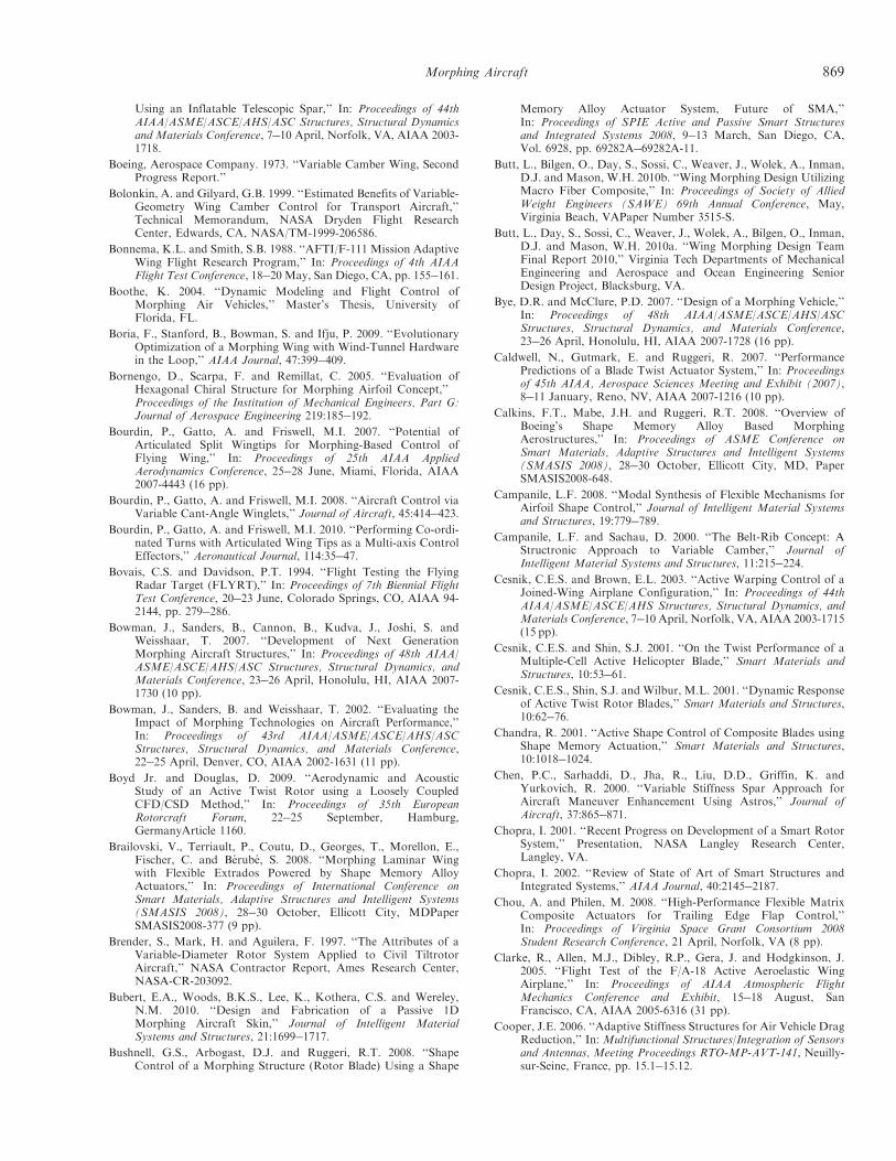
Using an Inflatable Telescopic Spar,’’ In: Proceedings of 44thAIAA/ASME/ASCE/AHS/ASC Structures, Structural Dynamicsand Materials Conference, 7!10 April, Norfolk, VA, AIAA 2003-1718.
Boeing, Aerospace Company. 1973. ‘‘Variable Camber Wing, SecondProgress Report.’’
Bolonkin, A. and Gilyard, G.B. 1999. ‘‘Estimated Benefits of Variable-Geometry Wing Camber Control for Transport Aircraft,’’Technical Memorandum, NASA Dryden Flight ResearchCenter, Edwards, CA, NASA/TM-1999-206586.
Bonnema, K.L. and Smith, S.B. 1988. ‘‘AFTI/F-111 Mission AdaptiveWing Flight Research Program,’’ In: Proceedings of 4th AIAAFlight Test Conference, 18!20 May, San Diego, CA, pp. 155!161.
Boothe, K. 2004. ‘‘Dynamic Modeling and Flight Control ofMorphing Air Vehicles,’’ Master’s Thesis, University ofFlorida, FL.
Boria, F., Stanford, B., Bowman, S. and Ifju, P. 2009. ‘‘EvolutionaryOptimization of a Morphing Wing with Wind-Tunnel Hardwarein the Loop,’’ AIAA Journal, 47:399!409.
Bornengo, D., Scarpa, F. and Remillat, C. 2005. ‘‘Evaluation ofHexagonal Chiral Structure for Morphing Airfoil Concept,’’Proceedings of the Institution of Mechanical Engineers, Part G:Journal of Aerospace Engineering 219:185!192.
Bourdin, P., Gatto, A. and Friswell, M.I. 2007. ‘‘Potential ofArticulated Split Wingtips for Morphing-Based Control ofFlying Wing,’’ In: Proceedings of 25th AIAA AppliedAerodynamics Conference, 25!28 June, Miami, Florida, AIAA2007-4443 (16 pp).
Bourdin, P., Gatto, A. and Friswell, M.I. 2008. ‘‘Aircraft Control viaVariable Cant-Angle Winglets,’’ Journal of Aircraft, 45:414!423.
Bourdin, P., Gatto, A. and Friswell, M.I. 2010. ‘‘Performing Co-ordi-nated Turns with Articulated Wing Tips as a Multi-axis ControlEffectors,’’ Aeronautical Journal, 114:35!47.
Bovais, C.S. and Davidson, P.T. 1994. ‘‘Flight Testing the FlyingRadar Target (FLYRT),’’ In: Proceedings of 7th Biennial FlightTest Conference, 20!23 June, Colorado Springs, CO, AIAA 94-2144, pp. 279!286.
Bowman, J., Sanders, B., Cannon, B., Kudva, J., Joshi, S. andWeisshaar, T. 2007. ‘‘Development of Next GenerationMorphing Aircraft Structures,’’ In: Proceedings of 48th AIAA/ASME/ASCE/AHS/ASC Structures, Structural Dynamics, andMaterials Conference, 23!26 April, Honolulu, HI, AIAA 2007-1730 (10 pp).
Bowman, J., Sanders, B. and Weisshaar, T. 2002. ‘‘Evaluating theImpact of Morphing Technologies on Aircraft Performance,’’In: Proceedings of 43rd AIAA/ASME/ASCE/AHS/ASCStructures, Structural Dynamics, and Materials Conference,22!25 April, Denver, CO, AIAA 2002-1631 (11 pp).
Boyd Jr. and Douglas, D. 2009. ‘‘Aerodynamic and AcousticStudy of an Active Twist Rotor using a Loosely CoupledCFD/CSD Method,’’ In: Proceedings of 35th EuropeanRotorcraft Forum, 22!25 September, Hamburg,GermanyArticle 1160.
Brailovski, V., Terriault, P., Coutu, D., Georges, T., Morellon, E.,Fischer, C. and Berube, S. 2008. ‘‘Morphing Laminar Wingwith Flexible Extrados Powered by Shape Memory AlloyActuators,’’ In: Proceedings of International Conference onSmart Materials, Adaptive Structures and Intelligent Systems(SMASIS 2008), 28!30 October, Ellicott City, MDPaperSMASIS2008-377 (9 pp).
Brender, S., Mark, H. and Aguilera, F. 1997. ‘‘The Attributes of aVariable-Diameter Rotor System Applied to Civil TiltrotorAircraft,’’ NASA Contractor Report, Ames Research Center,NASA-CR-203092.
Bubert, E.A., Woods, B.K.S., Lee, K., Kothera, C.S. and Wereley,N.M. 2010. ‘‘Design and Fabrication of a Passive 1DMorphing Aircraft Skin,’’ Journal of Intelligent MaterialSystems and Structures, 21:1699!1717.
Bushnell, G.S., Arbogast, D.J. and Ruggeri, R.T. 2008. ‘‘ShapeControl of a Morphing Structure (Rotor Blade) Using a Shape
Memory Alloy Actuator System, Future of SMA,’’In: Proceedings of SPIE Active and Passive Smart Structuresand Integrated Systems 2008, 9!13 March, San Diego, CA,Vol. 6928, pp. 69282A!69282A-11.
Butt, L., Bilgen, O., Day, S., Sossi, C., Weaver, J., Wolek, A., Inman,D.J. and Mason, W.H. 2010b. ‘‘Wing Morphing Design UtilizingMacro Fiber Composite,’’ In: Proceedings of Society of AlliedWeight Engineers (SAWE) 69th Annual Conference, May,Virginia Beach, VAPaper Number 3515-S.
Butt, L., Day, S., Sossi, C., Weaver, J., Wolek, A., Bilgen, O., Inman,D.J. and Mason, W.H. 2010a. ‘‘Wing Morphing Design TeamFinal Report 2010,’’ Virginia Tech Departments of MechanicalEngineering and Aerospace and Ocean Engineering SeniorDesign Project, Blacksburg, VA.
Bye, D.R. and McClure, P.D. 2007. ‘‘Design of a Morphing Vehicle,’’In: Proceedings of 48th AIAA/ASME/ASCE/AHS/ASCStructures, Structural Dynamics, and Materials Conference,23!26 April, Honolulu, HI, AIAA 2007-1728 (16 pp).
Caldwell, N., Gutmark, E. and Ruggeri, R. 2007. ‘‘PerformancePredictions of a Blade Twist Actuator System,’’ In: Proceedingsof 45th AIAA, Aerospace Sciences Meeting and Exhibit (2007),8!11 January, Reno, NV, AIAA 2007-1216 (10 pp).
Calkins, F.T., Mabe, J.H. and Ruggeri, R.T. 2008. ‘‘Overview ofBoeing’s Shape Memory Alloy Based MorphingAerostructures,’’ In: Proceedings of ASME Conference onSmart Materials, Adaptive Structures and Intelligent Systems(SMASIS 2008), 28!30 October, Ellicott City, MD, PaperSMASIS2008-648.
Campanile, L.F. 2008. ‘‘Modal Synthesis of Flexible Mechanisms forAirfoil Shape Control,’’ Journal of Intelligent Material Systemsand Structures, 19:779!789.
Campanile, L.F. and Sachau, D. 2000. ‘‘The Belt-Rib Concept: AStructronic Approach to Variable Camber,’’ Journal ofIntelligent Material Systems and Structures, 11:215!224.
Cesnik, C.E.S. and Brown, E.L. 2003. ‘‘Active Warping Control of aJoined-Wing Airplane Configuration,’’ In: Proceedings of 44thAIAA/ASME/ASCE/AHS Structures, Structural Dynamics, andMaterials Conference, 7!10 April, Norfolk, VA, AIAA 2003-1715(15 pp).
Cesnik, C.E.S. and Shin, S.J. 2001. ‘‘On the Twist Performance of aMultiple-Cell Active Helicopter Blade,’’ Smart Materials andStructures, 10:53!61.
Cesnik, C.E.S., Shin, S.J. and Wilbur, M.L. 2001. ‘‘Dynamic Responseof Active Twist Rotor Blades,’’ Smart Materials and Structures,10:62!76.
Chandra, R. 2001. ‘‘Active Shape Control of Composite Blades usingShape Memory Actuation,’’ Smart Materials and Structures,10:1018!1024.
Chen, P.C., Sarhaddi, D., Jha, R., Liu, D.D., Griffin, K. andYurkovich, R. 2000. ‘‘Variable Stiffness Spar Approach forAircraft Maneuver Enhancement Using Astros,’’ Journal ofAircraft, 37:865!871.
Chopra, I. 2001. ‘‘Recent Progress on Development of a Smart RotorSystem,’’ Presentation, NASA Langley Research Center,Langley, VA.
Chopra, I. 2002. ‘‘Review of State of Art of Smart Structures andIntegrated Systems,’’ AIAA Journal, 40:2145!2187.
Chou, A. and Philen, M. 2008. ‘‘High-Performance Flexible MatrixComposite Actuators for Trailing Edge Flap Control,’’In: Proceedings of Virginia Space Grant Consortium 2008Student Research Conference, 21 April, Norfolk, VA (8 pp).
Clarke, R., Allen, M.J., Dibley, R.P., Gera, J. and Hodgkinson, J.2005. ‘‘Flight Test of the F/A-18 Active Aeroelastic WingAirplane,’’ In: Proceedings of AIAA Atmospheric FlightMechanics Conference and Exhibit, 15!18 August, SanFrancisco, CA, AIAA 2005-6316 (31 pp).
Cooper, J.E. 2006. ‘‘Adaptive Stiffness Structures for Air Vehicle DragReduction,’’ In: Multifunctional Structures/Integration of Sensorsand Antennas, Meeting Proceedings RTO-MP-AVT-141, Neuilly-sur-Seine, France, pp. 15.1!15.12.
Morphing Aircraft 869
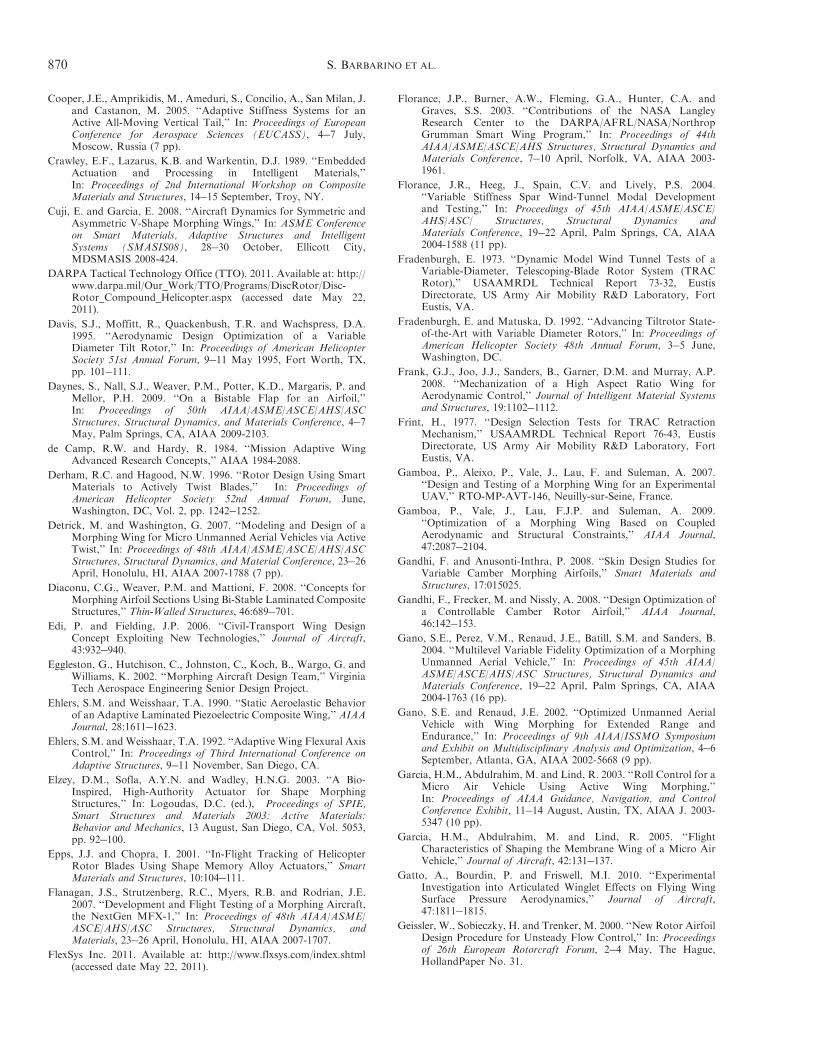
Cooper, J.E., Amprikidis, M., Ameduri, S., Concilio, A., San Milan, J.and Castanon, M. 2005. ‘‘Adaptive Stiffness Systems for anActive All-Moving Vertical Tail,’’ In: Proceedings of EuropeanConference for Aerospace Sciences (EUCASS), 4!7 July,Moscow, Russia (7 pp).
Crawley, E.F., Lazarus, K.B. and Warkentin, D.J. 1989. ‘‘EmbeddedActuation and Processing in Intelligent Materials,’’In: Proceedings of 2nd International Workshop on CompositeMaterials and Structures, 14!15 September, Troy, NY.
Cuji, E. and Garcia, E. 2008. ‘‘Aircraft Dynamics for Symmetric andAsymmetric V-Shape Morphing Wings,’’ In: ASME Conferenceon Smart Materials, Adaptive Structures and IntelligentSystems (SMASIS08), 28!30 October, Ellicott City,MDSMASIS 2008-424.
DARPA Tactical Technology Office (TTO). 2011. Available at: http://www.darpa.mil/Our_Work/TTO/Programs/DiscRotor/Disc-Rotor_Compound_Helicopter.aspx (accessed date May 22,2011).
Davis, S.J., Moffitt, R., Quackenbush, T.R. and Wachspress, D.A.1995. ‘‘Aerodynamic Design Optimization of a VariableDiameter Tilt Rotor,’’ In: Proceedings of American HelicopterSociety 51st Annual Forum, 9!11 May 1995, Fort Worth, TX,pp. 101!111.
Daynes, S., Nall, S.J., Weaver, P.M., Potter, K.D., Margaris, P. andMellor, P.H. 2009. ‘‘On a Bistable Flap for an Airfoil,’’In: Proceedings of 50th AIAA/ASME/ASCE/AHS/ASCStructures, Structural Dynamics, and Materials Conference, 4!7May, Palm Springs, CA, AIAA 2009-2103.
de Camp, R.W. and Hardy, R. 1984. ‘‘Mission Adaptive WingAdvanced Research Concepts,’’ AIAA 1984-2088.
Derham, R.C. and Hagood, N.W. 1996. ‘‘Rotor Design Using SmartMaterials to Actively Twist Blades,’’ In: Proceedings ofAmerican Helicopter Society 52nd Annual Forum, June,Washington, DC, Vol. 2, pp. 1242!1252.
Detrick, M. and Washington, G. 2007. ‘‘Modeling and Design of aMorphing Wing for Micro Unmanned Aerial Vehicles via ActiveTwist,’’ In: Proceedings of 48th AIAA/ASME/ASCE/AHS/ASCStructures, Structural Dynamics, and Material Conference, 23!26April, Honolulu, HI, AIAA 2007-1788 (7 pp).
Diaconu, C.G., Weaver, P.M. and Mattioni, F. 2008. ‘‘Concepts forMorphing Airfoil Sections Using Bi-Stable Laminated CompositeStructures,’’ Thin-Walled Structures, 46:689!701.
Edi, P. and Fielding, J.P. 2006. ‘‘Civil-Transport Wing DesignConcept Exploiting New Technologies,’’ Journal of Aircraft,43:932!940.
Eggleston, G., Hutchison, C., Johnston, C., Koch, B., Wargo, G. andWilliams, K. 2002. ‘‘Morphing Aircraft Design Team,’’ VirginiaTech Aerospace Engineering Senior Design Project.
Ehlers, S.M. and Weisshaar, T.A. 1990. ‘‘Static Aeroelastic Behaviorof an Adaptive Laminated Piezoelectric Composite Wing,’’ AIAAJournal, 28:1611!1623.
Ehlers, S.M. and Weisshaar, T.A. 1992. ‘‘Adaptive Wing Flexural AxisControl,’’ In: Proceedings of Third International Conference onAdaptive Structures, 9!11 November, San Diego, CA.
Elzey, D.M., Sofla, A.Y.N. and Wadley, H.N.G. 2003. ‘‘A Bio-Inspired, High-Authority Actuator for Shape MorphingStructures,’’ In: Logoudas, D.C. (ed.), Proceedings of SPIE,Smart Structures and Materials 2003: Active Materials:Behavior and Mechanics, 13 August, San Diego, CA, Vol. 5053,pp. 92!100.
Epps, J.J. and Chopra, I. 2001. ‘‘In-Flight Tracking of HelicopterRotor Blades Using Shape Memory Alloy Actuators,’’ SmartMaterials and Structures, 10:104!111.
Flanagan, J.S., Strutzenberg, R.C., Myers, R.B. and Rodrian, J.E.2007. ‘‘Development and Flight Testing of a Morphing Aircraft,the NextGen MFX-1,’’ In: Proceedings of 48th AIAA/ASME/ASCE/AHS/ASC Structures, Structural Dynamics, andMaterials, 23!26 April, Honolulu, HI, AIAA 2007-1707.
FlexSys Inc. 2011. Available at: http://www.flxsys.com/index.shtml(accessed date May 22, 2011).
Florance, J.P., Burner, A.W., Fleming, G.A., Hunter, C.A. andGraves, S.S. 2003. ‘‘Contributions of the NASA LangleyResearch Center to the DARPA/AFRL/NASA/NorthropGrumman Smart Wing Program,’’ In: Proceedings of 44thAIAA/ASME/ASCE/AHS Structures, Structural Dynamics andMaterials Conference, 7!10 April, Norfolk, VA, AIAA 2003-1961.
Florance, J.R., Heeg, J., Spain, C.V. and Lively, P.S. 2004.‘‘Variable Stiffness Spar Wind-Tunnel Modal Developmentand Testing,’’ In: Proceedings of 45th AIAA/ASME/ASCE/AHS/ASC/ Structures, Structural Dynamics andMaterials Conference, 19!22 April, Palm Springs, CA, AIAA2004-1588 (11 pp).
Fradenburgh, E. 1973. ‘‘Dynamic Model Wind Tunnel Tests of aVariable-Diameter, Telescoping-Blade Rotor System (TRACRotor),’’ USAAMRDL Technical Report 73-32, EustisDirectorate, US Army Air Mobility R&D Laboratory, FortEustis, VA.
Fradenburgh, E. and Matuska, D. 1992. ‘‘Advancing Tiltrotor State-of-the-Art with Variable Diameter Rotors,’’ In: Proceedings ofAmerican Helicopter Society 48th Annual Forum, 3!5 June,Washington, DC.
Frank, G.J., Joo, J.J., Sanders, B., Garner, D.M. and Murray, A.P.2008. ‘‘Mechanization of a High Aspect Ratio Wing forAerodynamic Control,’’ Journal of Intelligent Material Systemsand Structures, 19:1102!1112.
Frint, H., 1977. ‘‘Design Selection Tests for TRAC RetractionMechanism,’’ USAAMRDL Technical Report 76-43, EustisDirectorate, US Army Air Mobility R&D Laboratory, FortEustis, VA.
Gamboa, P., Aleixo, P., Vale, J., Lau, F. and Suleman, A. 2007.‘‘Design and Testing of a Morphing Wing for an ExperimentalUAV,’’ RTO-MP-AVT-146, Neuilly-sur-Seine, France.
Gamboa, P., Vale, J., Lau, F.J.P. and Suleman, A. 2009.‘‘Optimization of a Morphing Wing Based on CoupledAerodynamic and Structural Constraints,’’ AIAA Journal,47:2087!2104.
Gandhi, F. and Anusonti-Inthra, P. 2008. ‘‘Skin Design Studies forVariable Camber Morphing Airfoils,’’ Smart Materials andStructures, 17:015025.
Gandhi, F., Frecker, M. and Nissly, A. 2008. ‘‘Design Optimization ofa Controllable Camber Rotor Airfoil,’’ AIAA Journal,46:142!153.
Gano, S.E., Perez, V.M., Renaud, J.E., Batill, S.M. and Sanders, B.2004. ‘‘Multilevel Variable Fidelity Optimization of a MorphingUnmanned Aerial Vehicle,’’ In: Proceedings of 45th AIAA/ASME/ASCE/AHS/ASC Structures, Structural Dynamics andMaterials Conference, 19!22 April, Palm Springs, CA, AIAA2004-1763 (16 pp).
Gano, S.E. and Renaud, J.E. 2002. ‘‘Optimized Unmanned AerialVehicle with Wing Morphing for Extended Range andEndurance,’’ In: Proceedings of 9th AIAA/ISSMO Symposiumand Exhibit on Multidisciplinary Analysis and Optimization, 4!6September, Atlanta, GA, AIAA 2002-5668 (9 pp).
Garcia, H.M., Abdulrahim, M. and Lind, R. 2003. ‘‘Roll Control for aMicro Air Vehicle Using Active Wing Morphing,’’In: Proceedings of AIAA Guidance, Navigation, and ControlConference Exhibit, 11!14 August, Austin, TX, AIAA J. 2003-5347 (10 pp).
Garcia, H.M., Abdulrahim, M. and Lind, R. 2005. ‘‘FlightCharacteristics of Shaping the Membrane Wing of a Micro AirVehicle,’’ Journal of Aircraft, 42:131!137.
Gatto, A., Bourdin, P. and Friswell, M.I. 2010. ‘‘ExperimentalInvestigation into Articulated Winglet Effects on Flying WingSurface Pressure Aerodynamics,’’ Journal of Aircraft,47:1811!1815.
Geissler, W., Sobieczky, H. and Trenker, M. 2000. ‘‘New Rotor AirfoilDesign Procedure for Unsteady Flow Control,’’ In: Proceedingsof 26th European Rotorcraft Forum, 2!4 May, The Hague,HollandPaper No. 31.
870 S. BARBARINO ET AL.
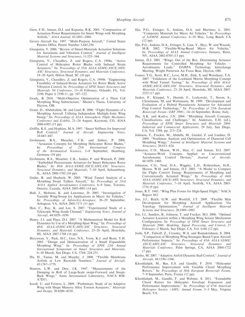
Gern, F.H., Inman, D.J. and Kapania, R.K. 2005. ‘‘Computation ofActuation Power Requirements for Smart Wings with MorphingAirfoils,’’ AIAA Journal, 43:2481!2486.
Gevers Aircraft Inc. 1997. ‘‘Multi-Purpose Aircraft,’’ United StatesPatents Office, Patent Number 5,645,250.
Giurgiutiu, V. 2000. ‘‘Review of Smart-Materials Actuation Solutionsfor Aeroelastic and Vibration Control,’’ Journal of IntelligentMaterial Systems and Structures, 11:525!544.
Giurgiutiu, V., Chaudhry, Z. and Rogers, C.A. 1994a. ‘‘ActiveControl of Helicopter Rotor Blades with Induced StrainActuators,’’ In: Proceedings of 35th AIAA/ASME/ASCE/AHS/ASC Structures, Structural Dynamics, and Materials Conference,18!20 April, Hilton Head, SC (10 pp).
Giurgiutiu, V., Chaudhry, Z. and Rogers, C.A. 1994b. ‘‘EngineeringFeasibility of Induced-Strain Actuators for Rotor Blade ActiveVibration Control, In: Proceedings of SPIE Smart Structures andMaterials ’94 Conference, 13!18 February, Orlando, FL, Vol.2190, Paper # 2190-11, pp. 107!122.
Grady, B. 2010. ‘‘Multi-Objective Optimization of a Three CellMorphing Wing Substructure,’’ Master’s Thesis, University ofDayton, OH.
Grant, D., Abdulrahim, M. and Lind, R. 2006. ‘‘Flight Dynamics of aMorphing Aircraft Utilizing Independent Multiple-Joint WingSweep,’’ In: Proceedings of AIAA Atmospheric Flight MechanicsConference and Exhibit, 21!24 August, Keystone, CO, AIAA2006-6505 (15 pp).
Griffin, K.E. and Hopkins, M.A. 1997. ‘‘Smart Stiffness for ImprovedRoll Control,’’ Journal of Aircraft, Engineering Notes,34:445!447.
Grohmann, B.A., Maucher, C.K. and Janker, P. 2006.‘‘Actuation Concepts for Morphing Helicopter Rotor Blades,’’In: Proceedings of 25th International Congressof the Aeronautical Sciences, 3!8 September, Hamburg,Germany (10 pp).
Grohmann, B.A., Maucher, C.K., Janker, P. and Wierach, P. 2008.‘‘Embedded Piezoceramic Actuators for Smart Helicopter RotorBlades,’’ In: 49th AIAA/ASME/ASCE/AHS/ASC Structures,Structural Dynamics, and Materials, 7!10 April, Schaumburg,IL, AIAA 2008-1702 (10 pp).
Guiler, R. and Huebsch, W. 2005. ‘‘Wind Tunnel Analysis of aMorphing Swept Tailless Aircraft,’’ In: Proceedings of 23rdAIAA Applied Aerodynamics Conference, 6!9 June, Toronto,Ontario, Canada, AIAA 2005-4981 (14 pp).
Hall, J., Mohseni, K. and Lawrence, D. 2005. ‘‘Investigation ofVariable Wing-Sweep for Applications in Micro Air Vehicles,’’In: Proceedings of Infotech@Aerospace, 26!29 September,Arlington, VA, AIAA 2005-7171 (11 pp).
Han, C., Ruy, K. and Lee, S. 2007. ‘‘Experimental Study of aTelescopic Wing Inside Channel,’’ Engineering Notes, Journal ofAircraft, 44:1029!1030.
Henry, J.J. and Pines, D.J. 2007. ‘‘A Mathematical Model for RollDynamics by Use of a Morphing-Span Wing,’’ In: Proceedings of48th AIAA/ASME/ASCE/AHS/ASC Structures, StructuralDynamics, and Materials Conference, 23!26 April, Honolulu,HI, AIAA 2007-1708 (16 pp).
Heryawan, Y., Park, H.C., Goo, N.S., Yoon, K.J. and Byun, Y.H.2005. ‘‘Design and Demonstration of a Small ExpandableMorphing Wing,’’ In: Proceedings of SPIE 12th AnnualInternational Symposium on Smart Structures and Materials,6!10 March, San Diego, CA, 5764: 224-231.
Hu, H., Tamai, M. and Murphy, J. 2008. ‘‘Flexible MembraneAirfoils at Low Reynolds Numbers,’’ Journal of Aircraft,45:1767!1778.
Hunton, L.W. and Dew, J.K. 1947. ‘‘Measurements of theDamping in Roll of Large-Scale swept-Forward and Swept-Back Wings,’’ Ames Aeronautical Laboratory, NACA RM-A7D11.
Icardi, U. and Ferrero, L. 2009. ‘‘Preliminary Study of an AdaptiveWing with Shape Memory Alloy Torsion Actuators,’’ Materialsand Design, 30:4200!4210.
Ifju, P.G., Ettinger, S., Jenkins, D.A. and Martinez, L. 2001.‘‘Composite Materials for Micro Air Vehicles,’’ In: Proceedingsof SAMPE Annual Conference, 6!10 May, Long Beach, CA(12 pp).
Ifju, P.G., Jenkins, D.A., Ettinger, S., Lian, Y., Shyy, W. and Waszak,M.R. 2002. ‘‘Flexible-Wing-Based Micro Air Vehicles,’’In: Proceedings of AIAA Annual Conference, January, Reno,NV, AIAA 2002-0705 (13 pp).
Inman, D.J. 2001. ‘‘Wings: Out of the Box. Determining ActuatorRequirements for Controlled Morphing Air Vehicles !Aerodinamic Loads,’’ DARPA Technology InterchangeMeeting, Wright Patterson Air Force Base, Dayton, OH.
Ivanco, T.G., Scott, R.C., Love, M.H., Zink, S. and Weisshaar, T.A.2007. ‘‘Validation of the Lockheed Martin Morphing Conceptwith Wind Tunnel Testing,’’ In: Proceedings of 48th AIAA/ASME/ASCE/AHS/ASC Structures, Structural Dynamics, andMaterials Conference, 23!26 April, Honolulu, HI, AIAA 2007-2235 (17 pp).
Janker, P., Kloppel, V., Hermle, F., Lorkowski, T., Storm, S.,Christmann, M. and Wettemann, M. 1999. ‘‘Development andEvaluation of a Hybrid Piezoelectric Actuator for AdvancedFlap Control Technology,’’ In: Proceedings of 25th EuropeanRotorcraft Forum (ERF 1999), 14!16 September, Rome, Italy.
Jha, A.K. and Kudva, J.N. 2004. ‘‘Morphing Aircraft Concepts,Classifications, and Challenges,’’ In: Anderson, E.H. (ed.),Proceedings of SPIE Smart Structures and Materials 2004:Industrial and Commercial Applications, 29 July, San Diego,CA, Vol. 5388, pp. 213!224.
Johnson, T., Frecker, M., Abdalla, M., Gurdal, Z. and Lindner, D.2009. ‘‘Nonlinear Analysis and Optimization of Diamond CellMorphing Wings,’’ Journal of Intelligent Material Systems andStructures, 20:815!824.
Johnston, C.O., Mason, W.H., Han, C. and Inman, D.J. 2007.‘‘Actuator-Work Concepts Applied to UnconventionalAerodynamic Control Devices,’’ Journal of Aircraft,44:1459!1468.
Johnston, C.O., Neal, D.A., Wiggins, L.D., Robertshaw, H.H.,Mason, W.H. and Inman, D.J. 2003. ‘‘A Model to Comparethe Flight Control Energy Requirements of Morphing andConventionally Actuated Wings,’’ In: Proceedings of 44thAIAA/ASME/ASCE/AHS Structures, Structural Dynamics, andMaterials Conference, 7!10 April, Norfolk, VA, AIAA 2003-1716 (9 pp).
Jones, R.T. 1945. ‘‘Wing Plan Forms for High-Speed Flight,’’ NACAReport 863.
Joo, J.J., Reich, G.W. and Westfall, J.T. 2009. ‘‘Flexible SkinDevelopment for Morphing Aircraft Applications ViaTopology Optimization,’’ Journal of Intelligent MaterialSystems and Structures, 20:1969!1985.
Joo, J.J., Sanders, B., Johnson, T. and Frecker, M.I. 2006. ‘‘OptimalActuator Location within a Morphing Wing Scissor MechanismConfiguration, In: Proceedings of SPIE Smart Structures andMaterials 2006: Modeling, Signal Processing, and Control, 27February!2 March, San Diego, CA, Vol. 6166 (12 pp).
Joshi, S.P., Tidwell, Z., Crossley, W.A. and Ramakrishnan, S. 2004.‘‘Comparison of Morphing Wing Strategies Based Upon AircraftPerformance Impacts,’’ In: Proceedings of 45th AIAA/ASME/ASCE/AHS/ASC Structures, Structural Dynamics andMaterials Conference, Palm Springs, CA, AIAA 2004-1722(7 pp).
Kerho, M. 2007. ‘‘Adaptive Airfoil Dynamic Stall Control,’’ Journal ofAircraft, 44:1350!1360.
Khoshlahjeh, M., Bae, E.S. and Gandhi, F. 2010. ‘‘HelicopterPerformance Improvement with Variable Chord MorphingRotors,’’ In: Proceedings of 36th European Rotorcraft Forum,7!9 September, Paris, France (12 pp).
Khoshlahjeh, M., Gandhi, F. and Webster, S. 2011. ‘‘ExtendableChord Rotors for Helicopter Envelope Expansion andPerformance Improvement,’’ In: Proceedings of 67th AmericanHelicopter Society (AHS) Annual Forum, 3!5 May, VirginiaBeach, VA.
Morphing Aircraft 871
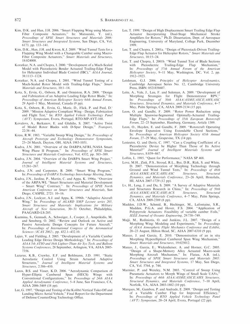
Kim, D.K. and Han, J.H. 2006. ‘‘Smart Flapping Wing using Macro-Fiber Composite Actuators,’’ In: Matsuzaki, Y. (ed.),Proceedings of SPIE Smart Structures and Materials 2006:Smart Structures and Integrated Systems, San Diego, CA, Vol.6173, pp. 133!141.
Kim, D.K., Han, J.H. and Kwon, K.J. 2009. ‘‘Wind Tunnel Tests for aFlapping Wing Model with a Changeable Camber using Macro-Fiber Composite Actuators,’’ Smart Materials and Structures,18:024008.
Koratkar, N.A. and Chopra, I. 2000. ‘‘Development of a Mach-ScaledModel with Piezoelectric Bender Actuated Trailing-Edge Flapsfor Helicopter Individual Blade Control (IBC),’’ AIAA Journal,38:1113!1124.
Koratkar, N.A. and Chopra, I. 2001. ‘‘Wind Tunnel Testing of aMach-Scaled Rotor Model with Trailing-Edge Flaps,’’ SmartMaterials and Structures, 10:1!14.
Kota, S., Ervin, G., Osborn, R. and Ormiston, R.A. 2008. ‘‘Designand Fabrication of an Adaptive Leading Edge Rotor Blade,’’ In:Proceedings of American Helicopter Society 64th Annual Forum,29 April!1 May, Montreal, Canada (9 pp).
Kota, S., Osborn, R., Ervin, G., Maric, D., Flick, P. and Paul, D.‘2009. ‘‘Mission Adaptive Compliant Wing - Design, Fabricationand Flight Test,’’ In: RTO Applied Vehicle Technology Panel(AVT) Symposium, Evora, Portugal, RTO-MP-AVT-168.
Kovalovs, A., Barkanov, E. and Gluhihs, S. 2007. ‘‘Active Twistof Model Rotor Blades with D-Spar Design,’’ Transport,22:38!44.
Kress, R.W. 1983. ‘‘Variable Sweep Wing Design,’’ In: Proceedings ofAircraft Prototype and Technology Demonstrator Symposium,23!24 March, Dayton, OH, AIAA 1983-1051.
Kudva, J.N. 2001. ‘‘Overview of the DARPA/AFRL/NASA SmartWing Phase II Program,’’ In: Proceedings of SPIE SmartStructures and Materials Conference, Vol. 4332, pp. 383!389.
Kudva, J.N. 2004. ‘‘Overview of the DARPA Smart Wing Project,’’Journal of Intelligent Material Systems and Structures,15:261!267.
Kudva, J.N. and Carpenter, B. 2000. ‘‘Smart Wing Program,’’In:Proceedings of DARPATechnology InterchangeMeeting, June.
Kudva, J.N., Jardine, P., Martin, C. and Appa, K. 1996a. ‘‘Overviewof the ARPA/WL ‘‘Smart Structures and Material Development! Smart Wing’’ Contract,’’ In: Proceedings of SPIE NorthAmerican Conference on Smart Structures and Materials, SanDiego, CASPIE, 2721: 10!16.
Kudva, J.N., Lockyer, A.J. and Appa, K. 1996b. ‘‘Adaptive AircraftWing,’’ In: Proceedings of AGARD SMP Lecture series 205,Smart Structures and Materials: Implications for MilitaryAircraft of New Generation, 30!31 October, Philadelphia,PAAGARD-LS-205.
Kuzmina, S., Gennadi, A., Schweiger, J., Cooper, J., Amprikidis, M.and Sensberg, O. 2002. ‘‘Review and Outlook on Active andPassive Aeroelastic Design Concepts for Future Aircraft,’’In: Proceedings of International Congress of the AeronauticalSciences (ICAS 2002), pp. 432.1!432.10.
Lajux, V. and Fielding, J. 2005. ‘‘Development of a Variable CamberLeading Edge Device Design Methodology,’’ In: Proceedings ofAIAA 5th ATIO and 16th Lighter-Than-Air Sys Tech. and BalloonSystems Conferences, 28 September, Arlington, VA, AIAA 2005-7356.
Lazarus, K.B., Crawley, E.F. and Bohlmann, J.D. 1991. ‘‘StaticAeroelastic Control Using Strain Actuated AdaptiveStructures,’’ Journal of Intelligent Material Systems andStructures, 2:386!410.
Lazos, B.S. and Visser, K.D. 2006. ‘‘Aerodynamic Comparison ofHyper-Elliptic Cambered Span (HECS) Wings withConventional Configurations,’’ In: Proceedings of 24th AIAAApplied Aerodynamic Conference, 5!8 June, San Francisco, CA,AIAA 2006-3469 (18 pp).
Lee, G. 1997. ‘‘Design and Testing of the Kolibri Vertical Take-Off andLanding Micro Aerial Vehicle,’’ Final Report for the Departmentof Defense CounterDrug Technology Office.
Lee, T. 1999. ‘‘Design of High Displacement Smart Trailing Edge FlapActuator Incorporating Dual-Stage Mechanical StrokeAmplifiers for Rotors,’’ Ph.D. Dissertation, Dept. of AerospaceEngineering, University of Maryland, College Park, December1999.
Lee, T. and Chopra, I. 2001a. ‘‘Design of Piezostack-Driven Trailing-Edge Flap Actuator for Helicopter Rotors,’’ Smart Materials andStructures, 10:15!24.
Lee, T. and Chopra, I. 2001b. ‘‘Wind Tunnel Test of Blade Sectionswith Piezoelectric Trailing-Edge Flap Mechanism,’’In: Proceedings of 57th Annual Forum of the AmericanHelicopter Society, 9!11 May, Washington, DC, Vol. 2, pp.1912!1923.
Leishman, G.J. 2006. Principles of Helicopter Aerodynamics,Cambridge Aerospace Series No. 12, Cambridge UniversityPress, ISBN: 0521858607.
Leite, A., Vale, J., Lau, F. and Suleman, A. 2009. ‘‘Development ofMorphing Strategies for Flight Demonstrator RPV,’’In: Proceedings of 50th AIAA/ASME/ASCE/AHS/ASCStructures, Structural Dynamics, and Materials Conference, 4!7May, Palm Springs, CA, AIAA 2009-2134 (15 pp).
Leon, O. and Gandhi, F. 2009. ‘‘Rotor Power Reduction usingMultiple Spanwise-Segmented Optimally-Actuated Trailing-Edge Flaps,’’ In: Proceedings of 35th European RotorcraftForum, 22!25 September, Hamburg, Germany, Article 1309.
Leon, O., Hayden, E. and Gandhi, F. 2009. ‘‘Rotorcraft OperatingEnvelope Expansion Using Extendable Chord Sections,’’In: Proceedings of American Helicopter Society 65th AnnualForum, 27!29 May, Grapevine, TX (14 pp).
Lesieutre, G. and Davis, C. 1997. ‘‘Can a Coupling Coefficient of aPiezoelectric Device be Higher Than Those of Its ActiveMaterial?’’ Journal of Intelligent Materials Systems andStructures, 8:859!867.
Loftin, L. 1985. ‘‘Quest for Performance,’’ NASA SP 468.
Love, M.H., Zink, P.S., Stroud, R.L., Bye, D.R., Rizk, S. and White,D. 2007. ‘‘Demonstration of Morphing Technology throughGround and Wind Tunnel Tests,’’ In: Proceedings of 48thAIAA/ASME/ASCE/AHS/ASC Structures, StructuralDynamics, and Materials Conference, 23!26 April, Honolulu,HI, AIAA 2007-1729 (12 pp).
Lv, H., Leng, J. and Du, S. 2009. ‘‘A Survey of Adaptive Materialsand Structures Research in China,’’ In: Proceedings of 50thAIAA/ASME/ASCE/ASH/ACS Structures, StructuralDynamics, and Materials Conference, 4!7 May, Palm Springs,CA, AIAA 2009-2389 (8 pp).
Madden, J.D.W., Schmid, B., Hechinger, M., Lafontaine, S.R.,Madden, P.G.A. and Hover, F.S. 2004. ‘‘Application ofPolypyrrole Actuators: Feasibility of variable camber Foils,’’IEEE Journal of Oceanic Engineering, 29:738!749.
Majji, M., Rediniotis, O. and Junkins, J.L. 2007. ‘‘Design of aMorphing Wing: Modeling and Experiments,’’ In: Proceedingsof AIAA Atmospheric Flight Mechanics Conference and Exhibit,20!23 August, Hilton Head, SC, AIAA 2007-6310 (9 pp).
Manzo, J. and Garcia, E. 2010. ‘‘Demonstration of an in situMorphing Hyperelliptical Cambered Span Wing Mechanism,’’Smart Materials and Structures, 19:025012.
Manzo, J., Garcia, E., Wickenheiser, A. and Horner, G.C. 2005.‘‘Design of a Shape-Memory Alloy Actuated Macro-scaleMorphing Aircraft Mechanism,’’ In: Flatau, A.B. (ed.),Proceedings of SPIE Smart Structures and Materials 2005:Smart Structures and Integrated Systems, 17 May, San Diego,CA, Vol. 5764, p. 744.
Marmier, P. and Wereley, N.M. 2003. ‘‘Control of Sweep UsingPneumatic Actuators to Morph Wings of Small Scale UAVs,’’In: Proceedings of 44th AIAA/ASME/ASCE/AHS Structures,Structural Dynamics, and Materials Conference, 7!10 April,Norfolk, VA, AIAA 2003-1802 (10 pp).
Marques, M., Gamboa, P. and Andrade, E. 2009. ‘‘Design and Testingof a Variable Camber Flap for Improved Efficiency,’’In: Proceedings of RTO Applied Vehicle Technology Panel(AVT) Symposium, 20!24 April, Evora, Portugal (22 pp).
872 S. BARBARINO ET AL.
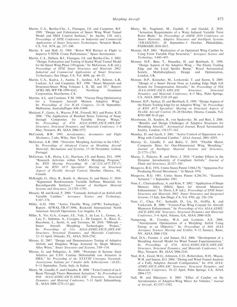
Martin, C.A., Bartley-Cho, J., Flanagan, J.S. and Carpenter, B.F.1999. ‘‘Design and Fabrication of Smart Wing Wind TunnelModel and SMA Control Surfaces,’’ In: Jacobs, J.H. (ed.),Proceedings of SPIE Conference on Industrial and CommercialApplications of Smart Structures Technologies, Newport Beach,CA, Vol. 3674, pp. 237!248.
Martin, S. and Hall, G. 1969. ‘‘Rotor Will Retract in Flight toImprove V/STOL Cruise Performance,’’ Space Aeronautics.
Martin, C.A., Hallam, B.J., Flanagan, J.S. and Bartley-Cho, J. 2002.‘‘Design, Fabrication and Testing of Scaled Wind Tunnel Modelfor the Smart Wing Phase 2 Program,’’ In: McGowan, A.R. (ed.),Proceedings of SPIE Smart Structures and Materials 2002:Industrial and Commercial Applications of Smart StructuresTechnologies, San Diego, CA, Vol. 4698, pp. 44!52.
Martin, C.A., Kudva, J., Austin, F., Jardine, A.P., Scherer, L.B.,Lockyer, A.J. and Carpenter, B.F. 1998. ‘‘Smart Materials andStructures-Smart Wing Volumes I, II, III, and IV,’’ Report:AFRL-ML-WP-TR-1999-4162, Northrop GrummanCorporation, Hawthorne, CA.
Martins, A.L. and Catalano, F.M. 1998. ‘‘Viscous Drag Optimizationfor a Transport Aircraft Mission Adaptive Wing,’’In: Proceedings of 21st ICAS Congress, 13!18 September,Melbourne, AustraliaPaper A98-31499.
Mattioni, F., Gatto, A., Weaver, P.M., Friswell, M.I. and Potter, K.D.2006. ‘‘The Application of Residual Stress Tailoring of Snap-through Composites for Variable Sweep Wings,’’In: Proceedings of 47th AIAA/ASME/ASCE/AHS/ASCStructures, Structural Dynamics, and Materials Conference, 1!4May, Newport, RI, AIAA 2006-1972.
McCormik, B.W. 1995. Aerodynamics, Aeronautics and FlightMechanics, 2 edn, Wiley, New York.
McGowan, A.R. 2008. ‘‘Overview: Morphing Activities in the USA,’’In: Proceedings of Advanced Course on Morphing AircraftMaterials, Mechanisms and Systems, 17!20 November, Lisbon,Portugal.
McGowan, A.R., Horta, L.G., Harrison, J.S. and Raney, D.L. 1999.‘‘Research Activities within NASA’s Morphing Program,’’In: RTO Meeting Proceedings 36 (AC/323(AVT)TP/17)from the RTO AVT Specialists’ Meeting on StructuralAspects of Flexible Aircraft Control, October, Ottawa, AL,Canada.
McKnight, G., Doty, R., Keefe, A., Herrera, G. and Henry, C. 2010.‘‘Segmented Reinforcement Variable Stiffness Materials forReconfigurable Surfaces,’’ Journal of Intelligent MaterialSystems and Structures, 21:1783!1793.
Mesaric, M. and Kosel, F. 2004. ‘‘Unsteady Airload of an Airfoil withVariable Camber,’’ Aerospace Science and Technology,8:167!174.
Miller, G.D. 1988. ‘‘Active Flexible Wing (AFW) Technology,’’Report: AFWAL-TR-87-3096, Rockwell International NorthAmerican Aircraft Operations, Los Angeles, CA.
Miller, S., Vio, G.A., Cooper, J.E., Vale, J., da Luz, L., Gomes, A.,Lau, F., Suleman, A., Cavagna, L., De Gaspari, A., Ricci, S.,Riccobene, L., Scotti, A. and Terraneo, M. 2010. ‘‘SMorph !Smart Aircraft Morphing Technologies Project,’’In: Proceedings of 51st AIAA/ASME/ASCE/AHS/ASCStructures, Structural Dynamics, and Materials Conference,12!15 April, Orlando, FL, AIAA 2010-2742.
Mirone, G. 2007. ‘‘Design and Demonstrators Testing of AdaptiveAirfoils and Hingeless Wings Actuated by Shape MemoryAlloy Wires,’’ Smart Structures and Systems, 3:89!114.
Mirone, G. and Pellegrino, A. 2009. ‘‘Prototipo di Sezione AlareAdattiva per UAV: Centina Deformabile con Attuatori inSMA,’’ In: Proceeding of the XXXVIII Convegno Nazionale,Associazione Italiana per l’Analisi delle Sollecitazioni (AIAS),9!11 September, Turin, Italy, in Italian.
Mistry, M., Gandhi, F. and Chandra, R. 2008. ‘‘Twist Control of an I-Beam Through Vlasov Bimoment Actuation,’’ In: Proceedings of49th AIAA/ASME/ASCE/AHS/ASC Structures, StructuralDynamics, and Material Conference, 7!11 April, Schaumburg,IL, AIAA 2008-2278 (12 pp).
Mistry, M., Nagelsmit, M., Ganhdi, F. and Gurdal, Z. 2010.‘‘Actuation Requirements of a Warp Induced Variable TwistRotor Blade,’’ In: Proceedings of AMSE 2010 Conference onSmart Materials, Adaptive Structures and Intelligent Systems(SMASIS2010), 28 September!1 October, Philadelphia,PASMASIS 2010-3615.
Monner, H.P. 2001. ‘‘Realization of an Optimized Wing Camber byUsing Form Variable Flap Structures,’’ Aerospace Science andTechnology, 5:445!455.
Monner, H.P., Bein, T., Hanselka, H. and Breitbach, E. 1998.‘‘Design Aspects of the Adaptive Wing ! The Elastic TrailingEdge and the Local Spoiler Bump,’’ Royal AeronauticalSociety, Multidisciplinary Design and Optimization,London, UK.
Monner, H.P., Kintscher, M., Lorkowski, T. and Storm, S. 2009.‘‘Design of a Smart Droop Nose as Leading Edge High LiftSystem for Transportation Aircrafts,’’ In: Proceedings of 50thAIAA/ASME/ASCE/AHS/ASC Structures, StructuralDynamics, and Materials Conference, 4!5 May, Palm Springs,CA, AIAA 2009-2128 (10 pp).
Monner, H.P., Sachau, D. and Breitbach, E. 1999. ‘‘Design Aspects ofthe Elastic Trailing Edge for an Adaptive Wing,’’ In: Proceedingsof RTO AVT Specialists’ Meeting on Structural Aspects ofFlexible Aircraft Control, 18!20 October, Ottawa, Canada, Vol.RTO MP-36 (8 pp).
Moorhouse, D., Sanders, B., von Spakovsky, M. and Butt, J. 2006.‘‘Benefits and Design Challenges of Adaptive Structures forMorphing Aircraft,’’ Aeronautical Journal, Royal AeronauticalSociety, London, 110:157!162.
Munday, D. and Jacob, J. 2001. ‘‘Active Control of Separation on aWing with Conformal Camber,’’ AIAA Journal, 2001!0293.
Murray, G., Gandhi, F. and Bakis, C. 2010. ‘‘Flexible MatrixComposite Skins for One-Dimensional Wing Morphing,’’Journal of Intelligent Material Systems and Structures,21:1771!1781.
Murua, J., Palacios, R. and Peiro, J. 2010. ‘‘Camber Effects in theDynamic Aeroelasticity of Compliant Airfoils,’’ Journal ofFluids and Structures, 26:527!543.
Musgrove, R.G. 1976. Unites States Patent 3,944,170, ‘‘Apparatus ForProducing Pivotal Movement,’’ 16 March 1976.
Musgrove, R.G. 1981. Unites States Patent 4,286,761, ‘‘EccentricActuator,’’ 1 September 1981.
Nam, C., Chattopadhyay, A. and Kim, Y. 2002. ‘‘Application of ShapeMemory Alloy (SMA) Spars for Aircraft ManeuverEnhancement,’’ In: Davis, L.P. (ed.), Proceedings of SPIE SmartStructures and Materials 2002: Smart Structures and IntegratedSystems, 15 July, San Diego, CA, Vol. 4701, pp. 226!236.
Nam, C., Chen, P.C., Sarhaddi, D., Liu, D., Griffin, K. andYurkovich, R. 2000. ‘‘Torsion-Free Wing Concept for AircraftManeuver Enhancement,’’ In: Proceedings of 41st AIAA/ASME/ASCE/AHS/ASC Structures, Structural Dynamics and MaterialsConference, 3!6 April, Atlanta, GA, AIAA 2000-1620.
Namgoong, H., Crossley, W.A. and Lyrintzis, A.S. 2006.‘‘Aerodynamic Optimization of a Morphing Airfoil UsingEnergy as an Objective,’’ In: Proceedings of 44th AIAAAerospace Sciences Meeting and Exhibit, 9!12 January, Reno,NV, AIAA 2006-1324.
Neal, D.A., Farmer, J. and Inman, D.J. 2006. ‘‘Development of aMorphing Aircraft Model for Wind Tunnel Experimentation,’’In: Proceedings of 47th AIAA/ASME/ASCE/AHS/ASCStructures, Structural Dynamics, and Materials Conference, 1!4May, Newport, RI, AIAA 2006-2141.
Neal, D.A., Good, M.G., Johnston, C.O., Robertshaw, H.H., Mason,W.H. and Inman, D.J. 2004. ‘‘Desing and Wind-Tunnel Analysisof a Fully Adaptive Aircraft Configuration,’’ In: 45th AIAA/ASME/ASCE/AHS/ASC Structures, Structural Dynamics, andMaterials Conference, 19!22 April, Palm Springs, CA, AIAA2004-1727.
Null, W. and Shkarayev, S. 2005. ‘‘Effect of Camber on theAerodynamics of Adaptive-Wing Micro Air Vehicles,’’ Journalof Aircraft, 42:1537!1542.
Morphing Aircraft 873
Olympio, K.R. and Gandhi, F. 2010a. ‘‘Flexible Skins for MorphingAircraft Using Cellular Honeycomb Cores,’’ Journal of IntelligentMaterial Systems and Structures, 21:1719!1735.
Olympio, K.R. and Gandhi, F. 2010b. ‘‘Zero Poisson’s Ratio CellularHoneycombs for Flex Skins Undergoing One-DimensionalMorphing,’’ Journal of Intelligent Material Systems andStructures, 21:1737!1753.
Olympio, K.R., Gandhi, F., Asheghian, L. and Kudva, J. 2010.‘‘Design of a Flexible Skin for a Shear Morphing Wing,’’Journal of Intelligent Material Systems and Structures,21:1755!1770.
Pagano, A., Ameduri, S., Cokonaj, V., Prachar, A., Zachariadis, Z.and Drikakis, D. 2009. ‘‘Helicopter Blade Twist Control throughSMA Technology: Optimal Shape Prediction, Twist ActuatorRealisations and Main Rotor Enhanced PerformanceComputation,’’ In: Proceedings of 35th European RotorcraftForum, 22!25 September, Hamburg, Germany, Paper 1297(11 pp).
Paradies, R. and Ciresa, P. 2009. ‘‘Active Wing Design with IntegratedFlight Control Using Piezoelectric Macro Fiber Composites,’’Smart Material and Structure, 18:035010.
Parker, H.F. 1920. ‘‘The Parker Variable Camber Wing,’’ AnnualReport, National Advisory Committee for Aeronautics, ReportNo.77.
Peel, L.D., Mejia, J., Narvaez, B., Thompson, K. and Lingala, M.2008. ‘‘Development of a Simple Morphing Wing UsingElastomeric Composites as Skins and Actuators,’’In: Proceedings of ASME Conference on Smart Materials,Adaptive Structures and Intelligent Systems (SMASIS 2008),28!30 October, Ellicott City, MD, Paper SMASIS2008-544(8 pp).
Peel, L.D., Mejia, J., Narvaez, B., Thompson, K. and Lingala, M.2009. ‘‘Development of a Simple Morphing Wing UsingElastomeric Composites as Skins and Actuators,’’ Journal ofMechanical Design, 131:091003 (8 pp).
Pendleton, E. 2000. ‘‘Back to the Future-How Active AeroelasticWings are a Return to Aviation’s Beginnings and a Small Stepto Future Bird-Like Wings,’’ In: Proceedings of RTO AVTSymposium on Active Control Technology for EnhancedPerformance Operational Capabilities of Military Aircraft, LandVehicles, and Sea Vehicles, 8!11 May, Braunschweig, Germany(8 pp).
Pendleton, E.W., Bessette, D., Field, P.B., Miller, G.D. and Griffin,K.E. 2000. ‘‘Active Aeroelastic Wing Flight Research Program:Technical Program and Model Analytical Development,’’Journal of Aircraft, 37:554!561.
Perera, M. and Guo, S. 2009. ‘‘Optimal Design of a SeamlessAeroelastic Wing Structure,’’ In: Proceedings of 50th AIAA/ASME/ASCE/AHS/ASC Structures, Structural Dynamics, andMaterials Conference, 4!7 May, Palm Springs, CA, AIAA2009-2195 (14 pp).
Perkins, D.A., Reed, J.L. and Havens, E. 2004. ‘‘Morphing WingStructures for Loitering Air Vehicles,’’ In: Proceedings of 45thAIAA/ASME/ASCE/AHS/ASC Structures, Structural Dynamics& Materials Conference, 19!22 April, Palm Springs, CA, AIAA2004-1888 (10 pp).
Perry, R.L. 1966. Variable Sweep: A Case History of MultipleRe-Innovation, p. 3459, The Rand Corporation, SantaMonica, CA.
Pinkerton, J.L. and Moses, R.W. 1997. ‘‘A Feasibility Study toControl Airfoil Shape Using THUNDER,’’ TechnicalMemorandum, NASA Langley Research Center, Hampton, VA.
Polhamus, E.C. and Hammond, A.D. 1967. ‘‘Aerodynamic ResearchRelative to Variable-Sweep Multimission Aircraft,’’ LangleyResearch Center, NASA N67-33072.
Poonsong, P. 2004. ‘‘Design and Analysis of a Multi-Section VariableCamber Wing,’’ Master’s Thesis, University of Maryland, MD.
Popov, A.V., Labib, M., Fays, J. and Botez, R.M. 2008. ‘‘Closed-Loop Control Simulations on a Morphing Wing,’’ Journal ofAircraft, 45:1794!1803.
Powers, S.G., Webb, L.D., Friend, E.L. and Lokos, W.A. 1992.‘‘Flight Test Results from a Supercritical Mission AdaptiveWing With Smooth Variable Camber,’’ TechnicalMemorandum, NASA 4415.
Prabhakar, T., Gandhi, F. and McLaughlin, D. 2007. ‘‘A CentrifugalForce Actuated Variable Span Morphing Helicopter Rotor,’’In: Proceedings of 63rd Annual AHS International Forum andTechnology Display, 1!3 May, Virginia Beach, VA.
Prahlad, H. and Chopra, I. 2001. ‘‘Design of a Variable TwistTiltrotor Blade Using Shape Memory Alloy (SMA) Actuators,’’In: Prahlad, H. (ed.), Proceedings of SPIE Smart Structures andMaterials 2001: Smart Structures and Integrated Systems, 16August, Newport Beach, CA, Vol. 4327, pp. 46!59.
Prahlad, H. and Chopra, I. 2002. ‘‘Characterization of SMA TorsionalActuators for Active Twist of Tilt Rotor Blades,’’ In: Proceedingsof 43rd AIAA/ASME/ASCE/AHS/ASC Structures, StructuralDynamics, and Material Conference, 22!25 April, Denver, CO,AIAA 2002-1445.
Prock, B.C., Weisshaar, T.A. and Crossley, W.A. 2002. ‘‘MorphingAirfoil Shape Change Optimization With Minimum ActuatorEnergy As An Objective,’’ In: Proceedings of 9th AIAA/ISSMOSymposium on Multidisciplinary Analysis and Optimization, 4!6September, Atlanta, GA, AIAA 2002-5401 (13 pp).
Reed, J.L., Hemmelgarn, C.D., Pelley, B.M. and Havens, E. 2005.‘‘Adaptive Wing Structures, In: Proceedings of SPIE SmartStructures and Materials 2005: Industrial and CommercialApplications of Smart Structures Technologies, 9 March, SanDiego, CA, Vol. 5762.
Reich, G.W. and Sanders, B. 2007. ‘‘Introduction to MorphingAircraft Research,’’ Journal of Aircraft, 44:1059.
Renken, J.H. 1985. ‘‘Mission ! Adaptive Wing Camber ControlSystems for Transport Aircraft,’’ In: Proceedings of 3rd AppliedAerodynamics Conference, 14!16 October, Colorado Springs, CO, AIAA 85-5006.
Ricci, S. 2008. ‘‘Adaptive Camber Mechanism for MorphingExperiences at DIA-PoliMI,’’ In: Proceedings of AdvancedCourse on Morphing Aircraft Materials, Mechanisms andSystems, 17!20 November, Lisbon, Portugal.
Rodriguez, A.R. 2007. ‘‘Morphing Aircraft Technology Survey,’’In: Proceedings of 45th AIAA Aerospace Sciences Meeting andExhibit, 8!11 January, Reno, NV, AIAA 2007-1258 (16 pp).
Rogers, J.P. and Hagood, N.W. 1997. ‘‘Design and Manufacture of anIntegral Twist-Actuated Rotor Blade,’’ In: Proceedings of 38thAIAA/ASME/ASCE/AHS/ASC Structures, Structural Dynamics,and Materials Conference and Adaptive Structures Forum, Reston,VA.
Roglin, R.L. and Hanagud, S.V. 1996. ‘‘A Helicopter with AdaptiveRotor Blades for Collective Control,’’ Smart Materials andStructures, 5:76!88.
Roglin, R.L., Hanagud, S.V. and Kondor, S. 1994. ‘‘Adaptive Airfoilsfor Helicopters,’’ In: Proceedings of 35th AIAA Structures,Structural Dynamics, and Materials Conference, 18!20 April,Hilton Head, SC, pp. 279!287.
Roth, B., Peters, C. and Crossley, W. 2002. ‘‘Aircraft Sizing withMorphing as an Independent Variable: Motivation, Strategies,and Investigations,’’ In: Proceedings of AIAA AircraftTechnology, Integration, and Operations (ATIO) 2002Conference, 1!3 October, Los Angeles, CA, AIAA 2002-5840.
Ruggeri, R.T., Arbogast, D.J. and Bussom, R.C. 2008a. ‘‘WindTunnel Testing of a Lightweight !- Scale Actuator UtilizingShape Memory Alloy,’’ In: Proceedings of 49th AIAA/ASME/ASCE/AHS/ASC Structures, Structural Dynamics, andMaterials Conference, 7!10 April, Schaumburg, IL, AIAA2008-2279.
Ruggeri, R.T., Bussom, R.C. and Arbogast, D.J. 2008b.‘‘Development of a !-scale NiTinol actuator for reconfigurablestructures, In: Proceedings of SPIE Industrial and CommercialApplications of Smart Structures Technologies 2008, 10 March,San Diego, CA, Vol. 6930doi:10.1117/12.7759.
Runge, J.B., Osmont, D. and Ohayon, R. 2010. ‘‘Twist Control ofAerodynamic Profiles By a Reactive Method (Experimental
874 S. BARBARINO ET AL.
Results),’’ In: Proceedings of AMSE 2010 Conference on SmartMaterials, Adaptive Structures and Intelligent Systems(SMASIS2010), 28 September!1 October, Philadelphia,PASMASIS 2010-3824 (10 pp).
Rusnell, M.T., Gano, S.E., Perez, V.M., Renaud, J.E. and Batill, S.M.2004. Morphing UAV Pareto Curve Shift for EnhancedPerformance, 45th AIAA/ASME/ASCE/AHS/ASC Structures,Structural Dynamics & Materials Conference, 1922 April 2004,Palm Springs, CA, AIAA 2004-1682.
Sachs, G. and Mehlhorn, R. 1991. ‘‘Endurance Increase by periodicOptimal Camber Control,’’ In: Proceedings of AIAA Guidance,Navigation and Control Conference, August, New Orleans, LA,AIAA 1991-2670, pp. 635!641.
Sachs, G. and Mehlhorn, R. 1993. ‘‘Enhancement of EndurancePerformance by Periodic Optimal Camber Control,’’ Journal ofGuidance, Control, and Dynamics, 16:572!578.
Sahoo, D. and Cesnik, C.E.S. 2002. ‘‘Roll Maneuver Control forUCAV Wing Using Anisotropic Piezoelectric Actuators,’’In: Proceedings of 43rd AIAA/ASME/ASCE/AHS/ASCStructures, Structural Dynamics and Materials Conference,22!25 April, Denver, CO, AIAA 2002-1720 (11 pp).
Samareh, J.A., Chwalowski, P., Horta, L.G., Piatak, D.J. andMcGowan, A.M.R. 2007. ‘‘Integrated Aerodynamic/Structural/Dynamic Analyses of Aircraft with Large Shape Changes,’’In: Proceedings of 48th AIAA/ASME/ASCE/AHS/ASCStructures, Structural Dynamics, and Materials Conference,23!26 April, Honolulu, HI, AIAA 2007-2346.
Sanders, B., Cowan, D. and Scherer, L. 2004. ‘‘AerodynamicPerformance of the Smart Wing Control Effectors,’’ Journal ofIntelligent Material Systems and Structures, 15:293!303.
Santangelo, M., Iuspa, L. and Blasi, L. 2006. ‘‘Analisi Cineto-Staticadi una Struttura Alare Adattiva Hingeless,’’ In: Proceedings ofXXXV Convegno Nazionale Associazione Italiana per l’Analisidelle Sollecitazioni (AIAS), 13!16 September, PolytechnicUniversity of Marche, Ancona (in Italian) (7 pp).
Santhanakrishnan, A., Pern, N.J., Ramakumar, K., Simpson, A. andJacob, J.D. 2005. ‘‘Enabling Flow Control Technology for LowSpeed UAVs,’’ In: Proceedings of Infotech@Aerospace, 26!29September, Arlington, VA, AIAA 2005-6960 (13 pp).
Scott, M.J., Jacob, J.D., Smith, S.W., Asheghian, L.T. and Kudva,J.N. 2009. ‘‘Development of a Novel Low Stored Volume High-Altitude Wing Design,’’ In: Proceedings of 50th AIAA/ASME/ASCE/AHS/ASC Structures, Structural Dynamics, andMaterials Conference, 4!5 May, Palm Springs, CAAIAA 2009-2146 (12 pp).
Seigler, T.M., Bae, J.S. and Inman, D.J. 2004. ‘‘Flight Control of aVariable Span Cruise Missile,’’ In: Proceedings of 2004ASME International Mechanical Engineering Congress andExposition, 13!19 November, Anaheim, CA, Paper No.IMECE2004-61961.
Seigler, T.M., Neal, D.A., Bae, J.S. and Inman, D.J. 2007. ‘‘Modelingand Flight Control of Large-Scale Morphing Aircraft,’’ AIAAJournal of Aircraft, 44:1077!1087.
Seow, A.K., Liu, Y. and Yeo, W.K. 2008. ‘‘Shape Memory Alloy asActuator to Deflect a Wing Flap,’’ In: Proceedings of 49th AIAA/ASME/ASCE/AHS/ASC Structures, Structural Dynamics, andMaterials Conference, 7!10 April, Schaumburg, IL, AIAA2008-1704.
Shelton, A., Tomar, A., Prasad, J., Smith, M.J. and Komerath, N.2006. ‘‘Active Multiple Winglets for Improved Unmanned-Aerial-Vehicle Performance,’’ Journal of Aircraft, 43:110!116.
Shili, L., Wenjie, G. and Shujun, L. 2008. ‘‘Optimal Design ofCompliant Trailing Edge for Shape Changing,’’ Chinese Journalof Aeronautics, 21:187!192.
Shin, S.J. 2001. ‘‘Integral Twist Actuation of Helicopter Rotor Bladesfor Vibration Reduction,’’ PhD Thesis, Massachusetts Instituteof Technology.
Shin, S.J., Cesnik, C.E.S. and Hall, S.R. 2002. ‘‘Control of IntegralTwist-Actuated Helicopter Blades for vibration Reduction,In: Proceedings of 58th American Helicopter Society AnnualForum, 11!13 June, Montreal, Canada, Vol. 2, pp. 2122!2134.
Shkarayev, S., Null, W. and Wagner, M. 2004. ‘‘Development ofMicro Air Vehicle Technology with In-Flight Adaptive WingStructure,’’ Contractor Report, NASA Langley ResearchCenter, Hampton, VA.
Shortal, J.A. and Maggin, B. 1946. ‘‘Effect of Sweepback and AspectRatio on Longitudinal Stability Characteristics of wings at LowSpeeds,’’ Langley Memorial Aeronautical Laboratory, NACATN-1093.
Shyy, W., Aono, H., Chimakurthi, S.K., Trizila, P., Kang, C.K.,Cesnik, C.E.S. and Liu, H. 2010. ‘‘Recent Progress in FlappingWing Aerodynamics and Aeroelasticity,’’ Progress in AerospaceSciences, 46:284!327.
Shyy, W., Jenkins, D. and Smith, R. 1997. ‘‘Study of Adaptive ShapeAirfoils at Low Reynolds Number in Oscillatory Flows,’’ AIAAJournal, 35:1545!1548.
Siclari, M.J., Van Nostrand, W. and Austin, F. 1996. ‘‘The Design ofTransonic Airfoil Sections for an Adaptive Wing Concept Usinga Stochastic Optimization Method,’’ In: Proceedings of 34thAerospace Sciences Meeting and Exhibit, 15!18 January, Reno,NV, AIAA 1996-0329.
Simpson, J., Anguita-Delgado, L., Kawieski, G., Nilsson, B., Vaccaro,V. and Kawiecki, G. 2005. ‘‘Review of European ResearchProject ‘‘Active Aeroelastic Aircraft Structures (3AS),’’In: Proceedings of European Conference for Aerospace Sciences(EUCASS), 4!7 July, Moscow, Russia (9 pp).
Singh, K. and Chopra, I. 2002. ‘‘Design of an Improved ShapeMemory Alloy Actuator for Rotor Blade Tracking,’’In: Proceedings of 2002 Society of Photo-OpticalInstrumentation Engineers’ North American Symposium onSmart Structures and Materials, 17!21 March, Newport Beach,CA, Vol. 4701, pp. 244!266.
Singh, V., Skiles, S.M., Krager, J.E., Wood, K.L., Jensen, D. andSierakowski, R. 2009. ‘‘Innovations in Design ThroughTransformation: A Fundamental Study of TransformationPrinciples,’’ Journal of Mechanical Design, 131: doi: 10.1115/1.3125205.
Skillen, M.D. and Crossley, W.A. 2006. ‘‘Developing Morphing WingWeight Predictors with Emphasis on the Actuating Mechanism,’’In: Proceedings of 47th AIAA/ASME/ASCE/AHS/ASCStructures, Structural Dynamics, and Materials Conference, 1!4May, Newport, RI, AIAA 2006-2042 (17 pp).
Skillen, M.D. and Crossley, W.A. 2008a. ‘‘Modeling and Optimizationfor Morphing Wing Concept Generation II Part I: MorphingWing Modeling and Structural Sizing Techniques,’’ NASAReport, NASA/CR-2008-214902.
Skillen M.D. and Crossley, W.A. 2008b. ‘‘Morphing Wing WeightPredictors and Their Application in a Template-BasedMorphing Aircraft Sizing Environment II, Part II: MorphingAircraft Sizing Via Multi-Level Optimization,’’ NASA Report,CR-2008- 214903.
Smith, K., Butt, J., Spakovsky, M.R. and Moorhouse, D. 2007. ‘‘AStudy of the Benefits of Using Morphing Wing Technology inFighter Aircraft Systems,’’ In: Proceedings of 39th AIAAThermophysics Conference, 25!28 June, Miami, FL, AIAA2007-4616 (12 pp).
Smith, D.D., Isikveren, A.T., Ajaj, R.M. and Firswell, M.I. 2010.‘‘Multidisciplinary Design Optimization of an ActiveNonplanar Polymorphing Wing,’’ In: Proceedings of 27thInternational Congress of the Aeronautical Sciences (ICAS2010), 19!24 September, Nice, France.
Smith, J.W., Lock, W.P. and Payne, G.A. 1992. ‘‘Variable CamberSystems Integration and Operational Performance of the AFTI/F-111 Mission Adaptive Wing,’’ Technical Memorandum,NASA Dryden Flight Research Center, Edwards, CA.
Smith, S.B. and Nelson, D.W. 1990. ‘‘Determination of theAerodynamic Characteristics of the Mission Adaptive Wing,’’Journal of Aircraft, 27:950!958.
Sofla, A.Y.N., Elzey, D.M. and Wadley, H.N.G. 2008. ‘‘Two-WayAntagonistic Shape Actuation Based on the One-Way ShapeMemory Effect,’’ Journal of Intelligent Material Systems andStructures, 19:1017!1027.
Morphing Aircraft 875
Sofla, A.Y.N., Meguid, S.A., Tan, K.T. and Yeo, W.K. 2010. ‘‘ShapeMorphing of Aircraft Wing: Status and Challenges,’’ Materialsand Design, 31:1284!1292.
Song, G. and Ma, N. 2007. ‘‘Robust Control of a Shape MemoryAlloy Wire Actuated Flap,’’ Smart Materials and Structures,16:N51!N57.
Song, A., Tian, X., Israeli, E., Galvao, R., Bishop, K., Swartz, S. andBreuer, K. 2008. ‘‘Aeromechanics of Membrane Wings withImplications for Animal Flight,’’ AIAA Journal, 46:2096!2106.
Song, D., Wang, H., Zeng, L. and Yin, C. 2001. ‘‘Measuring theCamber Deformation of a Dragonfly Wing Using ProjectedComb Fringe,’’ Review of Scientific Instruments, 72:2450!2454.
Spangler, R.L. and Hall, S.R. 1990. ‘‘Piezoelectric actuators for heli-copter rotor control,’’ In: Proceedings of 31st AIAA/ASME/ASCE/AHS/ASC Structures, Structural Dynamics andMaterials Conference, 2!4 April, Long Beach, CA, AIAA-1990-1076.
Spillman, J. 1992. ‘‘The Use of Variable Camber to Reduce Drag,Weight and Costs of Transport Aircraft,’’ Aeronautical Journal,96:1!9.
Stanewsky, E. 2001. ‘‘Adaptive Wing and Flow Control Technology,’’Progress in Aerospace Sciences, 37:583!667.
Stanford, B., Abdulrahim, M., Lind, R. and Ifju, P. 2007.‘‘Investigation of Membrane Actuation for Roll Control of aMicro Air Vehicle,’’ Journal of Aircraft, 44:741!749.
Steadman, D.L., Griffin, S.L. and Hanagud, S.V. 1994. ‘‘Structure-Control Interaction and the Design of Piezoceramic ActuatedAdaptive Airfoils,’’ In: Proceedings of AIAA/ASME AdaptiveStructures Forum, 21!22 April, Hilton Head, SC, AIAA 1994-1747, pp. 135!142.
Straub, F., Anand, V.R., Birchette, T. and Lau, B.H. 2009. ‘‘SMARTRotor Development and Wind Tunnel Test,’’ In: Proceedings of35th European Rotorcraft Forum 2009 (ERF 2009), 22!25September, Hamburg, Germany, Article 1200 (21 pp).
Straub, F.K., Ngo, H.T., Anand, V. and Domzalski, D.B. 2001.‘‘Development of a Piezoelectric Actuator for Trailing-EdgeFlap Control for Full Scale Rotor System,’’ Smart Materialsand Structures, 10:25!34.
Strelec, J.K., Lagoudas, D.C., Khan, M.A. and Yen, J. 2003. ‘‘Designand Implementation of a Shape Memory Alloy ActuatedReconfigurable Airfoil,’’ Journal of Intelligent Material Systemsand Structures, 14:257!273.
Studebaker, K. and Matuska, D. 1993. ‘‘Variable Diameter TiltrotorWind Tunnel Test Results,’’ In: Proceedings of AmericanHelicopter Society 49th Annual Forum, May, St. Louis, MO.
Sullivan, J. and Watkins, W. 2003. ‘‘Obliquing Wing with ExtendableSpan Critical Design Review,’’ Critical Design Review, AAE490T/590T AT 490D Tech 581N Design/Build/Test, PurdueUniversity, IN.
Supekar, A.H. 2007. ‘‘Design, Analysis and Development of aMorphable Wing Structure for Unmanned Aerial VehiclePerformance Augmentation,’’ Master’s Thesis, University ofTexas at Arlington, TX.
Szodruch, J. 1985. ‘‘The Influence of Camber Variation on theAerodynamics of Civil Transport Aircraft,’’ In: Proceedings of23rd Aerospace Sciences Meeting, 14!17 January, Reno, NV,AIAA 85-0353.
Szodruch, J. and Hilbig, R. 1988. ‘‘Variable Wing Camber forTransport Aircraft,’’ Progress in Aerospace Sciences, 25:297!328.
Thill, C., Etches, J., Bond, I., Potter, K. and Weaver, P. 2008.‘‘Morphing Skins,’’ The Aeronautical Journal, 112:117!139.
Thill, C., Etches, J.A., Bond, I.P., Potter, K.D. and Weaver, P.M.2010. ‘‘Composites Corrugated Structures for Morphing WingSkin Applications,’’ Smart Materials and Structures, 19:124009.
Thornton, S.V. 1993. ‘‘Reduction of Structural Loads UsingManeuver Load Control on the Advanced Fighter TechnologyIntegration (AFTI)/F-111 Mission Adaptive Wing,’’ NASA TM4526.
Torres, G.E., 2002. ‘‘Aerodynamics of Low Aspect Ratio Wings atLow Reynolds Numbers with Applications to Micro Air
Vehicle Design,’’ PhD Dissertation, Aerospace and MechanicalEngineering Department, University of Notre Dame, SouthBend, IN.
Turnock, S.R. and Keane, A.J. 2009. ‘‘Morphing of ‘Flying’ Shapesfor Autonomous Underwater and Aerial Vehicles,’’In: Proceedings of RTO Applied Vehicle Technology Panel(AVT) Symposium, 20!24 April, Evora, Portugal (19 pp).
Ursache, N.M., Melin, T., Isikveren, A.T. and Friswell, M.I. 2007.‘‘Morphing Winglets for Aircraft Multi-Phase Improvement,’’In: Proceedings of 7th AIAA Aviation Technology, Integrationand Operations Conference (ATIO), 18!20 September, Belfast,Northern Ireland, AIAA 2007-7813 (12 pp).
Ursache, N.M., Melin, T., Isikveren, A.T. and Friswell, M.I. 2008.‘‘Technology Integration for Active Poly-Morphing WingletsDevelopment,’’ In: Proceedings of ASME Conference on SmartMaterials, Adaptive Structures and Intelligent Systems(SMASIS08), 28!30 October, Ellicott City, MD, SMASIS2008-496 (8 pp).
Vale, J., Lau, F., Suleman, A. and Gamboa, P. 2006.‘‘Multidisciplinary Design Optimization of a Morphing Wingfor an Experimental UAV,’’ In: Proceedings of 11th AIAA/ISSMO Multidisciplinary Analysis and Optimization Conference,6!8 September, Portsmouth, VA, AIAA 2006-7131.
Vale, J., Lau, F., Suleman, A. and Gamboa, P. 2007. ‘‘Optimization ofa Morphing Wing Based on Coupled Aerodynamic andStructural Constraints,’’ In: Proceedings of 3rd AIAAMultiDisciplinary Design Optimization Specialists Conference,23!26 April, Honolulu, HI, AIAA 2007-1890 (27 pp).
van Dam, C.P. 2002. ‘‘The Aerodynamic Design of Multi-ElementHigh-Lift Systems for Transport Airplanes,’’ Progress inAerospace Sciences, 38:101!144.
Vos, R., Barrett, R., de Breuker, R. and Tiso, P. 2007a. ‘‘Post-BuckledPrecompressed Elements: a New Class of Control Actuators forMorphing Wing UAVs,’’ Smart Materials and Structures,16:919!926.
Vos, R., Barrett, R. and Zehr, D. 2008a. ‘‘Magnification of WorkOutput in PBP Class Actuators Using Buckling/ConverseBuckling Techniques,’’ In: Proceedings of 49th AIAA/ASME/ASCE/AHS/ASC Structures, Structural Dynamics, andMaterials Conference, 7!11 April, Schaumburg, IL, AIAA2008-1705.
Vos, R., De Breuker, R., Barrett, R. and Tiso, P. 2007b. ‘‘MorphingWing Flight Control via Postbuckled PrecompressedPiezoelectric Actuators,’’ Journal of Aircraft, 44:1060!1068.
Vos, R., Gurdal, Z. and Abdalla, M. 2008b. ‘‘A Novel Mechanism forActive Wing Warping,’’ In: Proceedings of 49th AIAA/ASME/ASCE/AHS/ASC Structures, Structural Dynamics, andMaterials Conference, 7!11 April, Schaumburg, IL, AIAA2008-1879.
Vos, R., Gurdal, Z. and Abdalla, M. 2010. ‘‘Mechanism for Warp-Controlled Twist of a Morphing Wing,’’ Journal of Aircraft,47:450!457.
Wang, D.P., Bartley-Cho, J.D., Martin, C.A. and Hallam, B.J. 2001.‘‘Development of High-Rate, Large Deflection, HingelessTrailing Edge Control Surface for the Smart Wing WindTunnel Model,’’ In: Proceedings of SPIE Smart Structures andMaterials 2001: Industrial and Commercial Applications of SmartStructures Technologies, 5!8 March, Newport Beach, CA, Vol.4332, pp. 407!418.
Wang, J.M., Jones, C.T. and Nixon, M.W. 1999. ‘‘A VariableDiameter Short Haul Civil Tiltrotor,’’ In: Proceedings of 55thAnnual Forum of the American Helicopter Society, 25!27 May,Montreal, Canada (8 pp).
Warwick, G. 2009. ‘‘Morphing Methods,’’ Aviation Week & SpaceTechnology, p. 55.
Waszak, M.R., Jenkins, L.N. and Ifju, P.G. 2001. ‘‘Stability andControl Properties of an Aeroelastic Fixed Wing Micro AerialVehicle,’’ In: AIAA Atmospheric Flight Mechanics Conference,6!9 August, Montreal, Canada, AIAA 2001-4005 (11 pp).
Weiss, P. 2003. ‘‘Wings of Change: Shape-Shifting Aircraft may PlyFuture Skyways,’’ Science News, 164:359, 362 and 365.
876 S. BARBARINO ET AL.
Weisshaar, T.A. 2006. ‘‘Morphing Aircraft Technology ! New Shapesfor Aircraft Design,’’ RTO-MP-AVT-141, Neuilly-sur-Seine,France.
Wereley, N.M. and Gandhi, F. 2010. ‘‘Flexible Skins for MorphingAircraft,’’ Journal of Intelligent Material Systems and Structures,21:1697!1698.
Wickramasinghe, V.K., Chen, Y., Martinez, M., Kernaghan, R. andWong, F. 2009. ‘‘Design and Verification of a Smart Wing for anExtremely-Agile Micro-Air-Vehicle,’’ In: Proceedings of 50thAIAA/ASME/ASCE/AHS/ASC Structures, StructuralDynamics, and Materials Conference, 4!7 May, Palm Springs,CA, AIAA 2009-2132 (11 pp).
Wiggins, L.D., Stubbs, M.D., Johnston, C.O., Robertshaw, H.H.,Reinholtz, C.F. and Inman, D.J. 2004. ‘‘A Design and Analysisof a Morphing Hyper-Elliptic Cambered Span (HECS) Wing,’’In: Proceedings of 45th AIAA/ASME/ASCE/ AHS/ASCStructures, Structural Dynamics and Materials Conference,19!22 April, Palm Springs, CA, AIAA 2004-1885 (10 pp).
Wilbur, M.L. and Wilkie, W.K. 2004. ‘‘Active-Twist Rotor ControlApplications for UAVs,’’ Report, US Army ResearchLaboratory Vehicle Technology Directorate, Hampton, VA.
Wildschek, A., Grunewald, M., Maier, R., Steigenberger, J., Judas,M., Deligiannidis, N. and Aversa, N. 2008. ‘‘Multi-FunctionalMorphing Trailing Edge Device for Control of All-Composite,All-Electric Flying Wing Aircraft,’’ In: Proceedings of The 26thCongress of International Council of the Aeronautical Sciences(ICAS), 14!19 September, Anchorage, Alaska, AIAA 2008-8956.
Wilson, J.R. 2002. ‘‘Active Aeroelastic Wing: A New/Old Twist onFlight,’’ Aerospace America, 40:34!37.
Wittmann, J., Steiner, H.-J. and Sizmann, A. 2009. ‘‘Framework forQuantitative Morphing Assessment on Aircraft System Level,’’In: Proceedings of 0th AIAA/ASME/ASCE/AHS/ASCStructures, Structural Dynamics, and Materials Conference, 4!7May, Palm Springs, CA, AIAA J. 2009-2129 (18 pp).
Yang, S.M., Han, J.H. and Lee, I. 2006. ‘‘Characteristics of SmartComposite Wing with SMA Actuators and Optical FiberSensors,’’ International Journal of Applied Electromagnetics andMechanics, 23:177!186.
Yu, Y., Li, X., Zhang, W. and Leng, J. 2007. ‘‘Investigation onAdaptive Wing Structure based on Shape Memory PolymerComposite Hinge, In: Proceedings of SPIE InternationalConference on Smart Materials and Nanotechnology inEngineering, 1 July, Harbin, China, Vol. 6423. doi:10.1117/12.779394 (7 pp).
Zhang, Q. and Hoffmann, F. 2009. ‘‘Benefit Studies for Rotor withActive Twist Control Using Weak Fluid-Structure Coupling,’’In: Proceedings of 35th European Rotorcraft Forum, 22!25September, Hamburg, Germany, Article 1217.
Zhao, L., Dawes, W.N., Parks, G., Jarrett, J.P. and Yang, S. 2009.‘‘Robust Airfoil Design with Respect to Boundary LayerTransition,’’ In: Proceedings of 50th AIAA/ASME/ASCE/AHS/ASC Structures, Structural Dynamics, and Materials Conference,4!7 May, Palm Springs, CA, AIAA 2009-2273 (11 pp).
Morphing Aircraft 877