A Review of Methods for Termination of Synthetic-Fiber Ropes
38
U.S. DEPARTMENT OF COMMEPCC' National Technical information -Service AD-A029 127 A Review of Methods for Termination of Synthetic-Fiber Ropes Coast Guard Res. & Development Ctr. December 1975
Transcript of A Review of Methods for Termination of Synthetic-Fiber Ropes

U.S. DEPARTMENT OF COMMEPCC'National Technical information -Service
AD-A029 127
A Review of Methodsfor Termination ofSynthetic-Fiber RopesCoast Guard Res. & Development Ctr.
December 1975

r247104Report No. CG-D--29-76Task 762515.2
A REVIEW OF METHODS FOR TERIINA4TIONOF SYNTHETIC-FIBER ROPES
* Paul B. Stiuson
December 1975
Final ReportIO M E
BDocument is available to the public through the
Nitional Technical Information Service,Springfield, Virginia 221.61
Pcpcu'ed for
BEPAITUENT IF TRANSPORTATIONSUITES STATES COAST SE1ANDOffice of lesoouch emd Derelpam.tI
Woobhafte", D.C. 20590REPRODUCED BY
NATIONAL TECHNICALINFORMATION SERVICE
U. S. DEPART TENT Of COMMERCESPRINGFI(10, VA. 22161

~NOTICE
This document i! disseminated under the sponsorship of the Departmentof Transportation in the interest of information exchange.The United States Government assumes no V.ability for its conteu.uor use thereof.
The United States Gove.-:'eot dogs not endorse products or manufacturers.T--ade or manufacturerst names appear herein solely because theyare considered essential to the object of this report.
The contents of this report reflect the views of Archetypes. whichis responsible for the facts and accuracy of data presented.This report does not constitute a staniard, specification orregulation.
i
VP bed
M D O m i d - - i lso to d ml llP i l am ii ali -. . .. . . .

Technicol Report Documentatior Page1. Rep.1f No. 2. Governn4n Access,on No. 3. Recrpront's Catalog No.
'G-D-2 - 76
4. T "1e tind Su~btOe 5. Report Dote
A REVIEW OF METHODS FOR TERMINATION OF December 1975
SYNTHETIC-FIBER ROPES 6. kerfo..ng Ogonot,on Code
8 . Perfo-rmng Organ. zoton Report No.7. A ' ,ods,,
Paul B. Stimson9. Performing Organ. zaon Name and Address 10 Work Un,t No (TRAIS)
Archetypes 762515.2
Neck Road, UFD #4 If. Contract or Grant No
Old Lyme, CT 06371 P0 81-0219-7613. Type of Report and Perod Covered
12 Sponsorn 2 Agency None and Address
Department of Transportation Finai ReportU.S. Coast GuardOffic-i of Research and Development 14. Sponsor-9 Agency Code
Washiuigton, DC 20590
I5. S.pplerentory NotesThe conL:1 ct under which this report was submitted was under the technical '..xr-vision of ti.- Coa:t C uard Research ind Development Center, (;roton, Connecticut 06340.R&D Center report number CGR&DC 36/75 has been assigned.
16 Abstract
Rope termination methods, ancient and modern, are reviewed, with specialattention to the needs of the United States Coast Guard's LightweightMooring Materials Program. The mechanical features which can enhance ordetract from the effectiveness of a termination are outlined. Termination
methods are screened in terms of strength, life expectancy, skill requiLements,cost and safety. It is concluded that for every rope construction there isat least one eye splice which measures up to all criteria very well.Thimbles, especially recent non-metallic designs, promise to protect theeyes from abrasion. It is recommended that resin-potted fittings be reservedfor special applications, such as electromechanical terminations. Frictionalappliances of metallic construction appear to offer no advantage to offsettheir inherent vulnerability to corrosion. One frictional appliar, ce ofnon-metallic construction has been founa, and appears to be worthy offurther consideration.
11. Key Words )8. Distributon Stotement
Document is available to the publicTerminations, cordage through the National Technical Information
Service, Springfield, Virginia 22161
19. Secvrity CIossif. (of ths report) 2A. Security Clossf. (of ths page) i. No. of Pages 22. Price
6UNCLASSIFIED UNCLASSIFIED A.
Form DOT F 1700.7 ?8-72) Reproduction of completed page aut -ized
ii S SJBjECT TO (MANGE
ACKNOWLEDGMENTS
The author expresses his thanks to the following organizations andindividual, interviewed in the course of this study, who taive contributed
valuable guidance and information:
Columbian Rope Co.F. Haas, K. Orser, J. Silver
Cornell University
Dr. S.L. Phoenix
Cortland Line Co.
Dr. E. Scal
Gould, Inc.
Dr. W. Paul
Naval Researc.. Laboratory
K. Ferer, R. Swenson
Ocean Products Research, Inc.R. Hutson, D. Richards
Philadelphia Resins Corp.
D.F. Kollock
Samson Cordage WorksK. Fogden
Wall Rope WorksH.A. Hood
Woods Hole Oceanographic InstituteP. Boutin, P. O'Malley, Dr. B. Prindle, R. Walden
i/;

TABLE OF CONTENTS
Page
1.0 INTRODUCTION 1
2.0 BACKGROUND 1
3.0 MECHANICS 1
4.0 DESCRIPTIONS OF TERMINATIONS 3
5.0 TABULAR ANALYSIS OF TERMINATIONS 7
6.0 THIMBLES 7
7.0 CONCLUSIONS AND RECOMMENDATIONS 8
APPENDIX - Device for Anchoring a Textile Cable 19
BIBLIOGRAPHY 33
LIST OF FIGURES
Page
1. Sailor's eye splice 112. Single-braid eye splice 11I 3. Single-braid eye splice with tuck 114. Brummel splice 125. Unnamed single-braid splice 126. Unnamed single-braid splice 127. Modified double-braid eye spl~ce 138. Uniline splice applied to double braid 139. Asso-ted resin-potted terminations 14
10. Resin-potted termination, internal detail 1411. Nicopress sleeves applied to Phillystran 1512. Clamping thimble 1513. Kellems grip 1514. Unnamed appliance 1615. No-knot eyelet 1616. P~rafil termination 1517. Assorted thimbles 1718. Ocean Products Res,-arch polyurethane thimbles 1719. Same, with molded verte 18

1.0 INTRODUCTION
1.1 Statement of Objectives - This report reviews the state of theart in the termination of synthetic-fiber ropes, including eye splicefz, resin-potted fittings and frictional appliances. The mechanics of terminationis reviewed in a manner which mpkes it possible to judge the probable effectivenessof any new termination before it is constructed and tested. Tie estimatedstrength, level of skill, unit cost and safety of each termi-. ion is tabulated.
1.2 Surimary of Conclusions - It has been found that for every ropeconstruction theze is at least one eye splice which, if properly designed-I skillfully applied, can attain very nearly the full breaking strengthof the rope. The optimum splice is not in all cases the one best knownand most commonly used. The present state of the art in resin-pottcd i:erninationsis marked by an unacceptable variability In results, the need for greaterskill and environmental control, and the presence of safety hazards. Amongthe frictional appliances, all but one were found to be of metallic construction,thereby introducing corrosion problems for which no compensating advantagecould be found. The one nonmetallic appliance promises to be strong, durable,inexpensive and quickly and easily applied.
2.0 BACKGROLND
This study has been prompted by the need for optimizing the terminationsof synthetic-fiber ropes for the United States Coast Guard's LightweightMooring Materials Program. Arbitrarily, a minimum strength equal to 90%of the rated strength of the line has been established; all hitches andbends have thus been eliminated from further consideration. Termi.iationbdesigned to deal with the special properties of rubber and glass, and problemspeculiar to electromechanical cables, have likewise been dismissed.
Within these boundaries, an ef-ort has been made to gather data onall potentially useful termination designs, be they splices, f-sin-pottedfittings or mechanical appliances. Such a study cannot claim ro be exhaustive,
for the potential sources are too scattered and too obscure; yet the authormust confess surprise at the number of configurations previously unknowntu him which have been found.
All relevant terminations are described and illustrated; then theirmechanical properties, application and cost are discussed. For clarityand ease of interpretation, a tabular presentation has been chosen.
3.0 MECHANICS
A review of the mechanics of termination performance has been undertaken.This study seeks to explain the successes and failures of various configurations.The termination- described in this report have been included because theycreate minimum disturbance to the stress distribution in the standing part;conversely, the hundreds of candidates (including all hitches and bends,and various appliances such as ule rope clips) which have been eliminated
mummdhmmm m mm ( mlnm~mmmmmmm, : . ... .. __:1

from further study have been ruled out primarily because they do createone or more of the disturbances described in Section 3.5. This analysisprovides a basis for predictirg the performance of any new and untesteddesign.
3.1 Every termination must transfer line tei.olon to an adjoining memberby means of a zone capable of supporting shearing stress. The effectiveshear zone is a locus of lines parallel to the axis of the standing part.In an idealized termination having no stress concentrations, the area ofthe shear zone must equal the line's rated breaking strength divided bythe allowable shearing stres.
3.1.1 In terminations which do not form an eye in the line, theshear zone is formed between the standing part and a terminal fitting.All of the line tension must be tra-,sferred through the shear zone.
3.1.2 In terminations which form an eye in the line, the tensionbranches into =wo equal parts around the eye, and the shear zone is formedbetween th. stax.ding part and its own bitter end. Only 50% of the linetension is transferred through the shear zone.
3.2 Termin~.rn& zieating an intermingling of the elements formingthe shear to- (e g., most splices) create a relatively large shear areaper unit ler, ,iA; thus their overall length may be relatively short. Termina-tions operating upon the line as a unit (e.g., swages) must be relativelylonger, all other things being equal.
3.3 The shearing stress may be supported by means of adhesive bonding,or thLough friction established by forces normal to the axis of the standingpart. These normal forces may be externally applied, or they may be self-induced, as they are in splices. In the latter case these forces are self-regulating, increasing as the line tension increases. The normal forcesdeveloped in splices are in all cases small compared to those ordinarilyapplied to swage fittings; it follows that splices are commonly longer thanswages, and therefore less likely to develop stress concentrations.
3.4 In all cases except that of the resin-potted fitting, the shearingstress is supported at the periphery of some more-or-less cylindrical bundleof fibers. The laws of geometcy suggest that as the size of the bundleis increased the length of the shear zone should be increased proportionatelyin order to support the same tensile stress. In fact, there is evidencethat, in sume cases at least, this relationship does not hold, and splicesin larger lines must be disproportionately longer (HOOD 1975). The subjectrequires further study.
3.5 Any disturbance to the stress distribution in the standing parttends to weaken the termination. Sources of stirh disturbance are:
3.5.1 Changing the direction of a line, as in bending it arounda thimble or bollard, concentrates tensile stresses in the outs*-de of the
2
i
bend. The same effect is observed at various points in ali hitches andbends, and mainly accounts for their low strength. Note, though, that inall terminations forming an eye, the bight is placed beyond the shear zoneso the tension is only 50% of that of the sLanding part.
3.5.2 i'islocating a strand, as at the point where the tuck ofa splice passes between strands, concentrates stresses in the outside of"te berd in a similar manner. Tapering the tail cf a splice reduces the
abruptness of the dislocation and allows for trans.er of a portion of theline tension below the point where the dislocations reach their maximum.
3.5.3 Random disorderinp of the elements of a line, as in fanningthe bitter end out in a spelter socket, shortens the working length of -oneelements relative to the others, thus concentrating stresses.
3.5.4 Unless the termination is so designed as to secure theelements of the structure Individually, creep may allow the inner membersof the structure to shear relative to the outer members, thus unbalancingthe stresses. Parallel filament construction. are especially vulnerableto this effect.
3.5.5 Induced stresses normal to the axis of the standing partmay play a role in reducing the tensile strength. Where one member crossesanother, the localized compressive stress tends to extrude material awayfrom the stresE concentration. One component of this secondary inducedstress is additive to the line tension.
3.5.6 Static off-axis loading creates stress concentrations.This problem is commonly observed in sleeves, clamps and clips applied tothe bight of the line. Here the load axis of the termination is dislocatedby one-half the line diameter from the load axis of the standing part.
3.5.7 Dynamic off-axis loading, as may be induced by alternatingdra6 forces, inertial forces or line vibration (strumming) tend to concentratestresses and to aggravate any susceptibility to fatigue. Metal sleevesand sockets introduce a mass discontinuity, and unless they are fitted withcarefully designed tapered boots, the flexural discontinuity concentratesstresses.
3.6 If the location of a termination can be predetermined, it is possiblein so.e constructions to reinforce the structure of the ,ope during manufactureso as to reduce the stresses in the termination. An example of this isCortland Line Company's Cormar(R) construction.
4.0 DESCRIPTIONS OF TERMINATIONS
4.1 Eye Splices - All eye splices function by means of friction developedbetween the standing part and the tail. The normal forces developilg thatfriction are self-regulating, increasing with increasing tension.
3

2 traditional eye splices disturb the lay of the rope to soae extent andmust be taperec in order to minimize that disturbance.
There is a new class of splices in which the tail overlays the standingpart instead of entering the rope structure. In these cases the tail imposesonly a hoop stress on the standing part, and its weakening effect shouldbe minimal. See the Uniline splice, 4.1.5.2. The same splice applied toa double braid is described in 4.1.4.3 and illustrated in Figure 8. Anunnamed splice, devised by the author, operates in the same manner on hollowbraids. It is described in 4.1.3.5 anL. shown in Figure 5.
4.1.1 Splices applicable to laid ropes: ASHLEY (1944) describesand il.ustrates nearly one hundred eye splices applicable to laid ropes.Closer study shows them to be variants of a few principal types, and eventhese principal types are in most cases so similar in their effect thata detailed discussion must be considered beyond the scope of this report.Many of the variants appear to have been spawned by a quest for neatnessand compactness; others seem to be the results of a game, in which the goalis simpl: proliferation. The interested reader is referred to Ashley forfurther letails.
The sailor's eye splice (Figure 1) is by far -he most widely knownof this class and is representative in all respects. Four full and twotaper tucks are normally specified for synthetic-fiber ropes; a measurablestrength increase can be gained by finer tapering. The tails of the finaltuck t.ust not be trimmed too close.
4..,..2 Splice applicable to 8-strand plaited rope -
4.1.2.1 Conventional (See illustrated instructions in appendix.) -
The bitter end is unlaid, formed into a bight, then woven back through thestrands of the standing pprt, forming in effect a 16-strand plait. Fourfull and two taper tucks dre normally called for, and the tail must notbe trimmed too close.
4.1.3 Splices applicable to hollow braided ropes - All the splicesin this section functio, by either tucking the tail into the standing partor the standing part into the tail, or some combination of these. Any intrusioninto the standing part alters the ia'.' and tends to weaken the splice; carefultapering minimizes that weakening. Attention is called to the unnamed splicedescribed in 4.1.3.5, in which the lay is not disturbed.
4.1.3.1 Conventional (Figure 2) - The lay is separated at anappropriate point and the bitter end is inserted, usually with the aid ofa special fid. At an ap!)ropriate poinc farther down the standing part thebitter end is drawn out, tapered, then drawn back in. This splice may driftwhen the standing part is slack, so is normally stitched with sail twineor rope yarns. The foliowing variants on this splice need not be stitched.
4.1.3.2 Conventional with *uck (Figure 3) - The tuck is in alow-stress region of the splice, so causes no strength reduction.
4

.$pool
4.1.3.3 Brtvmell splice (Figure 4) - 'ore elaborate than theabove; perhaps needlessly so. In effect both ends are tucked through eachother; if the far end is not accessible, the line can be "fooled" into forminga topological equivalent by literally turning a portion of the braid insideout.
4.1.3.4 Cortland splice -This splice is akin to the foregoing.Its application is at present lirited to very small diameters (fishing lines),but it could be used on larger sizes.
4.1.3.5 Unnamed splice 'Figure 5) - Akin to the Cortland splice,but omits the final tuck of the bitter end into the c-tanding part; thereforeit does not disturb the iay. It is tunctionally similar to the Unilinesplice (4.1.5.2). The tail ma be married to th2 standing part with marline,or may be stitched.
4.1.3.6 Unnamed splice (Figure 6) - An ill-conceived attemptto prevent the eye from loosening when slack. Creates severe stress concentra-tion where the tail exits from and reenters tle standing part.
4.1.4 Splices applicable to double-braided ,opes -
4.1.4.1 Samson splice - Unusually neat in appearance, but relativelyintricate to form. May be appreciably weakened unless balance between coreand cover is carefully mai-itained during splicing; imbalance is difficultto detect by inspection.
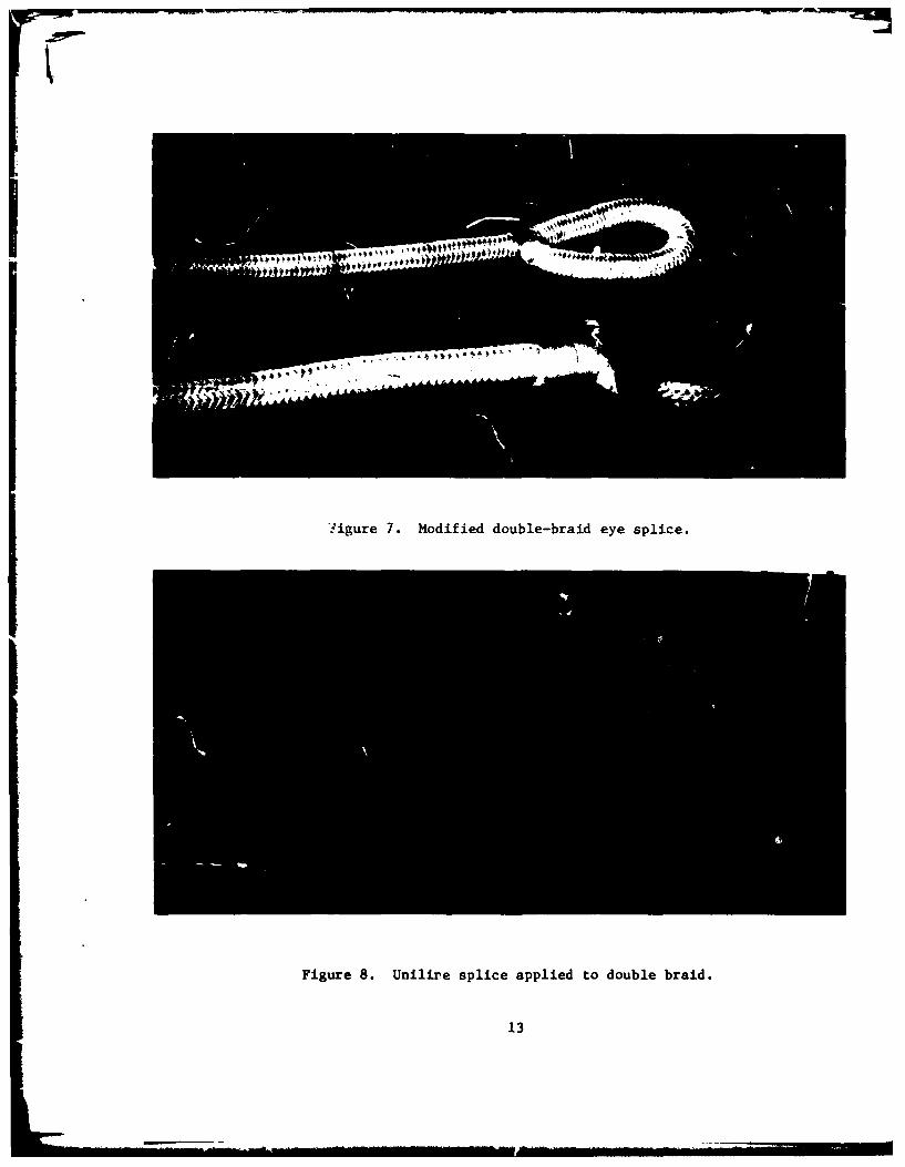
4.1.4.2 Samsor splice ('1odified Figure 7) - Useful where coreand cover are of markedly different materials, so that the cover is notfunctioning as a strengta member.
4.1.4.3 Uniline splice applied to double braid (Figure 8) - See4.1.5.2 following. May prove to be a superior method of terminating doublebraid, but requires test and evaluation. The designei ot the Uniline splicecautions (HOOD 1975) that it has not been optimized fhr constructions otherthan Uniline, and the spacing of the wraps must be modified to match thehighei stretch of other constructions.
4.1.5 Splices applicable to parallel-filament ropes -
4.1.5.1 Nelaro(R) splice - Developed by Columbian Rope Co. Relativelyquick and easy to form.
4.1.5.2 Unilinf:(R) srlice - Developed by Wall Rope Works. Soundsdifficult to make_ on first reading, but really is not. Appears (along with4.1.3.5, Figure 5) to meet the criteria of Section 3, Mechanics, betterthan any other termination found in the course of this study. Applicableto constructions other than parallel-filament; in fact to any constructionwhich can be combed out to form four bundles.
4.1.5.3 Morieras splice (See U.S. Pat. 3,411,400 in appendix) -Probably requires exceptionally long taper of tail in order to attain acceptableperformance.
5

4.2 Resin-potted terminatior, - These fittings are analogous to andderived from the zinc-poured spelter sockets which have long been employedfor the termination of wire ropes. Some resin-potted fittings are findingapplication in the field at the time of this writing, but the variety ofdesigns is so wide that it seems impractical to go beyond the illustratingof a few representative types at this time. (See Figures 9 and 10.) Somethoro'ghly successful terminat4 ons have been made, but many workers reporta scatter in their test results which is much wider than that ordinarilyachieved with eye splices. Resin potting must therefore be regarded asbeing in an experimental state. Srme of the problems are:
4.2.1 The elastic propertieE of the line, the resin and the socketare ordinarily quite different from one another, so a careful study of theirinteraction is required.
4.2.2 The insertion of the bitter end into the socket can beexpected Lo disturb the structure cf the line appreciably. See 3.5.3.Some workers have resorted to extreme measures to ease this problem, suchas suspending individual weights from the yarns during preparation for pctting(SWENSON 1975).
4.2.3 The inclusion of any air void in the socket creates a stressconcentration, which may be severe. Evacuation of the assembly after pouringhas been resorted to by some workers (HUTSON 1975).
4.2.4 Inaccurate metering or inadequate mixing of the resin leadsto inconsistent results.
4.2.5 Control of temperature and humidity during applicationis usually required.
4.2.6 Exposure to water, especially water under high pressure,affhcts the properties of some resins (FERER 1973).
For the most part, these dLficiencies are detectable onlyzy meansof destructive testing. Any resin-potted system under consideration mustbe carefully evaluated in the light of the above.
4.3 Frictional appliances - There are many merhanical devices designedto grip a line and transfer stress by means of friction. Most of thesewere designed to be aDlied to wire rope, but some are applicab1p to syntheticfibers. Most such deviceF have a working length equal to only a few linediameters, so they must be applied with relatively large normal forces inorder to transfer the stress through a relatively small area. Frictionalappliances which have been successfully applied to synthetic fiber ropesare:
4.3.' Swaged sleeves - Most frequently applied to lines of verystrall diameter but Philadelphia Resins Corp. claims acceptable resultson Kevlar(R) iines up to 200,000 lbs. rated breaking strength (Figure 11).The placement and the sequence of the swaging actions on the sleeves mayaffect the results. It has been suggested (RIE4ALD et al 1975) that long-term loading should be limited to 65% of ultimate because of stress concentrations.
6

4.3.2 Aeroquip Ropelock(R) (Figure 12) - Differs from most thimbleconfigurations in that the loop around the thimble is under full line tension.Probably intended only for service as a temporary stopper.
4.3.3 Kellems grip (Figure 13) - 1.-q most of the desirable propertiesof the Uniline splice (4.1.5.2), but is metallic, therefore subject to corrosion,and does not secure the ends of the rope structure individually. (See 3.6.4.)
4.3.4 Unnamei appliance (Figure 14) - ;tructurally and fuictionally3imilar to the foregoing, but nonmetallic. There are conflicting cl:Limsto the invention and introduction of this appliance in the U.S. It is reliablyreported to have been in use in Europe for 20 years or more.
4.3.5 No-knot eyelet (Figure 15) - Applicable to holiw braid,i.Supplied in very small sizes for application to fishing lines, buL Dotentially
useful in larger sizes.
4.3.6 Paraf~l terrination (FigurE 16) - Contains a conical plugwhich is driven into the axes of the line. Marketed by British Ropes, Ltd.
5.0 TABULAR ANALYSIS OF TEPftINATIONS
In this table, all terminations described in Section 4.0 are screeneein terms of sevel! relevant propertes. An earnest effort was made toproduce the results of the table in numerical form so that a figure o" me.:icould be derived for each candidate. It has proved 4mpracticable to producea -ale of values which cin equate such divergent properties as strengthand cost. There *s, for example, a serious danger of assigning a superiorfigure of merit to a termintion with a serious mechanical defect, on theground -hat it is cheap and aasy to apply.
The data entered into the table are, of necessity, a subtle mixtureof fact and opinion. Ttere is no body of unified information from whichtruly objective conclusions might be drawn.
6.0 THIMBLES
For those terminat ns whichi form an eye in the line, some protectionfor that eye is usuelly necessary. Thimbles of many forms have been developeoovtr the years (Figure 17); recent advances in the strength of synthetic-fiber cordage makes it necessary to reconsider the design. Common galvanizedthimbles designed for use with manila rope deform severely 4hen stressedto the breaking point of the synthetics. Cast bronze thimbles of the Newcopattern are far stronger and positively prevent the eye from slipping offthe thimble; but they are all too frequently misapplied, being shackleddirectly to common galvanized bardware for use in sea water. Galvanizedthimbles designated for service with wire rope are generally satisfactoryfor use with the older synthetics, but may deform when stressed to the breakingpoint of Kevlar(R). Tubular thimbles of polyurethane (Figures 18 and 19)have been irtroduced recently by Ocean Products Research, Inc., and appearto be successful in their resistance to abrasion. Their design should beconsidered carefully for each application to insure that the plastic does
7

not extrude in the way of the srackle pin. If necessary, the shackle pinmight be specially contoured to provide a greater bearing area.
The several types of conventional thimbles are available from a varietyof competing manufacturers in a wide range of sizes. Since their pricesas a function of size and type are itemized in all the standprd marine hardwarecatalogs, it is beyond the scope of this report to review them here. Twouncommon types are singled out for mention of cost information. The Newcocosts approximately $4.00 in the 1/2-inch size. The Ocean Products Researchthimble costs, in the 1/2-inch size, $2.50 for the tubular thimble and anadditional $2.00 for having it molded onto the eye.
7.0 CONCLUSIONS AND RECOMMENDATIONS
1. Cordage experts consulted in the course of this study were nearlyunaninous in their corziu.ion that no terminal appliance is supeior toa wr.l designed, properly made eye splice. For every type of rope construction,
there is a splice which, if properly tapered, can hold essentially the fullrated strength of the rope. Note, though, that the optimum splice is notin aii cases the one best known and most commonly used.
2. While the level of skill demanded of a splicer is not great, asense of craftsmanship is essentt al. A sloppy, uneven splice is measurablyweaker than a well made one. The importance of proper tapering cannot beoveremphasized. The time required, even for the most elaborate splices,
is not great: a competent worker can produce splices at the rate of four
to twelve per hour, depending upon the design of the splice.
3. The need for tapering may be eliminated by the use of splices4.1.3.5 (believed to be the original design of this author) and 4.1.5.2(the Uniline Rplice). These splices do not reenter and disturb the layof the standing part. The former is applicable only to the single hollow-
braid c,-qtruction; the latter is designed for use on Wall Rope's Uniline(R),but may be adaptable to others. The level of skill required for successfullyapplying these splices is probably less than that for the traditional splices.
4. It is recommended that the use of resin-potted terminations beconfined to special applications which preclude other methods. Successfulrpsin-potted terminations have been made, but the elaborate setup require-ments, the slowness of cure, 'he bndlig hazard4 inherent in epoxy resinsand the ;!fficulties of quality assurance score heavily against this approach.
5. The frictional appliance zdcribed in paragraph 4.3.4, which isnonmetallic, is worthy of serious consideration. To the author's knowledgeit has not yet found widespread application, but it appears to meet the
theoretical criteria very well. it is probably as 4uick and foolproof inits application as any termination can be.
The other frictional appliances do not appear to offer any advantageswhich offset the introduction of new metallurgical problems.
LB

a * 4 V4 IV0
-4 w-4 S0 cc IX' 0. IS L. u1% ~ %0 c
EVALUATION OF TERMINATIONS 0. 3. C 0 W
01 W 0 -O 0 V 8 O O
CU0 W~0 .- ~ -O 00
P, = = 9X
Ii. Corrosion resistance m. 0
2. Abrasion resistanceb bbcbbb
3. Impact resistance4. Strength of fixture
5. Strength of line with termination appliedffaghf
I6. Service conditions
7. Service life
8. Skill required for application kkkkk1k
9. Material or parts requires
10. Special facilities or conditions
11. Size limitations
12. Safety aspects of application and use
13. Unit costi IIIII
14. Cost of special fixtures
15. Does termination form an eye? ( 3.1) yes yes yes yes yes yes yes16. Disturbances to stress distribution:
A. Bending in a high-stress region ( 3.5.1)
B. Strand dislocation ( 3.5.2) kkI
C. Random disordering ( 3.5.3)0. Unbalance due to creep ( 3.5.4)
E. Localized compressiv stress ( 3.5.5)
F. Static off-axis loading (3.5.6)
5 . Dynamic off-axi s loading ( a3.5.7)
KEY: (Blank indicates no problem or no special consideration)
a. Subject to same limtatio, as other metallic component in sea water I.
b. No mre vulnerable than standing part . Si
c. Extra protection advised k. t
d. Avoid off-axis loading 1. r
e. Highest possible strength .. ! _
f. Slightly weaker than standing part n. S
g. Significantly weaker than staning part o. e
h. Variable
I15. Dostriainfr nee 131 e e e e e e e1,6 i t r a c s t s r s i t i u i n

IV
*00
0 oV -4 0
.C 0 UC
SU a a a%k J
Pk ~ ~~ ~ ~ ~ WkL<W 0 0 .0 > c W6
0 0." 2 4 0 "4- "4 .W 4 1.0
tt
Isys yes yes ye ye e n e no no -n c- -o e
Id M4. ..4 0-~ U-S
hh h h
k 1 k k k k I k k k
k k k k ki k
n.~~~~~ hwgn hpaau wkt hprpaede
k. Moderate iie o mle ie
m..4 Meterin and mixin apaats tepeatr and humdit cotosareacaigapaau
* It - Ulll~ l~ ll |- ...... ..... . . - .. ... !-
n. Swaln apaau wit appro.priatedies
o. deeal liie do smle ie

Figure 1. Sailor's eye splice.
Figure 2 (top). Single-braid eye splice.
Figure 3 (bottom). Single-braid eye splice with tuck.
11
Piscedig pap Mlank

Figure 4 (top). Bnnmmel splice.Figure 6 (bottom). Unnamed single-braid splice.
Figure 5. Unnamed single-braid splice.
12
k
f-igure 7. Modified double-braid eye splice.
Figure 8. Unilire splice applied to double braid.
13

Figure 9. Assorted resin-potted terminations.
Figure 10. Resin-potted termination, internal detail.
14

L.1,
Figure 11. Nicopress sleeves applied to Phillystran.
Figure 16 (top). Paraf ii termination.Figure 12 (middle). Clamping thimble.
Figure 13 (bottom). Kellems grip.
15

Figure 14. Unnamed appliance.
Figure 15. No-knot eyelet.
16

Figure 17. Assorted thimbles.
Figure 18. Ocean Produicts Research polyurethane thimbles.
17

Figure 19. Ocean Products Re&earch polyurethane thimbles,with molded vertex.
18

APPENDIX
DEVICE FOR ANCHORING A TEXTILE CABLE
19

Nov. 12, 193S3 G. MORIERAS 3,40,95DEVICE YOR Ak;CHkWRfG k TEZ13LZ C'.3L
riled Nov. 7. 1966 a et-.b.
FIG. I.
I; /:
Preceding page blank
Nov. 12, 1968 M. MORIERAS 31409t951DEVICE FOR ANCULORXNG A TEXTILE CA=L
Filed Nov. 7. 1S66 2 sbeets-sbest a
FIG.2.FIG. 3
- 2
44
22 ~ire~r

IiCOPY
UNITED STATES PATENT OFFICE3,409,951
Patented Nov. 12, 1968
DEVICE FOR ANCHORING A TEXTILE CABLEGilbert Morieras, Lyon, France, assignor to SocieteRhodiaceta, Paris, France, a French body corporate
Filed Nov. 7, 966, Ser. No. 592,610
Claims priority, application France, Nov. 15, 1965,33,390
15 Claims. (Cl. 24--123)
ABSTRACT OF THE DISCLOSURE
Anchoring device for a textile cable under tension comprising a coreformed by a bundle of parallel filaments and an external envelope coveringthe core. The device is constituted exteriorly by a rigid sleeve of taper-ing form and interiorly by a bung also of tapering form which has a commondirectrix with the sleeve and in which the end of the cable is fixed inany appropriate way. The interior apical angl. of the sleeve is less thanthe apical a'gle ci the bung. The device is particularly advantageous foranchoring cabies made of synthetic t mt !4 materials such as polyamides,polyesters and polyolefins.
This invention relates to an anchoring device, that ib to say a devicefor attachment to a fixed point, of a textile article operating undertension; such articles include cords, cables, straps, slings, etc., whichfor simpli-ity wi_1 be described by the single term "cable" in the fllowingdescription.
For some years m~tallic cables have to some extent been replaced by
cables made from synthetic textile filaments, for example polyamide orpolyester filaments. Thus some textile cables have been made which, for agiven weight per metre, have a higher resistance to break than have steelcables, and this should allow them to be used advantageously as tractionelements (e.g. as cables for masts, catenaries, buoys, ships' slings, etc.).Unfortunately textile cables have not undergone such development in thisfield of application, largely as the result of the absence of suitablemeans foi anchoring them.
To form an anchoring device with a steel cable, the wires at tb- endof the cable are untwisted and each wire is P lividually folded into theshape of a loop; the assembly of uires is then opened up and placed in asleeve the internal shape of which is generally that of a truncated cone,this sleeve serving as a mould, and finally a low melting point alloy oflower hardness and modulus than the steel comprising the wires of thecable is cast onto the folded wires. After cooling, a compact truncated
23

3,409,951
conical mass is thus obtained, called a "bung" which has been cast directlyinto the anchoring sleeve which serves as a mould. In this way the bungwhen under tension on the one hand does not damage the cable and on theother hand is sufficiently firm not to slip out of the sleeve.
Before this technique can be applied to textile cables, it is necessaryto have a casting material which at one and the same time has good adhesionand excellent chemical inertness towards the filaments comprising the cable,a casting and/or polymerisation temperature which does not cause significantdegradation of the filaments, sufficient hardness not to slip out of thesleeve when heavy tension is applied and finally a sufficiently low hardnessand modulus not to degrade the filaments when subjected to transverse forces.
To satisfy these requirements, which are in some respects incompatible,synthetic resins are used which polymerise at a low temperature, for exampleunder the action of a catalyst, such for example as epoxy resins. Howeverup to the present textile cables fitted with bungs produced by the conventionalmethod of making bungs for steel cables have not been satisfactory, becausethey cause a strength loss of between 15 and 50% in the area of the bung.(The loss in strength of a cable is given by the difference between theactual strength of the cable and its practical strength as measured withthe cable fixed at one of its ends by means of a bung.)
Up to tht bLgo prudu-.Led in practice fit the sleeve tightly,at least at the narrowest point. This arrangement would appear to lead tothe optimum fit of the bung (and hence the best retention of the cablethrough compression) whilst avoiding an elongation stress on the bung. Ithas now been found that, on the contrary, a bung which is free to stretchwithin its sleeve can give stronger anchorage than do the earlier techniques.
The arrangement of the invention successfully mitigates the disadvan-tages of the earlier means. This new arrangement consists externally ofa sleeve of a rigid material, for example metal, defining a truncatedsubstantially tapering channel, and internally of a truncated substantiallytapering coaxial bung, made of resin, having a common directrix with thechannel of the sleeve, into which the end of the cable is fixed by anappropriate method, the arrangement being characterised by the fact thatthe tangle at the top of the channel of the sleeve is less than the angleat the top of the bung. The difference between the two angles is preferablyless t.han five degrees and is advantageously about one degree.
In practice the internal forms of the sleeve and of the bung will beof very simple shapes, such as truncated cones of circular or ellipticalcross-section, truncated pyramids, truncated ovoids, or sand mounds.
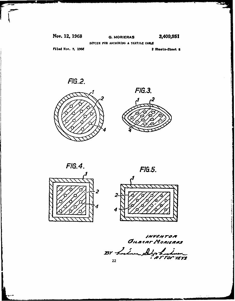
The invention is illustrated in the accompanying drawings in whichFIGURE 1 is a schematic cross-section of an advantageous embodiment of theinvention, in which 1 indicates the sleeve, 2 the resin bung, and 3 the
24

COPY
3,409,951
cable consisting of textile filaments 4, whose opened-out ends are fixedinto the bung. FIGURES 2 to 5 are schematic cross-sections of alternativeembodiments of the invention.
With the device of the invention, the textile material stretches whensubjected to a tensile stress, progressively causing the bung to rest againstan increasing fraction of the internal surface of the sleeve as the tensionincreases. In this way, contrary to what takes place with the earlier bungs,there is no sharp discontinuity between the textile material and the resinsince the latter can move freely. Thus the tensile stress is absorbed byan increasingly large part of the bung, which eventually is supported, fromtop to bottom, by the i-hole of the surface of the sleeve. Furthermore,transverse forces are a maximum at the top of the bung, that is to say wherethe tensile stress is a minimum, and conversely the compressive stress islow at the narrow end of the bung where the tensile stress is highest. Thusthe cable is not weakened, and does not break at the narrow end of the bung.
Finally, the device of the invention makes it possible for the axisof the bung in the sleeve and the axis of tension of the cable to be auto-matically made to coincide even if the bung has not been strictly cast aroundthe said axis of the cable.
Rcsins normally used in this field of application, for example epoxyresins and polyesters, may be used for the manufacture of the bung. Theseresins may with advantage be reinforced by incorporating various materialssuch as textile fibres, especially glass fibres, whilst the resin is liquid.
The device of the invention is particularly advantageous for anchoringcables made of synthetic textile materials (polyamides, polyesters, poly-olefines, etc.) and especially for cables consisting of a core formed by abundle of elementary filaments which are parallel to one another and areonly slightly twisted or not twisted at all, and at least one external coverwhich is generally plaited, especially the cables whose manufacture isdescribed in o-r French Patents Nos. 1,327,110, and 1,354,961.
The following examples illustrate the invention. An expert techniciancould easily introduce modifications, for example by simple substitution ofequivalent materials, without going outside the scope of the invention.
Example 1
99 ends of continuous polybexamethylene adipamide yarns each of 30,000deniers/5,000 strands and of 40 turns/metre Z (right hand) twist, are passedin parallel, in the form of a web, through a tank containing a self-vulcanisingenriched rubber latex. On leaving the tank, the impregnated ends are cariredvertically upwards and are then passed through a calibrating die of diameterclose to the final diameter of the cable. The drying of the binder is startedat the same time.
25

CoPY
3,409,951
The combination of ends is again impregnated with fresh binder, andthen passes into a plaiting machine comprising 24 spindles, each fed byone continuous filament end, again of polyhexamethylene adipamide, of gauge15,000 deniers/900 strands, twist 70 turns/metre (12 ends with S (left-aand)twist and 12 with Z twist.)
The assembly is then passed into a coloured polyvinyl chloride composi-tion, and thereafter into a conical elastic sleeve whose smallest diametersubstantially corresponds to the diameter of the finished cable.
!he cable continuously passes through a tunnel oven in which the tempera-ture rises progressively from 60 to 1800 C., remaining in the oven for about5 minutes.
The finished cable has a diameter of 26 mm. and weighs approximately634g./m.
A 2.70 m. sample is cut from this cable, and its two ends are untwistedover a length of about 25 cm. The component ends are opened out into contig-uous conical webs under uniform tension. A truncated conical mould is filledwith an epoxy resin composition of trade name ARALDITE, consisting of thefollowing parts by weight:
PartsEpoxy resin (CY 248) ............................................. 100Catalyst (HY 965 and 966):
Polyamide ................................................... 39Polyamide and polyamine ..................................... I
After polymerisation, each bung has the shape of a truncated cone, 16 cm.high of apical angle about 160.
Each bung is placed in a metal sleeve of apical angle 150. The cableis subjected to a tensile stress by means of a tensometer until it breaks.This takes place at a load of 20.3 metric tons and the cable breaks in themiddle of the sample.
Example 2
The same cable as in Example 1 is used but the bungs are produced bythe earlier conventional method, opening out and spreading out t'-e ends ofthe cable in the same way and casting the same resin composition into a 16cm. high sleeve having a top angle of 150 and a base diameter of 40 mm. Thecable, fixed at its twr- ends, is broken by means of the same tensometer asbefore. The break takes place within the bung at a load of 13.4 metric tons.The comparison between Examples 1 and 2 perfectly illustrates the advanceachieved by the device of the invention.
26

3,409,951
Example 3
Example I is repeated with only a single change, namely that the corefilaments of polyhexamethylene adipamide are replaced by continuous poly-
ethylene terephthalate filaments.
Breakage takes place in the middle of the sample, at 17.8 metric tons.
Example 4
Example 2 is rzkpeated with the same cable as in Example 3. Breakagetakes place within the bung at a load of 13.2 metric tons.
I claim:
1. Device for anchoring a textile cable operating under tension,which comprises a core formed by a bundle of substantially parallel elemen-tary filaments and at least one external envelop covering the said core,the device being constituted exteriorly by a rigid sleeve of generallytapering form, and interiorly by a resin bung, also of generally taperingform which has a common directrix with the sleeve and in which is fixedin any appropriate way the end of the cable, characterised in that theinterior apical angle of the sleeve is less than the apical angle of thebung.
2. Anchoring device according to claim 1, in which the differencebetween the two apical angles is less than 50.
3. Anchoring device according to claim 2, in which the differenceis close to 10.
4. Textile element equipped at at least one end with an anchoringdevice comprising in combination a rigid sleeve defining a truncated taperingchannel, and contained within it a truncated tapering resin bung in whichthe end of the cable is so fixed that the free part of the cable emergesfrom its narrow end, the bung being substantia l',, -oaxial and having a commondirectrix with the channel of the sleeve and LV interior apical angle ofthe sleeve being less than the apical angle o' the bung.
5. Textile elements according to claim in which the difference
between the two apical angles is less than 5
6. Textile elements according to clal 5, in which the difference is
less than 10.
7. Textile elements according to claim 5, consisting essentially ofa synthetic polymer.
27

3,409,951
8. Anchoring device according to claim 2 in which the intarior ofthe sleeve and the bung have the form of a truncated cone ot circularcross-section.
9. Anchoring device according to claim 2 in whicl- the interior ofthe sleeve and the bung have the form of a truncated cone of elipticalcross-section.
10. Anchoring device according to claim 2 in which the interior ofthe sleeve and the bung have the form of a truncated pyramid.
11. Anchoring device according to claim 2 in which the interior ofthe sleeve and the bung have the fort of a sand mound.
12. Textile elements according to claim 5 in which the interior ofthe sleeve and the bung have the form of a truncated cone of circularcross-section.
13. Textile elements according to claim 5 in which the interior ofthe sleeve and the bung have the form of a truncated con" of elipticalcross-section.
14. Textile elements according to claim 5 in which the interior ofthe sleeve and the bung have the form of a truncated pyramid.
15. Textile elements according to claim 5 in which the interior and
the sleeve of the bung have the form a sand mound.
References Cited
UNITED STATES PATENTS
2,048,292 7/1936 Rau ..................................... 24- 123.13,263,289 8/1966 Lagarde .................................. 24-123.23,283,380 11/1966 Gassner ................................. 24-123.2
BERNARD A. GELAK, Primary Examiner.
28

Nov. 19, 1968 G. MORIERAS ET AL 3,411,400SFLICZ;D LOOF AND Mr7THCD ' F FOEMATION THEREOF
Filed Sept. C, 136~7 2 Sheets-Sheet
F/G 2,
5 -1
FIG.3.
yjInenor
29
Attoney

Nov. 19, 1968 G. MORIERAS ETAL 3,411,400SPLICED LOOP AND M-HC2 OF FORMATION THEREOF
Filed Sez;.. 1957 2 Sheets-Sheet
FIG. 4.
'.\ 1
/P
-- 6
30

United States Patent Offce 3.oo,1,400.3,411,400Unitd Sttes aten Offce aitented Nov. 19, 1968
1 2has been removed spaced from said first portion, at least
3,411.400 two bundles of filaments in said second uncovered portion,SPLICED LOOP AND METHOD OF and at least two bundles of filaments in said first un-FORMATON TI !EREOF covered pcrtion, braided with said at least two bundles of
Gilbert Morieras and lic':el Scr de Lanauze, Lyon, 5 said second portion.France, a~signor:i to Soci. te zItliacea The invention also provides a method of forming aFlied Sept. 6, 1967. Scr. No. 665,793
Clams priorit), application France, Sept. 20, 1966, spliced loop in a textile rope consisting of a plurality of77,007 parallel textile core filaments covered by an envelope,
8 Claims. (C]. 87-8) such method comprising strippiag the envelope from the10 core adjacent a free end of the rope to provide a first un-covered portion of said core filaments, stripping the enve-
lope from the core at a position spaced from said firstABSTRACT OF THE DISCLOSURE uncovered portion to provide a second uncovered portion
The invention describes a spliced loop in a textile of said core filaments, collecting the filaments of said firstrope, and method cf- taking su:h a loop, in which the 15 uncovered portion into a first set of at least two bundles oflope consists of a plurality of parallel textile core fila- filaments, collecting the filamcnts of said second un-mn.nts covered by ai erveiope and comprising a first vn- covered portion into a second set of at least two bundlescovered portion of said rope from % hich the envelope has of filaments, and braiding the bundles of said first set withbeen removed adjacent tbe free end thereof, a second the bundles of said second set to form said loop.uncovered portion of said rope. from which the e velope 20 In practice n 'dead" bundles and n- "live" bundleshas been removed spazed from said first portion. at least are formed. This number n is obviously a function of thetwo bundles of filaments in said second uncovered por- diameter of the rope and the selection thereof is withintion, and at leasot tv. o bund!es of filaments in said first the scope of the person skilled in the art. For ropes theuncovered portion, braided with said at least two bundles diameter of which is of the order of one centimeter, n isof said second portion. 25 generally equal to 3.
In the present description, the expression "stripped"designates the rpcrati,.mn which consists of removing from
The present invention relates to a spliced loop formed the rope the enselope surrounding the core formed by theat the end of a textile rope, and also to a method for the assembly of parallel filaments.manufacture thereof. 30 In order that the invention may more readily be under-
Recently, a rope has been proposed which consists of stood the following description is given, merely by wayan assembly of parallel textile filaments. generally of of example, reference being made to the accompanyingsynthetic origin and constituting a core, coered by an drawing-, wherein:envelope, which is for example braided or extruded arourd FIGURE I is a schematic side elevation of a rope hay-the said core. An example of such a rope is described in 35 ing parallel core yaras and a braided covering, illustratingFrench Patent specification No. 1.327,110. As compared the first stage of forming a loop according to the inven-with conventional stranded or brided textile ropes these tion;ropes are lighter due essenliaily to the absence of shorten- FIGURES 2 and 3 are views sinilar to FIGURE 1ing (stranding) and, conseqjently, by greater strength ~illustratin2 the second and third staes; andfor equal diameter or %eight. Moreover. when in use '0 FIGURE 4 is a further similar view illustrating thethey stretch only to a sma!i degree and, relatively to final stages of the formation of the loop.stranded ropes, they exhibit abose all permanent anti- The drawings show substantialll the carrying out of thegiratory properties. method of the inventicn. In one particular example, the
Relative to steel cables, apart from the majority of 4 rope used had as its core 48 x 10.000-denier core :lementsthe preceding functional properties, these ropes exhibit and 36x30,000-denier core elements each formed froma gh degree of flexibility and excellent handling quai- continuous polyhexamethylene adipamide filaments as-ties. semblcd without twist and joined together by a latex. ThisIn a conventional rope or cord, which is stranded or core was e.losed in a braid produced on a machine hav-i n a con enti nal rope or ord whi h i str nd e or ing 24 spindles fed w ith a 10 000-den ier rove fo rm ed fro mbraided in order to produce a terminal splice (also known 50 continuous filaments of polhexameth lene adipamide.as a spliced loop), the free end of the rope, the "dead"strand, is unstranded or unbraided as the case may be, and The comp!cted rope weighs approximately 315 grams/is interlaced with the "live" strand at a distance equal to metre and has a diameter of 20.5 mm.the developed length of the loop which it is desired to In forming the loop according to the invention as shownform. This interlacing operation, which is a delicate opera- 55 in FIGUk :, the braid I forming the envelope was re-tion and one which requires a considerable amount of time moved, firstly at the free end of the rope over a lengthto effect, is carried out ' ith the aid of a manual apparatu, of 60 cm. to form the "dead" strand and secondly overknown as a "splicer." Due to the interlacing of the fila- a length 3 of 40 cm., located entirely within the "live"ments of the "dead" strand with those of the "lie" strand, strand of the rope, at a distance fior the "dead" strandthe cabling and stranding torsions maintain the assembly 6o 2 which was approximately equal to the devc'oped lengthin equilibruim. The spliced loop formed is then self- of the spliced loop which it was desired to 2roduce Le.,locking, in thib case 90 cm.
The application of this principle to a rope formed by an As shown in FIGURE 2, the "dead" strand 2 wasassembly of parallel filaments is obviously impossible, due divided into three substantially equal bundles 4 and theto the absence of elementary strands. C; "live" strand 3 into two also substantially equal bundles
According to on. apect oi the preent invention there S. Aftcr having foldcd bunJlcs 4 to a position adjacentis provided a spliced loop in a testile rope in which the bondles S as shown in FIGURE 3. the three bundles 4 ofrope consists of a plurality of parallel textile core fila- the "dead" strand were braided, in a conventional man.ments covered by an envelope and comprising a first un- ner, on the two bundles 5 of the "live" strand (FIGUREcovered portion of said rope from R hich the envelope has 70 -4), the bundles 4 being passed over the bundles 5 tenbcn remosed adi.cent the fr:" cand thc;of. :, second un- times.covered portion of said rope, front which the envelope In order to improve the appearance of the spliced rope.
31 eproduced frompy.best available copy,

3,411,400 4
the splice may be surrounded by a lacing 6 and/or a braided bundles are covered with a vulcanised rubbervulcanised rubber strip. strip.
In FIGURE 4 the braiding of the bundles 4 and S and 5. A method of forming a loop in a textile rope, saidthe lacing are shown symbolically aind iutention~Aly de- method comprising the steps of:formed, so as to facilitate understanding of the invention. 5 (i) providing a textile rope including a plurality of
With the aid of a dynamnomnctcr. this rope, retained by parallel textile core filaments and an envelope andthe spliced loop, was subjected to a tensile force until having a fiee end;rupture occured under a load of 11.5 metric tons. The (ii) stripping the envelope from the core filaments ad-fracture took place in the "heart" of the test piece, i.e., in jacent the free end to provide a first uncovered por-the portion located outside the spliced loop. 10 tion of said core filaments;
The spliced loops produced in accordance %ith the (iii) stripping the envelope at a location spaced frominvention are antigoiratory by nature; furthern;ore, the said first uncovered portion to provide a second un-bundles of the "live" strand remain subtantially parallel covered portion of said core filaments:and the braiding of thte bundles of the "dead" strand is (iv) collecting the filaments of said first uncovered por-balanced. Additionally they are flexible and, in use. 1 tion into a first set of at least two bundles of fila-notably due to the absence of stranding, the,e sp'iced ments;loops exhibit hardly any tendency to stretch. Simihrly. (v) collecting the filaments of said second uncoveredunder the influence of a tensile force, these loops A:-o portion into a second set of at least two b.,'dles ofhave the property of being self-locking, filaments; and
We claim: 20 (vi) braiding the bundles of said first set with the1. A spliced loop ip a textile rope comprising in bundles of said second set to form said loop.
combination: 6. The method defined in claim 5, and including col-(a) a textile rope including a plurality of parallel tex- lecting the filaments of said first uncovered portion into
tile core filaments and an ervelope; three bundles, and collecting the filaments of said second(b) a free end to said textile rope; 25 uncovered portion into two bundles.(c) a first uncoverod portion of said rope having the 7. The method defined in claim 5 and including the step
envelope removed adjacent said free end. of covering the braided bundles with lacing.(d) a second uncovered portion of said rope spaced S. The method defined in claim 5 and including the
from said first uncovered portion and having the step of covering the braided bundles with vulcanised rub-envelope removed therefrom: 30 ber strip.
(e) at least two bundles of fi-ments to said second References Citeduncovered portion: and UNITED STATES PATENTS
(f) at least two bundles of filaments to said first un- 1,524.671 2,1925 Nyman et a]. 87-8covered portion, braided sith said at least t% ,524.674 11/1925 Pyman t87-0bundles of said second portion. 35 2,575974 11/1951 Peterson.---------------7-8
2. The spliced loop defined in claim 1, wherein said 3,013,463 12/1961 Gathman et al .--------- 87-first uncovered portion includes three bundles of fila- 3,018,319 1/1962 Quayle.
ments, and s.-id second uncovered portion includes tsso FOREIGN PATENTSbundles of filaments. 226,862 1/1960 Australia.
3. The spliced loop defined in claim 1, wherein said 40braid-.d bundles are covered %ith a lacing. JOHN PETRAKES, Primary Examiner.
i. The spliced loop defined in claim 1, wherein said
32
BIBLIOGRAPHY
ASHLEY, C.W. (1944) The Ashley book of knots. Doubleday Doran.
FERER, K.M. (1973) Factors affecting epoxies used as wire ropeterminators in the sea. NRL Memorandum Report 2646.
HOOD, H.A. (1975) Private communication.
HUTSON, R. (1975) Private communication.
RIEWALD, P.G. and T.K. Venkatachalam (1975) Kevlar aramid fiber forrope and cable applications. Marine Technology Soziety, Cableand Connector Committee.
SWENSON, R.C. (1975) Private communication.
U. . GO - 4RN 7 PRINTTI (FICE: 1976--602-672--171 3 3