
A review of fault tolerant control strategies applied to ...
26
HAL Id: hal-01624984 https://hal.univ-reunion.fr/hal-01624984v2 Submitted on 2 Sep 2021 HAL is a multi-disciplinary open access archive for the deposit and dissemination of sci- entific research documents, whether they are pub- lished or not. The documents may come from teaching and research institutions in France or abroad, or from public or private research centers. L’archive ouverte pluridisciplinaire HAL, est destinée au dépôt et à la diffusion de documents scientifiques de niveau recherche, publiés ou non, émanant des établissements d’enseignement et de recherche français ou étrangers, des laboratoires publics ou privés. Copyright A review of fault tolerant control strategies applied to proton exchange membrane fuel cell systems Étienne Dijoux, Nadia Steiner, Michel Benne, Marie-Cécile Pera, Brigitte Grondin-Perez To cite this version: Étienne Dijoux, Nadia Steiner, Michel Benne, Marie-Cécile Pera, Brigitte Grondin-Perez. A review of fault tolerant control strategies applied to proton exchange membrane fuel cell systems. Journal of Power Sources, Elsevier, 2017, 359, pp.119-133. 10.1016/j.jpowsour.2017.05.058. hal-01624984v2
Transcript of A review of fault tolerant control strategies applied to ...

HAL Id: hal-01624984https://hal.univ-reunion.fr/hal-01624984v2
Submitted on 2 Sep 2021
HAL is a multi-disciplinary open accessarchive for the deposit and dissemination of sci-entific research documents, whether they are pub-lished or not. The documents may come fromteaching and research institutions in France orabroad, or from public or private research centers.
L’archive ouverte pluridisciplinaire HAL, estdestinée au dépôt et à la diffusion de documentsscientifiques de niveau recherche, publiés ou non,émanant des établissements d’enseignement et derecherche français ou étrangers, des laboratoirespublics ou privés.
Copyright
A review of fault tolerant control strategies applied toproton exchange membrane fuel cell systems
Étienne Dijoux, Nadia Steiner, Michel Benne, Marie-Cécile Pera, BrigitteGrondin-Perez
To cite this version:Étienne Dijoux, Nadia Steiner, Michel Benne, Marie-Cécile Pera, Brigitte Grondin-Perez. A reviewof fault tolerant control strategies applied to proton exchange membrane fuel cell systems. Journal ofPower Sources, Elsevier, 2017, 359, pp.119-133. �10.1016/j.jpowsour.2017.05.058�. �hal-01624984v2�

1
A review of fault tolerant control strategies applied to proton
exchange membrane fuel cell systems
Etienne Dijoux1,2,3 *, Nadia Yousfi Steiner2,3,4, Michel Benne1, Marie-Cécile Péra2,3, Brigitte Grondin Pérez1
1 LE2P, EA 4079, University of La Réunion, 15 Av. René Cassin, BP 7151, 97715 Saint-Denis, France
2 FEMTO-ST, CNRS / Univ. Bourgogne Franche-Comte, Belfort, France
3 FCLAB, CNRS / Univ. Bourgogne Franche-Comte, Belfort, France
4 Labex ACTION, CNRS, Belfort, France
E-mail addresses: [email protected], [email protected], [email protected], mc.pera@femto-
st.fr, [email protected]
* Corresponding author: [email protected]
Phone: +33(0) 384 583 626
Fax: +33(0) 384 583 636
Abstract – Fuel cells are powerful systems for power generation. They have a good efficiency and do not generate
greenhouse gases. This technology involves a lot of scientific fields, which leads to the appearance of strongly inter-
dependent parameters. This makes the system particularly hard to control and increases fault’s occurrence frequency. These
two issues call for the necessity to maintain the system performance at the expected level, even in faulty operating
conditions. It is called “fault tolerant control” (FTC). The present paper aims to give the state of the art of FTC applied to
the proton exchange membrane fuel cell (PEMFC). The FTC approach is composed of two parts. First, a diagnosis part allows
the identification and the isolation of a fault; it requires a good a priori knowledge of all the possible faults. Then, a control
part allows an optimal control strategy to find the best operating point to recover /mitigate the fault; it requires the
knowledge of the degradation phenomena and their mitigation strategies.
Keywords: PEMFC; Modeling; degradation; diagnosis tools; Fault Tolerant Control
I. Introduction
Fuel cells (FC) are recognized as efficient and environmentally friendly systems for power generation. Their operation
involves however, several scientific fields, which results in strongly correlated parameters. This makes these systems
particularly complex and hard to control, and increases the probability of fault occurrence. Low reliability and short lifetime
are still bottlenecks to be overcome for a wide deployment of these systems.
Therefore, the last few decades have seen several researches aiming at better understanding and improving the operation of
these systems. For instance, Wakizoe et al. [1] studied three different fuel cell’s membranes, and highlighted their
physicochemical effects on performance. They showed that the current density, the electrode kinetic parameters or the value
of membrane resistance in the linear region (ohmic region) of the polarization curve have consequences on fuel cell’s
performance. Other studies are dedicated to the energy consumption [2]–[7], to the safety [8], [9] and to the performance

2
improvement [10], [11], [12], [13], [14], [15], [16]. Jouin et al. [17] addressed the PEMFC system short lifetime issue and
proposed to use a prognostic and health management (PHM) approach in order to extend the FC life span. The authors
enumerated each step of the PHM as follows: data acquisition, data processing, data assessment, diagnosis, prognostic,
decision support and human machine interface. For now, a lot of work has been covering the steps ranging from data
processing to prognostic [3], [7], [9], [18]–[94], and many papers dealing with the fuel cell control were published [2], [4], [5],
[10]–[13], [15], [16], [95]–[105]. However, the major part of these papers suffer from a lack of FC State-of-Health
considerations in the design of the control itself, when it is known that setting appropriate control actions to counteract faulty
operating modes, results on higher availability, reliably and larger lifespan.
Defining the control actions by taking into account the fault diagnostics is known as Fault Tolerant Control (FTC), and as far as
we know, FTC applied to fuel cells has not been studied a lot, and represents a novel approach for performance optimization
of PEMFC. It is a very efficient approach to guaranty PEMFC’s survivability, reliability and maintainability.
This paper is organized as follows: the second section describes the existing faults in PEMFC and their characteristics. This part
enables to get a better understanding of their mechanisms and effects on the system, and to identify the relevant associated
parameters. Then, possible alternative approaches for different faults mitigation are given in the same section, while control
and fault tolerant tools are presented in the following sections III. In the section IV, the most suitable strategy according to
the performance requirements and experimental constraints is given. Sections V analyzes fault mitigation strategies for PEMFC
performance and lifespan. The section VI concludes the paper.
II. PEMFC Diagnosis
A. Faults
PEM fuel cell stacks and systems can be subject to different faulty operating modes. Piechowiak et al. [106] define the fault
as a system’s performance degeneration caused by significant or minimal degradations, and several studies classify faults
according to different criteria such as effects, response time, reversibility and localization.
To ensure a proper operation of the FC, the operating parameters must be kept in a narrow range of operation. For instance,
water management is a complicated task in PEMFCs since any disequilibrium in the water balance, leads to issues such as cell
flooding or membrane drying out. Flooding is defined as an accumulation of liquid water in the gas channels or electrodes,
impeding the access of reactive gases to the active layers, and therefore decreasing the reaction rate [58]. Li et al. [58]
identified flooding as one of the most recurrent PEMFC’s faults, and stated that the cathode is more subject to flooding as it
is the locus of water production. The flooding probability increases with high current levels, higher inlet gases temperature
than the stack’s one, or when the humidification of inlet gases is excessive. The lower the O2 diffusion rate is, the more
important the flooding will be: the authors defined four magnitudes of flooding, where a higher magnitude calls for more
important performance loss [58]. At the opposite, a drying out can occur if the membrane is not sufficiently hydrated, which
results in membrane resistance’ increase. It occurs when the inlet gases’ temperature is below the FC operating one [21] or
when the inlet gases are insufficiently humidified. The phenomenon is detectable by any increase of cell resistance.
Another kind of faults is the short-circuit. Silva et al. [79] studied its impact on a 3.8 kW PEMFC performance: during a couple
of seconds, a short-circuit reaction produces a large quantity of water, decreasing the cell membrane resistivity and
eliminating oxygenated species from the platinum surface, which increases the system’s performance. However, during short-
circuit conditions, high thermal gradient appears and local hot spots occurs at the membrane. Moreover, reactant cannot be
injected fast enough, therefore a concentration gradient and local starvation occurs and induces irreversible degradations.
Yousfi-Steiner et al. [90] defined the starvation as an undersupply of reactants that could occur either at local or global level.
The first one refers to local undersupply of reactants associated with irregular reactants distribution, while the overall supply

3
at cell level is high enough. The global starvation denotes an overall undersupply of reactants at cell level. In both cases, the
gas flow rate and the relative humidity will exacerbate the starvation that could rapidly induce irreversible corrosion
phenomena such as carbon reduction or platinum oxidation.
Another potential fault linked to reactants supply is FC poisoning [70]. At the anode side for instance, the lower the purity of
intake reformate hydrogen is, the higher the risk of hydrocarbons traces will be: the adsorption phenomenon due to CO
poisoning at the platinum anode catalyst surface induces a catalyst deactivation that leads to performance loss [88][86]. The
CO poisoning depends on the inlet gases content, inlet flow rate, humidity, residence time and temperature.
When a fault occurs, its effects are not instantaneous, due to the characteristic duration of the fault setting. The response
time of flooding and drying out reflects the dynamics of water (from one second to several minutes). In the case of
hydrocarbons poisoning, the response time span is longer. It starts from one second to a day during long-term operations.
Starvation is much faster, with a response time ranging from one millisecond to approximately one second. As electric
phenomenon, the short-circuit has the fastest response time, and its response time interval varies from one microsecond to
several milliseconds [84]. Table 1 summarizes these faults by response time, involved parameters, effects and reversibility
capabilities.
Fault Response time
(second) Effects Reversibility
Involved parameters
Short-circuit 10−6 to 10−2 Membrane and catalyst layer
degradation [79]
Irreversible in the case of local heating
or starvation
Relative humidity, temperature, gas flow rate, partial
pressure (example of this phenomenon in [107])
Starvation 10−3 to 101 Catalytic layer degradation [90] Irreversible
Relative humidity, temperature, gas flow rate, partial
pressure, current (example of this phenomenon in
[107])
Flooding 100 to 103
Performance losses and slow
system degradation due to
starvation and material alteration
[58]
Entirely reversible if treated in time
Gas flow rate, current, relative humidity (example of
air starvation in the article of A. Taniguchi et al. [81])
Drying 100 to 103 Performance losses and pinhole
degradation of the membrane [21] Entirely reversible if treated in time
Stack temperature, relative humidity, gas
composition, exposure time [90]
CO Poisoning 101 to 105 Performance losses and then
starvation [70]
Reversible depending on exposure
time, temperature and inlet gas
composition
Relative humidity, temperature, gas flow rate, partial
pressure (example of this phenomenon in [107])
Table 1: Faults in PEMFC, effects, response time, relevant parameters and reversibility
As stated before, each fault has a specific response time and influences differently the FC performance. The cell exposure
time to the fault is a key factor that determines the capability to recover performance, for the major part of the faults.
Therefore, defining corrective actions is crucial. Furthermore, a sole corrective action cannot be considered for all possible
faults and an efficient correction should be adapted to the nature of the identified fault: a suitable control strategy has to be
applied for each fault and, in some cases, each level of faults’ severity. This is why a proper diagnosis of the fault is needed
prior to define the involved parameters, the adapted corrected actions and the suitable control.
B. Diagnosis tools for PEMFCAs summarized in Figure 1, diagnosis techniques are generally divided into two groups: residual-based and data-based
methods. The residual-based diagnosis compares a healthy PEMFC’s model outputs to the real system measurements.
Residuals are analyzed to detect the fault occurrence, and symptom matrix is generated to identify the faults. The data-based
diagnosis uses data processing techniques. It is based on the human knowledge or on techniques that utilize a set of input
and output data to rule on a fault occurrence. Data are then analyzed to determine the distance between faulty operating
conditions and nominal operating ones, and to take decision regarding diagnostics. Some works are based on neural networks
NN [78] [89] or Bayesian network BN [74]. Yousfi-Steiner et al. [89] for instance, used a NN to diagnose flooding and drying

4
out. The model inputs are: current; airflow rate; saturation temperature; stack temperature and the outputs are voltage and
anode/cathode pressure difference. Residuals are then computed and a threshold function is used for decision-making.
Riascos et al. [74] developed a BN to detect faults in the air fan, in the refrigeration system or for the growth of FC crossover
and the hydrogen pressure. Authors used the Bayesian-score (K2) and Markov chain Monte Carlo algorithms for an automatic
generation of the graph.
Other works focused more on signal processing tools: Pahon et al. [69] propose a novel method that consists of applying a
discrete wavelet transform (DWT) to the PEMFC output voltage or pressure drop. The comparison of the resulting coefficients
to the healthy ones allowed a proper diagnosis of a high air stoichiometry condition. Another proposed method by Damour
et al. [31] consisted of using the empirical mode decomposition (EMD) to decompose a signal in intrinsic mode functions, on
a sliding window of 60 seconds and with a sampling frequency rate of 1 kHz. The on-line method allows to detect and identify
a flooding and a drying out fault. In another work, Legros et al. [56], explored the frequency domain with power spectral
densities (PSD) to detect and identify flooding and drying out faults. This PSD is based on the on-line measurement of the
electrochemical noise (EN) which is directly done on the fuel cell electrodes and digitized at several sampling rates. They
highlighted that EN is lower under humidified gas operation than in dry conditions. Finally, Ma et al. [108] used the pressure
drop (PD) signal as diagnostic tool to study the dynamics behaviors of a PEMFC. Their goal was to correlate the pressure drop
at inputs/outputs of the channels with their liquid water content. The study showed that the PD measurement is well
correlated to the liquid water content and therefore is a suitable diagnosis tool for flooding.
Zheng et al. [93] made use of characterization tool such as the electrochemical impedance spectroscopy (EIS) to diagnose
oxygen starvation, water flooding and drying: Through a 4-steps Pattern recognition (PR) methodology (feature extraction,
feature selection, fault detection and fuzzy clustering), the authors were able to rule on fault occurrence. Other PR tools, such
as support vector machine (SVM) are also used by Li et al. [59] and Data-based statistical methods such as Signed Directed
Graph Method (SDG) by Hua et al. [48] and Giurgea et al. [42].
Figure 1: Approaches and methods for diagnosis
The choice of one approach over the other depends mainly on the user's knowledge and available data. In general, the
diagnosis should provide the closest results to reality (reliability), with a good processing time (quickness) that allows real-
time applications (rapidly triggering corrective actions will reduce the exposure time to fault). It should also react to a large
range and different amplitudes of faults (sensitivity), be applicable for different fuel cells (genericity) and have a strong on-
line capability to allow supervision [71]. Furthermore, the nature of the diagnosis is a key criterion of choice: passive
diagnostics uses only the existing input/output system signals to detect the fault, while active one consists of exciting the

5
system to detect faults faster or to amplify the FC system response [41]. Table 2 gives an overview of the methods and their
criteria of choice:
Diagnosis and data
computing tools On line reliability Quickness Sensitivity Genericity
Non
linear
response
DWT Yes High High High High High
EMD Yes High High High High High
EN Yes Good Good Good High High
EIS
with pattern
recognition and
classification tools
Usually no, but it is possible
with a converter on a static
point [93] Good High High High High
BN Yes High High High High High
NN Yes High High High High High
SDG Yes High High High High High Table 2: Classification of diagnosis method with their constraints
The table A1 in annex A summarizes each previous method. When experimental data are used, information on the considered
stack or cell is given to detail the validation domain of the presented tool.
III. Control strategies for PEMFCMany kinds of control strategies for a PEMFC system exist, and some of them are presented below. Indeed, each control
strategy describes different ways to regulate flow rates, input gases temperature and humidity. For instance in case of mass
transfer phenomenon for PEMFC, Wang et al. [2] designed a robust control with a Hinf controller to regulate hydrogen flow
rate in order to improve the fuel cell performance. The principle is to define the features of a nominal plant and the features
of a disturbed one, to minimize the maximum gap between them. This kind of controller allows reducing the hydrogen
consumption while guaranteeing fuel cell performance. In their article, Garcia-Gabin et al. [10] proposed a single input single
output Sliding Mode and a feedforward action to control the air feed of a PEM fuel cell. The feedforward action aims to
provide a swift move to reach the final steady state value with reference to the current of the stack. The sliding mode
controller is also used to mitigate the transitory effects of the load change and any other considered disturbances. Again a
sliding mode strategy has been used by Kunusch et al. [12] to control the inlet flow rate of oxygen for a PEM fuel cell
(transportation applications). In this case, a super-twisting algorithm allows to avoid chattering phenomenon. Another
technic based on backstepping controller with an adaptative one has been used by Li et al. in [11]. These controllers are
directly applied on the nonlinear system model without linearization. Here, the aim is to maintain the oxygen excess ratio
around the desired value. Another work has been done by Liu et al. [109] on a 150 kW hybrid tram heavy duty PEMFC engine.
They developed a semi-mechanical semi-empirical air supply system model that is embedded in the control fuel cell system.
The goal is to control a centrifugal air compressor following the duty cycle on the engine. The control system is also composed
by a feed-forward PID controller that shows good response time and accuracy during simulation and experimental tests. This
work is relevant because the air supply control and therefore of the compressor is a big issue for fuel cell lifetime as air
starvation has to be avoided and consumption of the compressor which decreases the output net power. Then, Sanchez et
al. [110] propose an air feed system control of a PEM fuel cell system by an adaptive neural network. The neurocontroller is
then used on a PEMFC hardware-in-the-loop emulator.
Fuel cell and inlet gases temperature are also leading parameter involving research for control strategies. For instance, Cheng
et al. [111] proposed to control a fuel cell temperature of city bus to improve its efficiency. Indeed, they work on a warm-up
method to optimize the global efficiency. Authors justifying the value of their work by comparing the maximum equivalent
energy consumption case with their strategy. They underline that it can save 4.69 MJ when the warm up time is 1000s.

6
A fuzzy logic-based water heating control was proposed by Tabanjat et al [102]. The goal is to control the water supply of a
PEM electrolyzer to a pre-determined temperature via a controlled water flow circuit in order to enhance PEM efficiency.
Here, a fuzzy logic controller is used to maintain the water temperature to its reference value.
Another work related with energy management has been done by Sid et al. [6] proposing an optimal command for the energy
management of a PEMFC hybrid vehicle. The objective is presented as an optimization problem based on the minimum
Pontryagin principle and on Hamiltonian function. The goal is to minimize the fuel consumption for a given profile.
Finally some dealing with control optimization and degradation decreasing through model predictive controllers.One of the
proposed work was done by Barzegari et al. [112] applied on a cascade type PEMFC. The aim is to track the desired voltage
trajectory of a stack which operates in a dead-end mode. The MPC makes an online optimization of the future control moves.
Authors underline the good performance of their strategy in tracking desired trajectories and give the maximum relative error
between the simulation and experimental results less than 10%. Zhang et al. [113] also work on a model predictive controller.
They have shown interest for irreversible degradation of internal composition such catalyst layer or membrane and propose
to focus their work on water management in PEMFC. The work is based on a water management system model and a model
predictive control by using a recurrent neural network. The goal of this strategy is to avoid fluctuation water concentration
in cathode and extend the lifetime of the fuel cell. The work of Zhang et al [113] took into consideration the fuel cell state of
health. Indeed, their control objectives is to maintain an appropriate water distribution in the anode side. By this way, some
degradations and thus loss of performance due to the water concentration can be reduced. This kind of consideration is a
major issue for fuel cell lifetime and should be extended to other fuel cell fault for a better lifetime improvement.
The previous articles highlight two mains control objectives. The first one is to minimize the fuel consumption. These types
of control make sense because of the high costs of hydrogen. The second one focuses on the fuel cell state of health. Indeed,
the willingness in some cases to reduce the transitional effects and to inject gas with the best fuel cell operating temperature
is a major issue for the fuel cell lifetime. This is due to the relatively short lifetime of fuel cell systems. However, it is important
to note that except for the last cited work [113], in all the other cases most of control laws hardly consider fault occurrence,
and therefore fuel cell state of health (SoH). Table A2 is a summary of papers dealing with PEMFC control.
IV. Fault tolerant control
Fault Tolerant Control (FTC) is the ability of a system, through its control, to absorb any unexpected event while continuing
to deliver the required performance [114].
For PEMFC systems, fault occurrence is highly probable, due to the strong parameter coupling. In order to improve the
reliability, a fault tolerant control strategy is therefore needed to make the system fulfill the application requirements and
fulfill its mission. However, the challenge is to develop a control law for faults occurrence in real-time. Therefore, faults have
to be identified fast enough to avoid any irreversible degradation. Zhang et al. [92] proposed two ways to develop a FTC
strategy: the Passive FTC (PFTC) and the Active FTC (AFTC). Each strategy has particular strengths and drawbacks.
Lebreton et al. [115] and Oudghiri et al. [116] defined the PFTC as an anticipated compensation of faults, with the following
characteristics:
In the PFTC strategy, the control is designed to be robust to a small range of predefined faults, which allows avoiding
both the use of a diagnosis tool and the reconfiguration of the control law.
This strategy is only tolerant to the predefined and considered faults (usually small set of predefined faults).

7
If too many faults are considered, it could decrease the controller performance. It is also able to reject these
predefined faults while maintaining the optimal performance in closed-loop.
The PFTC is designed off-line, and all of its parameters are predefined [114]. This implies a low computation time
suitable for real time applications, no diagnosis nor control reconfiguration is needed.
The AFTC strategy has the ability to give an appropriate response to any variation of the physical parameters of the system
(fault). It requires therefore a diagnosis tool to maintain the system stability and performance. As for PFTC, in case of
unrecoverable faults or partially recoverable faults, AFTC maintains the system stability, even in a degraded mode. Figure 2
shows the different possible control strategies for a FTC.
Figure 2: FTC strategies
For an AFTC architecture, a diagnosis and a decision-making system are introduced to determine the best control strategy for
a fault mitigation. Figure 3 shows a combination of the diagnosis, the decision-making system and the controller results in the
AFTC strategy:
Figure 3: AFTC strategy
A. Decision making structure
The decision-making module is the link between the diagnosis module and control module in the case of FTC strategy.
Zhang et al. [117] cited in their paper some existing reconfigurable controller as the linear quadratic regulator, the
eigenstructure assignment, multiple model, and others. They highlight that these methods suppose a perfect diagnosis
tool and the post-fault model completely known. For this reason, in the case of a FTC strategy on a PEMFC system, a

8
decision-making module is needed to compensate the lack of both diagnosis reliability for online application and a good
system knowledge. It allows ruling with more accuracy about faults occurrence or taking decision about the best action for
fault mitigation. Several kinds of decision module can be designed depending on the studied system and the considered
fault. For example, Lebreton et al. [14] design a decision-making module for PEMFC system to avoid uncertainties from the
diagnosis tool. Indeed, the authors used a 20 second sliding window which corresponds to 5 successive experimental
points. The principle is to assign a label to each point. These labels are tied to a fault. If the number of points assigned to
a fault is more than a half, the associated fault is considered. This method is relevant in the case of fault with low response
time such as flooding or low anode and cathode stoichiometry. In the case of faster ones, like cathodic starvation, the
considered sliding window could be too big. Figure 4 is an illustration the decision process based on the sliding window.
Figure 4: Decision process based on a sliding window
Another work has been published by Xu et al. [118], who work on a fuel cell hybrid powertrain. They used a decision making
module to choose some predefined actions for fault mitigation. Indeed, authors associate an action to a fault occurrence.
In this case, the diagnosis result is considered with no uncertainties, which improves the diagnosis processing time and
therefore the fault mitigation delay. It however implies a high level of confidence for the diagnosis module. Figure 5 gives
a synthesis of how this approach could be applied to a PEMFC.
Figure 5: Decision process based on predefined action for fault mitigation
Zidani et al. [119] work on fault tolerant control applied to an induction motor drives against sensor failures, using fuzzy
decision systems. In their paper they consider two kinds of controllers. First, a sliding mode controller (SMC) used sensors
to control the system. Then, a fuzzy logic controller used for a sensorless control. Indeed, in the case of a sensor failure,
the FTC strategy has to be able to switch to a sensorless control with a good transition smoothness in terms of speed and
torque transients. The change of controller is managed by a fuzzy decision that assures the transition. Here, the authors
also consider a diagnosis result without uncertainties because a sensor is failed or not. Indeed, they only focus on control
decision and not on diagnosis reliability. The Figure 6 represents a decision process done on sensor or sensorless controller.
9
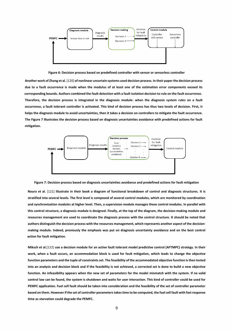
Figure 6: Decision process based on predefined controller with sensor or sensorless controller
Another work of Zhang et al. [120] of nonlinear uncertain systems used decision process. In their paper the decision process
due to a fault occurrence is made when the modulus of at least one of the estimation error components exceed its
corresponding bounds. Authors combined the fault detection with a fault isolation decision to rule on the fault occurrence.
Therefore, the decision process is integrated in the diagnosis module: when the diagnosis system rules on a fault
occurrence, a fault tolerant controller is activated. This kind of decision process has thus two levels of decision. First, it
helps the diagnosis module to avoid uncertainties, then it takes a decision on controllers to mitigate the fault occurrence.
The Figure 7 illustrates the decision process based on diagnosis uncertainties avoidance with predefined actions for fault
mitigation.
Figure 7: Decision process based on diagnosis uncertainties avoidance and predefined actions for fault mitigation
Noura et al. [121] illustrate in their book a diagram of functional breakdown of control and diagnosis structures. It is
stratified into several levels. The first level is composed of several control modules, which are monitored by coordination
and synchronization modules at higher level. Then, a supervision module manages these control modules. In parallel with
this control structure, a diagnosis module is designed. Finally, at the top of the diagram, the decision-making module and
resources management are used to coordinate the diagnosis process with the control structure. It should be noted that
authors distinguish the decision process with the resources management, which represents another aspect of the decision-
making module. Indeed, previously the emphasis was put on diagnosis uncertainty avoidance and on the best control
action for fault mitigation.
Miksch et al.[122] use a decision module for an active fault tolerant model predictive control (AFTMPC) strategy. In their
work, when a fault occurs, an accommodation block is used for fault mitigation, which leads to change the objective
function parameters and the tuple of constraints set. The feasibility of the accommodated objective function is then tested
into an analysis and decision block and if the feasibility is not achieved, a corrected set is done to build a new objective
function. An infeasibility appears when the new set of parameters for the model mismatch with the system. If no valid
control law can be found, the system is shutdown and waits for user interaction. This kind of controller could be used for
PEMFC application. Fuel cell fault should be taken into consideration and the feasibility of the set of controller parameter
based on them. However if the set of controller parameters takes time to be computed, the fuel cell fault with fast response
time as starvation could degrade the PEMFC.

10
As seen above, the decision-making module is the link between the diagnosis module and control module in the case of
FTC strategy. Several kinds of decision module can be implemented and depends on some criteria as the confidence in
diagnosis tool, the fault response time, the study system or the type of the control architecture. In the case of a PEMFC
application, all these criteria must be taken into consideration, and several decision methods should be merged for an
optimal fault mitigation.
B. Active fault tolerant control
Blanke et al. [123] defined two types of AFTC. The first one consists of predefining off-line controller’s parameters (associated
to predefined faults) and switching to the relevant ones when the corresponding fault occurs. This method allows the AFTC
to satisfy the real time constraints and can be quoted as a restructuration of the control law. The second one can be used
when the actualization of the controller’s parameters, as consequence of fault occurrence, enables to maintain the system
stability. In this case, it can be quoted as controller’s parameters reconfiguration. Therefore, an AFTC strategy must respect
the following constraints:
the detection and isolation of any fault have to be done with accuracy, on-line and in real-time,
the restructuration or reconfiguration of the actualized control laws must be made on-line and on real-time,
the fault recovery needs to be done in real-time.
AFTC strategies present some advantages such as taking into account a large set of predefine faults, and providing the system
stability even in degraded mode. It has also some drawbacks such as (i) the AFTC’s implementation is considerably more
complex than the PFTC’s, due to the implementation of an online diagnosis tool, coupled with a decision strategy which
manage a control part, (ii) a high computing time in case of controller reconfiguration, which could have impacts on the real-
time aspects of the implementation, and (iii) the use of a very sensitive diagnosis tool is required to detect and isolate any
fault with accuracy. This sensitive constraint substantially reduces the choice of diagnosis tools.
For a AFTC system, it is possible to consider four sub-systems: a reconfigurable controller; a diagnosis system; a controller
reconfiguration mechanism and a reference set. Blanke et al. [123] and Zhang et al. [92] highlighted some constraints for
AFTC’s application, due to real-time aspect:
controller’s parameters have to be adjusted in real time,
controller have to be automatically restructured using a trial-and-error method,
the whole computational process has to provide a solution, even if there is no optimal one.
It should be noted that these two methods are complementary. As a matter of fact, detection and isolation can be time-
consuming, and lead to a system divergence. In order to prevent any system divergence due to time delay, a PFTC could be
applied to maintain the system stability during the diagnosis process, before an AFTC mechanism takes over for an adequate
control.
In order to present some practical ways to apply fault tolerant control approaches, few examples are given below, highlighting
different applications. For instance, Majdzik et al. [124] presented a fault tolerant control strategy applied on a battery
assembly system. They used a residuals-generation-based diagnosis block in an FTC algorithm: the algorithm consists of a
switch to the suitable control law if a fault is diagnosed. This is an interesting way for fast fault mitigation. Indeed, the switch
means that the control law has been built offline and improves the fault mitigation quickness. In their paper, Zhang et al.

11
[92], developed a closed loop control strategy which tolerates FC system faults by maintaining suitable operating
conditions. This kind of FTC is defined as a combination of fault diagnosis with a control strategy that aims at maintaining
an acceptable performance level during operation in faulty mode. Another example of Maharjan et al. [106] consists in
applying a FTC strategy for a battery energy storage using a cascade PWM (pulse-width-modulation) converter. Their goal
is to provide a continuous operation of battery units, even if the converter-cell or the battery unit is in faulty condition. Li
et al. [57] propose in their paper an architecture based on a diagnosis system and three sliding mode controllers (SMC). The
fault tolerant control strategy is applied to an electric vehicle in order to control its longitudinal speed, lateral speed and the
trajectory deviation. They use for their study an active fault tolerant control.
Several papers dealing with fault tolerant control also exist in many other fields, such as in transport and energy storage
[107]–[109] or in electronic manufacturing services [112]. Miksch et al. [122] use an active fault tolerant model predictive
control (AFTMPC) for a real time implementation. The simulated fault are: actuator faults like saturation; freezing and total
loss. In the case of a fault occurrence, an accommodation or reconfiguration process can be activated. They define the
accommodation as the change of the control law for a fault mitigation. The reconfiguration consists of a change of the
control loop and the control law. Indeed, accommodation and reconfiguration are major topics for fault tolerant control
strategies. These two points need to be further detailed in the case of PEMFC applications because faulty conditions have
large span action. Another research on FTC has been done by Li et al. [125] for nonlinear Lipschitz stochastic distribution
systems. They highlight the problem of the diagnosis system accuracy. Indeed they proposed, in addition to the diagnosis
system, a fault estimation (FE). Authors investigated some possible approaches as the sliding mode observer technique
(SMO), adaptive approach or unknown input observer method. They underlines a big issue of diagnosis systems. Indeed,
the compromise between the speed, reliability and genericity of the diagnosis tool could provoke a decrease of diagnosis
result accuracy. The type of faults which can occur in the system is also a problem for fault diagnosis accuracy. For this
reason, in FTC strategies, it is generally useful to consider an additional module for diagnosis results filtering. Badihi et al.
also used a AFTC strategies [126] applied in an offshore wind farm. For their study they used a fault detection and diagnosis
(FDD) system in a fault tolerant control strategy. Any faulty event can be analyzed by the FDD from the system powers and
generate an information about any faulty condition. An automatic signal correction and an accommodation are set on the
faulty turbine.
Shahbazi et al. [127] study a six-leg back-to-back fault tolerant converter. In their system, fault can occur in each leg and are
diagnosed by comparing the estimated and measured pole voltages. They assume that a reconfiguration of the control
strategy is enough to ensure a minimum performance. The reconfiguration mechanism consists of a bidirectional switch to
change the converter structure from six-leg to five-leg. This paper assumes that an investigation of the possible degraded
mode has been made. Indeed, authors highlight the possibility to consider the system to operate with minimal
performance.
In the medical domain, Su et al. [128] study microfluidic biochips. They used this technology for patient health monitoring
and for this reason, its reliability have to be ensured. In order to do so, a fault tolerant strategy is applied on the biochip to
keep its functionalities even in faulty conditions. In the article, authors considered a uniform failure probability to estimate
fault tolerant capacity of the biochip. This kind of applications warns about the system reliability and the necessity to keep
performance during faulty conditions. Redundancies or high diagnosis system performance can be used to avoid
degradations.

12
Guilbert et al. [13], [15] applied a FTC strategy to the DC/DC converter of a PEMFC. The considered converter is made with 3
legs. An electronic control unit (ECU) is used as diagnosis system to detect any faulty condition. In this case, the FTC
mechanism consists in degrading the converter performance to bring back the PEMFC to optimum operating conditions.
Fukuhara et al. [129] worked on an open cathode fuel cell. They stated that anodic flooding, which causes carbon corrosion,
is one of the recurrent fault. For this reason, a work on the exhaust gas management is done to improve the time delay
between two purges. The goal of this fault tolerant strategy is to mitigate the effect of the water for the extension of the fuel
cell lifespan. They also develop a physics-based anodic chamber model, in order to generate residuals to diagnose a flooding
in the anode chamber. Here, authors underline that it exists some permanent processes that always generate a fault. In
this case, a bad water management can increase the water accumulation and finally degrade the system.
One of the few research on (A)FTC applied to PEMFC, have been done by Lebreton et al. [14] [115] dealing with water
management and air feeding system. They used a neural network to compute on-line the new PID self-tuning parameter
values to recover the detected fault. In their study, the FTC strategy computes on-line and in real-time a new oxygen
stoichiometry value adapted to the fault occurrence. However, this kind of fault mitigation is relevant if authors consider
the occurrence frequency of the same fault. The occurrence frequency is the number of appearance of a fault on a given
time. Indeed, a decision which is only based on stoichiometry can mitigate the fault but it has no influence on the
occurrence frequency. For this reason, the decision tool should be designed to include the fault occurrence frequency. Wu
et al. [130] also performed a FTC strategy applied to a PEMFC. They used a diagnosis method based on residual generation
with a back propagation neural network model, reconfiguration mechanism and three adjustable nonlinear controllers. The
diagnosis system is designed by the generation and analysis of residuals between the real system data and a back-propagation
neural network to detect a flooding, drying out or normal operating conditions. Their controller consists of feedback
linearization and is used to change the voltage and pressure difference depending on normal or faulty conditions. Some
researchers applied a FTC strategy on auxiliaries’ faults of PEMFC systems. In their paper, Nouri et al. [131] aim to improve
the photovoltaic system efficiency by proposing a fault tolerant control using diagnosis tools and a reconfiguration
mechanism on a multilevel dc-dc converter. In their study, when a fault is detected, a flag variable is raised, then a
reconfiguration circuit is activated for a fault recovery. In the case of less complex systems than fuel cells, the processes are
well known. For this reason and because fault behavior is known, offline configuration is the best methodology for fault
mitigation.
The table A3 gives a summary of papers dealing with fault tolerant control.
There are many possible combinations of control laws with diagnosis tools and decision blocs to develop a FTC strategy. The
best one strongly depends on the constraints imposed by the studied system and the considered faults. The FTC strategy has
to detect, isolate and compute the adapted control law to recover the fault before any degradation occurs.
V. Discussion
There are many possible combinations of control laws with diagnosis tools and decision blocks to develop a FTC strategy.
The best one strongly depends on the constraints imposed by the studied system and the considered faults. The FTC
strategy has to detect, isolate and compute the adapted control law to recover the fault before any degradation occurs.
Yet, for the complex PEMFC systems, each fault has a specific response time and influences differently the performance.
The cell exposure time to the fault is a key factor that determines the capability to recover performances, for the major
part of the faults. Therefore, defining online, real time corrective actions is crucial for these systems. Because a sole

13
corrective action cannot be considered for all possible faults, and an efficient correction should be adapted to the nature
of the identified fault, a suitable control strategy has to be applied for each fault and, in some cases, each level of faults’
severity (magnitude). This is why a proper diagnosis of the fault is needed prior to define the involved parameters, the
adapted correction actions and the suitable control.
The existing publications on fuel cell control address two main objectives: either minimizing the cost (fuel consumption)
and/or optimizing the performance. Very few works consider fault occurrence and therefore fuel cell state of health (SoH)
and lifetime, which are real issues for fuel cell systems deployment. This could be explained by the difficulty to develop
online, real-time, sensitive and accurate enough diagnostics, combined with online, real-time control laws reconfiguration.
Besides, the high interdependence of the complex fuel cell parameters makes the system stabilization very sensitive to
any post-diagnostic adjustment of the controller parameters.
In a FTC strategy, the decision-making module is the link between the diagnosis module and control module. Several kinds
of decision-making modules can be implemented taking into account criteria such as the confidence in diagnosis tool, the
fault response time, the studied system or the type of the control architecture. In the case of a PEMFC application, several
decision methods should be merged for an optimal fault mitigation and besides all these criteria, two important
considerations should be taken into account, namely the occurrence frequency of the same fault and the magnitude of the
fault. The occurrence frequency is the number of appearance of a fault on a given time. For instance, a decision which is
only based on stoichiometry can mitigate the water management related fault but it will have a limited influence on the
occurrence frequency. On the other hand, the major part of the faults appears gradually, therefore, adapted decision to
the fault magnitude can be chosen. However, it is far from easy to determine a fault magnitude with the existing diagnosis
tool, and this is the reason why, fault magnitude is hardly considered in the existing decision strategies.
Therefore, a fault mitigation has to be done with three considerations: the fault has to be mitigated as fast as possible
(stoichiometry action in case of FTC for water management for instance); the fault magnitude has to be known to take the
best decisions (that means the use of an accurate online diagnosis tool); the decision tool has to decrease the fault
occurrence frequency.
VI. ConclusionLow reliability in PEM fuel cells remains one of the major obstacles to a large commercialization. For this reason, a fault
mitigation strategy, also called a FTC must be set up. This paper reviews the possible fault tolerant control FTC strategies and
discusses their use in PEMFCs systems. The different steps of a FTC strategy, namely diagnostics, decision and control are
given. If many studies have been already made about control of a fuel cell through auxiliaries, the literature does not provide a
lot of information about FTC strategies applied to PEMFC systems, which can be considered as a milestone to increase the
reliability of PEMFC systems. Indeed, several faults occur in PEMFC and each of them affects it differently and degrades it
more or less rapidly. For this reason an accurate online fault diagnosis remains a major issue for FTC strategies. Actually, the
more accurate the diagnosis tool is, the more efficient the control action is. In addition an additional module is needed: a
decision-making module. It allows avoiding the diagnosis uncertainties and taking decision about the best control strategies for
optimal fault mitigation.
Acknowledgements
This project is supported by the Région Bourgogne Franche-Comté, the Région Réunion, and the Labex ACTION program
(contract ANR-11-LABX-0001-01).

14
APPENDIX A
A1: a summary of papers dealing with fault diagnosis
Auteurs Description of the diagnosis approach Faults Variables & parameters
Zheng et al. [94] Fuzzy logic and classification, data acquisition
with spectroscopy method by electrochemical
impedance.
- Water management
issues
- air starvation
- Anodic relative humidity
- Cathodic relative humidity
- Hydrogen stoichiometry
- Air stoichiometry - Stack temperature
de Beer et al. [32] Using EIS through rapid injection of in-signals
across the membrane
Flooding
- Drying
Signal variation between 1Hz and 1kHz
Cathode Stoichiometry 2.4
Anode Stoichiometry 4
Chevalier et al. [30] 2D modeling of the impedance spectrum (AC) of
a PEMFC
Flooding
- Drying
- Thickness of cells 0.1m
- Width cathode channels 1.10-3m
- GDL thickness 300 .10-6m
- Membrane thickness 89.10-6m
- Membrane conductivity 0.45S.m-1
- Anode current exchanged 80 A m²
- Cathode current exchanged 6.8.10-2 A.m-2
- Anode charge transfer anode 1
- Cathode charge transfer 0.583
- Porosity GDL 0.43
- Double layer capacity 240 F.m-²
- Temperature 313 K
- Absolute pressure 1 bar
- Air flow 0.4 L.min-1
- H2 flow 0.16 Lmin-1
- Air relative humidity 100%
- Hydrogen relative humidity 100%
Damour et al. [31] Empirical mode decomposition method Flooding
- Drying
- Fuel cell temperature 70°C
- Anode/cathode pressure 300kPa
- O2 and H2 relative humidity 80%
- Saturated H2 stoichiometry 2
- Saturated O2 stoichiometry 5
Hua et al. [49] statistical methods such as the Signed Directed
Graph Method
No information - Vehicle mass 1.4672.10^4 kg
- Vehicle frontal area 7.5 m²
- Drag coefficient 0.7
- Rolling resistance coefficient 1.8.10-2
- Mechanical efficiency 95%
- Masse factor 1.1
- PEM fuel cell rated power 80 kW
- DC/DC rated power 80 kW
- Ni-MH battery rated capacity 80 kW
- Electric motor peak power 150 kW
- Electric motor peak torque 1.121.103 N m
- Electric motor rated power 100 kW
- Electric motor maximal rotational speed 6.103 rpm
Steiner et al. [80] &
Pahon et al. [69]
[50]
stack voltage signa processingl by wavelet
transform (WT)
Flooding
- Drying
Current, individual cell voltage
Extraction of the « feature vector » from the WT analyze to get a
corresponding parameter set Benouiouaa et al.
[23]
Extracting singularities from the stack voltage
signal using the method of WT
- Anodic & cathodic starvation
- Cooling system fault
- CO poisoning
- Air & hydrogen stoichiometry
- Pressure
- Temperature
- Presence of CO (ppm) Banerjee et al. [20] Using of two-phase pressure drop multiplier as a
diagnosis tool for characterizing PEM fuel cell
performance
Flooding
- Drying
- Temperature (30 to 60°C)
- Cathodic relative humidity (0 to 95%)
- Current density (0.4 to 0.8 A/cm²) Ma et al. [108] Using the pressure drop as a diagnosis tool Flooding
- Drying
- Current density
- Humidification and cell temperature 60°C
- O2 flow speed in channels
- Anode et cathode pressure 0.1 Mpa(AFTC)- H2 flow rate 87
ml.min-1

15
Li et al. [61] Data clustering methodologies (Fisher
Discriminant Analysis & Support Vector
Machine).
Flooding - Drying - Cell area 100 cm²
- Cells number 20
- Flow field structure serpentine
- Nominal output power 500w
- Nominal operating temperature 40°C
- Operating temperature region 20-65°C
- Maximum operating pressures 1.5 bar
- Anode stoichiometry 2
- Cathode stoichiometry 4
Riascos et al. [74] Bayesian network. A mathematical model for a
500 W stack
- Air fan fault
- Refrigeration system fault
- Growth of the fuel crossover
- Hydrogen pressure fault
- Cells number 32
- Membrane active area 64 cm2
- Membrane thickness 178 µm
- O2 pressures 0.2095 atm
- H2 pressures 1 atm
- Contact resistance to electron flows 0.003 ohm
- Fuel crossover and internal loss current 3 mA cm2
- O2 & H2 pressure
- Maximum electrical current density 0.469 A cm2
Shao et al. [78] Neural networks - Stack cooling system
- Air delivery system
- Hydrogen delivery system
- Stack power 500W
- Number of cells 36
- Environmental T 5-30°C
- Unit dimensions : 22.5*12.5*17.5 cm3
- Weight: 2.5 kg
- Reference potential E0 44.15 V
- limit of current density 0.468 A.cm-2
Steiner et al. [89] Neural networks Flooding - Drying - Cells number 20
- Total active area 100 cm²
- Temperature range 25-65°C
- Thickness 25 µm
- Platinum load (anode & cathode) 0.4 mg.cm-2
- Gas diffusion layer thickness 420 µm
- Porosity 84%
- Flow channel (geometry) used: serpentine
- Reactant stoichiometry ratio (anode/cathode): 2/4
- Compressive force/torque used to assemble the stack 8 Nm
- Gas purity: Hydrogen with max 8 ppm impurity (<3 ppm H2O,
<1 ppm O2, <0.5 CO + CO2, <5 ppm N2)
- Ion resistivity of DIW used for humidification of reactants
Deionized with conductivity < 10 μS cm−1
A2: a summary of papers which dealing with PEMFC control
Authors Description/Advantages Applications Variables/Parameters
Wang et al. [2] Robust Control based on H infinite norm
to regulate the hydrogen flow rate.
PEMFC power supply management.
2 stacks of 3kw
1 battery Li-Fe
- Cells number 80
- Max power supply DC 3.2 kw
- Input voltage 24 VDC
- Output voltage 42-80 VDC
- Weight 40 kg
- Fuel input temperature -15 to 55°C
- Fuel input pressure 0.36 bar
- Air input temperature 10 to 50°C

16
Wang et al. [3], [5] Discussion of several power management
strategies on a PEM fuel cell using a
robust control based on H infinite norm.
Fuel cell of 500 W used in a car For the [3]
- Fuel cell voltage 24-37 V DC
- Nominal power 500W
- Efficiency for 500W >47%
- Dimensions (cm^3) 11.7*11.3*25
For [5]
- Cell’s number 37
- Surface 47 cm²
- Max power supply <500W
- Output voltage 22-37V
- Efficiency for 500W >47%
- Dimensions (cm^3) 11.7*11.3*25
- Weight 2.4 kg
- Stack temperature <55°C
Wang et al. [103] Multivariable robust control of a proton
exchange membrane fuel cell system
The PEMFC is modeled as a MIMO system - Number of cells 15
- Active area 50 cm² on each
- Maximum efficiency of the fuel cell stack
is 37% under dry H2/air and
humidification-free
Control variables are:
- H2 flow rate
- Air flow rate
- Pump voltage
Hilairet et al. [99] Online humidification diagnosis of a
PEMFC using a static DC–DC converter
The system is modeled with a Randles
equivalent circuit
PEMFC’s stack of 500W. - Number of cells 23
- Active Area 100cm²
- Activation losses 8.3V
- Double layer capacitor 20mF
- Membrane resistivity 40 mOhm
- Current ripple 3.5 peak-to-peak
- Series inductor 35 nH
Zhiyu et al. [105] Optimal control of the air-cooling and self
- humidification by using a predictive
control negative feedback
Stack of 56 cell and a power supply of 2
kW
- Output current between 0 et 75A
- Max temperature 75 °C
- Hydrogen pressure 0.36 bar
- Output voltage between 28 V et 56 V
Tabanjat et al. [102] Control of the water temperature at the
electrolyzer input to improve the
efficiency of the PEMFC. Using a PI
controller combined with a correction
based on fuzzy logic
Application on a PEMFC – electrolyzer of
59 kW powered by a photovoltaic
generator - through a " boost- converter "
- Stack current 300 A
- Cell’s number 90
- Hydrogen pressure 1.09*105 Pa
- Oxygen pressure 105 Pa
- Surface 0.06 m²
- Active area 0.0016 m²
-Membrane thickness 130*10-6 µm
SID et al. [6] Minimizing the consumption of hydrogen
to maintain the battery's charge state.
Using the principle of minimum
Pontryagin.
- Number of battery element 30
- Mass of a battery element 3.76 kg
- Nominal capacity of the battery 12Ah
- Max state of charge 90%
- Min state of charge 40%
- Max power of the fuel cell 30 kW
- Min power of the fuel cell 600 W
Garcia-Gabin et al. [10] Describes a method of control sliding
mode based on a SISO model. The
purpose of control here is to act in oxygen
starvation.
Ballard’s PEMFC stack of 1.2kw. The stack
is composed of 46 cells and each of them
with an 110 cm² membrane.
Controller parameters:
- Sliding surface
- Tuning parameters of the sliding surface
- Tuning parameters of the controller
- Times constants
Stack’s parameters:
- Oxygen excess ratio
- Stack current
- Air mass flows from compressor
- Compressor voltage in %

17
Kunusch et al. [12] Control by sliding mode on a PEM fuel cell
system. Stability is improved by a " Super
Twisting " algorithm
Applied to a 75kw PAC system and
powered by a 14kw compressor.
Integration on an electric vehicle
- Stack temperature
- Cathode volume
- Atmospheric pressure
- Ambient temperature
- Electric motor resistance
- Compressor diameter
- Motor inertia
Li et al. [11] Adaptative control on a fuel cell by using
the backstepping technique.
- Control is done without linearization
- Controller is easily implemented on the
practical application
- Stability of the closed-loop system
- Using a neural network to approximate
the unknown non-affine function
The controller is applied on a 75 kW PEM
fuel cell system.
The model only includes the air flow
model
States of the used model:
- cathode pressure
- air pressure in the supply manifold
- the rotational speed of the compressor
Benchouia et al. [97] Adaptative fuzzy logic controller for
PEMFC
The controller is applied on PEM fuel cell
system of 4 cells
Controlled variable: hydrogen molar flow.
- Temperature 298.15 K
- E0 1.229V
- Membrane resistivity 0.126 S
- Limit current density 0.01496 A.cm-²
Matraji et al. [16] Robust control of the PEM fuel cell air-
feed system via sub-optimal second order
sliding mode
The objective is to maintain optimum net
power output by regulating the oxygen
excess ratio in its operating range,
through the air compressor.
On a Hardware-In-Loop test bench with a
twin screw compressor and real time fuel
cell emulation system.
- Number of cells 90
- Fuel cell temperature 353.15 K
- Compressor inertia 671.9 x 10⁻⁵ kg m²
- Motor friction 0.00136 V.(rad.s-1)-1
- Motor constant 0.31 N m.A-1
Cathode volume 0.0015 m3
- Supply manifold volume 0.003 m3
- Cathode inlet orifice constant 0.3629 x
10-5 kg (Pa s)
- Cathode outlet orifice constant 0.76 x
10-4 kg(Pa s)
A3: a summary of some papers which uses FTC strategies
FTC strategies Description Architecture Variables/Parameters
Guilbert et al. [13] Fault tolerant control applied to the
DC/DC converter of a PEMFC.
The study is made on an Interleaved
Boost Converter with 3 legs
The diagnosis tool is a software which
discusses with the Electric Control Unit
(ECU) of the PEMFC. Here FTC consists to
degrading converter performances .in
order to bring back the PEMFC in an
optimum operating condition
- PEMFC rated power 1kW
- PEMFC rated current 42 A
- PEMFC voltage range 25-32V
- Inductor value 120µH
- DC bus voltage 100V
- Switching frequency 20 kHz
- Duty cycle range 0.68-0.74
Guilbert et al. [15]
FTC method which involve the change of
the Pulse-width modulation gate control
signal. The method is applied to the
electric vehicle using a PEMFC stack.
IBC topology (Interleaved DC / DC Boost
Converter). Interest is compensation to
the extent that if a branch is in fault,
another branch takes over.
- PEMFC power 1kw
- Current 42A
- Ripple current 2A
- Voltage span 25-32V
- Inductance 150µH
- Bus DC voltage 100V
- Switching frequency 20kHz

18
Lebreton et al. [14] Method allowing the detection of PEM
fuel cell faults related to water
management. A combined neural
network in a self-tuning PID controller is
used.
The used architecture is based on a
diagnosis system into neural networks
and a self-tuning controller for a
reconfiguration of the controller
parameters.
- PID parameters Kc, Ti, Td
- Necessary parameters for the number
of I/O
- A parameter for the trajectory tracking
error
Li et al. [57] - Control of the longitudinal speed
- Control of the lateral speed
Control of the trajectory deviation rate
on the road
- Restructuration controller
Architecture based on a diagnosis system
and three sliding mode controllers. FTC
applied to an electric vehicle.
-Vehicle mass
- Widths of the front and rear of the
vehicle
- Longitudinal stiffness of the tires
- Moment of inertia of the vehicle around
the axis of deflection
- Radius of the wheel
- Moment of inertia of the wheel
- Reducing factor adhesion of the wheel
Aouzellag et al. [4] Energy management and FTC strategies
for fuel cell/ultracapacitor hybrid electric
vehicles
Speed regulation by Sliding Mode Control
(SMC)
Bus voltage regulation and UC converter
control by PI controller.
The diagnosis tool is based on an
algorithm
- Vehicle mass 1300kg
- Rolling resistance force constant 0.01
s².m-²
- Air density 1.2 kg.m3
- Frontal surface area of the vehicle 2.6
m²
- Tire radius 0.32m
- Aerodynamic drag coefficient 0.3
- Acceleration due to the gravity 9.8 m.s-²
Puig et al. [101] Fault-tolerant explicit MPC of PEM fuel
cells
The controller is pre-determined offline.
It allows changing in real-time controller
parameters without recomputing the
MPC controller or having a bank of pre-
computed MPC controller.
The simulated fault is the starvation.
- Control action on oxygen excess ratio
- Number of cells 381
- Membrane Nafion 117
- Active area 280 cm²
- Nominal stack voltage 45 V
- Nominal stack current 191A
- Maximum power 75 kW
Wu et al. [130] Active fault tolerant control used to
recover flooding and/or drying out. The
Strategy is applied on a PEMFC.
They used a back-propagation neural
network (BPNN) model to compute
residuals to rule on normal or faulty
conditions. Three backup controllers are
used to regulate the pressure difference
and PEMFC voltage. This regulation
allows to change the set point when a
fault occurs. The reconfiguration
mechanism consist of a switch between
the three available controllers.
Inputs of BPNN model:
- Injected water flowrate in humidifier
- Water flowrate of the coolant
- Anode inlet pressure
- Humidifier inlet pressure
- The load current
Wang et al.[132] Fault tolerant control on a civil aircraft.
The reconfiguration mechanism is used in
this case.
Structures are predetermined. The
principle is to " switch" on a controller
with appropriate parameters to changes
the physical behavior of the system
No information

19
REFERENCES
[1] M. Wakizoe, O. A. Velev, and S. Srinivasan, “Analysis of proton exchange membrane fuel cell performance with
alternate membranes,” Electrochim. Acta, vol. 40, no. 3, pp. 335–344, Feb. 1995.
[2] F.-C. Wang, P.-C. Kuo, and H.-J. Chen, “Control design and power management of a stationary PEMFC hybrid power
system,” Int. J. Hydrogen Energy, vol. 38, no. 14, pp. 5845–5856, 2013.
[3] F.-C. Wang, C.-Y. Gao, and S.-C. Li, “Impacts of power management on a PEMFC electric vehicle,” Int. J. Hydrogen
Energy, vol. 39, no. 30, pp. 17336–17346, 2014.
[4] H. Aouzellag, K. Ghedamsi, and D. Aouzellag, “Energy management and fault tolerant control strategies for fuel
cell/ultra-capacitor hybrid electric vehicles to enhance autonomy, efficiency and life time of the fuel cell system,”
Int. J. Hydrogen Energy, vol. 40, no. 22, pp. 7204–7213, 2015.
[5] F.-C. Wang and Y.-S. Chiang, “Design and control of a PEMFC powered electric wheelchair,” Int. J. Hydrogen Energy,
vol. 37, no. 15, pp. 11299–11307, 2012.
[6] M. N. SID, M. BECHERIF, K. MAROUANI, and H. ALLOUI, “Gestion de líÈnergie díun systËme hybride pile
‡combustible/batterie basÈe sur la commandeoptimale,” Mediterr. J. Model. andSimulation, pp. 010–024, 2015.
[7] C. A. Ramos-Paja, A. Romero, R. Giral, J. Calvente, and L. Martinez-Salamero, “Mathematical analysis of hybrid
topologies efficiency for PEM fuel cell power systems design,” Int. J. Electr. Power Energy Syst., vol. 32, no. 9, pp.
1049–1061, 2010.
[8] L. Perrette, S. Chelhaoui, and D. Corgier, “Safety evaluation of a PEMFC bus,” 2003.
[9] M. Gerbec, V. Jovan, and J. Petrovčič, “Operational and safety analyses of a commercial PEMFC system,” Int. J.
Hydrogen Energy, vol. 33, no. 15, pp. 4147–4160, 2008.
[10] W. Garcia-Gabin, F. Dorado, and C. Bordons, “Real-time implementation of a sliding mode controller for air supply
on a PEM fuel cell,” J. Process Control, vol. 20, no. 3, pp. 325–336, 2010.
[11] P. Li, J. Chen, T. Cai, and B. Zhang, Adaptive control of air delivery system for PEM fuel cell using backstepping. IEEE,
2011.
[12] C. Kunusch, P. F. Puleston, M. A. Mayosky, and J. Riera, “Sliding Mode Strategy for PEM Fuel Cells Stacks Breathing
Control Using a Super-Twisting Algorithm,” IEEE Trans. Control Syst. Technol., vol. 17, no. 1, pp. 167–174, Jan. 2009.
[13] D. Guilbert, A. Gaillard, A. N’Diaye, and A. Djerdir, “Fault-tolerant control for PEMFC and its DC/DC converter,” in
2015 5th International Youth Conference on Energy (IYCE), 2015, pp. 1–6.
[14] C. Lebreton et al., “Fault Tolerant Control Strategy applied to PEMFC water management,” Int. J. Hydrogen Energy,
vol. 40, no. 33, pp. 10636–10646, 2015.
[15] D. Guilbert, M. Guarisco, A. Gaillard, A. N’Diaye, and A. Djerdir, “FPGA based fault-tolerant control on an
interleaved DC/DC boost converter for fuel cell electric vehicle applications,” Int. J. Hydrogen Energy, vol. 40, no.
45, pp. 15815–15822, 2015.
[16] I. Matraji, S. Laghrouche, S. Jemei, and M. Wack, “Robust control of the PEM fuel cell air-feed system via sub-
optimal second order sliding mode,” Appl. Energy, vol. 104, pp. 945–957, 2013.
[17] M. Jouin, R. Gouriveau, D. Hissel, M.-C. Péra, and N. Zerhouni, “Prognostics and Health Management of PEMFC –
State of the art and remaining challenges,” Int. J. Hydrogen Energy, vol. 38, no. 35, pp. 15307–15317, 2013.
[18] J. C. Amphlett, R. M. Baumert, R. F. Mann, B. A. Peppley, P. R. Roberge, and T. J. Harris, “Performance Modeling of
the Ballard Mark IV Solid Polymer Electrolyte Fuel Cell,” J. Electrochem. Soc., vol. 142, no. 1, p. 1, 1995.
[19] S. Asghari, A. Mokmeli, and M. Samavati, “Study of PEM fuel cell performance by electrochemical impedance

20
spectroscopy,” Int. J. Hydrogen Energy, vol. 35, no. 17, pp. 9283–9290, 2010.
[20] R. Banerjee, D. Howe, V. Mejia, and S. G. Kandlikar, “Experimental validation of two-phase pressure drop multiplier
as a diagnostic tool for characterizing PEM fuel cell performance,” Int. J. Hydrogen Energy, vol. 39, no. 31, pp.
17791–17801, 2014.
[21] F. Barbir, H. Gorgun, and X. Wang, “Relationship between pressure drop and cell resistance as a diagnostic tool for
PEM fuel cells,” J. Power Sources, vol. 141, no. 1, pp. 96–101, 2005.
[22] F. Barbir, PEM Fuel Cells: Theory and Practice, Elsevier. London: Academic Press Inc, 2005.
[23] D. Benouioua, D. Candusso, F. Harel, and L. Oukhellou, “PEMFC stack voltage singularity measurement and fault
classification,” Int. J. Hydrogen Energy, vol. 39, no. 36, pp. 21631–21637, 2014.
[24] O. Bethoux, M. Hilairet, and T. Azib, “A new on-line state-of-health monitoring technique dedicated to PEM fuel
cell,” in 2009 35th Annual Conference of IEEE Industrial Electronics, 2009, pp. 2745–2750.
[25] L. Boulon, K. Agbossou, D. Hissel, P. Sicard, A. Bouscayrol, and M.-C. Péra, “A macroscopic PEM fuel cell model
including water phenomena for vehicle simulation,” Renew. Energy, vol. 46, pp. 81–91, 2012.
[26] L. Boulon, D. Hissel, A. Bouscayrol, and M. C. Péra, “From modeling to control of a PEM fuel cell using energetic
macroscopic representation,” IEEE Trans. Ind. Electron., vol. 57, no. 6, pp. 1882–1891, 2010.
[27] C. Cadet, S. Jemeï, F. Druart, and D. Hissel, “Diagnostic tools for PEMFCs: from conception to implementation,” Int.
J. Hydrogen Energy, vol. 39, no. 20, pp. 10613–10626, 2014.
[28] D. Candusso and J.-M. Kauffmann, “Piles à combustible PEMFC et SOFC Description et gestion du système Raynal
GLISES,” 2007.
[29] J. Chen and B. Zhou, “Diagnosis of PEM fuel cell stack dynamic behaviors,” J. Power Sources, vol. 177, no. 1, pp. 83–
95, 2008.
[30] S. Chevalier, D. Trichet, B. Auvity, J. C. Olivier, C. Josset, and M. Machmoum, “Multiphysics DC and AC models of a
PEMFC for the detection of degraded cell parameters,” Int. J. Hydrogen Energy, vol. 38, no. 26, pp. 11609–11618,
2013.
[31] C. Damour, M. Benne, B. Grondin-Perez, M. Bessafi, D. Hissel, and J.-P. Chabriat, “Polymer electrolyte membrane
fuel cell fault diagnosis based on empirical mode decomposition,” J. Power Sources, vol. 299, pp. 596–603, 2015.
[32] C. de Beer, P. Barendse, P. Pillay, B. Bullecks, and R. Rengaswamy, “Online fault diagnostics and impedance
signature mapping of High Temperature PEM fuel cells using rapid small signal injection,” in IECON 2013 - 39th
Annual Conference of the IEEE Industrial Electronics Society, 2013, pp. 1798–1803.
[33] P. Deevanhxay, T. Sasabe, S. Tsushima, and S. Hirai, “In situ diagnostic of liquid water distribution in cathode
catalyst layer in an operating PEMFC by high-resolution soft X-ray radiography,” 2012.
[34] U. Departement et al., “‘ Electrochemical Impedance Spectroscopy for the on-board diagnosis of PEMFC via on-line
identification of Equivalent Circuit Model parameters ,’” 2013.
[35] Elodie and Lechartier, “Modèle statique d’une PEMFC en vue d’une application au pronostic,” pp. 1–8, 2014.
[36] T. Escobet et al., “Model-based fault diagnosis in PEM fuel cell systems,” J. Power Sources, vol. 192, no. 1, pp. 216–
223, 2009.
[37] K. Ettihir, L. Boulon, M. Becherif, K. Agbossou, and H. S. Ramadan, “Online identification of semi-empirical model
parameters for PEMFCs,” Int. J. Hydrogen Energy, vol. 39, no. 36, pp. 21165–21176, 2014.
[38] N. Fouquet, C. Doulet, C. Nouillant, G. Dauphin-Tanguy, and B. Ould-Bouamama, “Model based PEM fuel cell state-
of-health monitoring via ac impedance measurements,” J. Power Sources, vol. 159, no. 2, pp. 905–913, 2006.
[39] M. Gerard, J.-P. Poirot-Crouvezier, D. Hissel, and M.-C. Péra, “Ripple Current Effects on PEMFC Aging Test by
Experimental and Modeling,” J. Fuel Cell Sci. Technol., vol. 8, no. 2, p. 21004, 2011.

21
[40] M. Gerard, J.-P. Poirot-Crouvezier, D. Hissel, and M.-C. Pera, “Oxygen starvation analysis during air feeding faults in
PEMFC,” Int. J. Hydrogen Energy, vol. 35, no. 22, pp. 12295–12307, 2010.
[41] M. Gholami, H. Esen, H. Schioler, and J. Stoustrup, “A Fault-Tolerant Control Architecture for Different Battery
Topologies in Electrified Vehicles.”
[42] S. Giurgea, R. Tirnovan, D. Hissel, and R. Outbib, “An analysis of fluidic voltage statistical correlation for a diagnosis
of PEM fuel cell flooding,” Int. J. Hydrogen Energy, vol. 38, no. 11, pp. 4689–4696, 2013.
[43] D. Guilbert, A. Gaillard, A. Mohammadi, A. N’Diaye, and A. Djerdir, “Investigation of the interactions between
proton exchange membrane fuel cell and interleaved DC/DC boost converter in case of power switch faults,” Int. J.
Hydrogen Energy, vol. 40, no. 1, pp. 519–537, 2015.
[44] F. Harel et al., “Electrochemical characterisation of fuel cell stack during cold start,” Eur. Phys. Journal, Appl. Phys.,
vol. 54, no. 2, 2011.
[45] F. He, H. Wang, and L. Ma, “Experimental demonstration of active thermal control of a battery module consisting
of multiple Li-ion cells,” Int. J. Heat Mass Transf., vol. 91, pp. 630–639, 2015.
[46] M. Hinaje, I. Sadli, J.-P. Martin, P. Thounthong, S. Raël, and B. Davat, “Online humidification diagnosis of a PEMFC
using a static DC–DC converter,” Int. J. Hydrogen Energy, vol. 34, no. 6, pp. 2718–2723, 2009.
[47] D. Hissel, M. . Péra, and J. . Kauffmann, “Diagnosis of automotive fuel cell power generators,” J. Power Sources, vol.
128, no. 2, pp. 239–246, 2004.
[48] J. Hua, J. Li, M. Ouyang, L. Lu, and L. Xu, “Proton exchange membrane fuel cell system diagnosis based on the
multivariate statistical method,” Int. J. Hydrogen Energy, vol. 36, no. 16, pp. 9896–9905, 2011.
[49] J. Hua, L. Lu, M. Ouyang, J. Li, and L. Xu, “Proton exchange membrane fuel cell system diagnosis based on the
signed directed graph method,” J. Power Sources, vol. 196, no. 14, pp. 5881–5888, 2011.
[50] M. Ibrahim et al., “Signal-Based Diagnostics by Wavelet Transform for Proton Exchange Membrane Fuel Cell,”
Energy Procedia, vol. 74, pp. 1508–1516, 2015.
[51] M. Ibrahim, S. Jemei, G. Wimmer, N. Y. Steiner, C. C. Kokonendji, and D. Hissel, “Selection of mother wavelet and
decomposition level for energy management in electrical vehicles including a fuel cell,” Int. J. Hydrogen Energy, vol.
40, no. 45, pp. 15823–15833, 2015.
[52] S. Jeme and H. A. L. Id, “Modélisation d ’ une pile à combustible de type PEM par réseaux de neurones,” 2004.
[53] M. Jouin et al., “Estimating the end-of-life of PEM fuel cells: Guidelines and metrics,” Appl. Energy, vol. 177, pp.
87–97, Sep. 2016.
[54] S. D. Knights, K. M. Colbow, J. St-Pierre, and D. P. Wilkinson, “Aging mechanisms and lifetime of PEFC and DMFC,” J.
Power Sources, vol. 127, no. 1, pp. 127–134, 2004.
[55] B. Legros, P. X. Thivel, F. Druart, Y. Bultel, and R. Nogueira, “Diagnosis and modelling of proton-exchange-
membrane fuel cell via electrochemical-impedance-spectroscopy and Acoustic-Emission measurements,” in 2009
8th International Symposium on Advanced Electromechanical Motion Systems & Electric Drives Joint Symposium,
2009, pp. 1–6.
[56] B. Legros, P.-X. Thivel, Y. Bultel, and R. P. Nogueira, “First results on PEMFC diagnosis by electrochemical noise,”
2011.
[57] B. Li, H. Du, and W. Li, “Fault-tolerant control of electric vehicles with in-wheel motors using actuator-grouping
sliding mode controllers,” Mech. Syst. Signal Process., vol. 72, pp. 462–485, 2016.
[58] H. Li et al., “A review of water flooding issues in the proton exchange membrane fuel cell,” J. Power Sources, vol.
178, no. 1, pp. 103–117, 2008.
[59] Z. Li, S. Giurgea, R. Outbib, and D. Hissel, “Online Diagnosis of PEMFC by Combining Support Vector Machine and

22
Fluidic Model,” Fuel Cells, vol. 14, no. 3, pp. 448–456, Jun. 2014.
[60] Z. Li, R. Outbib, S. Giurgea, D. Hissel, and Y. Li, “Fault detection and isolation for Polymer Electrolyte Membrane
Fuel Cell systems by analyzing cell voltage generated space,” Appl. Energy, vol. 148, pp. 260–272, 2015.
[61] Z. Li, R. Outbib, D. Hissel, and S. Giurgea, “Data-driven diagnosis of PEM fuel cell: A comparative study,” Control
Eng. Pract., vol. 28, pp. 1–12, 2014.
[62] A. Mohammadi, A. Djerdir, N. Y. Steiner, D. Bouquain, and D. Khaburi, “Diagnosis of PEMFC for automotive
application,” in 2015 5th International Youth Conference on Energy (IYCE), 2015, pp. 1–6.
[63] A. Mohammadi, A. Djerdir, N. Yousfi Steiner, and D. Khaburi, “Advanced diagnosis based on temperature and
current density distributions in a single PEMFC,” Int. J. Hydrogen Energy, vol. 40, no. 45, pp. 15845–15855, 2015.
[64] S. Morando, S. Jemei, D. Hissel, R. Gouriveau, and N. Zerhouni, “ANOVA method applied to proton exchange
membrane fuel cell ageing forecasting using an echo state network,” Math. Comput. Simul., Jul. 2015.
[65] S. Morando, “ANOVA method applied to proton exchange membrane fuel cell ageing forecasting using an echo
state network,” 2015.
[66] A. Narjiss, D. Depernet, D. Candusso, F. Gustin, and D. Hissel, “Online diagnosis of PEM Fuel Cell,” in 2008 13th
International Power Electronics and Motion Control Conference, 2008, pp. 734–739.
[67] R. Onanena, L. Oukhellou, D. Candusso, F. Harel, D. Hissel, and P. Aknin, “Fuel cells static and dynamic
characterizations as tools for the estimation of their ageing time,” Int. J. Hydrogen Energy, vol. 36, no. 2, pp. 1730–
1739, 2011.
[68] E. Pahon et al., “Long-term tests duration reduction for PEMFC μ-CHP application,” Int. J. Hydrogen Energy, Jul.
2016.
[69] E. Pahon, N. Yousfi Steiner, S. Jemei, D. Hissel, and P. Moçoteguy, “A signal-based method for fast PEMFC
diagnosis,” Appl. Energy, vol. 165, pp. 748–758, 2016.
[70] M.-C. Péra, D. Hissel, H. Gualous, and C. Turpin, Composants électrochimiques / électrolyseur, pile à combustible,
supercondensateur, accumulateur. 2014.
[71] R. Petrone et al., “A review on model-based diagnosis methodologies for PEMFCs,” Int. J. Hydrogen Energy, vol. 38,
no. 17, pp. 7077–7091, 2013.
[72] L. Placca and R. Kouta, “Fault tree analysis for PEM fuel cell degradation process modelling,” Int. J. Hydrogen
Energy, vol. 36, no. 19, pp. 12393–12405, 2011.
[73] L. A. M. Riascos, M. G. Simoes, and P. E. Miyagi, “On-line fault diagnostic system for proton exchange membrane
fuel cells,” J. Power Sources, vol. 175, no. 1, pp. 419–429, 2008.
[74] L. A. M. Riascos, M. G. Simoes, and P. E. Miyagi, “A Bayesian network fault diagnostic system for proton exchange
membrane fuel cells,” J. Power Sources, vol. 165, no. 1, pp. 267–278, 2007.
[75] M. Rodrigues, “Diagnostic et Commande Active Tolérante aux Défauts appliqués aux Systèmes décrits par des
Multi-Modèles Linéaires.” 2005.
[76] D. Rohendi, E. H. Majlan, A. B. Mohamad, W. R. W. Daud, A. A. H. Kadhum, and L. K. Shyuan, “Effects of
temperature and backpressure on the performance degradation of MEA in PEMFC,” Int. J. Hydrogen Energy, vol.
40, no. 34, pp. 10960–10968, 2015.
[77] A. Saadi, M. Becherif, A. Aboubou, and M. Y. Ayad, “Comparison of proton exchange membrane fuel cell static
models,” Renew. Energy, vol. 56, pp. 64–71, 2013.
[78] M. Shao, X.-J. Zhu, H.-F. Cao, and H.-F. Shen, “An artificial neural network ensemble method for fault diagnosis
of proton exchange membrane fuel cell system,” Energy, vol. 67, pp. 268–275, 2014.
[79] R. E. Silva et al., “Proton Exchange Membrane Fuel Cell Operation and Degradation in Short-Circuit,” Fuel Cells, vol.

23
14, no. 6, pp. 894–905, Dec. 2014.
[80] N. Y. Steiner, D. Hissel, P. Moçotéguy, and D. Candusso, “Non intrusive diagnosis of polymer electrolyte fuel cells by
wavelet packet transform,” Int. J. Hydrogen Energy, vol. 36, no. 1, pp. 740–746, 2011.
[81] A. Taniguchi, T. Akita, K. Yasuda, and Y. Miyazaki, “Analysis of degradation in PEMFC caused by cell reversal during
air starvation,” Int. J. Hydrogen Energy, vol. 33, no. 9, pp. 2323–2329, 2008.
[82] A. Vath, Z. Lemĕs, H. Mäncher, M. Söhn, N. Nicoloso, and T. Hartkopf, “Dynamic modelling and hardware-in-the-
loop testing of PEMFC,” J. Power Sources, vol. 157, no. 2, pp. 816–827, 2006.
[83] S. Wasterlain, D. Candusso, F. Harel, D. Hissel, and X. François, “Development of new test instruments and
protocols for the diagnostic of fuel cell stacks,” J. Power Sources, vol. 196, no. 12, pp. 5325–5333, 2011.
[84] H. Weydahl, “Dynamic behaviour of fuel cells,” 2006.
[85] J. Wu et al., “A review of PEM fuel cell durability: Degradation mechanisms and mitigation strategies,” J. Power
Sources, vol. 184, no. 1, pp. 104–119, 2008.
[86] J. Wu, X. Z. Yuan, H. Wang, M. Blanco, J. J. Martin, and J. Zhang, “Diagnostic tools in PEM fuel cell research: Part I
Electrochemical techniques,” Int. J. Hydrogen Energy, vol. 33, no. 6, pp. 1735–1746, 2008.
[87] J. Wu, X. Zi Yuan, H. Wang, M. Blanco, J. J. Martin, and J. Zhang, “Diagnostic tools in PEM fuel cell research: Part II:
Physical/chemical methods,” Int. J. Hydrogen Energy, vol. 33, no. 6, pp. 1747–1757, 2008.
[88] N. Yousfi Steiner et al., “Application of Fault Tree Analysis to Fuel Cell diagnosis,” Fuel Cells, vol. 12, no. 2, pp. 302–
309, Apr. 2012.
[89] N. Yousfi Steiner, D. Hissel, P. Moçotéguy, and D. Candusso, “Diagnosis of polymer electrolyte fuel cells failure
modes (flooding & drying out) by neural networks modeling,” Int. J. Hydrogen Energy, vol. 36, no. 4, pp. 3067–
3075, 2011.
[90] N. Yousfi-Steiner, P. Moçotéguy, D. Candusso, and D. Hissel, “A review on polymer electrolyte membrane fuel cell
catalyst degradation and starvation issues: Causes, consequences and diagnostic for mitigation,” J. Power Sources,
vol. 194, no. 1, pp. 130–145, 2009.
[91] N. Yousfi-Steiner, P. Moçotéguy, D. Candusso, D. Hissel, A. Hernandez, and A. Aslanides, “A review on PEM voltage
degradation associated with water management: Impacts, influent factors and characterization,” J. Power Sources,
vol. 183, no. 1, pp. 260–274, 2008.
[92] Y. Zhang and J. Jiang, “Bibliographical review on reconfigurable fault-tolerant control systems,” Annu. Rev. Control,
vol. 32, no. 2, pp. 229–252, 2008.
[93] Z. Zheng, R. Petrone, M. C. Pera, D. Hissel, M. Becherif, and C. Pianese, “Diagnosis of a commercial PEM fuel cell
stack via incomplete spectra and fuzzy clustering,” in IECON 2013 - 39th Annual Conference of the IEEE Industrial
Electronics Society, 2013, pp. 1595–1600.
[94] Z. Zheng, M.-C. Péra, D. Hissel, M. Becherif, K.-S. Agbli, and Y. Li, “A double-fuzzy diagnostic methodology dedicated
to online fault diagnosis of proton exchange membrane fuel cell stacks,” J. Power Sources, vol. 271, pp. 570–581,
2014.
[95] C. Bao, M. Ouyang, and B. Yi, “Modeling and control of air stream and hydrogen flow with recirculation in a PEM
fuel cell system—I. Control-oriented modeling,” Int. J. Hydrogen Energy, vol. 31, no. 13, pp. 1879–1896, 2006.
[96] M. Benaouadj, A. Aboubou, M. Y. Ayad, and M. Becherif, “Nonlinear Flatness Control Applied to Supercapacitors
Contribution in Hybrid Power Systems Using Photovoltaic Source and Batteries,” Energy Procedia, vol. 50, pp. 333–
341, 2014.
[97] N. E. Benchouia, A. Derghal, B. Mahmah, B. Madi, L. Khochemane, and E. Hadjadj Aoul, “An adaptive fuzzy logic
controller (AFLC) for PEMFC fuel cell,” Int. J. Hydrogen Energy, vol. 40, no. 39, pp. 13806–13819, 2015.

24
[98] C. Damour, M. Benne, B. Grondin-Perez, J.-P. Chabriat, and B. G. Pollet, “A novel non-linear model-based control
strategy to improve PEMFC water management – The flatness-based approach,” 2015.
[99] M. Hilairet, O. Bethoux, M. Ghanes, V. Tanasa, J.-P. Barbot, and M.-D. Normand-Cyrot, “Experimental Validation of
a Sampled-Data Passivity-Based Controller for Coordination of Converters in a Fuel Cell System,” IEEE Trans. Ind.
Electron., vol. 62, no. 8, pp. 5187–5194, Aug. 2015.
[100] M. Khanchoul, M. Hilairet, and D. Normand-Cyrot, “A passivity-based controller under low sampling for speed
control of PMSM,” Control Eng. Pract., vol. 26, pp. 20–27, 2014.
[101] V. Puig, A. Rosich, C. Ocampo-Martinez, and R. Sarrate, “Fault-tolerant explicit MPC of PEM fuel cells,” in 2007 46th
IEEE Conference on Decision and Control, 2007, pp. 2657–2662.
[102] A. Tabanjat, M. Becherif, M. Emziane, D. Hissel, H. S. Ramadan, and B. Mahmah, “Fuzzy logic-based water heating
control methodology for the efficiency enhancement of hybrid PV–PEM electrolyser systems,” Int. J. Hydrogen
Energy, vol. 40, no. 5, pp. 2149–2161, 2015.
[103] F.-C. Wang, H.-T. Chen, Y.-P. Yang, and J.-Y. Yen, “Multivariable robust control of a proton exchange membrane fuel
cell system,” J. Power Sources, vol. 177, no. 2, pp. 393–403, 2008.
[104] C. H. Woo and J. B. Benziger, “PEM fuel cell current regulation by fuel feed control,” Chem. Eng. Sci., vol. 62, no. 4,
pp. 957–968, 2007.
[105] Y. Zhiyu, X. Tao, L. Zhixiang, P. Yun, and C. Weirong, “Study on Air-cooled Self-humidifying PEMFC Control Method
Based on Segmented Predict Negative Feedback Control,” Electrochim. Acta, vol. 132, pp. 389–396, 2014.
[106] S. Piechowiak, “Intelligence artificielle et diagnostic,” Électronique - Autom. | Autom. ingénierie système, 2003.
[107] D. Lee and J. Bae, “Visualization of flooding in a single cell and stacks by using a newly-designed transparent
PEMFC,” Int. J. Hydrogen Energy, vol. 37, no. 1, pp. 422–435, 2012.
[108] H. P. Ma, H. M. Zhang, J. Hu, Y. H. Cai, and B. L. Yi, “Diagnostic tool to detect liquid water removal in the cathode
channels of proton exchange membrane fuel cells,” 2006.
[109] Z. Liu, L. Li, Y. Ding, H. Deng, and W. Chen, “Modeling and control of an air supply system for a heavy duty PEMFC
engine,” Int. J. Hydrogen Energy, vol. 41, no. 36, pp. 16230–16239, 2016.
[110] V. M. Sanchez, R. Barbosa, L. G. Arriaga, and J. M. Ramirez, “Real time control of air feed system in a PEM fuel cell
by means of an adaptive neural-network,” Int. J. Hydrogen Energy, vol. 39, no. 29, pp. 16750–16762, 2014.
[111] S. Cheng et al., “Optimal warm-up control strategy of the PEMFC system on a city bus aimed at improving
efficiency,” Int. J. Hydrogen Energy, 2017.
[112] M. M. Barzegari, E. Alizadeh, and A. H. Pahnabi, “Grey-box modeling and model predictive control for cascade-type
PEMFC,” Energy, vol. 127, pp. 611–622, 2017.
[113] L. Zhang, M. Pan, and S. Quan, “Model predictive control of water management in PEMFC,” J. Power Sources, vol.
180, no. 1, pp. 322–329, 2008.
[114] C. Lebreton, “Contrôle tolérant aux fautes en ligne d’une pile à combustible de type PEM. Contribution à la gestion
de l’eau.” 2015.
[115] C. Lebreton, C. Damour, M. Benne, B. Grondin-Perez, and J.-P. Chabriat, “Passive Fault Tolerant Control of PEMFC
air feeding system,” 2016.
[116] MohammedOudghiri and Mohammed, “Commande multi - mo eles tolérante aux défauts : Application au contrôle
de la dynamique d’ un véhicule automobile.”
[117] Y. Zhang and J. Jiang, “Integrated Design of Reconfigurable Fault-Tolerant Control Systems,” J. Guid. Control. Dyn.,
vol. 24, no. 1, pp. 133–136, Jan. 2001.
[118] L. Xu, J. Li, M. Ouyang, J. Hua, and X. Li, “Active fault tolerance control system of fuel cell hybrid city bus,” Int. J.

25
Hydrogen Energy, vol. 35, no. 22, pp. 12510–12520, 2010.
[119] F. Zidani, M. E. H. Benbouzid, D. Diallo, and A. Benchaib, “Active fault-tolerant control of induction motor drives in
EV and HEV against sensor failures using a fuzzy decision system,” in IEEE International Electric Machines and
Drives Conference, 2003. IEMDC’03., vol. 2, pp. 677–683.
[120] X. Zhang, T. Parisini, and M. M. Polycarpou, “Adaptive Fault-Tolerant Control of Nonlinear Uncertain Systems: An
Information-Based Diagnostic Approach,” IEEE Trans. Automat. Contr., vol. 49, no. 8, 2004.
[121] H. Noura, D. Theilliol, J.-C. Ponsart, and A. Chamseddine, Fault-tolerant Control Systems. London: Springer London,
2009.
[122] T. Miksch, A. Gambier, and E. Badreddin, “Real-time Implementation of Fault-tolerant Control Using Model
Predictive Control,” 2008.
[123] M. Blanke, M. Kinnaert, J. Lunze, and M. Staroswiecki, Diagnosis and Fault-Tolerant Control With contributions by
Jochen Schröder. 2006.
[124] P. Majdzik, A. Akielaszek-Witczak, L. Seybold, R. Stetter, and B. Mrugalska, “A fault-tolerant approach to the control
of a battery assembly system,” Control Eng. Pract., vol. 55, pp. 139–148, 2016.
[125] G. Li and Q. Zhao, “Adaptive Fault-Tolerant Shape Control for Nonlinear Lipschitz Stochastic Distribution Systems,”
J. Franklin Inst., 2017.
[126] H. Badihi, Y. Zhang, and H. Hong, “Model-based Active Fault-tolerant Cooperative Control in an Offshore Wind
Farm,” Energy Procedia, vol. 103, pp. 46–51, Dec. 2016.
[127] M. Shahbazi, S. Saadate, P. Poure, and M. Zolghadri, “Open-circuit switch fault tolerant wind energy conversion
system based on six/five-leg reconfigurable converter,” Electr. Power Syst. Res., vol. 137, pp. 104–112, 2016.
[128] Fei Su and K. Chakrabarty, “Design of Fault-Tolerant and Dynamically-Reconfigurable Microfluidic Biochips,” in
Design, Automation and Test in Europe, pp. 1202–1207.
[129] S. Fukuhara, N. Marx, K. Ettihir, L. Boulon, Y. Ait-Amirat, and M. Becherif, “A lumped fluidic model of an anode
chamber for fault tolerant strategy design,” Int. J. Hydrogen Energy, vol. 41, no. 9, pp. 5037–5047, 2016.
[130] X. Wu and B. Zhou, “Fault tolerance control for proton exchange membrane fuel cell systems,” J. Power Sources,
vol. 324, pp. 804–829, 2016.
[131] A. Nouri, I. Salhi, S. El Beid, N. Essounbouli, and E. Elwarraki, “A fault tolerant strategy for multilevel dc-dc
converters to improve the PV system efficiency,” IFAC-PapersOnLine, vol. 49, no. 12, pp. 704–709, 2016.
[132] X. Wang, S. Wang, Z. Yang, and C. Zhang, “Active fault-tolerant control strategy of large civil aircraft under elevator
failures,” Chinese J. Aeronaut., vol. 28, no. 6, pp. 1658–1666, 2015.