A Review-Behavior of Reinforced Concrete Exterior Beam ...
12
A Review-Behavior of Reinforced Concrete Exterior Beam-Column Connections under Cyclic Loading Hadeel A. H. Sabah 1, a * and Ibrahim S. I. Harba 1, b 1 Department of Civil Engineering, Al-Nahrain University, Baghdad, Iraq a [email protected], b [email protected] Abstract. In many seismically active regions worldwide, massive reinforced concrete (RC) structures built before the 1970s existed. These older RC buildings, in countries having seismic history, were designed for gravity loads only. Anyway, the beam-column connections influence the structures where the functions of connection shortage by transport the forces like shear, moment, and torsion through the beam to the column. Also, it could behave in a ductile manner to help the structure resist the seismic, as simulate the seismic loading by high and low cyclic loading. Due to the failure of external joints more than the internal beam-column joints, this review focuses on the behavior of exterior beam-column joints under cyclic loading, consequently simulated the behavior under an earthquake and the reinforcement detailed. Keywords: RC beam-column joint; cyclic loading; ductility; shear strength; hysteretic response. Introduction The high sensitivity of earthquake for beam-column connections in constructions established before 1980 results according to the fact that since the first provisions of seismic design for beam- column connections were provided in the 1960s, these provisions were not formally used within the limits of the significant design specifications for ductile frames in the late 1970s [1]. The edition of the Uniform Building Code (UBC) in1976 was the first code that involved the demands of seismic design like the demands of transverse reinforcement in the joint region [2]. Thereby, most buildings, if not all, constructed prior 1980s have suffered some kind of insufficient seismic design. Then, they are highly exposed to the danger of seismic failure through severe seismic. This matter is dangerous in the developing countries located in seismicity areas. Particularly when their ductile design code did not involve design requirements into the significant design until the late 1980s and sometimes 1990s [3]. Mosier [4] surveyed a comprehensive area of pre-1979 constructions in the US. This survey described connections like the absence of joint shear reinforcement, short lap splices, and strong beam-weak column design. The behavior of Joints Subjected to Cyclic Loading Beams and columns exposed to flexure and shear loading in a 2D structural frame controlled to earthquake loading. The forces could be predicted to develop in a 2D frame subjected to earthquake and gravity loading (as shown in Figure1a). It is supposed that the beams will advance flexural strength at the joint in modern frames subjected to extreme and moderate seismic loading, while columns will create moments that exceed the yield moment. Shear failure of columns and beams or flexural yield of columns can restrict beams from acquiring flexural strength in older frames: the predicted and resultant loads at the circumference of the joint area (see Figure 1b). The distribution of loading will lead to severely loaded inside the joint and the moment reversal in the beams and columns that result in high shear forces. Furthermore, high bond stresses inside the joint could be essential for stress reversals in the beam and, to some extent column, longitudinal steel (see Figure 2). A single concrete compression strut transmits joint shear in the first mechanism, pointed to as the strut mechanism (shown in Figure2a). It is supposed that the transverse steel in the joint increases the strut's deformation capacity. The second mechanism assumes a uniform bond stress distribution along beam and column reinforcements. In the truss mechanism (shown in Figure2b) a series of steel tension ties and concrete compressive struts transform the shear stress inside the joint. By estimating the E3S Web of Conferences 318, 03008 (2021) https://doi.org/10.1051/e3sconf/202131803008 ICGE 2021 © The Authors, published by EDP Sciences. This is an open access article distributed under the terms of the Creative Commons Attribution License 4.0 (http://creativecommons.org/licenses/by/4.0/).
Transcript of A Review-Behavior of Reinforced Concrete Exterior Beam ...
A Review-Behavior of Reinforced Concrete Exterior Beam-Column Connections under Cyclic Loading
Hadeel A. H. Sabah1, a * and Ibrahim S. I. Harba1, b 1Department of Civil Engineering, Al-Nahrain University, Baghdad, Iraq
[email protected], [email protected]
Abstract. In many seismically active regions worldwide, massive reinforced concrete (RC) structures built before the 1970s existed. These older RC buildings, in countries having seismic history, were designed for gravity loads only. Anyway, the beam-column connections influence the structures where the functions of connection shortage by transport the forces like shear, moment, and torsion through the beam to the column. Also, it could behave in a ductile manner to help the structure resist the seismic, as simulate the seismic loading by high and low cyclic loading. Due to the failure of external joints more than the internal beam-column joints, this review focuses on the behavior of exterior beam-column joints under cyclic loading, consequently simulated the behavior under an earthquake and the reinforcement detailed.
Keywords: RC beam-column joint; cyclic loading; ductility; shear strength; hysteretic response.
Introduction The high sensitivity of earthquake for beam-column connections in constructions established
before 1980 results according to the fact that since the first provisions of seismic design for beam-column connections were provided in the 1960s, these provisions were not formally used within the limits of the significant design specifications for ductile frames in the late 1970s [1]. The edition of the Uniform Building Code (UBC) in1976 was the first code that involved the demands of seismic design like the demands of transverse reinforcement in the joint region [2]. Thereby, most buildings, if not all, constructed prior 1980s have suffered some kind of insufficient seismic design. Then, they are highly exposed to the danger of seismic failure through severe seismic. This matter is dangerous in the developing countries located in seismicity areas. Particularly when their ductile design code did not involve design requirements into the significant design until the late 1980s and sometimes 1990s [3]. Mosier [4] surveyed a comprehensive area of pre-1979 constructions in the US. This survey described connections like the absence of joint shear reinforcement, short lap splices, and strong beam-weak column design.
The behavior of Joints Subjected to Cyclic Loading Beams and columns exposed to flexure and shear loading in a 2D structural frame controlled to
earthquake loading. The forces could be predicted to develop in a 2D frame subjected to earthquake and gravity loading (as shown in Figure1a). It is supposed that the beams will advance flexural strength at the joint in modern frames subjected to extreme and moderate seismic loading, while columns will create moments that exceed the yield moment. Shear failure of columns and beams or flexural yield of columns can restrict beams from acquiring flexural strength in older frames: the predicted and resultant loads at the circumference of the joint area (see Figure 1b). The distribution of loading will lead to severely loaded inside the joint and the moment reversal in the beams and columns that result in high shear forces. Furthermore, high bond stresses inside the joint could be essential for stress reversals in the beam and, to some extent column, longitudinal steel (see Figure 2). A single concrete compression strut transmits joint shear in the first mechanism, pointed to as the strut mechanism (shown in Figure2a). It is supposed that the transverse steel in the joint increases the strut's deformation capacity. The second mechanism assumes a uniform bond stress distribution along beam and column reinforcements. In the truss mechanism (shown in Figure2b) a series of steel tension ties and concrete compressive struts transform the shear stress inside the joint. By estimating the
E3S Web of Conferences 318, 03008 (2021) https://doi.org/10.1051/e3sconf/202131803008ICGE 2021
© The Authors, published by EDP Sciences. This is an open access article distributed under the terms of the Creative Commons Attribution License 4.0 (http://creativecommons.org/licenses/by/4.0/).

resulting tension and compression at the perimeter of the joint (shown in Figure1b), the pressures are believed to be derived by dividing the tension-compression lever arm moments. This lever arm length is supposed to be constant for simplification, and hence the obtained joint shear stress to be equal to the story shear at all times [5].
(a) Building frame with a region’s joint (b) Detailed view of a region’s joint
Figure 1. Seismic loading in a building frame beam-column joint region [5]/
(a) Compressive force within the joint (b) Anchorage forces within the joint
Figure 2. Internal forces within the joint [5]. Shiohara [6] vigorously rejected the above definition of constant lever arm distance and found
that this lever arm distance varies along with the difference in the longitudinal reinforcing bars’ bond stress of a beam. Also, it has a major effect on joint shear stress. Besides, the broadly agreed theory that joint shear stress is proportional to the story shear is not a reasonable observation. While Shiohara's model of load transfer within the joint shows more promise and reflects the actual behavior with more precision, this phenomenon's numerical modeling will be computationally efficient and therefore challenging. While researchers have yet to decide how to determine the tension and compression forces at the circumference of the joint, it is widely believed that there are two major inelastic techniques responsible for joint failure. These two inelastic techniques are:
1) The anchoring of longitudinal beam bars in the joint leading to bar-slip and 2) The collapse of joint shear. It is also expected that before yielding the bars, bond stress does
not decrease. The combination of these two mechanisms is still an open research field [5]. Therefore, before and after the yield of the longitudinal bars of the beam, joint failure will occur.
If the system fails before the yielding of beam reinforcement steel, it is pointed to as a brittle mechanism, or if the joint damage occurs after the yielding of beam reinforcement steel, it is referred to as a ductile failure mechanism.
Classification of beam-column joint according to ACI352R-02 ACI352R-02 code classifies the beam-column joints into two major categories [7]:
Loading Condition. Based on the anticipated deformations of the connected members of the frame and the condition of loading for the joint. So, there are two types of connections: Type1: the connection that resists moment and is designed based on strength. Type 2 is the connection that
2
E3S Web of Conferences 318, 03008 (2021) https://doi.org/10.1051/e3sconf/202131803008ICGE 2021
resulting tension and compression at the perimeter of the joint (shown in Figure1b), the pressures are believed to be derived by dividing the tension-compression lever arm moments. This lever arm length is supposed to be constant for simplification, and hence the obtained joint shear stress to be equal to the story shear at all times [5].
(a) Building frame with a region’s joint (b) Detailed view of a region’s joint
Figure 1. Seismic loading in a building frame beam-column joint region [5]/
(a) Compressive force within the joint (b) Anchorage forces within the joint
Figure 2. Internal forces within the joint [5]. Shiohara [6] vigorously rejected the above definition of constant lever arm distance and found
that this lever arm distance varies along with the difference in the longitudinal reinforcing bars’ bond stress of a beam. Also, it has a major effect on joint shear stress. Besides, the broadly agreed theory that joint shear stress is proportional to the story shear is not a reasonable observation. While Shiohara's model of load transfer within the joint shows more promise and reflects the actual behavior with more precision, this phenomenon's numerical modeling will be computationally efficient and therefore challenging. While researchers have yet to decide how to determine the tension and compression forces at the circumference of the joint, it is widely believed that there are two major inelastic techniques responsible for joint failure. These two inelastic techniques are:
1) The anchoring of longitudinal beam bars in the joint leading to bar-slip and 2) The collapse of joint shear. It is also expected that before yielding the bars, bond stress does
not decrease. The combination of these two mechanisms is still an open research field [5]. Therefore, before and after the yield of the longitudinal bars of the beam, joint failure will occur.
If the system fails before the yielding of beam reinforcement steel, it is pointed to as a brittle mechanism, or if the joint damage occurs after the yielding of beam reinforcement steel, it is referred to as a ductile failure mechanism.
Classification of beam-column joint according to ACI352R-02 ACI352R-02 code classifies the beam-column joints into two major categories [7]:
Loading Condition. Based on the anticipated deformations of the connected members of the frame and the condition of loading for the joint. So, there are two types of connections: Type1: the connection that resists moment and is designed based on strength. Type 2 is the connection that
consists of the member that is used to dissipate energy by reversal the deformation into the inelastic range.
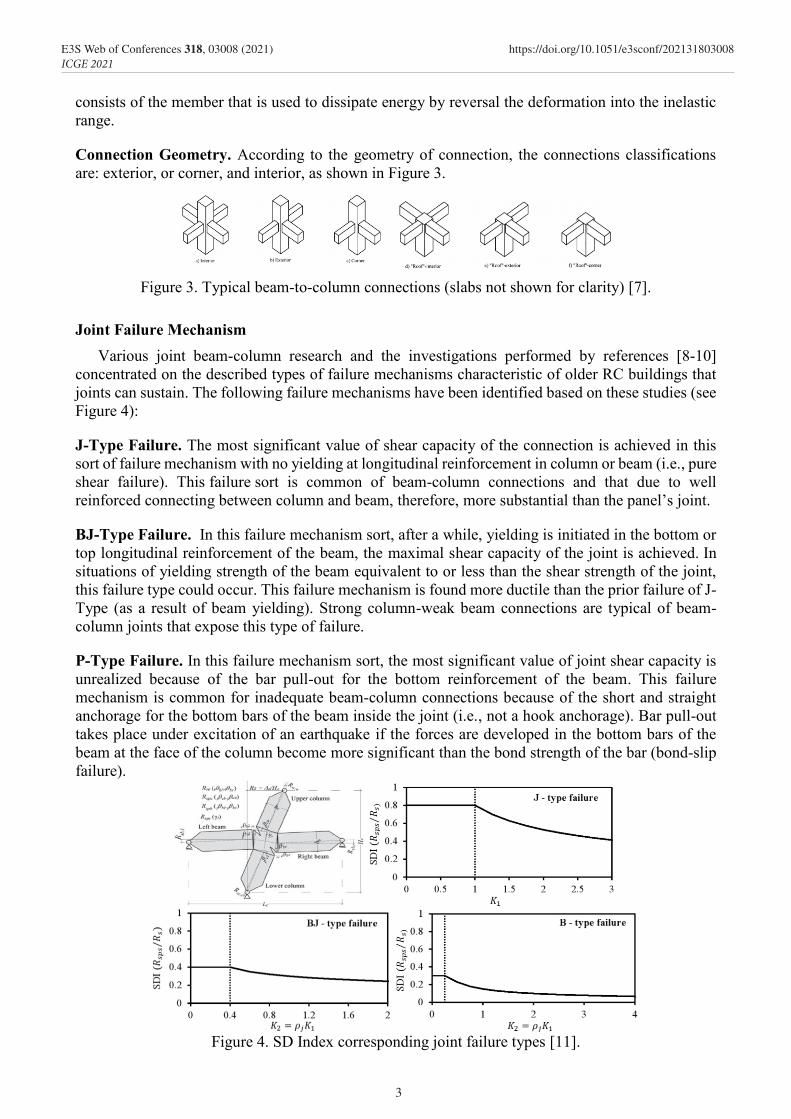
Connection Geometry. According to the geometry of connection, the connections classifications are: exterior, or corner, and interior, as shown in Figure 3.
Figure 3. Typical beam-to-column connections (slabs not shown for clarity) [7].
Joint Failure Mechanism Various joint beam-column research and the investigations performed by references [8-10]
concentrated on the described types of failure mechanisms characteristic of older RC buildings that joints can sustain. The following failure mechanisms have been identified based on these studies (see Figure 4):
J-Type Failure. The most significant value of shear capacity of the connection is achieved in this sort of failure mechanism with no yielding at longitudinal reinforcement in column or beam (i.e., pure shear failure). This failure sort is common of beam-column connections and that due to well reinforced connecting between column and beam, therefore, more substantial than the panel’s joint.
BJ-Type Failure. In this failure mechanism sort, after a while, yielding is initiated in the bottom or top longitudinal reinforcement of the beam, the maximal shear capacity of the joint is achieved. In situations of yielding strength of the beam equivalent to or less than the shear strength of the joint, this failure type could occur. This failure mechanism is found more ductile than the prior failure of J-Type (as a result of beam yielding). Strong column-weak beam connections are typical of beam-column joints that expose this type of failure.
P-Type Failure. In this failure mechanism sort, the most significant value of joint shear capacity is unrealized because of the bar pull-out for the bottom reinforcement of the beam. This failure mechanism is common for inadequate beam-column connections because of the short and straight anchorage for the bottom bars of the beam inside the joint (i.e., not a hook anchorage). Bar pull-out takes place under excitation of an earthquake if the forces are developed in the bottom bars of the beam at the face of the column become more significant than the bond strength of the bar (bond-slip failure).
Figure 4. SD Index corresponding joint failure types [11].
3
E3S Web of Conferences 318, 03008 (2021) https://doi.org/10.1051/e3sconf/202131803008ICGE 2021
Previous Experimental Studies Various experimental investigations have concentrated on identifying in addition to modifying
the behavior of beam-column connections exposed to seismic excitation over the past four decades. Just a few of these tests illustrated the behavior of exterior joints. Also, new models of shear have advanced based on the shear strain and shear stress data presented according to these tests. This section discusses previous research studies involving the testing of RC exterior beam-column connections. These reported testing indicates either connection shear failure (J-Type failure) or shear failure after yielding at the beam reinforcement in the joint region (BJ-Type failure). In general, the failure due to the failure of anchorage (bar pull-out) in joints is not considered.
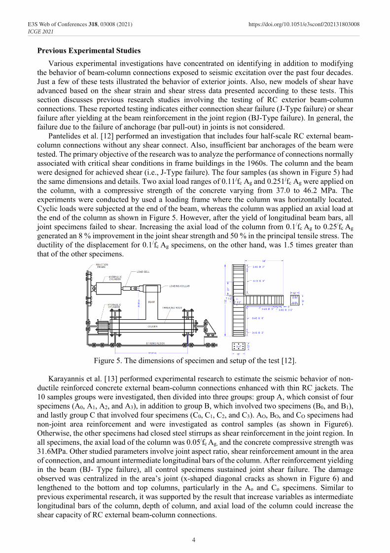
Pantelides et al. [12] performed an investigation that includes four half-scale RC external beam-column connections without any shear connect. Also, insufficient bar anchorages of the beam were tested. The primary objective of the research was to analyze the performance of connections normally associated with critical shear conditions in frame buildings in the 1960s. The column and the beam were designed for achieved shear (i.e., J-Type failure). The four samples (as shown in Figure 5) had the same dimensions and details. Two axial load ranges of 0.11/fc Ag and 0.251/fc Ag were applied on the column, with a compressive strength of the concrete varying from 37.0 to 46.2 MPa. The experiments were conducted by used a loading frame where the column was horizontally located. Cyclic loads were subjected at the end of the beam, whereas the column was applied an axial load at the end of the column as shown in Figure 5. However, after the yield of longitudinal beam bars, all joint specimens failed to shear. Increasing the axial load of the column from 0.1/fc Ag to 0.25/fc Ag generated an 8 % improvement in the joint shear strength and 50 % in the principal tensile stress. The ductility of the displacement for 0.1/fc Ag specimens, on the other hand, was 1.5 times greater than that of the other specimens.
Figure 5. The dimensions of specimen and setup of the test [12].
Karayannis et al. [13] performed experimental research to estimate the seismic behavior of non-
ductile reinforced concrete external beam-column connections enhanced with thin RC jackets. The 10 samples groups were investigated, then divided into three groups: group A, which consist of four specimens (A0, A1, A2, and A3), in addition to group B, which involved two specimens (B0, and B1), and lastly group C that involved four specimens (C0, C1, C2, and C3). AO, BO, and CO specimens had non-joint area reinforcement and were investigated as control samples (as shown in Figure6). Otherwise, the other specimens had closed steel stirrups as shear reinforcement in the joint region. In all specimens, the axial load of the column was 0.05/fc Ag, and the concrete compressive strength was 31.6MPa. Other studied parameters involve joint aspect ratio, shear reinforcement amount in the area of connection, and amount intermediate longitudinal bars of the column. After reinforcement yielding in the beam (BJ- Type failure), all control specimens sustained joint shear failure. The damage observed was centralized in the area’s joint (x-shaped diagonal cracks as shown in Figure 6) and lengthened to the bottom and top columns, particularly in the Ao and Co specimens. Similar to previous experimental research, it was supported by the result that increase variables as intermediate longitudinal bars of the column, depth of column, and axial load of the column could increase the shear capacity of RC external beam-column connections.
4
E3S Web of Conferences 318, 03008 (2021) https://doi.org/10.1051/e3sconf/202131803008ICGE 2021

Previous Experimental Studies Various experimental investigations have concentrated on identifying in addition to modifying
the behavior of beam-column connections exposed to seismic excitation over the past four decades. Just a few of these tests illustrated the behavior of exterior joints. Also, new models of shear have advanced based on the shear strain and shear stress data presented according to these tests. This section discusses previous research studies involving the testing of RC exterior beam-column connections. These reported testing indicates either connection shear failure (J-Type failure) or shear failure after yielding at the beam reinforcement in the joint region (BJ-Type failure). In general, the failure due to the failure of anchorage (bar pull-out) in joints is not considered.
Pantelides et al. [12] performed an investigation that includes four half-scale RC external beam-column connections without any shear connect. Also, insufficient bar anchorages of the beam were tested. The primary objective of the research was to analyze the performance of connections normally associated with critical shear conditions in frame buildings in the 1960s. The column and the beam were designed for achieved shear (i.e., J-Type failure). The four samples (as shown in Figure 5) had the same dimensions and details. Two axial load ranges of 0.11/fc Ag and 0.251/fc Ag were applied on the column, with a compressive strength of the concrete varying from 37.0 to 46.2 MPa. The experiments were conducted by used a loading frame where the column was horizontally located. Cyclic loads were subjected at the end of the beam, whereas the column was applied an axial load at the end of the column as shown in Figure 5. However, after the yield of longitudinal beam bars, all joint specimens failed to shear. Increasing the axial load of the column from 0.1/fc Ag to 0.25/fc Ag generated an 8 % improvement in the joint shear strength and 50 % in the principal tensile stress. The ductility of the displacement for 0.1/fc Ag specimens, on the other hand, was 1.5 times greater than that of the other specimens.
Figure 5. The dimensions of specimen and setup of the test [12].
Karayannis et al. [13] performed experimental research to estimate the seismic behavior of non-
ductile reinforced concrete external beam-column connections enhanced with thin RC jackets. The 10 samples groups were investigated, then divided into three groups: group A, which consist of four specimens (A0, A1, A2, and A3), in addition to group B, which involved two specimens (B0, and B1), and lastly group C that involved four specimens (C0, C1, C2, and C3). AO, BO, and CO specimens had non-joint area reinforcement and were investigated as control samples (as shown in Figure6). Otherwise, the other specimens had closed steel stirrups as shear reinforcement in the joint region. In all specimens, the axial load of the column was 0.05/fc Ag, and the concrete compressive strength was 31.6MPa. Other studied parameters involve joint aspect ratio, shear reinforcement amount in the area of connection, and amount intermediate longitudinal bars of the column. After reinforcement yielding in the beam (BJ- Type failure), all control specimens sustained joint shear failure. The damage observed was centralized in the area’s joint (x-shaped diagonal cracks as shown in Figure 6) and lengthened to the bottom and top columns, particularly in the Ao and Co specimens. Similar to previous experimental research, it was supported by the result that increase variables as intermediate longitudinal bars of the column, depth of column, and axial load of the column could increase the shear capacity of RC external beam-column connections.
AO BO CO Figure 6. Dimensions and reinforcement details of control specimens & Damage and cracking mode
of specimens [13].
Elshafiey et al. [14] carried out an experimental analysis to examine the performance of Type-1 beam-column connections where the beam was exposed to shear stresses caused by a combination of torsional moment and shear force (beam eccentric loading). To understand the complicated behavior due to the efficient loading transferred from the beam to the column, eight samples of beam-column joint were designed and experimented with before failure. The results of the test illustrated the value of both longitudinal side and compression reinforcement beam steel design, where the insufficient embedded length of both longitudinal and reinforcement steel into the joint panel through stirrups limited the ultimate capacity of the beam but preserved the failure zone of failure out of the joint panel. Eventually, they introduced and studied a three-dimensional truss model. The observations of the three-dimensional model demonstrated significant consistency with the results obtained, as shown in Figure 7.
Figure7: show the result of the specimen; a: load-deflection relationship; b: torque-twist angle
relationship [14].
Ahmed et al. [15] produced a radical way of improving the ductility of high strength concrete exterior beam-column connection by differing the top reinforcement detailing of the beam. Two joint types were investigated; specimens of type 1 were designed according to regular standards, while specimens of type 2 were designed by minimizing the top anchorage reinforcement of the beam in the column, as shown in Figure 8. To investigate the reduction of stiffness and energy dissipation by joints, the load-deflection behavior was tested. The results of experimental tests illustrated that specimens of type-2 were significantly more ductile compared with specimens of type-1. Without significant degradation in stiffness, the energy of type-2 joints dissipated (with reducing beam’s reinforcement bars region by 40 percent) was 41.5 percent greater than type-1 joints. It was found that the crack place moved from inside the joint to the face of the beam-column joint by decreasing
5
E3S Web of Conferences 318, 03008 (2021) https://doi.org/10.1051/e3sconf/202131803008ICGE 2021

the steel reinforcement in the beam, which can be due to increasing the ductility in type 2 joints, as shown in Figure 8. This study demonstrates that the fatigue and absorption capacity of the energy could be improved by adjusting the information of steel reinforcement near the exterior beam-column joints, thereby providing improved performance with seismic action.
Figure8: Beam-Column joint test’s results, (a) Crack Pattern in Type-2 Specimens and; (b)
Comparison of Stiffness Degradation of Type-1 and Type-2 Joints (average of three specimens), [15].
Previous Analytical Studies In investigating the stress analysis and deformation of construction and bridge systems, the finite
element method is a successful technique for numerically analyzing a wide variety of engineering problems. Specific problems can now be modeled effectively due to advances in computing science and CAD systems, and many alternative configurations can be evaluated on a computer. ABAQUS, DIANA, and Vector2 are only a handful of the FE modules available to make the task of creating and solving a model simpler. This chapter provided a review of models that may be suitable for exterior beam-column joints.
Favvata et al. [16] provide an effective and efficient model for the simulation of failure and local damage of external RC beam-column joints that can be effectively used in multi-story RC frame structure research. A model was presented for the local inelastic response in the multi-story RC frame structure of external RC beam-column joints simulation. A significant consideration is attached to the definition of the key characteristics of the joint's actual seismic response, including the degradation of stiffness and strength. The suggested model was formulated for nonlinear static and dynamic structural analysis as a rotational spring element into the general program. And a procedure is also provided for evaluating the necessary parameters of the model. The comparison with 12 RC external joints experimental results shows the efficiency of the suggested joint element model. Also, the effect of the local nonlinear response of RC external beam-column joints on the column ductility parameters, total seismic response, and the failure mode of a multi-story RC frame structure is studied by using the suggested element.
(a) (b) (c) (d)
Figure 9: Proposed model for the simulation of the external reinforced concrete beam-column connections: (a) Analytical model partial elevation view of a connection area; (b) envelope curve of
the proposed model; (c) response model during a typical hysteretic cycle; and (d) hysteretic response of the proposed model including pinching effect [16].
(a) (b)
6
E3S Web of Conferences 318, 03008 (2021) https://doi.org/10.1051/e3sconf/202131803008ICGE 2021

the steel reinforcement in the beam, which can be due to increasing the ductility in type 2 joints, as shown in Figure 8. This study demonstrates that the fatigue and absorption capacity of the energy could be improved by adjusting the information of steel reinforcement near the exterior beam-column joints, thereby providing improved performance with seismic action.
Figure8: Beam-Column joint test’s results, (a) Crack Pattern in Type-2 Specimens and; (b)
Comparison of Stiffness Degradation of Type-1 and Type-2 Joints (average of three specimens), [15].
Previous Analytical Studies In investigating the stress analysis and deformation of construction and bridge systems, the finite
element method is a successful technique for numerically analyzing a wide variety of engineering problems. Specific problems can now be modeled effectively due to advances in computing science and CAD systems, and many alternative configurations can be evaluated on a computer. ABAQUS, DIANA, and Vector2 are only a handful of the FE modules available to make the task of creating and solving a model simpler. This chapter provided a review of models that may be suitable for exterior beam-column joints.
Favvata et al. [16] provide an effective and efficient model for the simulation of failure and local damage of external RC beam-column joints that can be effectively used in multi-story RC frame structure research. A model was presented for the local inelastic response in the multi-story RC frame structure of external RC beam-column joints simulation. A significant consideration is attached to the definition of the key characteristics of the joint's actual seismic response, including the degradation of stiffness and strength. The suggested model was formulated for nonlinear static and dynamic structural analysis as a rotational spring element into the general program. And a procedure is also provided for evaluating the necessary parameters of the model. The comparison with 12 RC external joints experimental results shows the efficiency of the suggested joint element model. Also, the effect of the local nonlinear response of RC external beam-column joints on the column ductility parameters, total seismic response, and the failure mode of a multi-story RC frame structure is studied by using the suggested element.
(a) (b) (c) (d)
Figure 9: Proposed model for the simulation of the external reinforced concrete beam-column connections: (a) Analytical model partial elevation view of a connection area; (b) envelope curve of
the proposed model; (c) response model during a typical hysteretic cycle; and (d) hysteretic response of the proposed model including pinching effect [16].
(a) (b)
The conclusions have been illustrated that the local effect of the low external joints capacity on the frame's behavior: (a) the multi-story frame failure mode significantly changes relative to the one characteristic beam-column joints as rigid, as plastic hinges do not evolve in the beams adjoining to the joints; (b )the degradation of the core area of the joints results in a decrease in the columns maximum ductility requirements at the base of the multi-story structure, and (c) the overall inter-story drifts of the 8-story frame structure usually enhance relative to the rigid joint-based simulation.
Saito and Kikuchi [17] developed a new model for large-deformation of the beam-column joint, nonlinear behavior of reinforced concrete frames under cyclic loading. A multi-node joint panel zone and reinforcing bar elements composed the current model. The model includes the bond-slip of the beam-column joint's reinforcing and shear behaviors. And comparisons of the analytical and test results (as shown in Figure10) suggest that in terms of both energy dissipation and pinching effect induced by bond-slip and shear behavior of the joint in the beam-column connection, the proposed beam-column joint model should simulate the fundamental characteristics of nonlinear cyclic RC beam-column joint behavior well. If bond-slip and joint shear deformation are not considered, the absorption of hysteretic energy is greatly overestimated.
Figure 10:Comparisons of top bar slip of reinforcement at the center of the beam-column
connection [17]. Abbas et al. [18] performed Finite Element simulations to examine the behavior of steel-fiber RC
(SFRC) beam-column connections under a combination of constant column axial and reversed cyclic load as tested by Bayasi and Gebman (2002). The concrete element was modeled using the 8-node brick elements. A sensitivity analysis was performed to determine the best mesh element size. The element size was50 mm based on the validation of the experiment, as it provided the best findings in reproducing the experiment information. The reinforcement bars were accurately located to suit the reinforcement information in the experiment using the two-node truss element. Also, during the study, the developed stresses were disturbed by using a rigid element, besides avoiding the pre-mature localized cracking at the supports and the loading point. Tensile post-cracking was increased due to used the steel fibers. Also, they made the concrete more ductile than plain concrete, according to the experiment (Kotsovos and Pavlovi, 1995). Moreover, In terms of uniaxial compression, no change was found. The development of steel fibers strengthened concrete in stress, avoiding crack formation, but their effect on concrete in compression can be ignored. As a result, concrete is simulated by using the brittle cracking model of ABAQUS software. Tensile cracking determines the material behavior of concrete, so this model was used. The standard steel reinforcing bars were modeled using a bilinear curve of elastic-plastic material as shown in Figure 11b. The study was performed, with a low rate of loading, by using the procedure of the explicit dynamic that available in ABAQUS/Explicit. The experiment findings and the FE study were in strong agreement(as shown in Figure11). The FE study failure was related to enhancing the kinetic energy, suggesting that significant cracks had developed across the joint zone. However, the maximum achieved value of the ductility in the FE was 50% smaller than in the experimental.
Kotsovou et al. [19] suggested a method that is dissimilar from any method suggested to date, does unneeded calibration by using experimental behavior of the joint data, and is found to be adequate for predicting the failure mode of exterior beam-column joint sub-assemblages for more than 90% of the 153 cases examined, as well as safe load carrying capacity predictions of joint. In comparison to this proposed method, the current code methods fail to determine joint strength and
7
E3S Web of Conferences 318, 03008 (2021) https://doi.org/10.1051/e3sconf/202131803008ICGE 2021
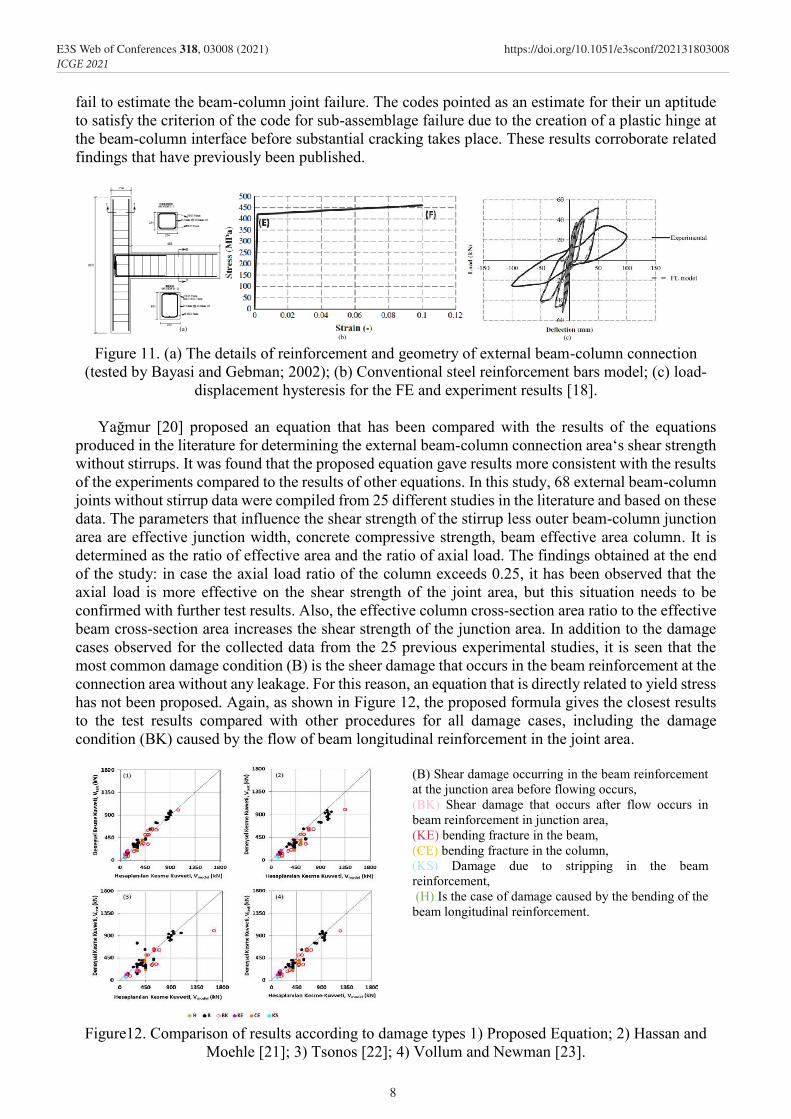
fail to estimate the beam-column joint failure. The codes pointed as an estimate for their un aptitude to satisfy the criterion of the code for sub-assemblage failure due to the creation of a plastic hinge at the beam-column interface before substantial cracking takes place. These results corroborate related findings that have previously been published.
Figure 11. (a) The details of reinforcement and geometry of external beam-column connection
(tested by Bayasi and Gebman; 2002); (b) Conventional steel reinforcement bars model; (c) load-displacement hysteresis for the FE and experiment results [18].
Yağmur [20] proposed an equation that has been compared with the results of the equations
produced in the literature for determining the external beam-column connection area‘s shear strength without stirrups. It was found that the proposed equation gave results more consistent with the results of the experiments compared to the results of other equations. In this study, 68 external beam-column joints without stirrup data were compiled from 25 different studies in the literature and based on these data. The parameters that influence the shear strength of the stirrup less outer beam-column junction area are effective junction width, concrete compressive strength, beam effective area column. It is determined as the ratio of effective area and the ratio of axial load. The findings obtained at the end of the study: in case the axial load ratio of the column exceeds 0.25, it has been observed that the axial load is more effective on the shear strength of the joint area, but this situation needs to be confirmed with further test results. Also, the effective column cross-section area ratio to the effective beam cross-section area increases the shear strength of the junction area. In addition to the damage cases observed for the collected data from the 25 previous experimental studies, it is seen that the most common damage condition (B) is the sheer damage that occurs in the beam reinforcement at the connection area without any leakage. For this reason, an equation that is directly related to yield stress has not been proposed. Again, as shown in Figure 12, the proposed formula gives the closest results to the test results compared with other procedures for all damage cases, including the damage condition (BK) caused by the flow of beam longitudinal reinforcement in the joint area.
(B) Shear damage occurring in the beam reinforcement at the junction area before flowing occurs, (BK) Shear damage that occurs after flow occurs in beam reinforcement in junction area, (KE) bending fracture in the beam, (CE) bending fracture in the column, (KS) Damage due to stripping in the beam reinforcement, (H) Is the case of damage caused by the bending of the beam longitudinal reinforcement.
Figure12. Comparison of results according to damage types 1) Proposed Equation; 2) Hassan and Moehle [21]; 3) Tsonos [22]; 4) Vollum and Newman [23].
(a) (b) (c)
8
E3S Web of Conferences 318, 03008 (2021) https://doi.org/10.1051/e3sconf/202131803008ICGE 2021

fail to estimate the beam-column joint failure. The codes pointed as an estimate for their un aptitude to satisfy the criterion of the code for sub-assemblage failure due to the creation of a plastic hinge at the beam-column interface before substantial cracking takes place. These results corroborate related findings that have previously been published.
Figure 11. (a) The details of reinforcement and geometry of external beam-column connection
(tested by Bayasi and Gebman; 2002); (b) Conventional steel reinforcement bars model; (c) load-displacement hysteresis for the FE and experiment results [18].
Yağmur [20] proposed an equation that has been compared with the results of the equations
produced in the literature for determining the external beam-column connection area‘s shear strength without stirrups. It was found that the proposed equation gave results more consistent with the results of the experiments compared to the results of other equations. In this study, 68 external beam-column joints without stirrup data were compiled from 25 different studies in the literature and based on these data. The parameters that influence the shear strength of the stirrup less outer beam-column junction area are effective junction width, concrete compressive strength, beam effective area column. It is determined as the ratio of effective area and the ratio of axial load. The findings obtained at the end of the study: in case the axial load ratio of the column exceeds 0.25, it has been observed that the axial load is more effective on the shear strength of the joint area, but this situation needs to be confirmed with further test results. Also, the effective column cross-section area ratio to the effective beam cross-section area increases the shear strength of the junction area. In addition to the damage cases observed for the collected data from the 25 previous experimental studies, it is seen that the most common damage condition (B) is the sheer damage that occurs in the beam reinforcement at the connection area without any leakage. For this reason, an equation that is directly related to yield stress has not been proposed. Again, as shown in Figure 12, the proposed formula gives the closest results to the test results compared with other procedures for all damage cases, including the damage condition (BK) caused by the flow of beam longitudinal reinforcement in the joint area.
(B) Shear damage occurring in the beam reinforcement at the junction area before flowing occurs, (BK) Shear damage that occurs after flow occurs in beam reinforcement in junction area, (KE) bending fracture in the beam, (CE) bending fracture in the column, (KS) Damage due to stripping in the beam reinforcement, (H) Is the case of damage caused by the bending of the beam longitudinal reinforcement.
Figure12. Comparison of results according to damage types 1) Proposed Equation; 2) Hassan and Moehle [21]; 3) Tsonos [22]; 4) Vollum and Newman [23].
(a) (b) (c)
Diro and Kabeta [24] performed a nonlinear finite element analysis of RC external beam-column joint exposed to lateral loading to determine the failure mode of shear in terms of deformations, cracking patterns, and shear capacity of the joint by used ABAQUS software. With a limited amount of tensile reinforcement, the improvement in the longitudinal tension reinforcement ratio of the beam did not demonstrate a major shear strength changing. The cracking pattern may change significantly from the beam’s edge to the column’s edge. At the concrete crushing stage, the resistance of shear capacity has increased.
Figure 13. Comparison of numerical and experimental results, the influence of concrete
compressive strength, and effect of mesh sizes on finite element result [24].
Summary This literature has presented some previous researches on external reinforced concrete beam-
column connections under cyclic loading. Tables 1 and 2 show a summary of these works.
Table 1. Summary of previous experimental works. Ref. Used parameters Objectives of work The results
[12]
The dimensions and details are the for beam and columns, no shear
links at joints, beams with insufficient anchorage, two axial
loads applied to the column, and the beam subjected to cyclic loading at
the ends
analyze the performance of
connections normally associated with critical
shear conditions in frame buildings in the
1960s
After the yield of longitudinal beam bars, all joint specimens failed to shear. Increasing the
axial load of the column from 0.1/fc Ag to 0.25/fc Ag generated an 8 % improvement in the joint shear strength and 50% in the principal tensile
stress. The ductility of the displacement for 0.1/fc Ag specimens, on the other hand, was 1.5 times greater than that of the other specimens
[13]
3 samples as a control sample without reinforcement the area of
joint, but the other had closed steel stirrups joint aspect ratio, shear
reinforcement amount in the area of connection, and amount
intermediate longitudinal bars of the column
estimate the seismic behavior of non-ductile
RC external beam-column connections enhanced with thin reinforced concrete
jackets
The damage observed was centralized in the area’s joint (x-shaped diagonal cracks).
Also, increasing the variables as intermediate longitudinal bars of the column, depth of
column, and axial load of the column could increase the capacity of the joint’s shear
[14]
The parameters were the beam load eccentricity, compression
reinforcing steel, the beam side's configuration, the beam rigidity,
and the existence of the joint reinforcing stirrups
performance of Type-1 eccentric beam-column
connections
Insufficient embedded length of both longitudinal and reinforcement steel into the
joint panel through stirrups limited the ultimate capacity of the beam but preserved the failure
zone of failure out of the joint panel
[15]
specimens of type1 were presented as per regular standards as
specimens of type2 were prepared by decreased the top reinforcement
anchoring of the beam in the column. Load-deflection behavior was tested to observe the energy
dissipation and stiffness degradation by connections
Produced a radical way of improving the ductility of high-strength concrete
exterior beam-column connection by differing the top reinforcement detailing of the beam
It was found that the crack place moved from inside the joint to the face of the joint by
decreasing the steel reinforcement in the beam, which can be due to increasing the ductility in
type 2 joint. Also, it demonstrates that behavior of fatigue and absorption capacity of the energy could be improved by adjusting the information of steel reinforcement nearby the exterior beam-
column joints, thereby providing improved performance with seismic action
9
E3S Web of Conferences 318, 03008 (2021) https://doi.org/10.1051/e3sconf/202131803008ICGE 2021

Table 2. Summary of previous analytical studies. Ref. Used parameters Objectives of study The results
[16] actual seismic response, including
the degradation of stiffness and strength
an effective and efficient model for the simulation
of failure and local damage of connections
the degradation of the core area of the joints results in a decrease in the columns maximum ductility requirements at the base of the multi-
story structure
[17]
Reinforcement‘s bond-slip (without joint shear deformation)
and joint shear deformation (without bond-slip of
reinforcements) were studied.
Modeled for large-deformation of the beam-column joint, nonlinear behavior of reinforced concrete frames under
cyclic loading
Comparison of the analytical and test results reveals that the proposed beam-column joint
model can represent well the fundamental characteristics of nonlinear RC beam-column
connection‘s behavior
[18] elements size was50 mm
developed stresses
Study behavior of steel-fiber strengthen under of
axial and cyclic load
Tensile post-cracking was increased uniaxial compression; no change was found. The tensile
cracking determines the material behavior of concrete
[19] two parameters groups are tested,
group1 contains fifteen parameters, and group 2 of twelve
produced a method proper for the joint‘s
structural assessment in the form of an analytical
algorithm obtained by used the artificial neural
networks
The method introduced to date does not need calibration by using the experimental
information on the behavior of the joint, is observed able of foretelling failure mode
[20]
the axial load is more effective on the shear strength of the
connection area, and the ratio of the effective column cross-section area to the effective beam cross-section area increases the shear
strength of the junction area
compared with the results of the equations
produced in the literature for determining the
external beam-column connection area‘s shear strength without stirrups
It has been observed that the axial load is more effective on the shear strength of the connection
area. The ratio of the effective column cross-section area to the effective beam cross-section area increases the shear strength of the junction area. In addition to the damage cases observed
for the collected data from the 25 previous experimental studies
[24] limited amount of tensile reinforcement
performed a nonlinear finite element analysis joint exposed to lateral
loading
The improvement in the longitudinal tension reinforcement ratio of the beam did not
demonstrate a major shear strength changing. The cracking pattern may change significantly from the beam’s edge to the column’s edge. At the concrete crushing stage, the resistance of
shear capacity has increased.
Conclusions The following conclusions can be based on the evaluation of the extensive literature review also,
the existing knowledge of the seismic of external RC beam-column joints behavior provided in this literature:
Structural RC beam-column joints designed before 1980, particularly the developing countries, are seismically insufficient in design and consequently highly vulnerable to sustaining shear joint’s failure under seismic excitation. According to experimental observations of beam-column connection also post-earthquake reconnaissance studies, this is highly established.
To effectively exceed and minimize the potential risks these older constructions affect society, consequently the safety of the public and the risk of economic, there is an increased necessity to expected, properly assess, and strengthen the older existing buildings.
Because of developed tensile cracks parallel to the compressive loading axis, the compressive strength of the concrete inside the panel of connection is decreased. Because of the constant opening and closing of holes, load reversal produces an additional reduction of the concrete strength.
10
E3S Web of Conferences 318, 03008 (2021) https://doi.org/10.1051/e3sconf/202131803008ICGE 2021

Table 2. Summary of previous analytical studies. Ref. Used parameters Objectives of study The results
[16] actual seismic response, including
the degradation of stiffness and strength
an effective and efficient model for the simulation
of failure and local damage of connections
the degradation of the core area of the joints results in a decrease in the columns maximum ductility requirements at the base of the multi-
story structure
[17]
Reinforcement‘s bond-slip (without joint shear deformation)
and joint shear deformation (without bond-slip of
reinforcements) were studied.
Modeled for large-deformation of the beam-column joint, nonlinear behavior of reinforced concrete frames under
cyclic loading
Comparison of the analytical and test results reveals that the proposed beam-column joint
model can represent well the fundamental characteristics of nonlinear RC beam-column
connection‘s behavior
[18] elements size was50 mm
developed stresses
Study behavior of steel-fiber strengthen under of
axial and cyclic load
Tensile post-cracking was increased uniaxial compression; no change was found. The tensile
cracking determines the material behavior of concrete
[19] two parameters groups are tested,
group1 contains fifteen parameters, and group 2 of twelve
produced a method proper for the joint‘s
structural assessment in the form of an analytical
algorithm obtained by used the artificial neural
networks
The method introduced to date does not need calibration by using the experimental
information on the behavior of the joint, is observed able of foretelling failure mode
[20]
the axial load is more effective on the shear strength of the
connection area, and the ratio of the effective column cross-section area to the effective beam cross-section area increases the shear
strength of the junction area
compared with the results of the equations
produced in the literature for determining the
external beam-column connection area‘s shear strength without stirrups
It has been observed that the axial load is more effective on the shear strength of the connection
area. The ratio of the effective column cross-section area to the effective beam cross-section area increases the shear strength of the junction area. In addition to the damage cases observed
for the collected data from the 25 previous experimental studies
[24] limited amount of tensile reinforcement
performed a nonlinear finite element analysis joint exposed to lateral
loading
The improvement in the longitudinal tension reinforcement ratio of the beam did not
demonstrate a major shear strength changing. The cracking pattern may change significantly from the beam’s edge to the column’s edge. At the concrete crushing stage, the resistance of
shear capacity has increased.
Conclusions The following conclusions can be based on the evaluation of the extensive literature review also,
the existing knowledge of the seismic of external RC beam-column joints behavior provided in this literature:
Structural RC beam-column joints designed before 1980, particularly the developing countries, are seismically insufficient in design and consequently highly vulnerable to sustaining shear joint’s failure under seismic excitation. According to experimental observations of beam-column connection also post-earthquake reconnaissance studies, this is highly established.
To effectively exceed and minimize the potential risks these older constructions affect society, consequently the safety of the public and the risk of economic, there is an increased necessity to expected, properly assess, and strengthen the older existing buildings.
Because of developed tensile cracks parallel to the compressive loading axis, the compressive strength of the concrete inside the panel of connection is decreased. Because of the constant opening and closing of holes, load reversal produces an additional reduction of the concrete strength.
Many failure mechanism types are recognized that could be caused by defective connections characteristic of older RC constructions. These types involve shear failure shortly after yielding in the reinforcement (BJ-Type), connection shear failure without yielding reinforcement (J-Type), in addition to failure because of the pull-out bar failure (P-Type). Other forms of failure are recognized but are less familiar.
References [1] FEMA 313, 1998. NEHRP: Promoting the Adoption and Enforcement of Seismic Building Codes:
A Guidebook for State Earthquake and Mitigation Managers. Washington, D.C., Federal Emergency Management Agency,.
[2] Uniform Building Code (UBC), 1976. International Conference of Building Officials (ICBO), Whittier, California.
[3] Soyluk, A. and Harmankaya, Z.Y., 2012. The history of development in Turkish seismic design codes. International Journal of Civil & Environmental Engineering, 12(1), pp.25-29.
[4] Mosier, W. G., 2000. Seismic assessment of reinforced concrete beam-column joints. M.Sc. Thesis, University of Washington, Seattle.
[5] Mitra, N., 2007. An analytical study of reinforced concrete beam-column joint behavior under seismic loading. Ph.D Disertation, University of Washington, USA.
[6] Shiohara, H., 2001. New model for shear failure of RC interior beam-column connections. Journal of Structural Engineering, 127(2), pp.152-160.
[7] ACI 352R-2, 2002. Recommendations for design of beam column connections in monolithic reinforced concrete structures. ACI code committee, USA.
[8] Lowes, L.N. and Altoontash, A., 2003. Modeling reinforced-concrete beam-column joints subjected to cyclic loading. Journal of Structural Engineering, 129(12), pp.1686-1697.
[9] Kim, J. and LaFave, J.M., 2007. Key influence parameters for the joint shear behaviour of reinforced concrete (RC) beam–column connections. Engineering structures, 29(10), pp.2523-2539.
[10] Hassan, W.M., 2011. Analytical and experimental assessment of seismic vulnerability of beam-column joints without transverse reinforcement in concrete buildings. PhD Thesis, University of California, Berkeley.
[11] Gombosuren, D. and Maki, T., 2020. Prediction of Joint Shear Deformation Index of RC Beam–Column Joints. Buildings, 10(10), p.176..
[12] Pantelides, C.P., Clyde, C. and Reaveley, L.D., 2002. Performance-based evaluation of reinforced concrete building exterior joints for seismic excitation. Earthquake Spectra, 18(3), pp.449-480.
[13] Karayannis, C.G., Chalioris, C.E. and Sirkelis, G.M., 2008. Local retrofit of exterior RC beam–column joints using thin RC jackets—An experimental study. Earthquake Engineering & Structural Dynamics, 37(5), pp.727-746.
[14] Elshafiey, T.M., Atta, A.M., Afefy, H.M. and Ellithy, M.E., 2016. Structural performance of reinforced concrete exterior beam–column joint subjected to combined shear and torsion. Advances in Structural Engineering, 19(2), pp.327-340.
[15] Ahmed, A., Saleem, M.M. and Siddiqui, Z.A., 2019. Effect of Varying Top Beam Reinforcement Anchorage Details on Ductility of HSC Beam-Column Joints. KSCE Journal of Civil Engineering, 23(5), pp.2272-2280.
[16] Favvata, M.J., Izzuddin, B.A. and Karayannis, C.G., 2008. Modelling exterior beam–column joints for seismic analysis of RC frame structures. Earthquake engineering & structural dynamics, 37(13), pp.1527-1548.
[17] Saito, T. and Kikuchi, M., 2012. A new analytical model for reinforced concrete beam-column joints subjected to cyclic loading. In Proceedings Of The Fifthteenth World Conference On Earthquake Engineering Lisbon, Portugal (Vol. 2012).
11
E3S Web of Conferences 318, 03008 (2021) https://doi.org/10.1051/e3sconf/202131803008ICGE 2021

[18] Abbas, A.A., Mohsin, S.M.S. and Cotsovos, D.M., 2014. Seismic response of steel fibre reinforced concrete beam–column joints. Engineering Structures, 59, pp.261-283.
[19] Kotsovou, G.M., Cotsovos, D.M. and Lagaros, N.D., 2017. Assessment of RC exterior beam-column Joints based on artificial neural networks and other methods. Engineering Structures, 144, pp.1-18.
[20] Yağmur, E., 2020. Shear strength prediction for exterior beam-column joint. BEU Journal of Science, 9(2), pp.766-779.
[21] Tsonos, A.D.G., 2010. Performance enhancement of R/C building columns and beam–column joints through shotcrete jacketing. Engineering Structures, 32(3), pp.726-740.
[22] Hassan, W.M. and Moehle, J.P., 2018. Shear Strength of Exterior and Corner Beam-Column Joints without Transverse Reinforcement. ACI Structural Journal, 115(6).
[23] Vollum, R.L. and Newman, J.B., 1999. Strut and tie models for analysis/design of external beam—column joints. Magazine of concrete research, 51(6), pp.415-425.
[24] Diro, G.A. and Kabeta, W.F., 2020. Finite Element Analysis of Key Influence Parameters in Reinforced Concrete Exterior Beam Column Connection Subjected to Lateral Loading. European Journal of Engineering and Technology Research, 5(6), pp.689-697.
12
E3S Web of Conferences 318, 03008 (2021) https://doi.org/10.1051/e3sconf/202131803008ICGE 2021