A report on Diesel Power Plant
24
-
Upload
sangeeth-soman -
Category
Engineering
-
view
264 -
download
5
Transcript of A report on Diesel Power Plant
ABSTRACT
This report explains about the power plant which is use the diesel engine as the
prime mover. This power plant need to output electric energy. Generally it is used for
heavy duty vehicles. It can also be used for power generation, pumping of water etc. A
generating station in which diesel engine is used as the prime mover for the generation of
electrical energy is known as Diesel Power Plant. Diesel power plant is a non-renewable
energy resource. Diesel power plants produce power in the range of 2 to 50MW.The
diesel burns inside the engine and the products of this combustion act as the working
fluid to produce mechanical energy. The diesel engine drives alternator which converts
mechanical energy into electrical energy. As the generation cost is considerable due to
high price of diesel, therefore, such power stations are only used to produce small power.
Although steam power stations and hydro-electric plants are invariably used to generate
bulk power at cheaper costs. Yet diesel power stations are finding favour at places where
demand of power is less, sufficient quantity of coal and water is not available and the
transportation facilities are inadequate. This plants are also standby sets for continuity of
supply to important points such as hospitals, radio stations, cinema houses and telephone
exchanges.

INTRODUCTION
Diesel engine power plant is suitable for small and medium outputs. It is used as central power
station for smaller power supplies and as a standby plant to hydro-electric power plants and
steam power plants.
The diesel power plants are commonly used where fuel prices or reliability of supply favors oil
over coal, where water supply is limited, where loads are relatively small, and where electric line
service is unavailable or is available at too high rates. Diesel power plants in common use have
capacities up to about 5 MW.
The below figure shows various parts of an I.C. engine. The cylinder is the main body of the
engine where in direct combustion of fuel takes place. The cylinder is stationary and the piston
reciprocates inside it. The connecting rod transmits the force given by the piston to the crank,
causing it to turn and thus convert the reciprocating motion of the piston into rotary motion of
the crankshaft.
The valves may be provided
(i) at the top or
(ii) On the side of the engine cylinder.
The cam lifts the push rod through cam follower and the push rod actuates the rocker arm lever
at one end. The other end of Urn rocker arm then gets depressed and that opens the valve. The
valve returns to its seating by the spring after the cam has rotated. The valve stem moves in a
valve guide acts as a bearing.
On a four stroke engine, the inlet and exhaust valves operate, once per cycle, i.e., in two
revolutions of the crankshaft. Consequently, the cam shaft is driven by the crankshaft at exactly
half its rotational speed.

CLASSIFICATION OF INTERNAL COMBUSTION
(I.C.) ENGINES
According to cycle of operation I.C. engines are two types:
(i) Two-stroke cycle engine.
(ii) Four-stroke cycle engine.
The relative advantages and disadvantages of these engines are as follows:
The working or power stroke is completed in two revolutions of the crank shaft in four stroke
cycle engine whereas in two-stroke cycle engine the working stroke is completed in one
revolution. Thus the power obtained from a two- stroke engine should be twice that of power
obtained from four-stroke engine but due to charge loss and power needed to drive scavenge
compressor the actual power obtained from a two-stroke engine is 50 to 60% more than four-
stroke engine. As one working stroke
(i) Is completed for every revolution of crankshaft the turning moment on crankshaft is
more uniform in case of two stroke engine and, therefore, a lighter flywheel serves the
purpose.
(ii) Two-stroke engine is lighter in weight and requires less space than a four-stroke engine
of the same power. This makes it suitable for marine engines,
(iii)In two-stroke engine the power needed to overcome-frictional resistance during suction
and exhaust stroke is saved.
(iv) In a two-stroke engine there is more noise and wear.
(v) The consumption of lubricating oil is greater in a two timid) engine due to large amount
of heat generated.
(vi) Two-stroke engine is simple and its maintenance cost is low
(vii) Scavenging is better in four-stroke engine.
(viii) In two-stroke engine the exhaust port remains open for a very short time which
results in incomplete scavenging and thus dilution of fresh change.
(ix) Construction of combustion chamber is better and simple in two-stroke engine.

Four-stroke Diesel Engine
If four-stroke diesel engine the four operations are completed in two revolutions of crank
shaft. The various operations are as follows:
(i) Suction Stroke. In this stroke in let valve (I.V.) remains open [Fig A] and exhaust valve
(E.V.) remains closed. The descending piston draws in a fresh charge of air to fill the cylinder
with it. The air taken in during suction stroke is nearly at atmospheric pressure. Line ab in the
indicator diagram [Fig. B] represents this stroke.
(ii) Compression Stroke. In this stroke I.V. and E.V. remain closed. Piston moves up and the air
sucked in during suction stroke is compressed to high pressure and temperature (nearly 3.5
kg/cm2 and 600°C). This stroke is represented by the line be in indicator diagram.

Expansion Stroke: During the stroke [Fig. C], I.V. and K.V. remain closed. Injection of
fuel through the fuel valve starts Just before the beginning of this stroke. Due to compression
the temperature of air inside the cylinder becomes high enough to ignite l ltr fuel as soon as it is
injected. The fuel is admitted into the cylinder gradually in such a way that fuel bums at
constant pressure. cd represents the fuel burning operation. The ignited mixture nl nir and fuel
expands and forces the piston downward. Expansion stroke is represented by de

Exhaust Stroke: This stroke is represented by ea. In this stroke E.V. remains open, [Fig. D]
and the rising piston forces the burnt gases out of cylinder.
The exhaust of gases takes place at a pressure little above the atmospheric pressure because of
restricted area of exhaust passages which do not allow the gases to move out of cylinder
quickly. The figure shows the valve timing diagram for a four-stroke diesel engine. The
approximate crank positions are shown when I.V., E.V., and fuel valves open and close. I.D.C.
represents (inner dead centre) and
0. D.C. (outer dead centre), I.V.O. represents (Inlet valve opens) and
1. V.C. represents (Inlet valve closes). Similarly E.V.O. means exhaust valve open and
E.V.C. means exhaust valve closes F.V.O. represents fuel valve opens and F.V.C. represents
fuel closes and F.V.O. represents fuel valve opens.

Two-stroke Diesel Engine
The various operations of a two-stroke diesel engine are shown in Figure. During the
downward movement of piston (down stroke) The exhaust port is uncovered and the removal of
burnt gases takes place. Further movement of the piston uncovers tin transfer port. At this stage
the crank case and cylinder space are in direct communication. The slightly compressed air in
the crank case is transferred to the cylinder (at a pressure of about 0.05 kg/cm2 gauge) through
the transfer port. While the transfer of change from the crank case to the cylinder is taking
place the removal of products of combustion is also taking place simultaneously example the
incoming charge in helping in the rejection of burnt gases, this is known as scavenging. As the
piston moves upward (up stroke) the compression of air starts. Near the end of comparison
stroke the fuel is injected and ignition of fuel is injected place due to heat of compressed air.
Then due to expansion of products of combustion the piston moves downward. As inlet port is
uncovered a fresh change of air gets entered in crank case. Represents constant pressure
combustion line, de represents expansion and exhaust and scavenging are indicated by eab.
The above figure shows valve timing diagram for two-stroke diesel engine. TDC and BDC
represent top dead centre and bottom dead centre respectively. IPO means inlet port opens
and IPC means inlet port closes, EPO represent exhaust port opens and EPS represent’s j
exhaust port closes. FAS mean fuel admission starts and FAI means fuel admission ends.

LAYOUT OF DIESEL POWER PLANT
ESSENTIAL ELEMENTS OF DIESEL POWER PLANT
Components of Diesel Engine Power plant consists of the following systems:
Fuel supply system: It consists of fuel tank for the storage of fuel, fuel filters and pumps to
transfer and inject the fuel. The fuel ml may be supplied at the plant site by trucks, rail, road,
tank, cars etc.
Air intake and exhaust system: It consists of pipes for the y of air and exhaust of the
gases. Filters are provided to remove dust etc. from the incoming air. In the exhaust system
silencer is provided to reduce the noise.
Filters may be of dry type (made up of cloth, felt, glass, wool etc.) It oil bath type. In oil bath
type of filters the air is swept over or through a bath of oil in order that the particles of dust get
coated, of the air intake systems are as follows:
(i) To clean the air intake supply.
(ii) To silence the intake air.
(iii)To supply air for super charging.
The Intake system must cause a minimum pressure loss to avoid reducing engine capacity and
raising the specific fuel consumption. Filters must be cleaned periodically to prevent pressure
loss from clogging. Silencers must be used on some systems to reduce high velocity air noises.
Cooling system: This system provides a proper amount of water circulation all around
the engines to keep the temperature at reasonable level. Pumps are used to discharge the
water inside and the hot water leaving the jacket is cooled in cooling ponds or other devices
and is recalculated again.
Lubricating system: Lubrication is essential to reduce friction and wear of the rubbing
parts. It includes lubricating oil tank, pumps, filters and lubricating oil cooler.
Starting system: For the initial starting of engine the various devices used is
compressed air, battery, electric motor or self starter. Fig. 4.9 (a) shows the auxiliary
equipment of diesel engine power plant.
INTERNAL COMBUSTION ENGINE COOLING METHODS
There are two methods of cooling the I.C. Engines.
a) Air cooling
b) Water cooling.
Air Cooling: It is a direct method of cooling. In air cooled engine fins are cast on the
cylinder head and cylinder barrel to increase its exposed surface of contact with air. Air passes
over fins and carried away heat, with it. Air for cooling the fins may be lined from a blower or
fan driven by the engine. Air moment relative to engine may be used to cool the engine as in
case of motor cycle’s engine. About 13 to 15% of heat is lost by this method. It own air
cooling system. Simplicity and lightness are the ad shows not as effective as water cooling.
The rate of cooling depends upon the velocity, quantity and temperature of cooling air and
size of surface being cooled.
The position of valves, Fins and head in air cooling system. This system is used in motor
cycles, scooters and aero plans.
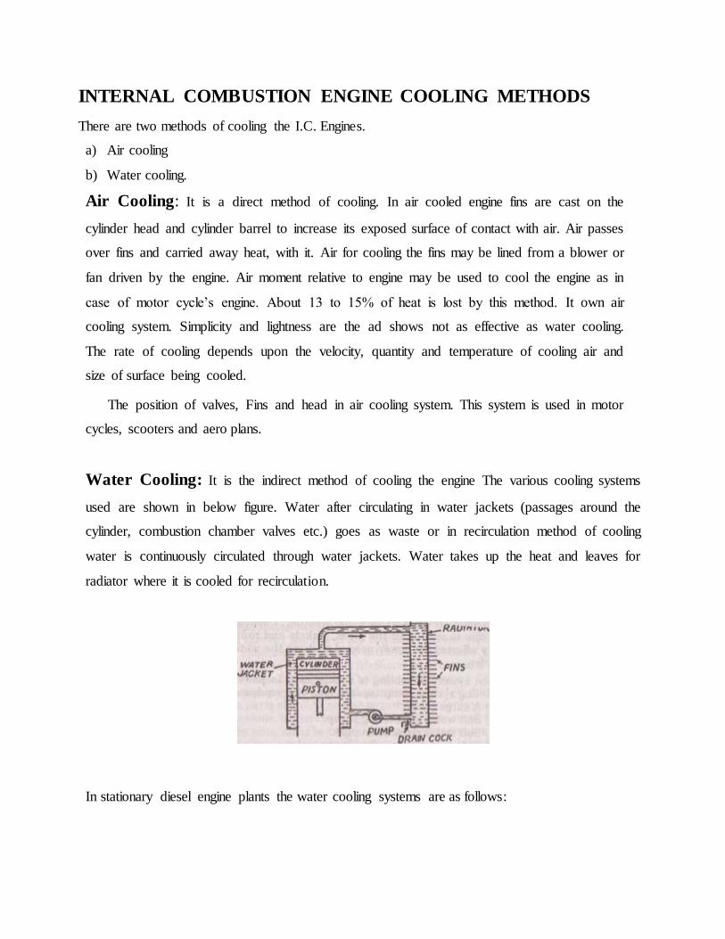
Water Cooling: It is the indirect method of cooling the engine The various cooling systems
used are shown in below figure. Water after circulating in water jackets (passages around the
cylinder, combustion chamber valves etc.) goes as waste or in recirculation method of cooling
water is continuously circulated through water jackets. Water takes up the heat and leaves for
radiator where it is cooled for recirculation.
In stationary diesel engine plants the water cooling systems are as follows:

(i) Open or Single Circuit System: In this system pump draws the water from cooling
pond and forces it into the main engine jackets. Water after circulating through the
engine return to the cooling pond.
(ii) Closed or Double Circuit System: In this system raw water is made to flow
through the heat exchanger when it takes up the heat of jacket water and returns back to the
cooling pond.
heat lost by water cooling is about 25 to 35%. The amount of heat lost is called jacket loss. The
rate of flow of water should be so adjusted that the outlet temperature of cooling water does not
exceed 60’c and rise in temperature of cooling water is limited to 11’c the water used for
cooling purposes should be free from impurities. Water cooling methods permit uniform
cooling. Water cooling creates troubles in very cold weather. Cooling efficiency is reduced due
to scaling in the pipes, jackets and radiator. Engine efficiency affected by power needed to drive
the water pump and radiator fan.
Closed system of cooling is mostly used in power stations. A closed cooling system
comprises the following equipment.
(i) A surge tank.
(ii) Soft water circulating pump.
(iii)Soft water circulation pipe.

(iv) Soft water heat exchanger or cooler.
(v) Raw water softening plant.
(vi) Raw water circulation pump.
(vii) Raw water circulation pipe.
(viii) Raw water cooling arrangement such as cooling tower.
(ix) Thermometer for measuring inlet and outlet temperatures.
(x) Temperature regulator to control the Excessive jacket temperature.
(xi) Safety device to control the excessive jacket temperature.
This system shown is in use soft water for jack cooling. The hot jacket water from the
engine is passed through cooler (heat exchanger) where it is cooled with the help of raw water.
The raw water in turn is cooled by cooling towers.
LUBRICATION
Frictional forces causes wear and tear of rubbing parts of the engine and thereby the life of
the engine is reduced. This requires that some substance should be introduced between the
rubbing surfaces in order to decrease the frictional force between them. Such substance is called
lubricant. The lubricant forms a thin film between the rubbing surfaces and prevents metal to
metal contact. The various parts of an I.C. engine requiring lubrication are cylinder walls and
pistons, big end bearing and crank pins small end bearing and gudgeon pins, main bearing cams
and bearing valve tappet and guides and timing gears etc. The functions of a lubricant are as
follows:
1. It reduces wear and tear of various moving parts by minimizing the force of friction and
ensures smooth running of parts.
2. It helps the piston ring to seal the gases in the cylinder.
3. It removes the heat generated due to friction and keeps the parts cool.
The various lubricants used in engines are of three types:
(i) Liquid Lubricants.
(ii) Solid Lubricants.
(iii) Semi-solid Lubricants.

Liquid oils lubricants are most commonly used. Liquid lubricants are of two types: (a) Mineral
Oils (b) Fatty oils. Graphite, while lead and mica are the solid lubricants. Semi solid lubricants
or greases as they are often called are made from mineral oils and fatty oils.
A Rood lubricant should possess the following properties:
It should not change its state with change in temperature.
It should maintain continuous films between the rubbing surfaces.
It should have high specific heat so that it can remove maximum amount of heat.
It should be free from corrosive acids.
The lubricant should be purified before it enters the engine. It should be free from dust,
moisture, metallic chips, etc. The lubricating oil consumed is nearly 1% of fuel consumption.
The lubricating oil gets heated because of friction of moving parts and should be cooled before
recirculation. The cooling water used in the engine may be used for cooling the lubricant. Nearly
2.5% of heat of fuel is dissipated as heat which is removed by the Lubrication oil.
Lubricating oil is purified by following four methods :
(i) Settling,
(ii) Centrifuging,
(iii)Filtering,
(iv) Chemical reclaiming. The centrifuging widely used gives excellent purification when
properly done.
The figure shows the lubricating oil external circuit.

ENGINE STARTING METHODS
Spark ignition engines (Petrol engines) are used mainly in smaller size where
compression ratio to be our come in cranking is only 5 to 7. Hand and electric motor (6 - 12
V, d - C) cranking are practical. Diesel engines are difficult to be started by hand cranking
because of high compression required and therefore mechanical cranking system is used.
The various methods used for the starting of diesel engine are as follows:
Compressed Air System: Compressed air system is used to start large diesel engines. In
this system compressed air at a pressure of about 20 kg per sq. cm is supplied from an air
bottle I" the engine an inlet valve through the distributor or through inlet manifold. In a
multi-cylinder engine compressed air er.ers mm cylinder and forces down the piston to turn
the engine shall meanwhile the suction stroke of some other cylinder takes place .mi the
compressed air again pushes the piston of this cylinder .mil causes the engine crank shaft
assembly to rotate. Gradually the engine gains momentum and by supplying fuel the engine
will Mart running.
Electric Starting: Electric starting arrangement consists of an electric motor which a drives
pinion which engages a toothed 11 on engine flywheel. Electric power supply for the motor is
made available by a small electric generator driven from the engine in case of small plants a
storage battery of 12 to 36 volts is used to supply power to the electric motor.
The electric motor disengages ' automatically after the engine has started. The advantages of
electric starting are its simplicity and effectiveness.
Starting by an Auxiliary Engine: In this method a small petrol engine is connected to the
main engine through clutch and gear arrangements. Firstly, the clutch is disengaged and petrol
engine is started by hand. Then clutch is gradually engaged and the main engine is cranked for
starting. Automatic disengagement of clutch takes place after the main engine has started.
STARTING PROCEDURE
Actual process of starting the engine differs from engine to engine. Some common steps
for starting the engine are as follows:
1. Before starting the engine it is desirable to check fuel system, lubricating system and cooling
water supply.

2. Depending upon the method of starting a check for the same is essential. If air starting is used
the pressure of air should be checked and also the air system should be checked for possible
leakage. The storage battery should be checked if electric motor is used for starting.
3. There should be no load on the engine.
4. Crank the engine and run it at slow speed for a few minutes and again check the working of
various systems such as fuel, lubricating oil system etc.
The speed of the engine should be gradually increased till it synchronizes with the bus bars.
Then connect the generator to the bus and finally increase the engine speed so that it takes up
desired load.
STOPPING THE ENGINE
The engine should not be stopped abruptly. Top stop the engine the speed should be
decreased gradually until no power is delivered by the alternator. Then the engine is
disconnected from the bus bars and is allowed to run idle for some time.
STARTING AIDS
Starting aids may be used during cold weather to obtain quicker starting of the engine. Ethyl
ether is mostly used as such aid. Glow plugs another starting aid. Glow plug forms a local hot
spot thus imitating the combustion of fuel even if the compression temperature of air in
sufficient.
FUEL SUPPLY
The fuels used in I.C. engines are in liquid form. They HIP preferred because of their high
calorific value and case of storage and handling. The storage of oil fuel is simpler than the solid
I n. I the amount of fuel to be stored depends upon the service hour’s unit vary for different
installations. Bulk storage and engine day I hold the engine fuel. The fuel delivered to the power
plant is received in storage tanks. Pumps draw the oil from storage tanks and supply it is the
smaller day tanks from where the oil is supplied to the engine as shown in figure.

The fuel oil used should be free from impurities. Efforts should he made to prevent
contamination of the fuel. An important step is to reduce the number of times the fuel is handled.
Greater amount OF impurities settle down in the storage tank and remaining impurities are
removed by passing the oil through filters. Storage tank may be located above the ground or
underground. But underground storage tanks are preferred. Fig. 4.17 shows an underground
storage tank. It is provided with coils, heated by steam or hot water to reduce for viscosity and to
lower the pumping cost. Main hole is provided FIN internal access and repair. Vent pipe is
provided to allow the tank to breathe as it is filled or emptied. Level indicator measures the
quantity of oil in the tank, and an overflow line is provided to control the quantity of oil.
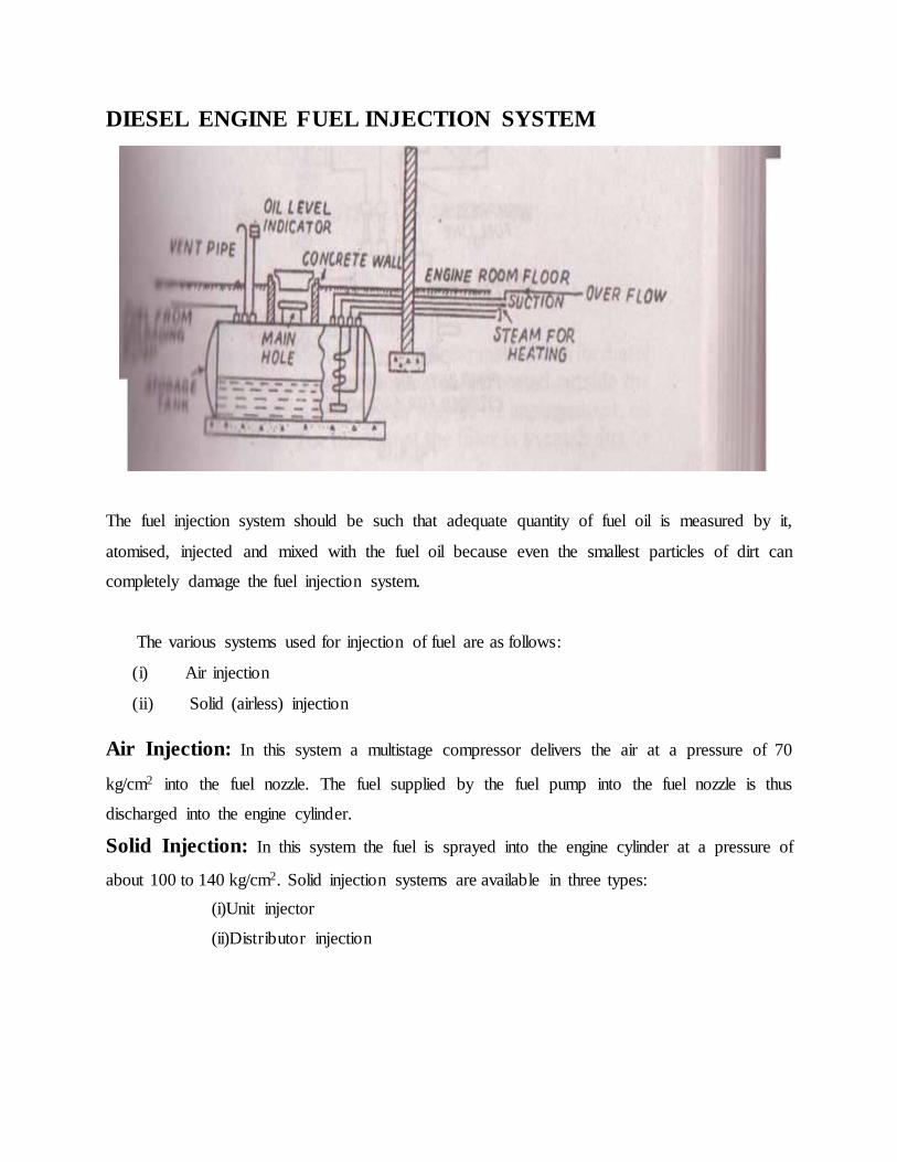
DIESEL ENGINE FUEL INJECTION SYSTEM
The fuel injection system should be such that adequate quantity of fuel oil is measured by it,
atomised, injected and mixed with the fuel oil because even the smallest particles of dirt can
completely damage the fuel injection system.
The various systems used for injection of fuel are as follows:
(i) Air injection
(ii) Solid (airless) injection
Air Injection: In this system a multistage compressor delivers the air at a pressure of 70
kg/cm2 into the fuel nozzle. The fuel supplied by the fuel pump into the fuel nozzle is thus
discharged into the engine cylinder.
Solid Injection: In this system the fuel is sprayed into the engine cylinder at a pressure of
about 100 to 140 kg/cm2. Solid injection systems are available in three types:
(i)Unit injector
(ii)Distributor injection

Unit Injector: In this system a pump plunger is actuated by a cam through a push rod and
rocker arm mechanism. The plunger moving in a barrel raises the pressure of fuel oil meters the
quantity of fuel and controls the injection timing. There is a oring loaded delivery value in the
nozzle. This valve is actuated by the change in fuel oil pressure
Pump Injection: In this system individual pump is provided for each nozzle. The pump
measures the fuel charge and controls the injection timing
Distributor Injection. In this system (Fig. 4.20) a pump measures and pressurizes the fuel
and supplies to it the various nozzles through a distributor block.

Fuel injection takes place through very fine holes in the nozzle body. There are several types of
fuel injection nozzles. Two common types are fuels injection nozzle and pintle nozzle In
multihole nozzle each spray orifice produce a dense and compact spray. In pintle nozzle, fuel
A typical filter and silencer installation for diesel the air system begins with an intake located
outside the building provided with a filter which may be oil impingement, oil path thy type filter.
The function of the filter is to catch dirt by causing it to cling to the surface of filter material. A
silencer is provided between the engine and intake.
ADVANTAGES OF DIESEL POWER PLANT
The various advantages of the diesel engine power plants are follow:
Plant layout is simple.
(i)It is easy to designing and install
(ii)In this plant handling of fuel is easier. Small storage space for fuel is required, there is no
refuse to be disposed oft and oil needed can be easily transported.
(iii)It can be located near load centre.
(iv)A diesel engine extracts more useful work from each heat unit than other types or I.C.
engines. Therefore, it Incomes an attractive prime mover wherever first cost in written off and
operating cost is important.
(v)The plant can be quickly started and can pick up load in very short time.
(vi)There are no standby losses.
(vii)It does not require large amount of water for cooling
(viii)The plant is smaller in size than steam power plant for the same capacity.
(ix)The operation of the plant is easy and less labour is needed to operate the plant.
(x)Compared to steam power plant using steam turbine, the life of diesel power plant is longer.
(xi)Diesel engines operate at higher thermal efficiency MI compared to steam power plants.
DISADVANTAGES OF DIESEL POWER PLANT
1. The plant does not work satisfactorily under overload conditions for longer times.
2. Lubrication cost is high.
3. The capacity of plant is limited & the capacity of plant is limited.

SITE SELECTION
While selection the site for diesel engine power plant the fallowing factors should be
considered:
1. Distance from load centre: The plant should be located near the load centre. This
will minimize the cost of transmission lines, the maintenance and power losses through them.
2. Availability of water: Water should be available in sufficient quantity at the site
selected.
3. Foundation condition: Sub-soil conditions should be such that Inundation at a
reasonable depth should be capable of providing a strong support to the engine.
4. Fuel transportation: The site selected should be near to the source of fuel supply so
that transportation charges are low.
5. Access to site: The site selected should have road and rail transportation facilities.
The site selected should be away from the town so that the smoke and other gases coming out
of the chimneys do not effect the Inhabitants.
APPLICATIONS OF DIESEL POWER PLANT
1. They are quite suitable for mobile power generation and are widely used in transportation
systems consisting of rail roads, ships, automobiles and aero planes.
2. They can be used for electrical power generation in capacities from 100 to 5000 H.P.
3. They can be used as standby power plants.
4. They can be used as peak load plants for some other types of power plants.
5. Industrial concerns where power requirement are small say of the order of 500 kW, diesel power
plants become more economical due to their higher overall efficiency.
Diesel power plant is quite suitable at places where
(i) Fuel prices or reliability of fuel supply favour oil over coal,
(ii) Water supply is limited.
(iii)Loads are relatively small.
(iv) Power from other power plants such as steam, hydro power plants etc. is not available or is
available at too high rates.

COST OF DIESEL POWER PLANT
Cost of any power plant changes rapidly when there are inflationary tends in the
nation’s currency and cost becomes out-of-date far more rapidly than technical
information. A diesel engine power plant may cost about Rs. 1500 to Rs. 2000/kW of
capacity. The major part of the cost in diesel engine power plant is that of engine
generator set. Approximate sub-division of investment cost lm various items may be as
follows:
PLANT MAINTENANCE
Diesel engine power plant maintenance depends on factors. Careful supervision of the
equipment used for recording temperature pressure and electrical data are essential the
temperature inside the engine should not be allowed to exceed the safe limits as diesel
engine is an all metal machine and there is no refractory protection. The temperature,
flow and quality of fuel oil should be checked from time to time. The fuel oil must be
cleaned from dirt and other impurities by means of filters. Filters may have fiber element,
or cloth or fiber or a combination of cloth and fiber. When filter element becomes choke
it should be replaced by a new one. Dirt in fuel oil ruins the fine lap of fuel injection
pumps plugs the injection nozzle orifice. Occasionally, all the fuel be drained and the fuel
tank cleaned thoroughly. The temperature and flow of coolant, lubricating oil and exhaust
gases should be checked at regular interval.

CONCLUSION
Diesel engines provide durable, reliable energy to meet both mobile and stationary power
needs. The diesel plant has been desinged and constructed. Also it have been started and
run efficiently. It produces power in the range of 2 to 50MW. Diesel engine power plant
is suitable for small and medium outputs. Since Diesel engine power plant is suitable for
small and medium outputs, It produces power to central power station for smaller power
supplies and as a standby plant to hydro-electric power plants and steam power plants.
The diesel engine drives alternator which converts mechanical energy into electrical
energy Although steam power stations and hydro-electric plants are invariably used to
generate bulk power at cheaper costs. Yet diesel power stations are finding favour at
places where demand of power is less, sufficient quantity of coal and water is not
available and the transportation facilities are inadequate. This plants are also standby sets
for continuity of supply to important points such as hospitals, radio stations, cinema
houses and telephone exchanges. Only backup generators powered by diesel fuel can
provide the features of quick start-up time, power density/fuel efficiency, continuous
strength,disaster utility, reliability, avialibility, portability and durability.