A repairability index for reinforced concrete...
11
A repairability index for reinforced concrete members based on fracture mechanics Enrique Alarcon a , Alfonso Recuero b , Ricardo Perera a , Cecilio Lopez b , Jose P. Gutierrez b , Ana De Diego b , Ricardo Picon c , Julio Florez-Lopez a? c? * a Department of Structural Mechanics, Technical University of Madrid, Madrid, Spain b Eduardo Torroja Institute, Madrid, Spain c Department of Structural Mechanics/CeCalCULA, University of Los Andes, Merida 5101, Venezuela Abstract This paper proposes a repairability index for damage assessment in reinforced concrete structural members. The procedure dis- cussed in this paper differs from the standard methods in two aspects: the structural and damage analyses are coupled and it is based on the concepts of fracture and continuum damage mechanics. The relationship between the repairability index and the well- known Park and Ang index is shown in some particular cases. Keywords: Fracture mechanics; Damage mechanics; Reinforced concrete building; Damage index; Seismic damage analysis; Lumped plasticity models 1. Introduction The assessment of the potential damage in a structure under earthquake loadings has been an important subject of the reinforced concrete (RC) theory during the last decades. The generally accepted procedure consists of making the evaluation in two steps: first, an inelastic analysis by using some elastoplastic model, and then a damage evaluation with a postprocessor. The key to this kind of procedure is the concept of damage index (see, for instance, [1] for a review of the most used damage indices). The damage index proposed by Park and Ang [2] and its modifications [3-5] deserve a special men- tion. The Park and Ang index has been widely used in recent years and is probably the main reference on the subject. It is also used as a comparative reference in this paper. However, the two-step approach can be questioned since it is based on the following paradox: damage assessment is performed with a structural model that assumes no structural damages (the perfectly plastic model, for instance). Of course, damage indices can be used with any structural model, including those that characterize damage as well as plasticity. However, if that is the case, the computation of a damage index with a postprocessor seems redundant. Additionally, the definition of damage indices generally includes some- what arbitrary elements in order to compensate for the potential deficiencies of the structural model. This is the case, for instance, with the parameter fi in the Park and Ang index. In other branches of continuum mechanics, damage and structural analysis are coupled. Those models are generally based on fracture mechanics or continuum damage mechanics (a general presentation of the subject can be seen in [6]). However, those theories are not suit- able for the analysis of solids as complex as buildings. Recently, a radically different approach has been explored in some European and Latin American labora- tories. This new approach is based on the combination of fracture and damage mechanics with the concept of plastic hinge [7-9]. In this paper, the branch of fracture mechanics that supports this family of constitutive laws is called lumped damage mechanics. The main idea is the introduction of an internal variable, also called dam- age, in order to characterize the loss of stiffness and
Transcript of A repairability index for reinforced concrete...

A repairability index for reinforced concrete members based on fracture mechanics
Enrique Alarcon a, Alfonso Recuero b, Ricardo Perera a, Cecilio Lopez b, Jose P. Gutierrez b, Ana De Diego b, Ricardo Picon c, Julio Florez-Lopez a? c?*
a Department of Structural Mechanics, Technical University of Madrid, Madrid, Spain b Eduardo Torroja Institute, Madrid, Spain
c Department of Structural Mechanics/CeCalCULA, University of Los Andes, Merida 5101, Venezuela
Abstract
This paper proposes a repairability index for damage assessment in reinforced concrete structural members. The procedure discussed in this paper differs from the standard methods in two aspects: the structural and damage analyses are coupled and it is based on the concepts of fracture and continuum damage mechanics. The relationship between the repairability index and the well-known Park and Ang index is shown in some particular cases.
Keywords: Fracture mechanics; Damage mechanics; Reinforced concrete building; Damage index; Seismic damage analysis; Lumped plasticity models
1. Introduction
The assessment of the potential damage in a structure under earthquake loadings has been an important subject of the reinforced concrete (RC) theory during the last decades. The generally accepted procedure consists of making the evaluation in two steps: first, an inelastic analysis by using some elastoplastic model, and then a damage evaluation with a postprocessor. The key to this kind of procedure is the concept of damage index (see, for instance, [1] for a review of the most used damage indices). The damage index proposed by Park and Ang [2] and its modifications [3-5] deserve a special mention. The Park and Ang index has been widely used in recent years and is probably the main reference on the subject. It is also used as a comparative reference in this paper.
However, the two-step approach can be questioned since it is based on the following paradox: damage assessment is performed with a structural model that assumes no structural damages (the perfectly plastic
model, for instance). Of course, damage indices can be used with any structural model, including those that characterize damage as well as plasticity. However, if that is the case, the computation of a damage index with a postprocessor seems redundant. Additionally, the definition of damage indices generally includes somewhat arbitrary elements in order to compensate for the potential deficiencies of the structural model. This is the case, for instance, with the parameter fi in the Park and Ang index.
In other branches of continuum mechanics, damage and structural analysis are coupled. Those models are generally based on fracture mechanics or continuum damage mechanics (a general presentation of the subject can be seen in [6]). However, those theories are not suitable for the analysis of solids as complex as buildings.
Recently, a radically different approach has been explored in some European and Latin American laboratories. This new approach is based on the combination of fracture and damage mechanics with the concept of plastic hinge [7-9]. In this paper, the branch of fracture mechanics that supports this family of constitutive laws is called lumped damage mechanics. The main idea is the introduction of an internal variable, also called damage, in order to characterize the loss of stiffness and
strength of reinforced concrete (RC) structural members. The damage and the structural analysis are coupled and must be performed simultaneously since the local and global stiffness matrices of the structure depend on the damage variables.
This approach differs from the damage models of beams [10-12] where the stiffness matrix is obtained by numerical integration layer by layer of the constitutive laws over the cross-section of the beam. This approach does not include the concept of a plastic or inelastic hinge and therefore requires the use of finer finite element meshes.
The capacity of the lumped damage models to reproduce the behavior of the structure has been shown in the aforementioned works. It was also suggested tentatively that the damage variable could be used as an alternative to the damage index concept. However, the capacity of the damage variable as a measure of the repairability and serviceability of the structure was not sufficiently explored. This is the subject of this paper.
The paper is organized as follows. In the first part, some basic concepts about fracture and damage mechanics are recalled. In the second part, the lumped damage theory is presented briefly. The third and fourth parts comprise the core of the paper. They discuss the capacity of the damage variable as an alternative to the damage index concept, the damage variable is compared with the Park and Ang index in several cases and some experimental results related to the damage concept are presented.
2. Basic concepts
2.1. The Griffith criterion
Fracture mechanics is the branch of continuum mechanics whose goal is the prediction of crack propagation in a solid medium. In 1921 Griffith established the basis of fracture mechanics through the so-called "Griffith criterion" which is described briefly in this section.
Let us consider a crack in a solid subjected to certain loads far away from the crack. It can be shown that the elastic stresses at the crack tip tend to infinity independently of the load intensity or the geometry of the structure. Therefore, any conventional stress criterion, such as Tresca, Von Mises, Rankine, and so on, cannot be used to predict crack growth. This raises the following question: if elastic stresses tend to infinity, why are there cracks that do not propagate?
The answer to this question can be found in an energy balance during crack propagation. Griffith argued that crack propagation could only occur if the energy released upon crack growth is high enough to provide the energy needed for that propagation. This is the Grif
fith criterion that can be written as (in the case of displacement controlled loads):
where U is the elastic strain energy, a is the crack length and R is the energy consumed in crack propagation. In the literature, R is called "crack resistance". Crack resistance can be considered as a material property. However, it has been found that crack resistance is not a constant and it depends on crack extension, i.e. R=R(a) [13]. The term G is called the "energy release rate" or "crack driving force" and depends on the loading and the geometry of the structure. If the energy release rate G is lower than the crack resistance R, the Griffith criterion states that crack propagation cannot occur.
The Griffith criterion can be proved on the basis of the principles of the thermodynamics [6],
2.2. Continuum damage mechanics
Damage mechanics studies the situation that precedes the appearance of a macro-crack. That is, the goal of this theory is the modeling of the process of growth and nucleation of micro-voids and micro-cracks that lead eventually to a macroscopic crack. For this purpose, a new internal variable called "damage" is introduced in the following way.
Let A be the area of a face in a volume element of a continuum. Let Ad be the area of the micro-defects. The damage a> of this face is given by:
a=AA- ( 2 )
It can be seen that the damage variable represents the density of micro-defects in the material and that it can take values between zero (no damage) and one (total damage).
It is clear that the elastic and the plastic properties of the material must depend on the damage. This influence can be taken into account by introducing the concept of "effective stress" and the hypothesis of "strain equivalence".
Let P be a force normal to the area A, then the conventional Cauchy stress on the element is given by:
The effective stress a is defined in the same way except that the area which effectively resists the force, substitutes the nominal area A:
^ ( 4 )

With some algebraic arrangements, it is possible to relate the effective stress with the conventional Cauchy stress:
(5)
(a)
l-co'
The strain equivalence hypothesis states that any constitutive law of a damaged material can be obtained from those of the intact material by substitution of the Cauchy stress by the effective stress. For instance, the elasticity law of a damaged material is given by:
a=Ee\ or a={\-(D)Ee, (6)
where E is the elastic modulus and e the strain. Other equations of the constitutive law, such as the yield function, can be obtained similarly.
Micro-crack propagation may be described by again using the Griffith criterion at the microscopic level. In this case, the strain energy density U is given by (\l2)(\-(D)Ee2, the energy release rate is defined as -dU/dco and the crack resistance R is now a function of the micro-defects density co. Note that the damage variable co has substituted the crack length in the equations of the Griffith law and that the elastic strain energy was obtained from the elasticity law (Eq. (6)). The experimental determination of the crack resistance function completes this damage model.
inelastic hinges
elastic beam-column (b) ™
n T h-
Fig. 1. (a) Lumped plasticity model of a frame member, (b) Generalized stresses, (c) Generalized deformations.
3. Lumped damage mechanics
3.1. The stiffness matrix of a damaged member
The analysis of buildings under severe overloads using fracture, damage or any other branch of continuum mechanics is obviously impracticable. Besides, most of the results that would be obtained in this way are irrelevant. Instead, the concept of a plastic hinge and lumped plasticity models are used in most engineering applications. In this section, a family of models that combine damage and fracture mechanics with the concept of plastic hinges will be described.
Each member of the frame is represented as an assemblage of an elastic beam-column and two plastic hinges as shown in Fig. la. The beam-column is assumed to remain elastic, even during periods of exceptional overload. The constitutive equations are expressions that relate the history of generalized stresses M=(mhmj,n) (see Fig. lb) with the history of generalized deformations Q=((j)b(j)j,8) (see Fig. lc).
Additionally, two sets of internal variables are introduced. The first one includes the plastic rotations of both hinges, such as are defined in the conventional theory of elastoplastic frames: OP=(0?,0J,O). It can be seen that permanent elongation of the chord is being neglected. This is a common assumption in RC structures but it is not a necessary requirement of the model.
The second internal variable is the damage: D=(dhdj). The damage parameters dt and dj are similar in meaning to the continuum damage variable co in the sense that they are a measure of the crack density in the member and they do not represent the actual length of a crack. Therefore, these variables can take values between zero and one. However, they are related to macroscopic cracks, as in fracture mechanics, instead of microdefects density as in the case of continuum damage mechanics. The parameter dt is related to the hinge i while dj measures the damage of the hinge j (see Fig. 2).
Using the methods of continuum damage mechanics, it is possible to obtain a relationship between stress M and strain <I> as a function of the damage parameters and the plastic rotations [14]:
0 < d < 1 0 < d < 1
Fig. 2. Damage state in a frame member represented by internal variables.

M=S(D){<I>-<I>P} S(D) (7)
"12(1-4) 6(1-4X1-12(1-4)
-4) 0
0
EA
kL
where
k= 1 EI
4-(i-4)(i-4)i :
E is the elasticity modulus, / the inertia, A the area and L the length of the member. Note that S is the stiffness matrix of a member with two inelastic hinges. If both damage parameters take the value of zero, then the stiffness matrix takes the familiar form with values of 4 EIIL, in the diagonal, and 2 EIIL outside it. If one of these variables takes the value of one while the other remains zero, the stiffness parameters become those of the matrix of an elastic member with one internal hinge. In the model, it is assumed that damage parameters evolve continuously from zero to one. In this way, the model represents stiffness degradation.
More sophisticated versions of Eq. (7) are possible. For instance, in [7], it has been proposed to use two damage parameters in each hinge to represent in a separate way the damage due to positive and negative moments. This generalization is important in the case of earthquake actions since cracks due to moments of one sign tend to close when the load is reversed.
3.2. The Griffith criterion in a damaged hinge
It is now possible to obtain the expression of the elastic strain energy of a damaged member from Eq. (7):
[/=i{^>-^>p}'S(D){^>-^} (8)
Therefore, the expression of the energy release rate of the plastic hinge i is:
Gf dU_ m}L
~34~6£7(l-4)2 (9)
Damage evolution in hinge i can be described using the Griffith criterion that has the following form:
Gt=R{d^ (10)
where R is the crack resistance of the hinge. It is assumed that the hinge's crack resistance depends on the damage variable 4 . One expression for the crack resistance function has been obtained on the basis of experimental results [15]:
R(d,) = GCIi+q. log(l-4)
\-d (11)
where Gcr, and qt are member-dependent properties of the hinge /'.
More sophisticated versions of this damage law are also possible. For instance, it is well known that the Griffith criterion cannot describe crack propagation under repeated loads since the maximum energy released load remains constant in that case. Perera et al. [8] have proposed a generalization of the Griffith criterion in order to include low cycle fatigue effects. In that model, the crack resistance function depends not only on the damage but also on the number of cycles. Both models give the same results in the case of monotonic loading. Thomson et al. [16] and Picon and Florez-Lopez [17] have also proposed another model for low cycle fatigue within the framework of the lumped damage models. Those models are not described in this paper as the use of the Griffith criterion is enough to justify most of the results presented here.
3.3. The yield function of a damaged hinge
The last component needed by the model is the yield function. This function can be obtained by using the hypothesis of strain equivalence. The effective moment on a hinge i (i.e. the equivalent of the effective stress concept) can be defined in the following way:
m< m,-- 1-4'
The yield function can now be written as:
fi=\m-c$\-m \-d b-c® -»jy<0
(12)
(13)
The yielding criterion states that there may be increments of the plastic rotation only if the yielding function takes the value of zero.
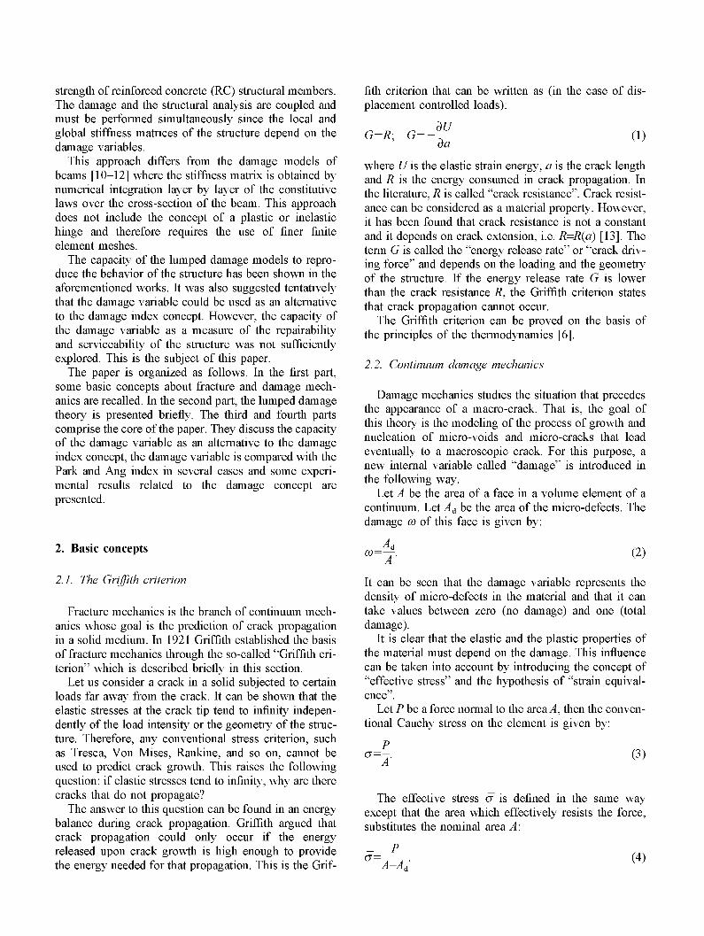
For 4 constant, the yield function (Eq. (12)) characterizes a bilinear behavior in the moment-rotation graph. When damage and plasticity evolve simultaneously, straight lines do not represent the behavior of the hinge (see Fig. 3).
Again, more sophisticated versions of the yield function are also possible from this basic model [7,8]. Comparison between tests and lumped damage models can be seen in [7-9,15,16],
4. The damage variable as a damage index
4.1. Performance limits
During a structural analysis with the model described in the previous section, the damage variables of each member of the frame must be computed since the stiffness matrix of the structure depends on them. However,
a B ©
Constant damage
Variable damage
GCA
Plastic Rotation Fig. 3. Moment as a function of the plastic rotation in the lumped damage model.
there are some questions that arise immediately. For a given set of damage values, can the structure still be safely used? Must it be repaired? These are the questions that the concept of damage index tries to answer.
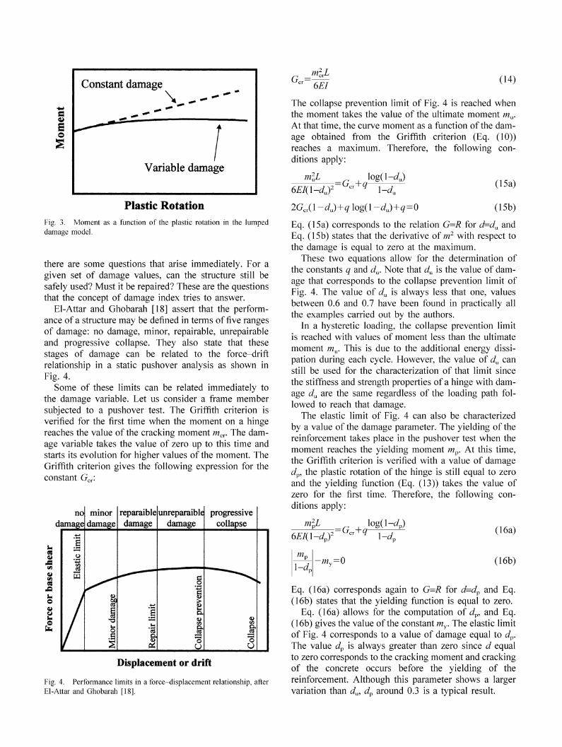
El-Attar and Ghobarah [18] assert that the performance of a structure may be defined in terms of five ranges of damage: no damage, minor, repairable, unrepairable and progressive collapse. They also state that these stages of damage can be related to the force-drift relationship in a static pushover analysis as shown in Fig. 4.
Some of these limits can be related immediately to the damage variable. Let us consider a frame member subjected to a pushover test. The Griffith criterion is verified for the first time when the moment on a hinge reaches the value of the cracking moment mcr. The damage variable takes the value of zero up to this time and starts its evolution for higher values of the moment. The Griffith criterion gives the following expression for the constant G •
no damage
eg
a
68 £2
© 4>
© *H
1 o
% 55
minor damage
ft 8P
o .3
reparaible damage
+-»
s u a
unreparaible damage
c o 1 t a ST
U
progressive collapse
9< C3
15
Displacement or drift
Fig. 4. Performance limits in a force-displacement relationship, after El-Attar and Ghobarah [18].
~ 6EI (14)
The collapse prevention limit of Fig. 4 is reached when the moment takes the value of the ultimate moment mu. At that time, the curve moment as a function of the damage obtained from the Griffith criterion (Eq. (10)) reaches a maximum. Therefore, the following conditions apply:
mlL
6EI(l-du)2 --Gcr+q
logO-dJ
\-dn
2Gcr(\-du)+q\og(\-du)+q = 0
(15a)
(15b)
Eq. (15a) corresponds to the relation G=R for d=du and Eq. (15b) states that the derivative of m2 with respect to the damage is equal to zero at the maximum.
These two equations allow for the determination of the constants q and du. Note that du is the value of damage that corresponds to the collapse prevention limit of Fig. 4. The value of du is always less that one, values between 0.6 and 0.7 have been found in practically all the examples carried out by the authors.
In a hysteretic loading, the collapse prevention limit is reached with values of moment less than the ultimate moment mu. This is due to the additional energy dissipation during each cycle. However, the value of du can still be used for the characterization of that limit since the stiffness and strength properties of a hinge with damage du are the same regardless of the loading path followed to reach that damage.
The elastic limit of Fig. 4 can also be characterized by a value of the damage parameter. The yielding of the reinforcement takes place in the pushover test when the moment reaches the yielding moment mp. At this time, the Griffith criterion is verified with a value of damage dp, the plastic rotation of the hinge is still equal to zero and the yielding function (Eq. (13)) takes the value of zero for the first time. Therefore, the following conditions apply:
m\l
6EI{\-dJ = Gcr+q
log(l-^p) 1-cL
m„ \-dr
-my=0
(16a)
(16b)
Eq. (16a) corresponds again to G=R for d=dp and Eq. (16b) states that the yielding function is equal to zero.
Eq. (16a) allows for the computation of dp, and Eq. (16b) gives the value of the constant my. The elastic limit of Fig. 4 corresponds to a value of damage equal to dp. The value dp is always greater than zero since d equal to zero corresponds to the cracking moment and cracking of the concrete occurs before the yielding of the reinforcement. Although this parameter shows a larger variation than du, dp around 0.3 is a typical result.
It is, therefore, clear that the elastic and the collapse prevention limits can be characterized by the values dv
and du respectively. These parameters can be computed if the cracking, yielding and ultimate moments of the member's cross-section are known. These damage values represent those limits even in the case of hyster-etic loadings with cyclic energy dissipation.
4.2. Relation between the damage variable and the Park and Ang index in monotonic cases
The Park and Ang index, as modified by Kunnath et al. [4], can be written as:
TV
7D=-^+energy—related term (17)
where ft is the ultimate plastic rotation. Under mono-tonic loading, the energy-related term can be neglected. Then, the plastic rotation is given by: ft=IDft. Substitution of Eq. (17) in the yielding function (Eq. (13)) gives if is equal to zero during plastic rotation evolution):
m
\^d --cIDft+my (18)
At the same time, the Griffith criterion (Eqs. (10) and (11)) states:
m
\^d
UEI -R(d) (19)
Eqs. (18) and (19) lead to the following relation:
Eq. (22), or Eq. (20), can be used to compute the damage index ID that corresponds to a value of the damage variable and vice versa. For instance, they can be used to obtain an estimate of the repair limit in Fig. 4. It is often accepted that values of ID around 0.4 characterize the repair limit [18]. Eq. (22) can be used to compute the value of damage that corresponds to this repair limit.
4.3. Normalization of the damage variable
The use of the damage variable d as a damage index presents some drawbacks: the performance limits du and dv are not the same for different structures, the elastic limit is not represented by zero and one does not correspond to the collapse limit. In order to overcome these disadvantages, the following repairability index RI can be used instead of the damage variable d.
RI= d^-d
<frdv
(23)
where d is the damage on the hinge. Note that the repair-ability index is simply a normalization of the damage variable.
A repairability index of one or greater means that there is no damage or that reparation is not needed. A repairability index of zero characterizes the collapse of the hinge in the sense of Fig. 4.
5. Experimental analysis
5.1. Measure of the damage variable in a monotonic test
In= eft I UEI
R(d)—m (20)
/
Finally, the constant c and the ultimate plastic rotation can be eliminated from Eq. (20) taking into account that the yielding function (Eq. (13)) establishes the following relationship between ft and the ultimate moment mu.
1-J„ eft
Therefore
-TTL, (21)
/ D =
I UEI -R(d)—my
I m„
1-4, -m. (22)
In order to verify the concepts presented in the previous section, some experimental tests were carried out in the laboratory. An important aspect of this experimental program is the measure of the damage variable. A procedure that can be used in monotonic tests is now described.
A specimen that represents a beam-column joint was subjected to the boundary conditions and the displacement-controlled loading indicated in Fig. 5a. Fig. 6 shows a plot of force against deflection obtained in one of the tests. The lumped plasticity model of those tests is shown in Fig. 5b.
For the case under consideration the following conditions apply:
m, = 0; 4 = 0 ; ft=0; mj=pL/2; dj=d; t
L,Vj (24)
-LP
~L
where p is the force on the column, t the deflection, tp

(a)
Fig. 5. (a) Beam-column joint, (b) Lumped plasticity model of the test.
is the permanent or plastic deflection, the index i corresponds to the simply supported end and the index j represents the node in the middle of the specimen. The application of Eq. (7) plus the boundary conditions (Eq. (24)) lead to the following relation between force and deflection:
p=Z(d)(t—tp) where Z(d)=(l—d)Z0; Z0= 6EI
T3 (25)
The term Z(d) corresponds to the slope of the elastic unloading. From Eq. (25), the following equation can be derived:
d=\-Z0
(26)
This equation can be used to measure damage evolution during the test, since the slope Z can be measured from the graph in Fig. 6. This kind of procedure was first used
to measure the continuum damage variable co during a uniaxial test [19].
5.2. Comparison with the Park and Ang index
In this section both indices are compared in two cases. The first test corresponds to the specimen represented in Fig. 5. The details of the specimen, reinforcement and loading are described in [20].
The specimen was loaded up to its total collapse (see Fig. 6). The values of the damage at each elastic unloading were computed, using Eq. (26), with the slopes of the lines indicated in Fig. 6 (lines 1 to 8). The line marked as 0 was used for the measure of the value of Z0 in Eq. (26). This value is Z0=26 kN/mm. These results are shown in the third column of Table 1. The maximum deflection after each unloading is indicated in the second column. The repairability and the Park and Ang indices are also shown. These values were obtained from the experimental results using Eqs. (23) and (17) respectively. In the first case, the value of dp was taken as 0.39 and du was 0.60. For the Park and Ang index,
Table 1 Values of damage
Line
0 1 2 3 4 5 6 7 8
Displacement Damage (mm)
_ 2.52 5.44 9.72
15.33 20.56 25.59 30.81 40.63
0 0.17 0.39 0.44 0.49 0.51 0.53 0.56 0.60
Repairability index
>1 >1
1 0.77 0.51 0.43 0.32 0.20 0
Park and Ang index
0 0.02 0.05 0.13 0.28 0.42 0.57 0.72 1
10 20 30 40 50 displacement (mm)
Fig. 6. Force vs. deflection in the reference test.

30 40 50
displacement (mm)
Fig. 7. Numerical simulation of the test reported in Fig. 6.
80
the value of 0£ was computed with the plastic displacement measured with the unloading number 8.
The numerical simulation of this test is shown in Fig. 7. This simulation was carried out with the model described in this paper. The specimen properties (EI, mu, mp and mcr) were not computed but taken directly from the experimental results. Fig. 8 indicates the evolution of the damage variable, the repairability index and the Park and Ang index during the simulation. Table 1 and Fig. 8 can be used to compare numerical and experimental results.
In view of the results observed in the test and the simulation presented in this section, it seems that a value of RI-0.5-0.6 characterizes the repair limit of Fig. 4. This result is presented on the basis of the commonly accepted limit for the Park and Ang index.
The second example corresponds to a cyclic test
reported in the literature. Fig. 9 shows the results of the test [21]. The numerical simulation of the test was carried out with a generalization of the model presented in this paper that is described in [17]. The results of the simulation are shown in Fig. 10. Fig. 11 indicates the evolution during the simulation of the damage variable, the repairability index and the modified Park and Ang index. Specifically, it used the version of the Park and Ang index proposed by Kunnath et al. [4]. The value of the parameter beta used in the simulation is 0.24.
5.3. Behavior of repaired specimens
Several specimens, of the same type as the one described in Fig. 5, were loaded up to produce different degrees of damage, as shown in Figs. 13 and 14. After this loading, the specimens were repaired using a tech-
1
0,9
0,8
0,7
0,6 an
'% 0,5 (3
" 0,4
0,3
0,2
0,1
0 ] (
Damage variable
h1*- -L 11%.- J . . . —i—^
> 5 10 - ^-i-
15
Park & Ang index > ^
^ \ ^ Reparability index
1 ' 'i i i" ' i mi|r*fc { 20 25 30 35 40 4,
Displacement (m.m.)
Fig. 8. Evolution of the damage indices during the numerical simulation.

90.01
6Q0h
30.0h
-30.0H
S\i,rruQS W ^ -
- 6 0 0 h 0 ; 3 3 ot 44.5mm b:5 3 at 57mm c: 1*2 ot 57mm 1% 25.4 mm
-90.01
7..... Jfe. I L.. [JHr\^ 2.5
' displacement -in
-63.0 -42.0 -210 0 210 displacement-mm
42.0 630
Fig. 9. Force as a function of the displacement in an RC specimen, after Scribner and Wight [21].
z •6 n 0
-63 -42 -21 0 21 42
displacement -mm
63
U
8 0,8 1 O)
c 0,6
0,4
0,2
Reparability index
Park & Ang index
Damage variable
Fig. 10. Numerical simulation of the test presented in Fig. 9.
pseudo-time
Fig. 11. Damage evolution during the simulation.
nique commonly used in the reparation of bridges [22]. The procedure consisted basically in the closure of the concrete cracks with an epoxy resin and the strengthening of the structure with a carbon fibre reinforced polymer strip (see Fig. 12).
After reparation, the specimens were again loaded up to strip failure. Figs. 13 and 14 show the results of two tests. In these figures, the behavior of the reference (the same as that indicated in Fig. 6) and the behavior of the
TT5& J m We A
Composite strip Fig. 12. Strengthening with a composite strip.

120,00
100,00
after reparation
- before reparation reference
S
30 40 50
displacement (mm)
Fig. 13. Behavior of a repaired specimen.
60 70 80
O 80
a
30 40
displacement (mm)
Fig. 14. Behavior of a repaired specimen.
specimen before reparation are also shown. Note that Fig. 13 corresponds to a specimen that was pre-loaded up to the reference line number 4 and the curve in Fig. 14 corresponds to a specimen that was loaded up to the line 5. In the first case the pre-load is within the repair limit, in the second it is just outside the limit.
It can be seen that the behavior of both specimens is similar, and is independent of the previous damage state. That is, as far as the strengthening is physically possible, the repaired specimen has a much higher strength. However, with relatively low deformations the strip is pulled away from the concrete. Thus, the remaining ductility of the structural member depends mainly on the state of damage of the pre-repaired specimen. It is, therefore, important to limit the damage state up to which reparation is allowed.
6. Final remarks and conclusions
It has been shown that a damage variable, after suitable normalization, can be used as a damage index. This new index is applicable only to models within the framework of lumped damage mechanics. In this particular case, the values needed for an adequate normalization of the damage are the parameters du and dp.
The elastic and progressive collapse limits are very clearly defined. However, the repair limit is a somewhat subjective concept. The limit that was proposed in this paper is simply an adaptation of the accepted values for the Park and Ang index, but it seems clear that this limit may depend on the specific repair strategy selected.
The uncoupled, or two-step, approach remains, of course, useful since it allows the use of simple and fast

structural models in the damage assessment of a structure. However, it is often necessary to use more sophisticated models with stiffness and strength degradation. In these cases, it should be possible to compute damage measures directly from the state of the structure at each step of the analysis. These damage variables, which are specific for each model, are more representative of the predicted state of the structure than the general damage indices.
Acknowledgements
This work was sponsored by grants from the Minis-terio de Education y Cultura, Spain, CONICIT, Venezuela, and CDCHT, University of Los Andes, Venezuela.
References
[1] Aguiar R, Barbat AH. Indices de dano sismico en edificios de hormigon armado (in Spanish). Hormigon Acero 1998;210:73-92.
[2] Park Y, Ang A. Mechanistic seismic damage model for reinforced concrete. J Struct Div ASCE 1985;111:722-39.
[3] Kunnath SK, Reinhorn AM, Abel JF. A computational tool for evaluation of seismic performance of reinforced concrete buildings. Comput Struct 1991;41(1): 157-73.
[4] Kunnath SK, Reinhorn AM, Lobo R. IDARC Version 3.0: a program for the inelastic damage analysis of reinforced concrete structures. National Center for Earthquake Engineering Research, Technical Report BCEER-92-0022, University of New York at Buffalo, 1992.
[5] Reinhorn AM, Valles RE. Damage evaluation in inelastic response of structures: a deterministic approach. National Center for Earthquake Engineering Research, Technical Report BCEER-95, University of New York at Buffalo, 1995.
[6] Lemaitre J, Chaboche J-L. Mechanics of solid materials. Paris: Dunod, 1988.
[7] Florez-Lopez J. Unilateral model of damage for RC frames. J Struct Eng ASCE 1995;121(12): 1765-72.
[8] Perera R, Carnicero A, Alarcon E, Gomez S. A damage model for seismic retrofitting of structures. In: Advances in civil and structural engineering computing for practice. Edinburgh: Civil-Comp Press, 1998:309-15.
[9] Perdomo M-E, Ramirez A, Florez-Lopez J. Simulation of damage in RC frames with variable axial forces. Earthquake Eng Struct Dyn 1999;28(3).
[10] Breysse D, Mazars J. Simplified approach of nonlinearity in R.C beams. ASCE J Struct Eng Div 1988;114:251-68.
[11] Lubliner J, Alves BK. A damage mechanics model for beams. Eur J Mech A/Solid 1994;13:189-213.
[12] Oiler S, Luccioni B, Barbat A. Un metodo de evaluation del dano sismico en estructuras de hormigon armado (in Spanish). Rev Int Metodos Numericos Calculo Disefio Ingenieria 1996;12(2):215-38.
[13] Broek D. Elementary engineering fracture mechanics. Martinus Nijhoff 1986.
[14] Florez-Lopez J. Frame analysis and continuum damage mechanics. J Eur Mech 1998;17(2).
[15] Cipollina A, Lopez-Inojosa A, Florez-Lopez J. A simplified damage mechanics approach to nonlinear analysis of frames. Comput Struct 1995;54(6): 1113-26.
[16] Thomson E, Bendito A, Florez-Lopez J. Simplified model of low cycle fatigue for RC frames. J Struct Eng ASCE 1998; 124(9).
[17] Picon R, Florez-Lopez J. Implementation en ABAQUS del mod-elo histeretico de dano considerando fatiga de bajo ciclaje para porticos de concreto armado (in Spanish). In: ler Congreso National de Ingenieria Sismica, Spain, 1999.
[18] El-Attar M, Ghobarah A. Performance based evaluation of reinforced concrete buildings. Eur Earthquake Eng 1998;12(2):22-9.
[19] Lemaitre J, Dufailly J. Damage measurements. Eng Fract Mech 1987;28(5/6):643-61.
[20] Recuero A, Gutierrez JP, Lopez C, De Diego A. Ensayos realiz-ados en el Instituto Eduardo Torroja sobre refuerzo con CFRP de nudos de union viga-columna danados por cargas laterales. Instituto de Ciencias de la Construction Eduardo Torroja, C.S.I.C, 1999.
[21] Scribner CF, Wight JK. Delaying shear strength decay in reinforced concrete flexural members and large load reversals. Report No UMEE 78R2, Ann Arbor (MI): Department of Civil Engineering, University of Michigan, 1978.
[22] Gomez MD, Sobrino JA. Refuerzo de estructuras de hormigon con materiales compuestos con fibras de carbono. Aplicacion al puente del Drago, Barcelona (in Spanish). Hormigon Acero 1998;210:73-92.