Taylor v. Canyon County Bd. of Comm'rs Respondent's Brief ...
Updated 2015
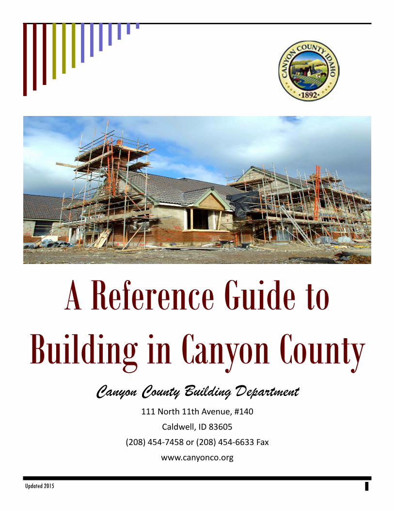
A Reference Guide to Building in Canyon County
Canyon County Building Department 111 North 11th Avenue, #140
Caldwell, ID 83605
(208) 454‐7458 or (208) 454‐6633 Fax
www.canyonco.org
Canyon County Building Department
This reference guide is intended to assist the building novice and the expert builder as well. Our hope is that we have provided a comprehensive guide to be used as a use-ful reference for your building projects. You may still have questions, in which case,
please contact us. We will be glad to assist you.
Canyon County Building Department Located across from the Canyon County Courthouse
111 North 11th Avenue, #140, Caldwell, ID 83605
Hours of Operation: 8:00 a.m. until 4:30 p.m.
Phone: (208) 454-7458 Fax: (208) 454-6633
Email: [email protected]
Or visit our website at
www.canyonco.org/dsd.aspx
All Electrical and Plumbing applications and inspections are Administered by the
State of Idaho, Building & Safety Division Please call (208) 334-3950 for
Additional Information on how to apply
We wish to give our sincere appreciation to My Building Permit.com for providing reference materials to create this document.

Updated 2015 3
Canyon County Building Department
Table of Contents
Topic Page Number
Permits—When Required…………………………………………………. 4
Basic Stairs…………………………………………………………………. 6
Guards (stairs) …………………………………………………………….. 8
Smoke Alarms …………………………………………………………….. 10
Basic Decks ……………………………………………………………….. 12
Garage Separation………………………………………………………... 17
Residential Emergency Escape & Rescue Openings…………………. 20
Notching & Boring Rafters / Joists / Studs ……………………………... 23
Fire Protection of Horizontal Venting…………………………………….. 26
Safety Glazing……………………………………………………………… 28
Typical Wall Framing………………………………………………………. 35
Wall Section & Basement…………………………………………………. 37
Site Plan Example…………………………………………………………. 38
Footings / Floor……………………………………………………………. 40
Roof Types - Typical Cross Section……………………………………. 42
Roof Framing Plan……………………………………………………….. 43
Sample Plan……………………………………………………………….. 44

Updated 2015 4
Canyon County Building Department When are Building Permits Required?
Page 1 of 2
Building and Mechanical Permits May Be Required.
Ask Before You Begin to Build
Commonly, No Building or Mechanical system can be constructed, enlarged, altered, repaired, moved, demolished or changed unless a
Building Permit has been issued.
Common Examples of When a Permit is Required
Carports
Decks more than 30” above grade
Dock repairs and additions
Exterior doors, windows and skylights that require a new
opening or larger opening.
Electrical Circuits and service
Fireplaces, wood-burning stoves and inserts
Garage conversions
Home-business conversions
Interior remodels
Guest Home
Fences over 7’ high
Furnaces
Gas Piping
Rockeries and retaining walls over 4’ in height
In-ground or above ground swimming pools and swim spas
4’ deep; or above ground prefabricated pools over 5,000
gallons
Re-roof involving structural elements, including but not lim-
ited to sheathing, skylights, change of roof pitch, addition or
relocation of mechanical units; and change of roof material
where the total weight exceeds 10 psf (pounds per square
foot)
Building permits are required on all new constructions that is
greater than 200 sq ft and/or is attached to another struc-
ture.
2009 IRC
Common Examples of when a Permit is Not Required
One-story detached accessory structures used as tool and
storage sheds; tree-supported play structures, playhouses,
with similar uses not exceeding 200. s.f. (Wall height of
10’ maximum.)
Fences not over 7’ high
Retaining walls or rockeries which are not over 4’ in height
measured from the bottom of the footing to the top of the
wall, unless supporting a surcharge or sloped ground (see
page 5)
Sidewalks, decks and driveways not more than 30” above
grade and not over a basement or story below.
Replacement of decking on docks and decks without re-
placement of any structural members
Painting, nonstructural siding, papering, tiling, carpeting,
cabinets, countertops, and similar finish work
Swings, slides and other playground equipment
Window awnings supported by an exterior wall which does
not project more than 54” and does not require additional
support
Bathroom and kitchen fixture replacements without plumb-
ing line modifications such a sinks and toilets
Appliance replacement in the same location without modi-
fication to gas, plumbing lines or electrical circuits such as
dishwashers, ranges, ovens, gas logs, washers and dry-
ers.
Portable swimming pools (under 5, 000 gallons)
Flag poles

Updated 2015 5
Canyon County Building Department
Permits When Required
Page 1 of 1
General Information: 1. Consult with your local planning department regarding required setbacks. 2. The intent of this Sheet is to address the requirements of when a Building Permit is required. For residential projects, please
contact your local building department regarding specific questions not addressed here or requiring further clarification.
Frost Depth of 24”
Updated 2015 6
Canyon County Building Department Construction Tip Sheet 1
Basic Stairs - 2012 IRC
Page 1 of 4
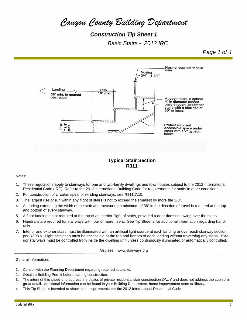
Typical Stair Section R311
Notes: 1. These regulations apply to stairways for one and two-family dwellings and townhouses subject to the 2012 International
Residential Code (IRC). Refer to the 2012 International Building Code for requirements for stairs in other conditions.
2. For construction of circular, spiral or winding stairways, see R311.7.10.
3. The largest rise or run within any flight of stairs is not to exceed the smallest by more the 3/8”.
4. A landing extending the width of the stair and measuring a minimum of 36” in the direction of travel is required at the top and bottom of every stairway.
5. A floor landing is not required at the top of an interior flight of stairs, provided a door does not swing over the stairs.
6. Handrails are required for stairways with four or more risers. See Tip Sheet 2 for additional information regarding hand-rails.
7. Interior and exterior stairs must be illuminated with an artificial light source at each landing or over each stairway section per R303.6. Light activation must be accessible at the top and bottom of each landing without traversing any steps. Exte-rior stairways must be controlled from inside the dwelling unit unless continuously illuminated or automatically controlled.
Also see: www.stairways.org
General Information: 1. Consult with the Planning Department regarding required setbacks. 2. Obtain a Building Permit before starting construction. 3. The intent of this sheet is to address the basics of private residential stair construction ONLY and does not address the subject in
great detail. Additional information can be found in your Building Department, home improvement store or library. 4. This Tip Sheet is intended to show code requirements per the 2012 International Residential Code.

Updated 2015 7
Canyon County Building Department Construction Tip Sheet 1
Basic Stairs
Page 2 of 4

Updated 2015 8
Canyon County Building Department Construction Tip Sheet 2
Basic Stairs - Guards
Page 3 of 4
General Information: 1. Consult with the Planning Department regarding required setbacks. 2. Obtain a Building Permit before starting construction 3. The intent of this sheet is to address the basics of private residential stair construction ONLY and does not address
the subject in great detail. Additional information is available in your Building Department, home improvement store or library.
4. This Tip Sheet is intended to show code requirements per the 2012 International Residential Code (IRC).
Updated 2015 9
Canyon County Building Department Construction Tip Sheet 2
Basic Stairs - Handrails
Page 4 of 4
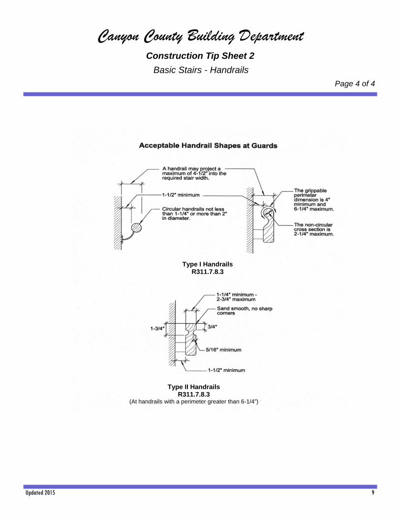
Type I Handrails R311.7.8.3
Type II Handrails R311.7.8.3
(At handrails with a perimeter greater than 6-1/4”)
Updated 2015 10
Canyon County Building Department Construction Tip Sheet 3
Smoke Alarms / Detectors
Page 1 of 2
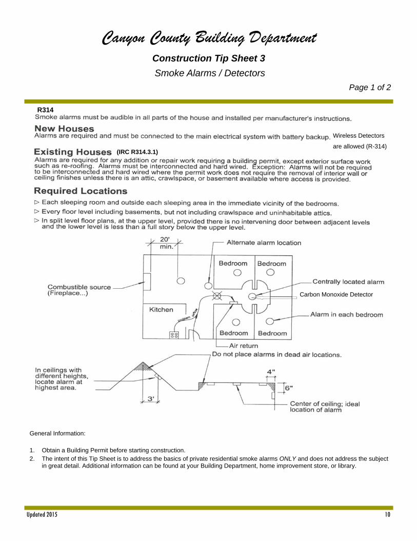
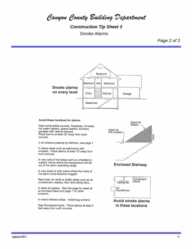
General Information: 1. Obtain a Building Permit before starting construction. 2. The intent of this Tip Sheet is to address the basics of private residential smoke alarms ONLY and does not address the subject
in great detail. Additional information can be found at your Building Department, home improvement store, or library.
R314
Wireless Detectors
are allowed (R-314) (IRC R314.3.1)
Carbon Monoxide Detector
Updated 2015 11
Canyon County Building Department Construction Tip Sheet 3
Smoke Alarms
Page 2 of 2
Updated 2015 12
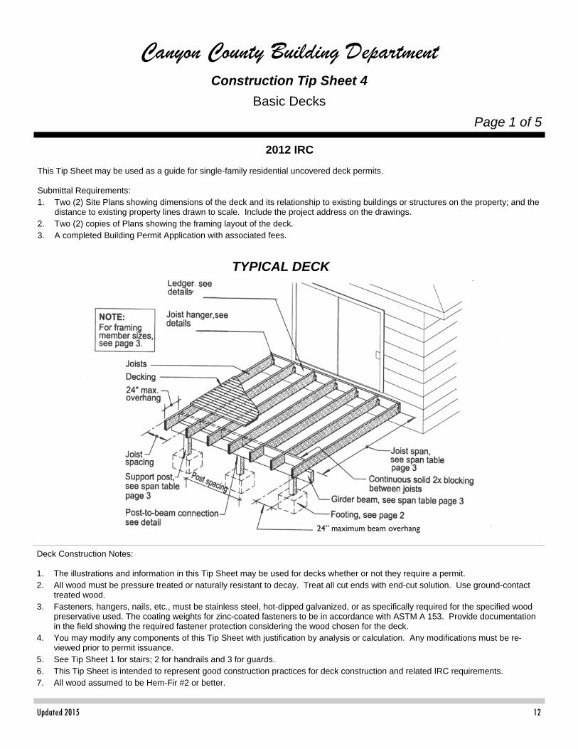
Canyon County Building Department Construction Tip Sheet 4
Basic Decks
Page 1 of 5
2012 IRC This Tip Sheet may be used as a guide for single-family residential uncovered deck permits. Submittal Requirements: 1. Two (2) Site Plans showing dimensions of the deck and its relationship to existing buildings or structures on the property; and the
distance to existing property lines drawn to scale. Include the project address on the drawings. 2. Two (2) copies of Plans showing the framing layout of the deck. 3. A completed Building Permit Application with associated fees.
Deck Construction Notes: 1. The illustrations and information in this Tip Sheet may be used for decks whether or not they require a permit. 2. All wood must be pressure treated or naturally resistant to decay. Treat all cut ends with end-cut solution. Use ground-contact
treated wood. 3. Fasteners, hangers, nails, etc., must be stainless steel, hot-dipped galvanized, or as specifically required for the specified wood
preservative used. The coating weights for zinc-coated fasteners to be in accordance with ASTM A 153. Provide documentation in the field showing the required fastener protection considering the wood chosen for the deck.
4. You may modify any components of this Tip Sheet with justification by analysis or calculation. Any modifications must be re-viewed prior to permit issuance.
5. See Tip Sheet 1 for stairs; 2 for handrails and 3 for guards. 6. This Tip Sheet is intended to represent good construction practices for deck construction and related IRC requirements. 7. All wood assumed to be Hem-Fir #2 or better.
TYPICAL DECK
24” maximum beam overhang
Updated 2015 13
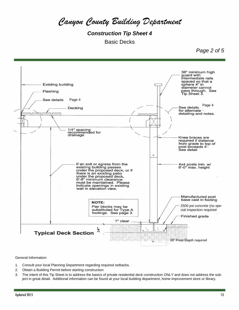
Canyon County Building Department Construction Tip Sheet 4
Basic Decks
Page 2 of 5
Page 4
Page 4
2500 psi concrete (no spe-cial inspection required
General Information:
1. Consult your local Planning Department regarding required setbacks. 2. Obtain a Building Permit before starting construction 3. The intent of this Tip Sheet is to address the basics of private residential deck construction ONLY and does not address the sub-
ject in great detail. Additional information can be found at your local building department, home improvement store or library.
24”
24” Frost Depth required

Updated 2015 14
Canyon County Building Department Construction Tip Sheet 4
Basic Decks
Page 3 of 5
Span Table Footing Schedule for Outside Decks
Spans based on use of No. 2 Hem-Fir or better
50 p.s.f. loading (10 p.s.f. Dead Load + 40 p.s.f. Live Load)
Beam spans and footings assume maximum 24” overhand
Joist Size Spacing of
Joists Max Span of Joist
3/8” x 4 1/2” Lag screw max. spac-ing on 2x ledger
4 x 6 Footing 4 x 8 Footing 4 x 10 Footing
2 x 6 @ 12 in @ 16 in @ 24 in
9 ft - 10 in 8 ft - 9 in 7 ft - 1 in
5 in 6 in 7 in
5 ft - 5 in 5 ft - 8 in
B B B
7 ft - 2 in 7 ft - 6 in 8 ft - 0 in
B B B
8 ft - 10 in 9 ft - 2 in 9 ft - 10 in
C B B
2 x 8 @ 12 in @16 in @ 24 in
12 ft - 9 in 11 ft - 1 in 9 ft - 0 in
4 in 4 in 5 in
4 ft - 11 in 5 ft - 2 in 5 ft - 7 in
B A B
6 ft - 6 in 6 ft - 11 in 7 ft - 5 in
B B B
8 ft - 0 in 8 ft - 5 in 9 ft - 1 in
B C B
Max. span of girder beams between posts / footing type
2 x 10 @ 12 in @ 16 in @ 24 in
15 ft - 7 in 13 ft - 6 in 11 ft - 0 in
3 in 3 in 4 in
4 ft - 7 in 4 ft - 10 in 5 ft - 3 in
B B A
6 ft - 0 in 6 ft - 5 in 6 ft - 11 in
B B B
7 ft - 5 in 7 ft - 10 in 8 ft - 5 in
C C B
FOOTING TYPES TYPE SIZE NOTE:
A 12” x 12” x 24”
B 16” x 16” x 24”
C 18” x 18” x 24”
*Pouring based on assumed soil bearing pressure of 2000 p.s.f. Contact your jurisdiction for additional restrictions
Deck construction connections
All fasteners, nails, bolts, screws, etc. must be corrosion resistant. See Deck construction Note 3, page 1.
Follow manufacturer’s instructions for timber connectors.
1 Joist on deck beam; toenail each end (3) 8d
2 Bridging or blocking to joist; toenail ea. Side, ea. end (3) 8d
3 2x decking to joist or deck beam; blind and face nail (2)16d
Connections

Updated 2015 15
Canyon County Building Department Construction Tip Sheet 4
Basic Decks
Page 4 of 5
Updated 2015 16
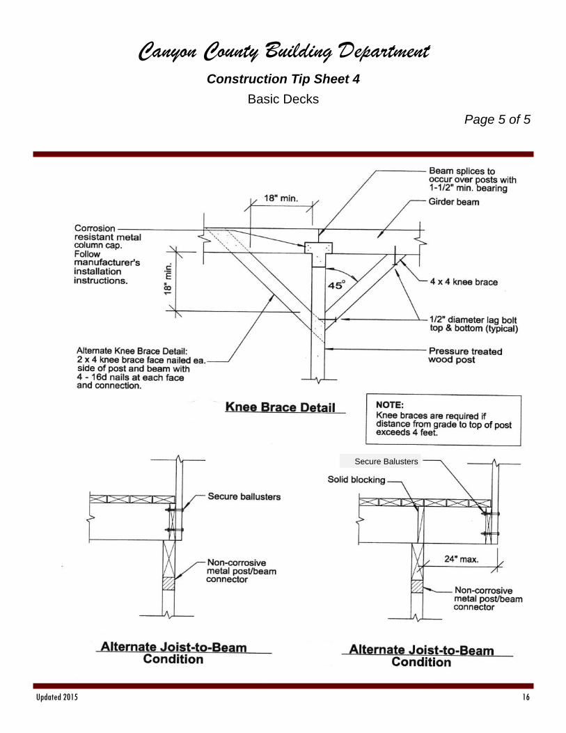
Canyon County Building Department Construction Tip Sheet 4
Basic Decks
Page 5 of 5
Secure Balusters
Updated 2015 17
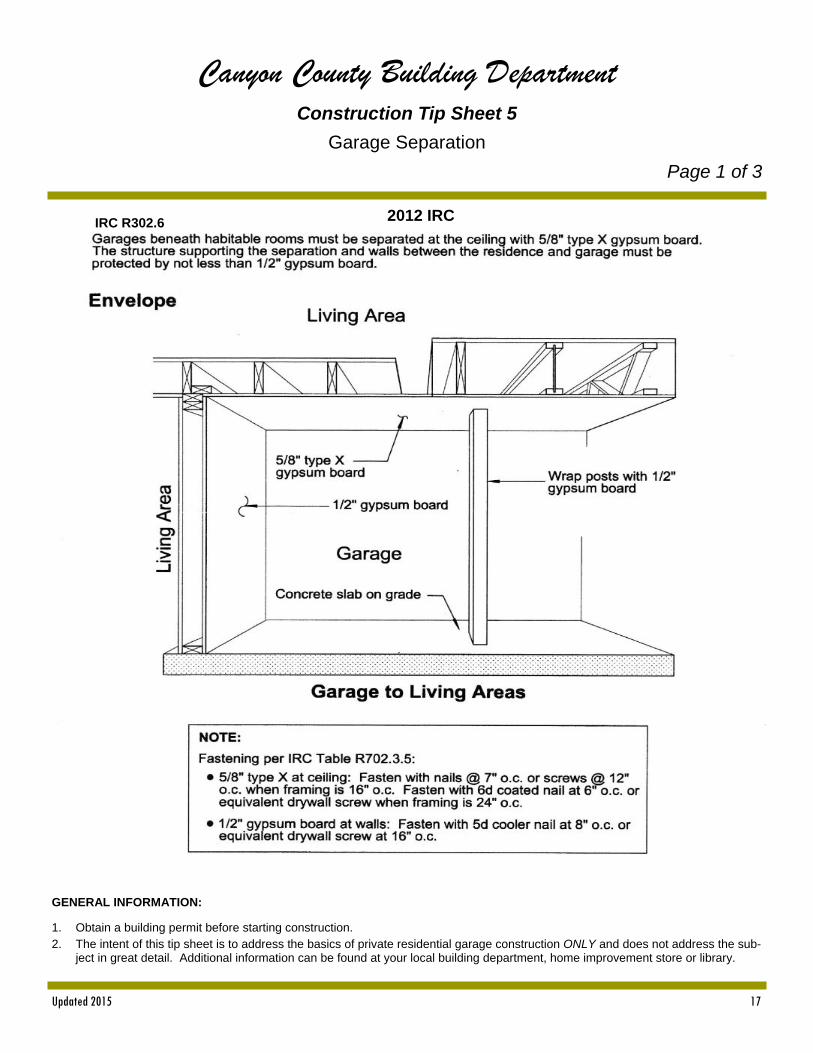
Canyon County Building Department Construction Tip Sheet 5
Garage Separation
Page 1 of 3
GENERAL INFORMATION:
1. Obtain a building permit before starting construction. 2. The intent of this tip sheet is to address the basics of private residential garage construction ONLY and does not address the sub-
ject in great detail. Additional information can be found at your local building department, home improvement store or library.
2012 IRC IRC R302.6

Updated 2015 18
Canyon County Building Department Construction Tip Sheet 5
Garage Separation
Page 2 of 3
Fire Collar on Pipe Penetrations
These Doors will be equipped with a self-closing device. (IRC R302.5.1)
Updated 2015 19
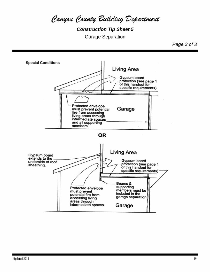
Canyon County Building Department Construction Tip Sheet 5
Garage Separation
Page 3 of 3
Special Conditions
Updated 2015 20
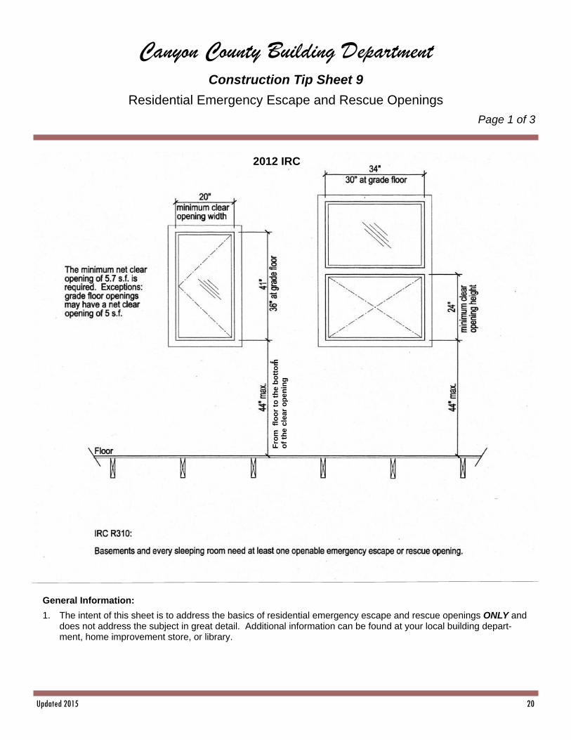
Canyon County Building Department Construction Tip Sheet 9
Residential Emergency Escape and Rescue Openings
Page 1 of 3
2012 IRC
General Information:
1. The intent of this sheet is to address the basics of residential emergency escape and rescue openings ONLY and does not address the subject in great detail. Additional information can be found at your local building depart-ment, home improvement store, or library.
Fro
m
flo
or
to t
he
bo
tto
m
of
the
clea
r o
pe
nin
g

Updated 2015 21
Canyon County Building Department Construction Tip Sheet 9
Residential Emergency Escape and Rescue Openings
Page 2 of 3
Updated 2015 22
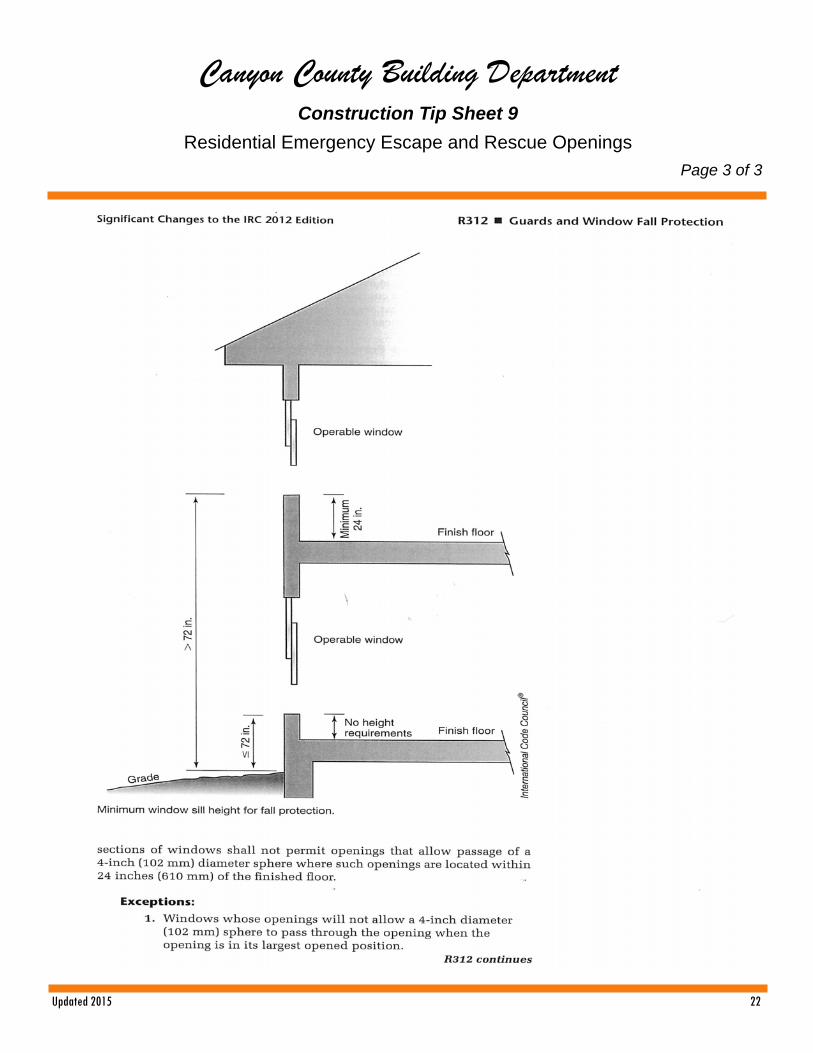
Canyon County Building Department Construction Tip Sheet 9
Residential Emergency Escape and Rescue Openings
Page 3 of 3
Updated 2015 23
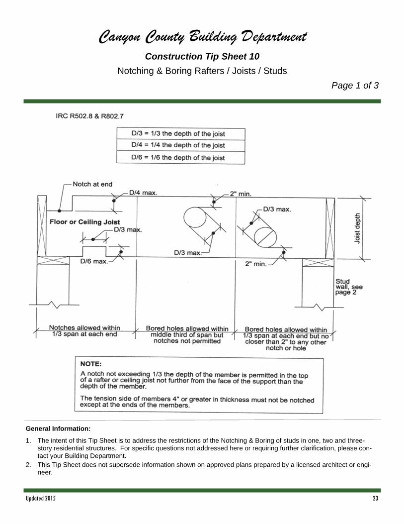
Canyon County Building Department Construction Tip Sheet 10
Notching & Boring Rafters / Joists / Studs
Page 1 of 3
General Information:
1. The intent of this Tip Sheet is to address the restrictions of the Notching & Boring of studs in one, two and three-story residential structures. For specific questions not addressed here or requiring further clarification, please con-tact your Building Department.
2. This Tip Sheet does not supersede information shown on approved plans prepared by a licensed architect or engi-neer.
Updated 2015 24
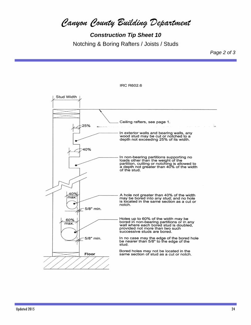
Canyon County Building Department Construction Tip Sheet 10
Notching & Boring Rafters / Joists / Studs
Page 2 of 3

Updated 2015 25
Canyon County Building Department Construction Tip Sheet 10
Notching & Boring Rafters / Joists / Studs
Page 3 of 3
Typical Notching and Boring Details
Updated 2015 26
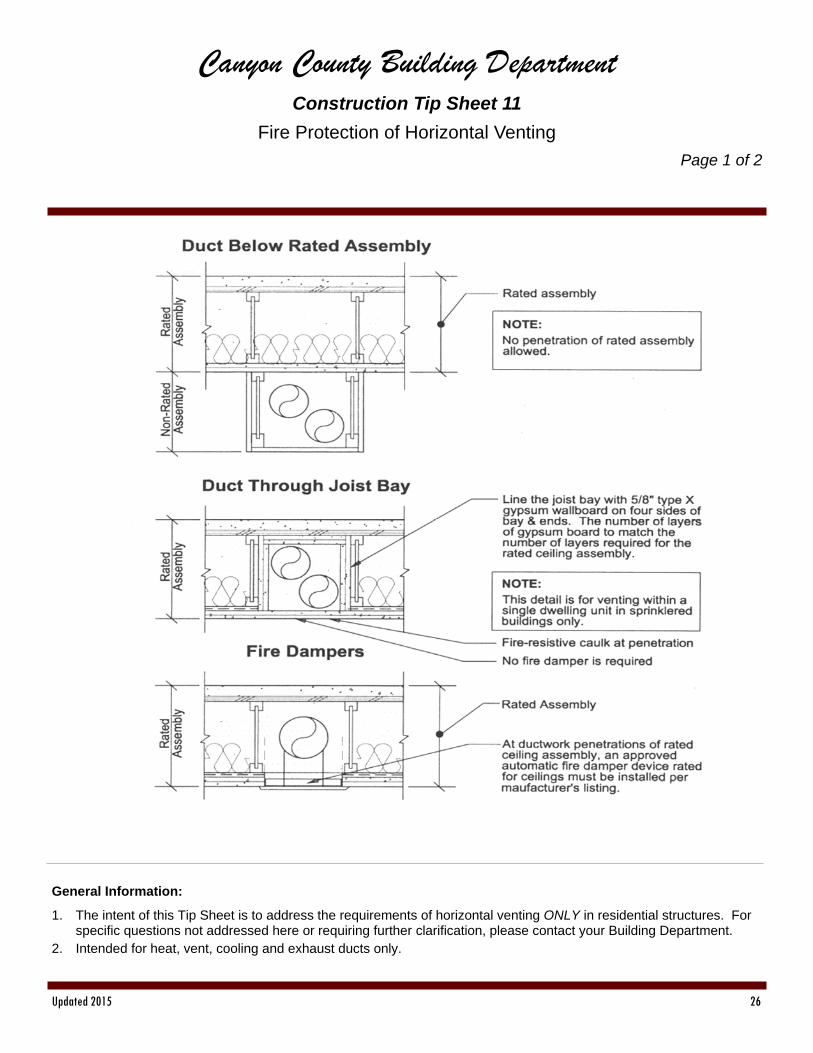
Canyon County Building Department Construction Tip Sheet 11
Fire Protection of Horizontal Venting
Page 1 of 2
General Information:
1. The intent of this Tip Sheet is to address the requirements of horizontal venting ONLY in residential structures. For specific questions not addressed here or requiring further clarification, please contact your Building Department.
2. Intended for heat, vent, cooling and exhaust ducts only.
Updated 2015 27
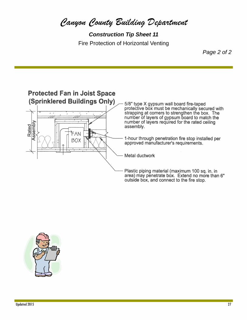
Canyon County Building Department Construction Tip Sheet 11
Fire Protection of Horizontal Venting
Page 2 of 2
Updated 2015 28
Canyon County Building Department Construction Tip Sheet 12
Safety Glazing
Page 1 of 7
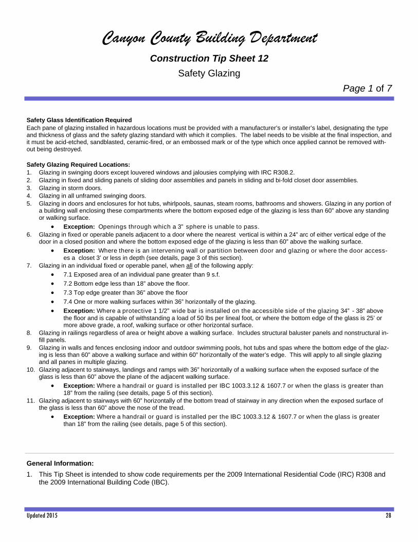
Safety Glass Identification Required Each pane of glazing installed in hazardous locations must be provided with a manufacturer’s or installer’s label, designating the type and thickness of glass and the safety glazing standard with which it complies. The label needs to be visible at the final inspection, and it must be acid-etched, sandblasted, ceramic-fired, or an embossed mark or of the type which once applied cannot be removed with-out being destroyed. Safety Glazing Required Locations: 1. Glazing in swinging doors except louvered windows and jalousies complying with IRC R308.2. 2. Glazing in fixed and sliding panels of sliding door assemblies and panels in sliding and bi-fold closet door assemblies. 3. Glazing in storm doors. 4. Glazing in all unframed swinging doors. 5. Glazing in doors and enclosures for hot tubs, whirlpools, saunas, steam rooms, bathrooms and showers. Glazing in any portion of
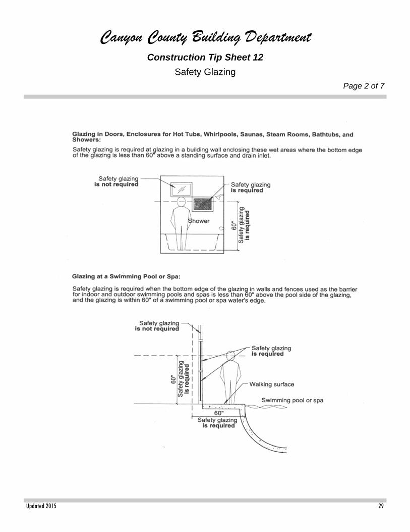
a building wall enclosing these compartments where the bottom exposed edge of the glazing is less than 60” above any standing or walking surface.
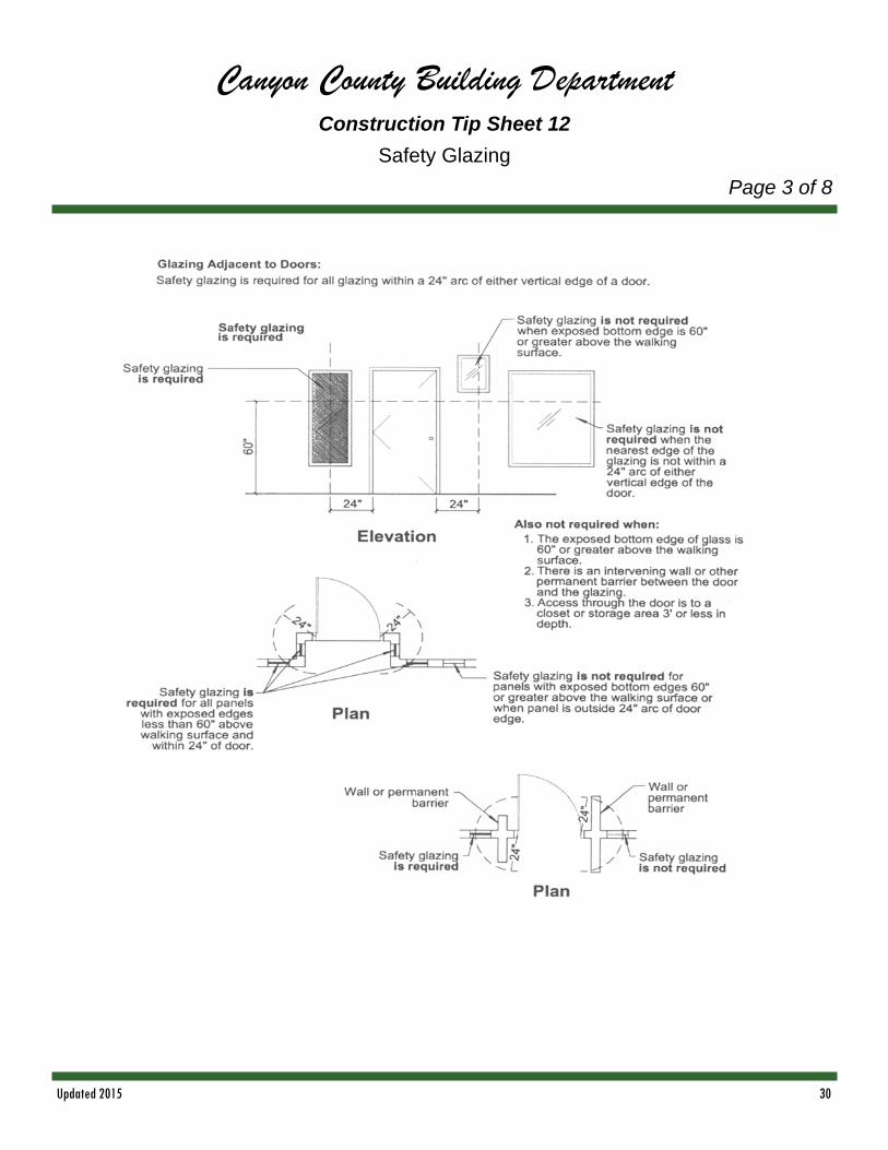
Exception: Openings through which a 3” sphere is unable to pass. 6. Glazing in fixed or operable panels adjacent to a door where the nearest vertical is within a 24” arc of either vertical edge of the
door in a closed position and where the bottom exposed edge of the glazing is less than 60” above the walking surface.
Exception: Where there is an intervening wall or partition between door and glazing or where the door access-es a closet 3’ or less in depth (see details, page 3 of this section).
7. Glazing in an individual fixed or operable panel, when all of the following apply:
7.1 Exposed area of an individual pane greater than 9 s.f.
7.2 Bottom edge less than 18” above the floor.
7.3 Top edge greater than 36” above the floor
7.4 One or more walking surfaces within 36” horizontally of the glazing.
Exception: Where a protective 1 1/2” wide bar is installed on the accessible side of the glazing 34” - 38” above the floor and is capable of withstanding a load of 50 lbs per lineal foot, or where the bottom edge of the glass is 25’ or more above grade, a roof, walking surface or other horizontal surface.
8. Glazing in railings regardless of area or height above a walking surface. Includes structural baluster panels and nonstructural in-fill panels.
9. Glazing in walls and fences enclosing indoor and outdoor swimming pools, hot tubs and spas where the bottom edge of the glaz-ing is less than 60” above a walking surface and within 60” horizontally of the water’s edge. This will apply to all single glazing and all panes in multiple glazing.
10. Glazing adjacent to stairways, landings and ramps with 36” horizontally of a walking surface when the exposed surface of the glass is less than 60” above the plane of the adjacent walking surface.
Exception: Where a handrail or guard is installed per IBC 1003.3.12 & 1607.7 or when the glass is greater than 18” from the railing (see details, page 5 of this section).
11. Glazing adjacent to stairways with 60” horizontally of the bottom tread of stairway in any direction when the exposed surface of the glass is less than 60” above the nose of the tread.
Exception: Where a handrail or guard is installed per the IBC 1003.3.12 & 1607.7 or when the glass is greater than 18” from the railing (see details, page 5 of this section).
General Information:
1. This Tip Sheet is intended to show code requirements per the 2009 International Residential Code (IRC) R308 and the 2009 International Building Code (IBC).
Updated 2015 29
Canyon County Building Department Construction Tip Sheet 12
Safety Glazing
Page 2 of 7
Updated 2015 30
Canyon County Building Department Construction Tip Sheet 12
Safety Glazing
Page 3 of 8

Updated 2015 31
Canyon County Building Department Construction Tip Sheet 12
Safety Glazing
Page 4 of 7

Updated 2015 32
Canyon County Building Department Construction Tip Sheet 12
Safety Glazing
Page 5 of 7
Updated 2015 33
Canyon County Building Department Construction Tip Sheet 12
Safety Glazing
Page 6 of 7

Updated 2015 34
Canyon County Building Department Construction Tip Sheet 12
Safety Glazing
Page 7 of 7
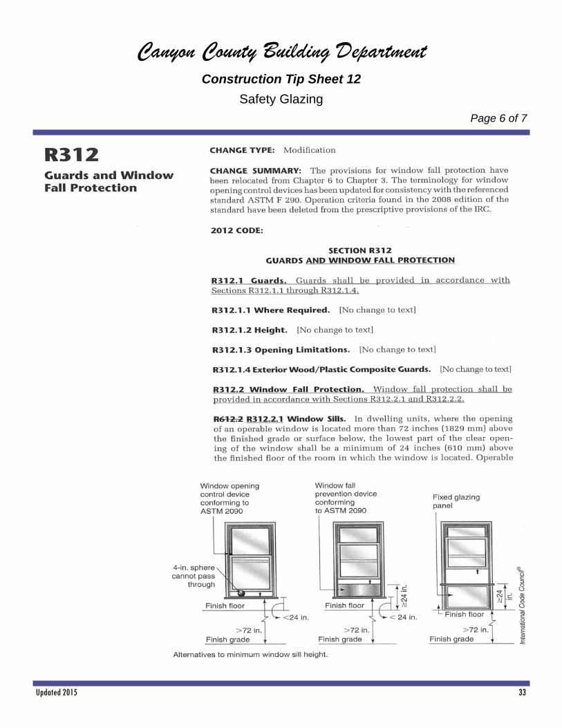
Significant Changes to the IRC 2012 Edition R308.4.7 Glazing Adjacent to the Bottom Stair Landing CHANGE SIGNIFICANCE: In residential occupancies, the greatest risk for a fall into glazing causing injury occurs at the bottom of stairways and the code has always defined the locations adjacent to bottom landings as hazardous locations. These provisions have undergone modifica-tion to clarify their intent and application, and provide consistency with the other safety glazing provisions. Item 8 in the list of hazardous loca-tions related to glazing becomes Subsection R308.4.7 in the 2012 IRC. The title of this subsection clarifies that it is glazing adjacent to the bot-tom landing that is being regulated, not glazing adjacent to the stairway. Similar to the stairway provisions in the previous item, the exception is more appropriately located in the main rule of this subsection. Previously, the rule stated that the glazing (other than safety glazing) required installation at least 60 inches above the walking surface. Exception 2 to the rule allowed installations less than 60 inches above the walking surface without requiring safety glazing provided a solid wall or panel protected the glazing to a height of 34 to 36 inches. The intent was that a window installed in a wall with the bottom exposed edge of the glazing at least 34 inches above the walking surface was not considered to be in a hazardous location. Because the standard installation is a window that is installed in a wall, the exception becomes the rule for the 2012 edi-tion of the IRC. The references to stairways in Subsection R308.4.6 contains information related to glazing near stairways, and it was not thought necessary to repeat the requirements in the subsequent subsection. The previous range of 34 to 36 inches shown in the exception in-
tended to correspond to the minimum heights of handrails and guards, respectively, but implied to some that there was a maximum height limit. A range of dimensions is confusing in this case, and the new code now sets a minimum height of 36 inches to correspond to the guard require-ments. Therefore, where the bottom exposed edge of the glazing adjacent to the landing is less than 36 inches above the walking surface and the glazing is within 60 inches of the bottom stair nosing, it is considered a hazardous location and safety glazing is required. Conversely, satis-fying either of the following conditions means the glazing at the bottom landing is not considered to be in a hazardous location and therefore does not require safety glazing:
The bottom exposed edge of the glazing is 36 inches or greater above the walking surface.
The glazing is greater than 60 inches from the nosing of the bottom tread of the stairway measured horizontally.
The modified provisions for glazing near a bottom landing differ from those for glazing adjacent to stairways in one significant way. Glazing adjacent a stairway that is less than 36 inches above the tread may be protected by a single rail meeting the prescribed load and dimension requirements or be protected by a guard. When so protected, the glazing is not considered to be in a hazardous location and does not require safety glazing. This exception does not apply to glazing near a bottom landing. To eliminate the need for safety glazing requires both a guard and a horizontal clearance of 18 inches between the guard and the glazing. The 18-inch requirement has been deleted from the provisions related to glazing at the side of a stairway.
Revision of these provisions clarifies the meaning, provides objectively measurable dimensions, and brings consistency to the application of glazing requirements in the vicinity of the landing at the bottom of stairways.

Updated 2015 35
Canyon County Building Department Construction Tip Sheet **
Typical Wall Framing
Page 1 of 3
1/2”

Updated 2015 36
Canyon County Building Department Construction Tip Sheet **
Typical Wall Framing
Page 2 of 3
Typical Two Story Wall Framing

Updated 2015 37
Canyon County Building Department Construction Tip Sheet **
Wall Section & Basement
Page 3 of 3
Trusses @ 24” O.C. Comp Roofing
15” Felt 1/2 “ CDX Plywood
R‐38 Insula on 5/8” GWB
18”
Vent Blocking
7/16” L‐P Soffit
2 x 6 Cedar Fascia Metal Gu er
Typical Exterior Walls
1/2” GWB
2 x 6 Studs @ 16” OC
6” R‐19 Insula on
1/2” OSB Sheathing
TYVEK or Equal
L—P Siding
3/4” T ** Plywood
2 x 10 Joists @ 16” OC
5/8 “ GWB
* Drawing Not to Scale
16”
24” Min
8”
Wall Sec on & Basement
2 x 6 Treated Plate ‐ 1/2” x 10” Anchor Bolts @ 60” OC
2 x 4 Furring Studs @ 16” O C
6” R ‐ 13 Insula on
4” conc. Slab w/ 6” x 6” 10/10 GA. WWM Perf. Pipe In Gravel
6” Min
6 Mil Poly film Gravel Fill
Updated 2015 38
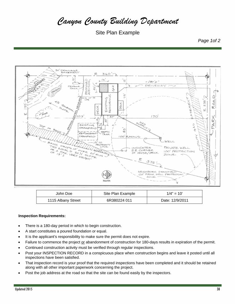
Canyon County Building Department Site Plan Example
Page 1of 2
John Doe Site Plan Example 1/4” = 10’
1115 Albany Street 6R380224 011 Date: 12/9/2011
Inspection Requirements:
There is a 180-day period in which to begin construction.
A start constitutes a poured foundation or equal.
It is the applicant’s responsibility to make sure the permit does not expire.
Failure to commence the project or abandonment of construction for 180-days results in expiration of the permit.
Continued construction activity must be verified through regular inspections.
Post your INSPECTION RECORD in a conspicuous place when construction begins and leave it posted until all inspections have been satisfied.
That inspection record is your proof that the required inspections have been completed and it should be retained along with all other important paperwork concerning the project.
Post the job address at the road so that the site can be found easily by the inspectors.

Updated 2015 39
Canyon County Building Department Site Plan Example
Page 2 of 2

Updated 2015 40
Canyon County Building Department Footings
Page 1 of 2
Note: 1. Footings over 4’ 0” high are required to be designed as retaining walls. Minimum concrete strength 2500 p.s.i. lap rebar min. 40 diameters at splices - secure with tie wire.
24”
min
.
24”
min
Footing with Stem Wall Footing at Door Opening

Updated 2015 41
Canyon County Building Department Footing / Floor
Page 2 of 2
24”
Notes: 1. 4 x 6 D.F. #2 Girders - Maximum 7’ span. 2. 4 x 4 D.F. #2 Post. 4 x 6 required at girder splices. 3. Decking must be covered with 3/8” plywood or type 2M particle board. 4. 4x post over 3’ high must be braced. 5. Refer to rebar requirement on following pages for requirement in footing. 6. Support insulation at 12” O.C. to hold tight to underside of floor deck. Do Not Compress. 7. Minimum concrete strength 2500 p.s.i. lap rebar min. 40 diameters at splices secure with tie wire.
R-20 Insulation as required when heated
Framing Connectors
Updated 2015 42
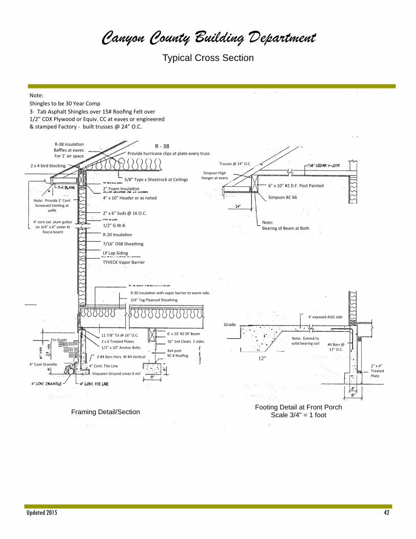
Canyon County Building Department Typical Cross Section
R ‐ 38
Note:
Shingles to be 30 Year Comp
3‐ Tab Asphalt Shingles over 15# Roofing Felt over 1/2” CDX Plywood or Equiv. CC at eaves or engineered & stamped Factory ‐ built trusses @ 24” O.C.
R‐38 insula on Baffles at eaves For 1’ air space
2 x 4 bird blocking
Note: Provide 2’ Cont Screened Ven ng at
soffit
4’ cont ext. alum gu er on 3/4” x 6” cedar tk
fascia board
Provide hurricane clips at plate every truss
5/8” Type x Sheetrock at Ceilings
2” Foam Insula on
4” x 10” Header or as noted
2” x 6” Suds @ 16 O.C.
1/2” G.W.B.
R‐20 Insula on
7/16” OSB Sheathing
LP Lap Siding
TYVECK Vapor Barrier
R‐30 Insula on with vapor barrier to warm side.
3/4” Tag Plywood Sheathing
Trusses @ 24” O.C.
Simpson High Hanger at every
6” x 10” #2 D.F. Post Painted Simpson BC 66
Note: Bearing of Beam at Both
Framing Detail/Section
Footing Detail at Front Porch Scale 3/4” = 1 foot
4’ exposed AGG slab
#4 Bars @ 12” O.C.
Note: Extend to solid bearing soil
Grade
12” 2” x 4” Treated Plate
Fin Grade 11 7/8” TJI @ 16” O.C.
2 x 6 Treated Plates
1/2” x 10” Anchor Bolts
2‐#4 Bars Horz. W #4 Ver cal
Visqueen Ground cover 6 mil
6’ x 10’ #2 DF Beam
16” 1x4 Cleats 2 sides
4x4 post 9C # Roofing
4” Cont. Tite Line 4” Cont Drain le
24
12”

Updated 2015 43
Canyon County Building Department Roof Framing Plan
Scale 1/4” = 1’0”

Updated 2015 44
Canyon County Building Department Sample Plan
Page 1 of 3
Notes:
1. Slab at garage floor shall be 4” thick with 6 ml black visqueen over compacted fill. 2. Foundation plates shall be bolted to foundation with not less than 1/2” steel bolts embedded 7” minimum into concrete spaced
not more than 12” apart with at least 2 bolts per piece. Washers are required. 3. See framing plan for steel requirements. 4. Foundation ventilation shall be 1/150 of under floor area and shall be vented by approved mechanical means or by openings in
exterior perimeter wall. Opening shall be located as close to corners as practical and arranged to provide cross ventilation on at least 2 sides. They shall be covered with corrosion-resistant wire mesh 1/4” openings.
5. Crawl space under floor shall be at least 18” and a minimum of 12” under bottom of girders. 6. Under floor area shall be provided with a minimum of 18” x 24” access hole. 7. Provide 6 ml black vapor barrier lapped a minimum of 6” at each joint and extend up to the foundation wall. 8. Dryer to be vented separately to outside. 9. Anchored veneer shall be supported on footing. It shall have an air space between veneer and sheathing. Anchor ties to be
corrosion resistant; 1 for each 2 sq. ft. Add weep holes and flashing.
24”

Updated 2015 45
Canyon County Building Department Sample Plan
Page 2 of 3
Notes: 1. Solid Fuel Stoves shall be installed in accordance with manufacturers instruction. 2. Dryer to be separately vented to outside. 3. Attic access to be readily accessible. Minimum size 22” x 30” with 30” unobstructed headroom. 4. Appliance installed in garage shall be located out of the normal path of vehicles or a means of protection shall be provided. Units
generating a spark of flame shall have pilots and burners 18” above the floor. 5. If the lid of the garage is used as a fire separation, layers of 5/8” type X G W B shall be applied to framing. 6. Handrails shall be provided on two side opening and continuous on one side only. Handrail shall be 34” above nosing of tread
and shall be continuous the full length of the stairs and the ends shall return to the wall or shall terminate in a newell post. 7. Maximum rise 7 3/4” minimum run 10” minimum width 36” minimum headroom 6’8”. 8. Handrail to be minimum 34” to 38” in height with balusters not over 4” apart.
Updated 2015 46
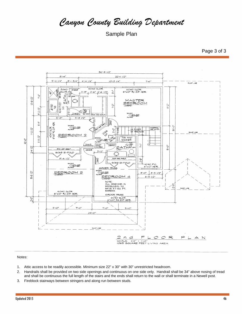
Canyon County Building Department Sample Plan
Page 3 of 3
Notes: 1. Attic access to be readily accessible. Minimum size 22” x 30” with 30” unrestricted headroom. 2. Handrails shall be provided on two side openings and continuous on one side only. Handrail shall be 34” above nosing of tread
and shall be continuous the full length of the stairs and the ends shall return to the wall or shall terminate in a Newell post. 3. Fireblock stairways between stringers and along run between studs.