A Recovery Boiler Recovered
7
Paper Number XXX A Recovery Boiler Recovered 2013 NZSEE Conference P.L. Dyer & R.D. Sharpe Beca AMEC Ltd., New Zealand J. Reid Carter Holt Harvey Ltd., Kawerau, New Zealand The 1987 Edgecumbe earthquake caused significant damage to industrial structures on the Tasman Pulp and Paper mill in Kawerau. More than 20 years later, the massive top- hung No.2 Recovery Boiler was ready for its final major maintenance refit which entailed replacement of about half its pressure parts. Owners Carter Holt Harvey had to decide on what associated seismic strengthening would be appropriate to bring the boiler and boilerhouse (the support structure) up to acceptable standards for the last 20 years of their life. Designed in the 1960s to much less than current seismic standards, the 1000-tonne boiler had swung violently in 1987 within the thermal expansion guides which retain it within the 1500 tonne 10-storey steel support structure. The guides were severely damaged as was some of the internal piping - but not sufficient for there to be an explosion. Similar recovery boilers suffered similar damage in the 2010 Chile earthquake. In the 2009 pre-Christchurch earthquake environment, the owner commissioned seismic assessments and concept studies that looked at both what the appropriate level of strengthening should be, and the possible benefits of retrofitting both the support structure and the guides. As a pro-active, long-term and prudent owner prepared to act in advance of government regulation in order to protect its personnel and assets, the company’s site engineering team determined the solution’s scope by working alongside its consultants. This paper describes the assessments, studies, and the multi-million dollar solutions which included the retrofit of the guides with lead-rubber bearings which will cocoon the boiler in any future shakes. 1 BACKGROUND 1.1 Original Design Designed in the 1960s to NZSS 1900 Chapter 8, the 1000-tonne top-hung boiler had swung violently in the 1987 Edgecumbe earthquake within its thermal expansion guides which separate it from the 1500 tonne, 50 metres high steel support structure. The guides, which were not specifically designed to be ductile, are on all four sides of the rectangular boiler at five levels, and allow the boiler to expand vertically up to 150 mm and 13 mm horizontally . The boiler is effectively a pendulum hanging within a cross-braced steel structure. Within the boiler, the many boiler tubes hang in loops from the top steam drums and are lightly restrained laterally. The external walls of the boiler are water-filled vertical tubes, and there are substantial external horizontal rectangular rings at the guide levels that stabilise the walls and transfer the guide forces to them. The boiler is fuelled by the wood residues in the syrup from the pulp cooking process, and the molten salts accumulate on the floor of the boiler from where they are “recovered” for re-use. If there were to be an accidental release of water (e.g., from earthquake damage) within the boiler, the molten salts would react with the water, causing the boiler to explode. One corner seam of the boiler is designed to split preferentially in the direction that has the least consequence, and there is an international history of such boilers failing this way.
Transcript of A Recovery Boiler Recovered

Paper Number XXX
A Recovery Boiler Recovered
2013 NZSEE Conference
P.L. Dyer & R.D. Sharpe
Beca AMEC Ltd., New Zealand
J. Reid
Carter Holt Harvey Ltd., Kawerau, New Zealand
The 1987 Edgecumbe earthquake caused significant damage to industrial structures on
the Tasman Pulp and Paper mill in Kawerau. More than 20 years later, the massive top-
hung No.2 Recovery Boiler was ready for its final major maintenance refit which entailed
replacement of about half its pressure parts. Owners Carter Holt Harvey had to decide on
what associated seismic strengthening would be appropriate to bring the boiler and
boilerhouse (the support structure) up to acceptable standards for the last 20 years of their
life. Designed in the 1960s to much less than current seismic standards, the 1000-tonne
boiler had swung violently in 1987 within the thermal expansion guides which retain it
within the 1500 tonne 10-storey steel support structure. The guides were severely
damaged as was some of the internal piping - but not sufficient for there to be an
explosion. Similar recovery boilers suffered similar damage in the 2010 Chile earthquake.
In the 2009 pre-Christchurch earthquake environment, the owner commissioned seismic
assessments and concept studies that looked at both what the appropriate level of
strengthening should be, and the possible benefits of retrofitting both the support structure
and the guides. As a pro-active, long-term and prudent owner prepared to act in advance
of government regulation in order to protect its personnel and assets, the company’s site
engineering team determined the solution’s scope by working alongside its consultants.
This paper describes the assessments, studies, and the multi-million dollar solutions
which included the retrofit of the guides with lead-rubber bearings which will cocoon the
boiler in any future shakes.
1 BACKGROUND
1.1 Original Design
Designed in the 1960s to NZSS 1900 Chapter 8, the 1000-tonne top-hung boiler had swung violently
in the 1987 Edgecumbe earthquake within its thermal expansion guides which separate it from the
1500 tonne, 50 metres high steel support structure.
The guides, which were not specifically designed to be ductile, are on all four sides of the rectangular
boiler at five levels, and allow the boiler to expand vertically up to 150 mm and 13 mm horizontally .
The boiler is effectively a pendulum hanging within a cross-braced steel structure. Within the boiler,
the many boiler tubes hang in loops from the top steam drums and are lightly restrained laterally. The
external walls of the boiler are water-filled vertical tubes, and there are substantial external horizontal
rectangular rings at the guide levels that stabilise the walls and transfer the guide forces to them. The
boiler is fuelled by the wood residues in the syrup from the pulp cooking process, and the molten salts
accumulate on the floor of the boiler from where they are “recovered” for re-use. If there were to be
an accidental release of water (e.g., from earthquake damage) within the boiler, the molten salts would
react with the water, causing the boiler to explode. One corner seam of the boiler is designed to split
preferentially in the direction that has the least consequence, and there is an international history of
such boilers failing this way.

2
1.2 1987 Earthquake Damage
The boiler suffered some damage to both the internal boiler tubes and their supports, and to the guides.
The boiler walls came very close to impacting the surrounding floors at the lower levels, but there was
not a significant loss of water containment. The intensity of shaking at the site was thought to be close
to the design levels current in 1987. Insurance considerations meant that the guides were returned to
their pre-earthquake conditions in order that production be resumed as quickly as possible.
Photos from 1987 of the structure, guide damage, and boiler inspection

3
Model of the support structure
1.3 Seismic assessment
In the 2009 pre-Christchurch earthquake environment, planning for the final 20-year major
replacement of its pressure parts was underway. Owners Carter Holt Harvey had to decide on what
associated seismic strengthening would be appropriate to bring this up to acceptable standards for its
last 20 years of life.
Checks during design of temporary works identified inconsistencies in the original seismic design. The
structure was found to be able to handle less than 25 % of the current code (NZS 1170.5) loadings for
a 50-year life. The structure could therefore be classified as “Earthquake Prone” (i.e., < 33%) in terms
of the regulations of the Building Act 2004.
Determining the seismic resilience of the complex boiler itself (and the replacement parts) was not
easy, particularly because the standard international designs commonly incorporate nominal/low
capacity seismic detailing. This encouraged following the concept of cocooning the suspended boiler
in a yielding guide system to limit the seismic loads that could be developed between boiler and
support structure.
2 STRENGTHENING ALTERNATIVES INVESTIGATED
A number of options were considered for improving the seismic performance of the boiler and its
support structure. Four were investigated analytically:
2.1 Conventional strengthening of the support structure
Building strengthened to 67 % of current code.
Boiler will also be subjected to 67 % of current code.
There were serious issues with strengthening the boiler to this load
level because of the significant work that would be required to
both mechanical and piping aspects of the boiler shell and
internals.
2.2 Conventional strengthening of building plus load-limiting
guides
Building strengthened to 67 % of current code.
Boiler will be subjected to lower seismic forces (i.e.,
within allowable stresses for a pressure vessel).

4
2.3 Base isolation of support structure
Issues with:
o Physical space required for installing lead-rubber
bearings
o Providing clearances
o Seismic loads attracted to gravity supports
o Modifications required to piping, spouts, blowers,
etc.
Boiler will be subjected to lower seismic forces (i.e., within
allowable stresses for a pressure vessel).
View of spout level at which base isolation was contemplated
Spout floor – with base isolation bearings Bearings clash with primary air ducting
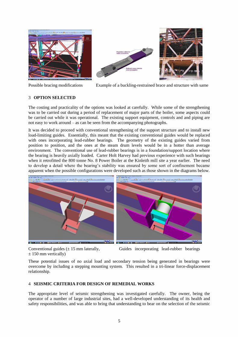
2.4 Bracing modifications or buckling-restrained braces
Increase the strength of the support structure
Make the support structure as ductile as possible
Issues with predicted magnitude of secondary moments and shears ruled this option out.
5
Possible bracing modifications Example of a buckling-restrained brace and structure with same
3 OPTION SELECTED
The costing and practicality of the options was looked at carefully. While some of the strengthening
was to be carried out during a period of replacement of major parts of the boiler, some aspects could
be carried out while it was operational. The existing support equipment, controls and and piping are
not easy to work around – as can be seen from the accompanying photographs.
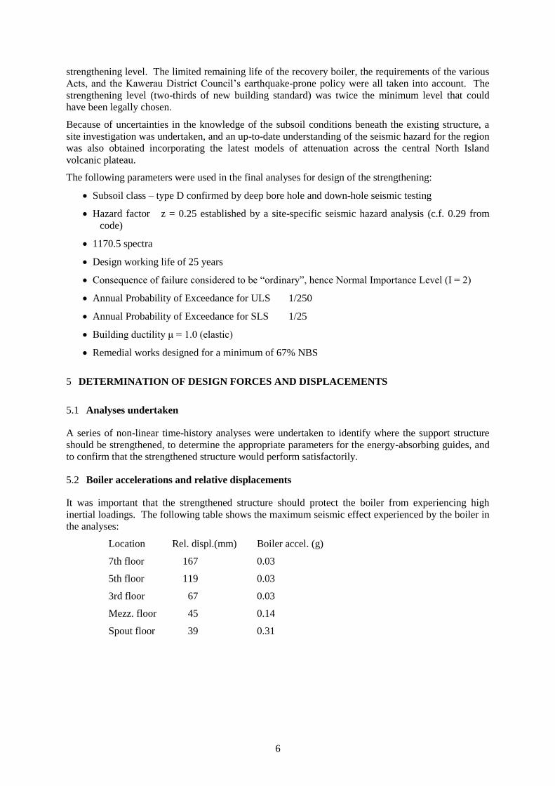
It was decided to proceed with conventional strengthening of the support structure and to install new
load-limiting guides. Essentially, this meant that the existing conventional guides would be replaced
with ones incorporating lead-rubber bearings. The geometry of the existing guides varied from
position to position, and the ones at the steam drum levels would be in a hotter than average
environment. The conventional use of lead-rubber bearings is in a foundation/support location where
the bearing is heavily axially loaded. Carter Holt Harvey had previous experience with such bearings
when it retrofitted the 800 tonne No. 8 Power Boiler at the Kinleith mill site a year earlier. The need
to develop a detail where the bearing’s stability was ensured by some sort of confinement became
apparent when the possible configurations were developed such as those shown in the diagrams below.
Conventional guides (± 15 mm laterally, Guides incorporating lead-rubber bearings
± 150 mm vertically)
These potential issues of no axial load and secondary tension being generated in bearings were
overcome by including a stepping mounting system. This resulted in a tri-linear force-displacement
relationship.
4 SEISMIC CRITERIA FOR DESIGN OF REMEDIAL WORKS
The appropriate level of seismic strengthening was investigated carefully. The owner, being the
operator of a number of large industrial sites, had a well-developed understanding of its health and
safety responsibilities, and was able to bring that understanding to bear on the selection of the seismic
6
strengthening level. The limited remaining life of the recovery boiler, the requirements of the various
Acts, and the Kawerau District Council’s earthquake-prone policy were all taken into account. The
strengthening level (two-thirds of new building standard) was twice the minimum level that could
have been legally chosen.
Because of uncertainties in the knowledge of the subsoil conditions beneath the existing structure, a
site investigation was undertaken, and an up-to-date understanding of the seismic hazard for the region
was also obtained incorporating the latest models of attenuation across the central North Island
volcanic plateau.
The following parameters were used in the final analyses for design of the strengthening:
Subsoil class – type D confirmed by deep bore hole and down-hole seismic testing
Hazard factor z = 0.25 established by a site-specific seismic hazard analysis (c.f. 0.29 from
code)
1170.5 spectra
Design working life of 25 years
Consequence of failure considered to be “ordinary”, hence Normal Importance Level (I = 2)
Annual Probability of Exceedance for ULS 1/250
Annual Probability of Exceedance for SLS 1/25
Building ductility μ = 1.0 (elastic)
Remedial works designed for a minimum of 67% NBS
5 DETERMINATION OF DESIGN FORCES AND DISPLACEMENTS
5.1 Analyses undertaken
A series of non-linear time-history analyses were undertaken to identify where the support structure
should be strengthened, to determine the appropriate parameters for the energy-absorbing guides, and
to confirm that the strengthened structure would perform satisfactorily.
5.2 Boiler accelerations and relative displacements
It was important that the strengthened structure should protect the boiler from experiencing high
inertial loadings. The following table shows the maximum seismic effect experienced by the boiler in
the analyses:
Location Rel. displ.(mm) Boiler accel. (g)
7th floor 167 0.03
5th floor 119 0.03
3rd floor 67 0.03
Mezz. floor 45 0.14
Spout floor 39 0.31

7
6 DETAILS OF STRENGTHENING
The extent of the structural strengthening can be gathered from the cost which was of the order of 10
million dollars. The opportunity was also taken to replace structural members which had corroded
after more than 40 years exposure to the process.
The manufacture of a few of the lead-rubber bearings was not without some problems because of their
unusual aspect ratio, and the light axial load on them. The supplier was eventually able to provide
bearings for the unusual operating conditions by modifying his normal manufacturing techniques.
Sample bearings were extensively tested as part of the design development, and all bearings
underwent full load testing before acceptance.
Measurement of actual working temperatures showed that they were in a range where there was no
concern.
The photo above shows one typical guide installation containing lead-rubber bearings. The diagram shows the
use of twin bearings to provide a stable energy-absorbing guide.
The photo above shows typical strengthening of a brace in the support structure.
7 SUMMARY
A large industrial structure and the process within have had their life extended in a manner which
exceeds the minimum seismic standards applicable. In a pre Christchurch earthquakes environment,
the owner was able to investigate a number of options and levels of strengthening to be in a position to
choose rationally a solution compatible with his health and safety policies and the prevailing
requirements under the Building Act. An innovative solution was developed to protect an industry-
standard boiler of low inherit seismic resilience in an economical manner. This was achieved by close
co-operation between the owner’s technical staff and his consultant engineers.