A Quick Course on Magnetic, Cable and Pipe Locating be coming from a power cable, a nearby pipe, or...
46
SCHONSTEDT INSTRUMENT COMPANY A Quick Course on Magnetic, Cable and Pipe Locating
Transcript of A Quick Course on Magnetic, Cable and Pipe Locating be coming from a power cable, a nearby pipe, or...
SCHONSTEDT INSTRUMENT COMPANY
A Quick Course onMagnetic, Cable and PipeLocating

© February 2003SCHONSTEDT INSTRUMENT COMPANY4 Edmond Road Kearneysville, WV 25430800-999-8280 304-725-1050 Fax: 304-725-1095Internet: www.schonstedt.com E-Mail: [email protected]

Table oof CContentsI. Cable and Pipe Locating BasicsApplying the Signal. . . . . . . . . . . . . . . . . . . . . . . . . . . . . 3
The Conductive Method . . . . . . . . . . . . . . . . . . . . . . . . . 4
The Inductive Method . . . . . . . . . . . . . . . . . . . . . . . . . . . 5
The Inductive Clamp Method . . . . . . . . . . . . . . . . . . . . . 6
Passive Power Frequencies . . . . . . . . . . . . . . . . . . . . . . 7
Trace Mode . . . . . . . . . . . . . . . . . . . . . . . . . . . . . . . . . . 7
Adjusting the Gain . . . . . . . . . . . . . . . . . . . . . . . . . . . . . 8
Sweeping . . . . . . . . . . . . . . . . . . . . . . . . . . . . . . . . . . . . 8
Tracing . . . . . . . . . . . . . . . . . . . . . . . . . . . . . . . . . . . . . . 9
2. Telephone Cable Locating TechniquesIntroduction. . . . . . . . . . . . . . . . . . . . . . . . . . . . . . . . . . 10
Applying Signal to Telephone Cables: . . . . . . . . . . . . . . 10
Inductive method . . . . . . . . . . . . . . . . . . . . . . . . . . . . . 10
Conductive Method . . . . . . . . . . . . . . . . . . . . . . . . . . . . 11
Inductive Clamp Method . . . . . . . . . . . . . . . . . . . . . . . . 12
Locating Slack Loops and Butt Splice . . . . . . . . . . . . . . 15
Locating Unknown Laterals . . . . . . . . . . . . . . . . . . . . . . 15
Locating Cables from Pedestals . . . . . . . . . . . . . . . . . . 17
Locating Service Drops. . . . . . . . . . . . . . . . . . . . . . . . . 18
Locating an Open End . . . . . . . . . . . . . . . . . . . . . . . . . 18
Fiber Optic Locating . . . . . . . . . . . . . . . . . . . . . . . . . . . 18
Can the Fiber Be Traced?. . . . . . . . . . . . . . . . . . . . . . . 18
Applying the Trace Signal . . . . . . . . . . . . . . . . . . . . . . . 19
Attaching at CO or Remote Terminal Office . . . . . . . . . . 19
Attaching at the Splice Point . . . . . . . . . . . . . . . . . . . . . 20
Tracing Fiber Optic Cable . . . . . . . . . . . . . . . . . . . . . . . 21
3. Power Cable Locating TechniquesApplying Signal to Power Cables . . . . . . . . . . . . . . . . . 22
Conductive Method . . . . . . . . . . . . . . . . . . . . . . . . 22
Applying Signal to the Transformer . . . . . . . . . . . . . . . . 22
Applying Signal at the Meter . . . . . . . . . . . . . . . . . . . . . 23
Applying Signal to a De-Energized Secondary . . . . . . . 23
Applying Signal to Power Cables:
Inductive Method . . . . . . . . . . . . . . . . . . . . . . . . . . 24
Inductive Clamp Method . . . . . . . . . . . . . . . . . . . . 24
Applying Signal to Primary Cables . . . . . . . . . . . . . . . . 24
Applying Signal to Secondary Cables . . . . . . . . . . . . . . 26
Identifying Slack Loops . . . . . . . . . . . . . . . . . . . . . . . . . 27
Identifying A Cable Open End . . . . . . . . . . . . . . . . . . . . 27
Locating Buried Streetlight Cables . . . . . . . . . . . . . . . . 28
4. CATV Cable Locating TechniquesApplying Signal to CATV Cables . . . . . . . . . . . . . . . . . . 29
Inductive Method . . . . . . . . . . . . . . . . . . . . . . . . . . 29
Conductive Method . . . . . . . . . . . . . . . . . . . . . . . . 30
Inductive Clamp Method . . . . . . . . . . . . . . . . . . . . 31
Locating Cable Slack Loops . . . . . . . . . . . . . . . . . . . . . 32
Locating CATV Cables from Pedestals . . . . . . . . . . . . . 32
5. Pipe Locating TechniquesApplying Signal to Pipe. . . . . . . . . . . . . . . . . . . . . . . . . 34
Inductive Method . . . . . . . . . . . . . . . . . . . . . . . . . 34
Conductive Method . . . . . . . . . . . . . . . . . . . . . . . . 35
Conductive Method on Tracer Wires. . . . . . . . . . . . 36
Inductive Clamp Method . . . . . . . . . . . . . . . . . . . . 37
6. Magnetic LocatingTheory of Operation . . . . . . . . . . . . . . . . . . . . . . . . . . . 39
Searching . . . . . . . . . . . . . . . . . . . . . . . . . . . . . . . . . . . 40
Pinpointing . . . . . . . . . . . . . . . . . . . . . . . . . . . . . . . . . . 40
Adjusting the Sensitivity . . . . . . . . . . . . . . . . . . . . . . . . 41
Strongly Magnetized Markers . . . . . . . . . . . . . . . . . . . . 41
Searching Areas Along a Chain Link Fence. . . . . . . . . . 42
Locating Metallic Pipe . . . . . . . . . . . . . . . . . . . . . . . . . . 43
Locating Objects In Areas of Clutter . . . . . . . . . . . . . . . 44
Things to Remember about Magnetic Locating . . . . . . . 44

Cable and Pipe Locating Basics
Applying the Signal
There are three methods of applying signal with a transmitter:
Conductive method
Inductive method
Inductive Clamp method
With any method of applying signal, frequency choice is important to get the "most" signalon the cable. Any signal applied to an insulated, buried cable or pipe leaks off to ground;as it gets farther away from the transmitter, the signal gets weaker and finally disappears. How fast it leaks off is determined by:
Cable diameter,
wet or dry soil conditions, and
signal frequency.
Since you do not have any control over the first two conditions, the Transmitter offersmore than one frequency choice:
Low (<1 kHz): These frequencies usually provide the most accurate locate in congestedareas (the lower the frequency, the better). They are best for tracing over long distancesand do not couple easily to other buried conductors. These frequencies are too low to beused with Inductive clamp or inductive methods and so the conductive method should beused.
Medium (1 kHz - 10 kHz): Medium frequencies are the most useful general-purposesignals. They allow the use of the Inductive clamp method. Although they will couple to
3
Chapter
1
other nearby cables, medium frequencies do not do so as strongly as high frequency.Medium frequencies travel less far than low frequencies but farther than the highfrequencies. They are best when the Inductive clamp method is used (when theconductive method cannot be used) and the tracing distance is one mile or less. Thesefrequencies may not be high enough to induce a strong signal on small diameter lines liketelecom cables.
High (10 kHz - 100 kHz): High frequencies attenuate over shorter distances than low ormedium frequencies. They travel well on small diameter conductors (CATV and Telecom).High frequencies will couple strongly to other nearby conductors. They work best withinductive clamp and induction methods. If the receive signal is weak at the beginning ofthe trace, try a higher frequency.
Very High (100 kHz and higher): These frequencies attenuate rapidly with distance andso are intended for shorter runs. They couple strongly to other nearby conductors and willcouple across non-conductive gaps such as cable breaks and insulated pipe joints. Theywork best with Inductive clamp and induction methods. Very high frequencies are best forsweeping a large area to locate all buried cables and pipes.
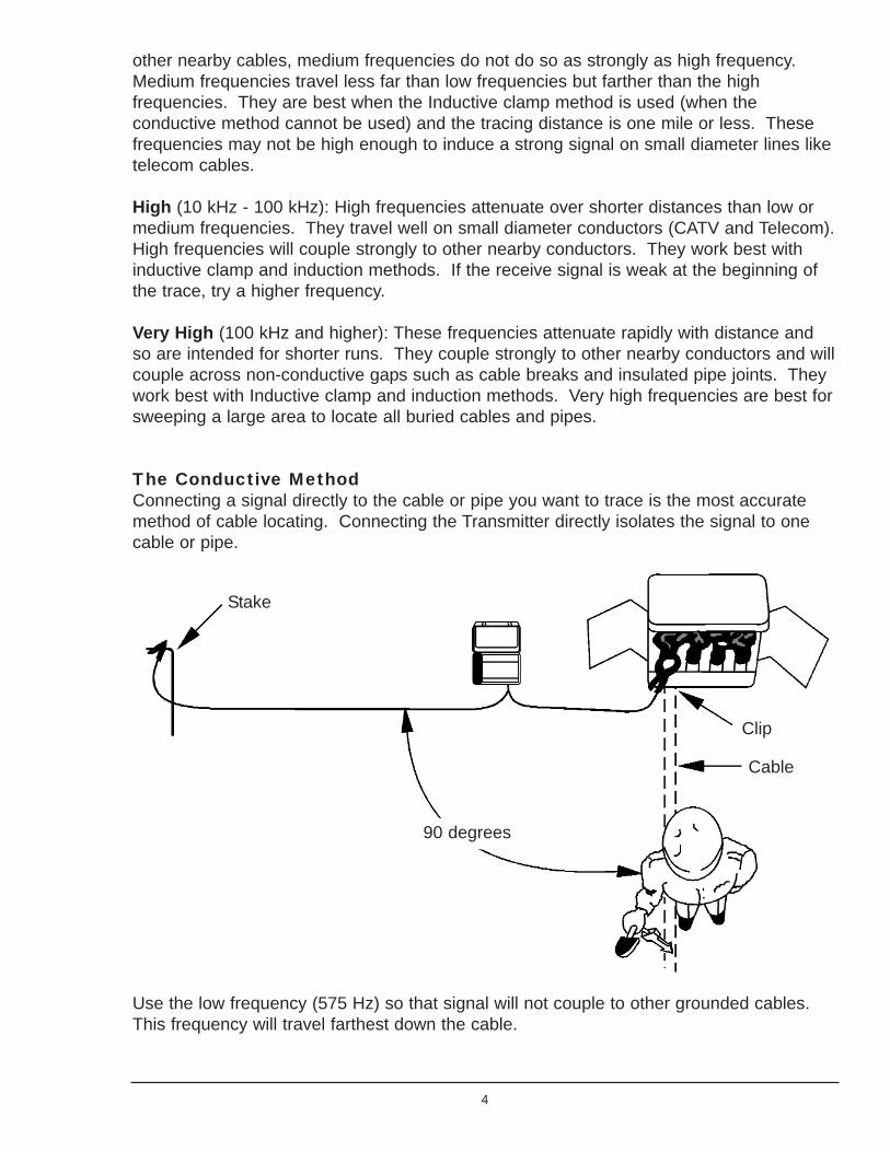
The Conductive MethodConnecting a signal directly to the cable or pipe you want to trace is the most accuratemethod of cable locating. Connecting the Transmitter directly isolates the signal to onecable or pipe.
Use the low frequency (575 Hz) so that signal will not couple to other grounded cables.This frequency will travel farthest down the cable.
4
Stake
90 degrees
Clip
Cable

Grounding can "make or break" a trace when you are using the Conductive method. TheTransmitter connects electrically to the cable or pipe and conducts a signal currentthrough it. The signal goes to ground at the far-end, and returns to the Transmitterthrough the ground stake. If the conductor is not well grounded at the far-end, or if theTransmitter connection to the ground stake is poor, the signal will be weak and notdetectable. The better the ground; the stronger the signal. Place the Transmitter groundstake as far from the far-end ground and as far from the trace path as possible. Ingeneral, this means placing the ground stake at a ninety-degree angle to the suspectedpath. If necessary, you can extend the ground lead with any insulated wire.
The Inductive Method
The simplest way to put signal on a buried cable or pipe is with the inductive method,where you merely set the Transmitter on the ground directly over the cable with the arrowparallel to the conductor. Of course, you have to have some idea where the conductor isburied. When the Transmitter is turned on, a signal current is induced into any parallelconductor within range. It is important to place the unit directly over the target cable withthe arrow parallel to the cable path, as shown above. The effectiveness of this methoddecreases rapidly if you place the Transmitter even 5 or 10 feet to either side of the path.
In congested situations where services such as gas or water pipes, cable TV, and lawn-watering control circuits are all buried nearby, you should not use the inductive methodbecause the signal will be applied to all nearby conductors causing confusion during thetrace.
5
Transmitter Receiver
The strength of the induced signal depends on three things:
The Transmitter frequency,
how well the conductor is grounded,
and how deep the conductor is buried.
When using the inductive method, the high frequencies (82 kHz or 455 kHz) should beused. Both of these frequencies will couple to the nearest conductors. Keep in mind that455 kHz will definitely put signal on conductors other than the one you are tracing. The Receiver can pick up signal from the Transmitter through the air from 40 feet away,even if no cable exists between them. For best results, keep the Receiver away from theTransmitter by at least that distance.
The conductor must be well grounded at both ends to produce a good locate. In allmethods, the better the ground to the conductor, the stronger the signal.
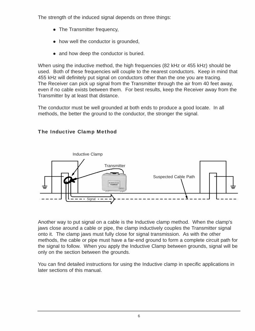
The Inductive Clamp Method
Another way to put signal on a cable is the Inductive clamp method. When the clamp'sjaws close around a cable or pipe, the clamp inductively couples the Transmitter signalonto it. The clamp jaws must fully close for signal transmission. As with the othermethods, the cable or pipe must have a far-end ground to form a complete circuit path forthe signal to follow. When you apply the Inductive Clamp between grounds, signal will beonly on the section between the grounds.
You can find detailed instructions for using the Inductive clamp in specific applications inlater sections of this manual.
6
Inductive Clamp
Transmitter
Suspected Cable Path
Signal
Passive Power Frequencies
In the Passive mode the transmitter does not produce any signal and the receiversearches for 50 or 60 Hz signals.
An energized cable carrying AC power produces a 50 or 60 Hz signal. Although these arerelatively low frequencies, they can still couple into other conductors buried nearby. Youcan detect the conductor because of the signal, but identification is impossible. The signalcould be coming from a power cable, a nearby pipe, or concrete reinforcing bars.However, the knowledge that these conductors exist is useful.
Most energized power cables are easy to detect unless they are designed to minimize thestrength of radiated signals so that the 'out' and 'return' current fields cancel each other,(this is the case with power cords we use everyday for lamps, computers, etc.). Thesecables are difficult to detect particularly with three-phase cables. The fundamentalfrequency normally cancels in a three-phase installation but the 9th harmonic of 60 Hz(540 Hz) reinforces, generating a stronger signal to trace. To locate 50 Hz power cables,the receiver is factory set to detect the 11th harmonic (550 Hz).
Trace Mode
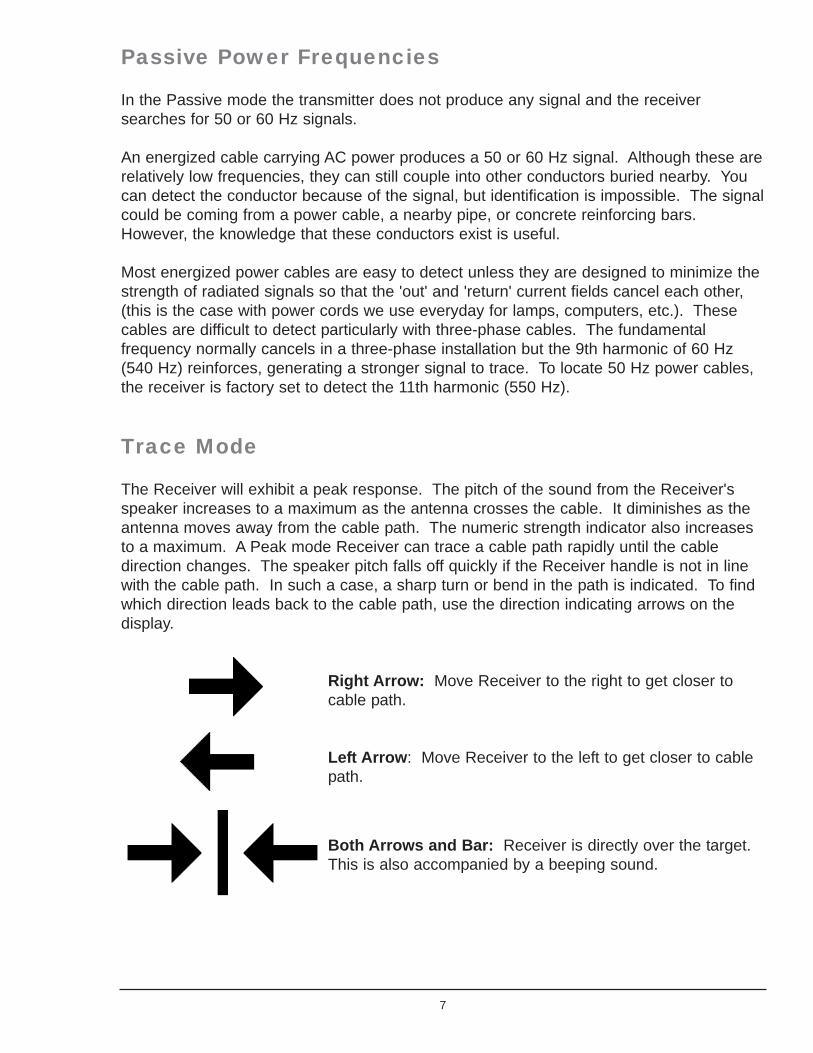
The Receiver will exhibit a peak response. The pitch of the sound from the Receiver'sspeaker increases to a maximum as the antenna crosses the cable. It diminishes as theantenna moves away from the cable path. The numeric strength indicator also increasesto a maximum. A Peak mode Receiver can trace a cable path rapidly until the cabledirection changes. The speaker pitch falls off quickly if the Receiver handle is not in linewith the cable path. In such a case, a sharp turn or bend in the path is indicated. To findwhich direction leads back to the cable path, use the direction indicating arrows on thedisplay.
Right Arrow: Move Receiver to the right to get closer tocable path.
Left Arrow: Move Receiver to the left to get closer to cablepath.
Both Arrows and Bar: Receiver is directly over the target.This is also accompanied by a beeping sound.
7
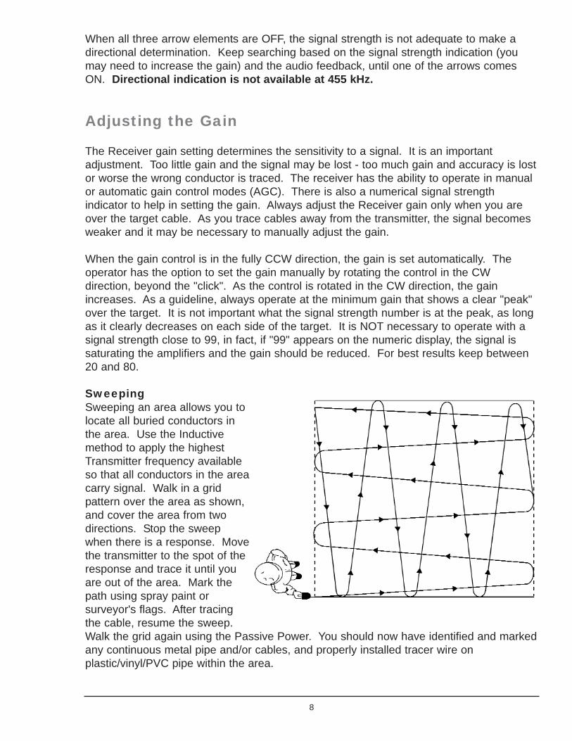
When all three arrow elements are OFF, the signal strength is not adequate to make adirectional determination. Keep searching based on the signal strength indication (youmay need to increase the gain) and the audio feedback, until one of the arrows comesON. Directional indication is not available at 455 kHz.
Adjusting the Gain
The Receiver gain setting determines the sensitivity to a signal. It is an importantadjustment. Too little gain and the signal may be lost - too much gain and accuracy is lostor worse the wrong conductor is traced. The receiver has the ability to operate in manualor automatic gain control modes (AGC). There is also a numerical signal strengthindicator to help in setting the gain. Always adjust the Receiver gain only when you areover the target cable. As you trace cables away from the transmitter, the signal becomesweaker and it may be necessary to manually adjust the gain.
When the gain control is in the fully CCW direction, the gain is set automatically. Theoperator has the option to set the gain manually by rotating the control in the CWdirection, beyond the "click". As the control is rotated in the CW direction, the gainincreases. As a guideline, always operate at the minimum gain that shows a clear "peak"over the target. It is not important what the signal strength number is at the peak, as longas it clearly decreases on each side of the target. It is NOT necessary to operate with asignal strength close to 99, in fact, if "99" appears on the numeric display, the signal issaturating the amplifiers and the gain should be reduced. For best results keep between20 and 80.
SweepingSweeping an area allows you tolocate all buried conductors inthe area. Use the Inductivemethod to apply the highestTransmitter frequency availableso that all conductors in the areacarry signal. Walk in a gridpattern over the area as shown,and cover the area from twodirections. Stop the sweepwhen there is a response. Movethe transmitter to the spot of theresponse and trace it until youare out of the area. Mark thepath using spray paint orsurveyor's flags. After tracingthe cable, resume the sweep.Walk the grid again using the Passive Power. You should now have identified and markedany continuous metal pipe and/or cables, and properly installed tracer wire onplastic/vinyl/PVC pipe within the area.
8

Tracing
To get the most accurate results when tracing a cable, signal should be isolated to theindividual cable. This means using either the Conductive or the Inductive clamp methodsof applying signal. If surface access is not possible, then use the induction method.Trace the cable at a slow walk while moving the Receiver in a side-to-side motion.Periodically mark the path. As tracing proceeds, remember that the most powerful signalis near the Transmitter. As the Receiver gets farther away from the Transmitter the signalstrength drops off. It will be necessary to readjust the gain periodically to be sure there isadequate signal for the Receiver to operate.
9

Telephone Cable Locating Techniques
Introduction
Read Chapter One of this manual to learn more general information about each of thefollowing signal application methods. The following paragraphs provide specific instructionon applying signal for telephone cable locating.
Applying Signal to Telephone Cables:
Inductive methodThe Inductive method broadcasts signal into an area. No access to the cable isnecessary. Use this only when no other buried conductors are present, or when locatingall buried services in a general area.
Place the Transmitter on the ground over the cable to be located. The Transmitter arrowshould be in line with the cable path, as shown above. Turn the Transmitter on and select
10
Chapter
2
Cable

the 82 kHz frequency. To be certain that the Transmitter is directly over the cable, use theReceiver to find a good clean peak about 50 feet down the cable. Move the transmitter tothis spot. Confirm that this is the target line by backtracking with the receiver to the firstsite of the transmitter. This procedure of leapfrogging the transmitter is also a goodmethod for extending the tracing range on electrically poor or leaky lines. If the Receiverhas trouble picking up the cable path, switch to the higher frequency.
Conductive MethodUse the conductive method for locating a specific cable among other cables, and to find acomplete break. You can use this method to trace a single cable or a line for distances upto 5,300 feet. A good electrical contact between the clip and the conductive portion of thetarget line is essential. You must remove any rust or paint to ensure a good electricalconnection. Electrical contact must also be made by driving the ground stake into theground as far off to the side of the line as the cable will permit. The low frequency 575 Hzsignal will not travel beyond a cable break and will not bleed off onto adjacent cables/linesand pipes.
The Conductive method requires access to the cable shield. Disconnect the shield bondat the near-end where the Transmitter is connected. Do not disconnect the far-end shieldbond since this supplies a far end ground.
Connect the Conductive connectors to the cable shield and to the ground stake. ConnectRed to the shield and black to the stake.
Place the ground stake as far away from the cable path as possible (90 degrees from thesuspected cable path). Never ground to water pipes or other services in the area. Thereturning signal on these services may mislead the trace.
11
Do NotRemovethis Bond
RemoveBond
Black
Red
Transmitter
Ground Stake
Insert the Conductive cable into the Transmitter jack. Turn the Transmitter on and choosethe lowest frequency to get the greatest signal distance down the cable. The trace signalwill be on the sheath between the Transmitter and the far end ground.
Observe the OUTPUT POWER LED for a rough indication of the circuit quality thetransmitter is hooked to:
If the LED is GREEN, the circuit is very good, which typically means the impedance isbelow 2 k ohms;
If the LED is alternating between GREEN & RED, the circuit is of medium quality, whichtypically means the impedance is between 2 and 4 k ohms.
If the LED is RED, the circuit is poor, which typically means the impedance is higher than4 k ohms.
If the indicator is RED or alternating GREEN & RED, you should try to improve theconnection (check the cables, the clips, the ground stake, wet the ground, clean rust ordirt, etc.). However, you may not be able to improve the connection. This does not meanthat you won't be able to locate. It just means that there is a smaller amount of currentcirculating in the circuit and you may have to increase your receiver gain, or not be able totrace the signal as far as you would with a higher current.
Inductive Clamp MethodThe Inductive clamp puts signal selectively on a cable by clamping around it. Thiseliminates the need to disconnect the cable. The Inductive clamp puts signal on a cablebetween grounds, so where you place it is important.
Insert the plug into the transmitter jack BEFORE TURNING THE POWER ON, open thejaws of the clamp and place it so that it completely encircles the desired cable. Make surethe clamp can fully closed.
12
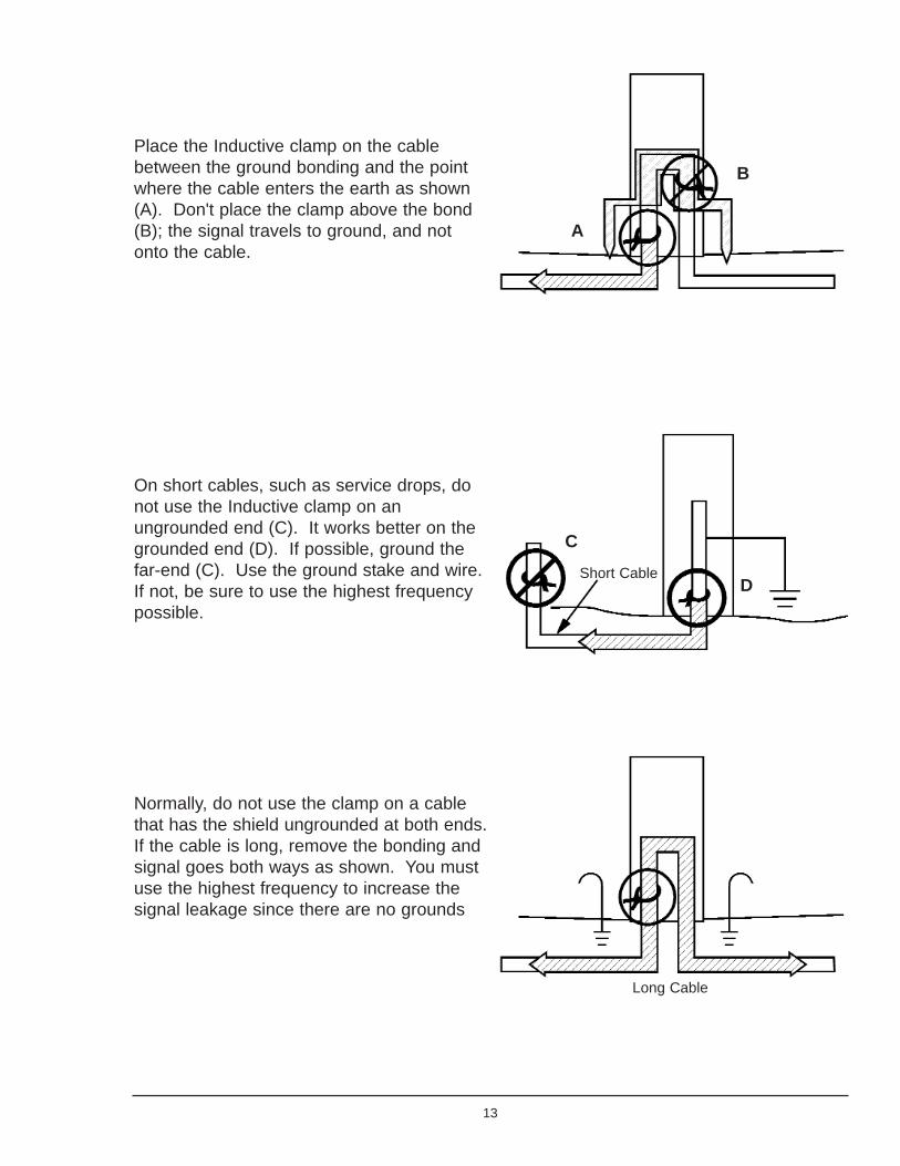
Place the Inductive clamp on the cablebetween the ground bonding and the pointwhere the cable enters the earth as shown(A). Don't place the clamp above the bond(B); the signal travels to ground, and notonto the cable.
On short cables, such as service drops, donot use the Inductive clamp on anungrounded end (C). It works better on thegrounded end (D). If possible, ground thefar-end (C). Use the ground stake and wire.If not, be sure to use the highest frequencypossible.
Normally, do not use the clamp on a cablethat has the shield ungrounded at both ends.If the cable is long, remove the bonding andsignal goes both ways as shown. You mustuse the highest frequency to increase thesignal leakage since there are no grounds
13
A
B
C
DShort Cable
Long Cable
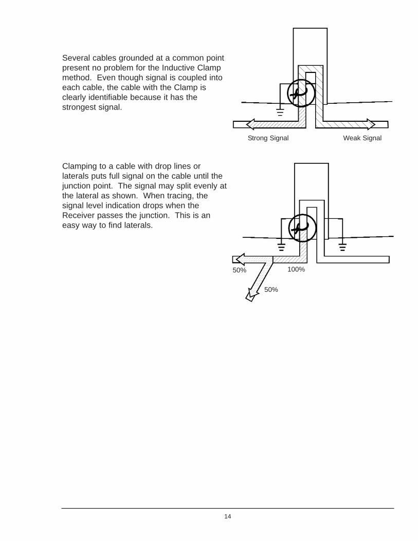
Several cables grounded at a common pointpresent no problem for the Inductive Clampmethod. Even though signal is coupled intoeach cable, the cable with the Clamp isclearly identifiable because it has thestrongest signal.
Clamping to a cable with drop lines orlaterals puts full signal on the cable until thejunction point. The signal may split evenly atthe lateral as shown. When tracing, thesignal level indication drops when theReceiver passes the junction. This is aneasy way to find laterals.
14
Strong Signal
100%
Weak Signal
50%
50%

Locating Slack Loops and Butt SpliceDuring normal tracing procedures, an unexplained loss of signal over a short distance mayindicate a buried slack loop or butt splice. Suspect laterals if the signal strength reducessignificantly after passing such a spot.
To identify the presence of these features along a cable path, first locate and mark thecable path near the abnormality. Find the strongest response over the marked cable pathand check the gain. Retrace the cable path with the Receiver held so the handle isperpendicular to (across) the cable path, as shown. The Receiver will have weak or non-existent response until it passes over a slack loop or butt splice, then the numeric signalstrength indicator will increase and the speaker will respond. Mark each response with an“X”. Whenever you encounter such a condition, check to see if an unknown lateral exists.
Locating Unknown Laterals
To check for unknown laterals that may radiate from a buried butt splice or closure,perform the procedure to locate butt splices or slack loops. Mark the spot of any detectedabnormalities (see above).
Go to the marked trace path and pinpoint the path about 10 to 25 feet from the markedspot. Find a peak response and check the gain. Hold the Receiver so that the display
15
Hold ReceiverAcross Cable Path
Butt Splice
Slack Loop

end of the handle points directly to the mark. Walk in a circle around the mark with theReceiver handle pointing to the mark.
The Receiver remains relatively quiet until it crosses a lateral or the actual cable path.Since there could be several laterals radiating from the closure, mark each occurrence ofsignal around the circle. After you locate each lateral, trace and mark its path.
16
MarkedTrace Path
Beep
Beep
Beep Receiver Pointsto “X”
MarkedButt Splice
10 to 25 Feet

Locating Cables from Pedestals
To locate a single cable path from a pedestal, follow these steps:
At the pedestal, apply tracing signal on the target cable using the Inductive Clampmethod. If the header in the pedestal is not grounded, use the ground stake and somewire to ground it.
Walk 10 to 25 feet away from the pedestal. Hold the Receiver so that the display end ofthe handle points directly to the pedestal. Start walking in a circle around the pedestalwith the Receiver always pointing toward the pedestal.
The Receiver remains relatively quiet until it crosses a cable. Stop when there is aresponse. Find the point of strongest signal and adjust the gain. Check the numericdisplay for signal strength. Remember the number and continue walking the circle. Asyou walk away from the cable, the signal drops. When you encounter another response,find the point of strongest signal and note the signal strength number. After completingthe circle, the cable with the greatest signal strength is the target cable.
17
Transmitter SignalApplied with Inductive Clamp Beep
Beep
BeepPoint Receiverto the Pedestal
Pedestal
10 to 25 FeetTransmitter

Locating Service Drops
When locating the path of a service drop from a house or other building, it is moreconvenient to apply signal at the house or building. Connect the Transmitter using theConductive method. Use the standard tracing techniques described earlier.
Locating an Open End
To locate an un-terminated or open end of a cable or drop, follow these steps.
If the cable is bonded to ground at the access point, connect the Transmitter using theInductive Clamp method. Otherwise, if the cable is not bonded to ground at the accesspoint, connect the Transmitter using the Conductive method. With either method, choosethe highest frequency available.
Trace the cable path. The receiver's response decreases suddenly at the site of the clearor severed end.
Fiber Optic Locating
Can the Fiber Be Traced?Fiber optic cables consist of fragile optical fibers encased in a strengthened outermember. The internal sheath of the cable may or may not be metallic. If it is not metallic,the manufacturer may include a metallic strength member (wire) within the sheath. Somefiber optic cables have no internal metal structure, in which case the contractor installingthe cable may pull an insulated wire through the underground duct with the fiber opticcable. If a metallic conductor is not in or next to the fiber optic cable, you cannot trace thecable path. You must then rely on site plans for physical location.
You normally find underground fiber optic cable installed in a duct, or a tube within theduct. The installation is normally made from a central office to a remote terminal office ordistribution point. There may be several splice points in hand holes or manholes alongthe route. Installation practices generally require that the fiber optic cable metallic sheathor strength member be grounded at the terminating ends. Bonding practices at the splicepoints vary by company. Therefore, the metallic strength member may or may not begrounded or may be grounded through a remotely actuated relay or a voltage transientsuppression device.
Some installations include a permanently installed rack-mounted transmitter that canselectively place a tracing signal on one of several fiber optic cables. If this transmitterproduces a 575 Hz or 512 Hz signal, you can trace the fiber optic cable using yourReceiver, if it is equipped with the 512 Hz sonde mode
18
Applying the Trace SignalIf the office installation includes a rack-mounted transmitter, check to see if your Receiverhas the same frequency and modulation as your receiver. To use the transmitter, attach itto the sheath or strength member of the fiber optic cable to be traced and turn it on. If thetransmitter frequency does not match the Receiver, or a rack-mounted transmitter is notavailable, attach your Transmitter at the CO or Remote Terminal Office, or at an interme-diate splice point.
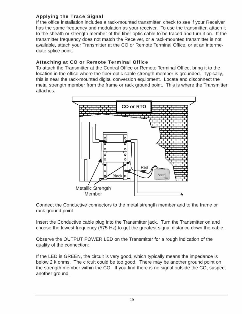
Attaching at CO or Remote Terminal OfficeTo attach the Transmitter at the Central Office or Remote Terminal Office, bring it to thelocation in the office where the fiber optic cable strength member is grounded. Typically,this is near the rack-mounted digital conversion equipment. Locate and disconnect themetal strength member from the frame or rack ground point. This is where the Transmitterattaches.
Connect the Conductive connectors to the metal strength member and to the frame orrack ground point.
Insert the Conductive cable plug into the Transmitter jack. Turn the Transmitter on andchoose the lowest frequency (575 Hz) to get the greatest signal distance down the cable.
Observe the OUTPUT POWER LED on the Transmitter for a rough indication of thequality of the connection:
If the LED is GREEN, the circuit is very good, which typically means the impedance isbelow 2 k ohms. The circuit could be too good. There may be another ground point onthe strength member within the CO. If you find there is no signal outside the CO, suspectanother ground.
19
Metallic StrengthMember
CO or RTO
Red
Black

If the LED is alternating between GREEN & RED, the circuit is of medium quality, whichtypically means the impedance is between 2K and 4K ohms. This may be an indication ofan open between this connection point and the ground at the terminating end or interme-diate splice points. A diminished signal will be placed on the fiber optic cable outside thebuilding.
If the LED is RED, the circuit is poor, which typically means the impedance is higher than4 k ohms. This is an indication of an open circuit or no far-end ground. Or maybe thewrong circuit completely. Very little signal will be placed on the fiber optic cable outsidethe building.
If the indicator is RED or alternating GREEN & RED, you should try to improve theconnection (check the cables, the clips, the frame ground, the far-end ground(s), cleanrust or dirt, etc.). However, you may not be able to improve the connection. This doesnot mean that you won't be able to locate. It just means that there is a smaller amount ofcurrent circulating in the circuit and you may have to increase your receiver gain, or not beable to trace the signal as far as you would with a higher current.
Attaching at the Splice PointTo attach the Transmitter at a field splice point, see if the splice case has one or twometal straps connected to ground. If so, you can attach the Transmitter at this location.
If the splice case has two straps, one of them most likely attaches to the metallic sheathor strength member on the incoming side and the other strap attaches to the outgoingside. This lets you connect the Transmitter to the incoming or outgoing side. The twostraps may also be connected inside the splice case.
Maximum tracing signal is obtained by disconnecting the bonding strap(s) from the groundpoint before attaching the Transmitter, but local practice may not allow this. In this case,the signal splits between the incoming cable, outgoing cable, and the ground point, thusreducing the tracing range.
20
Fiber Optic
OUT
Fiber Optic
INFiber Splices
MetallicStrength Member
Ground Straps
Ground Rod

Tracing Fiber Optic Cable
When tracing from a CO or Remote Terminal office, move to the cable's expected exitpoint outside the building. Search the area until a signal is received.
When tracing at a manhole or hand hole, hold the Receiver so that the display end of thehandle points directly towards the hole. Walk in a circle around the hole until a signal isdetected. Find a peak, check the gain, and trace the path of the cable.
When tracing a cable over a long distance, the signal strength decreases. This can becaused by the signal "bleeding" off into the earth due to capacitance or by additionalgrounds at splice points along the fiber optic cable. The "bleeding" effect causes agradual reduction in signal strength as the Receiver moves along the cable. The splicepoint ground causes an abrupt or distinct drop in signal because the signal is splitbetween the outgoing fiber optic cable and the local ground. These intermediate groundpoints can severely limit the tracing distance. This abrupt drop in signal is a goodindication of the presence of an earth ground at a splice point.
21
Fiber OpticCable with MetallicStrength Member
Splice Point
LocalEarth
Ground
100% 50%
Power Cable Locating Techniques
Applying Signal to Power Cables
(Passive 60 Hz Locating is explained in the Cable & Pipe Locating Basics - Chapter 1)
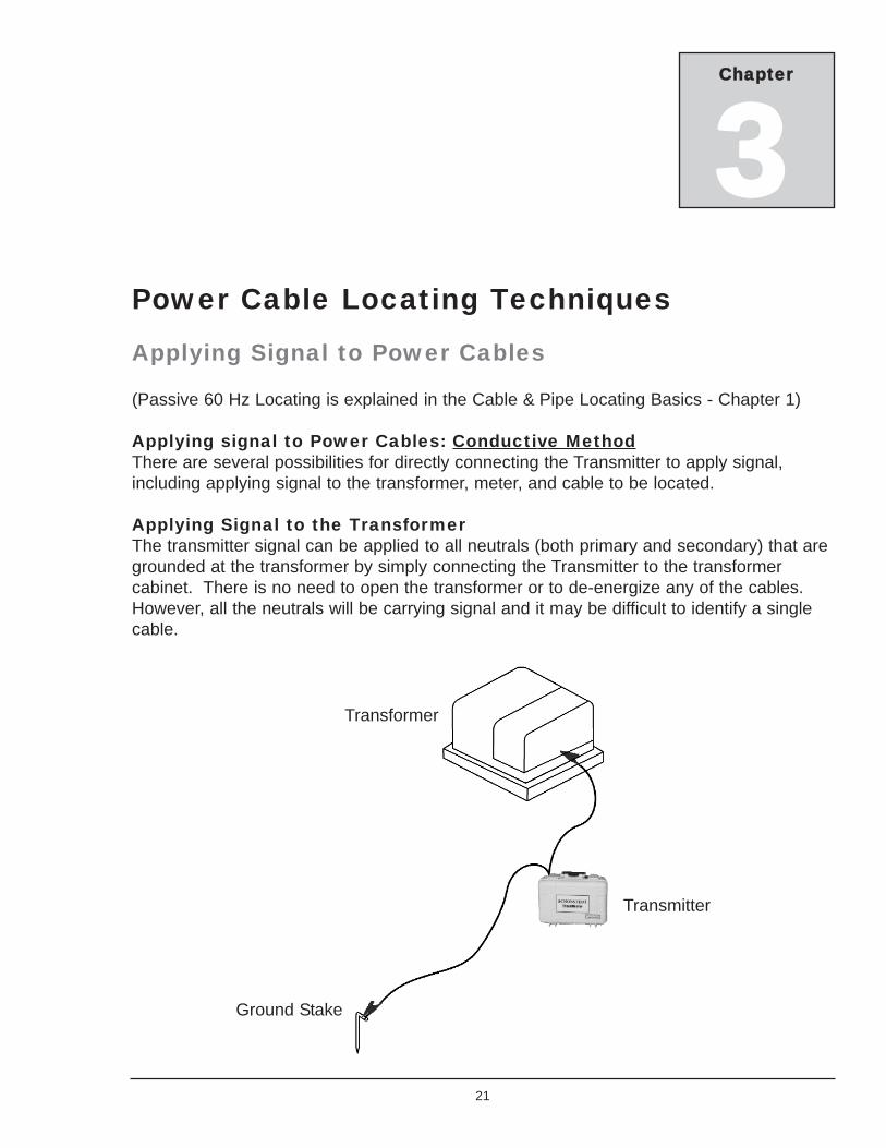
Applying signal to Power Cables: Conductive MethodThere are several possibilities for directly connecting the Transmitter to apply signal,including applying signal to the transformer, meter, and cable to be located.
Applying Signal to the TransformerThe transmitter signal can be applied to all neutrals (both primary and secondary) that aregrounded at the transformer by simply connecting the Transmitter to the transformercabinet. There is no need to open the transformer or to de-energize any of the cables.However, all the neutrals will be carrying signal and it may be difficult to identify a singlecable.
21
Chapter
3
Transformer
Ground Stake
Transmitter
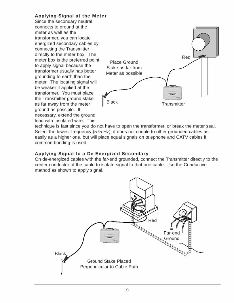
Applying Signal at the MeterSince the secondary neutralconnects to ground at themeter as well as thetransformer, you can locateenergized secondary cables byconnecting the Transmitterdirectly to the meter box. Themeter box is the preferred pointto apply signal because thetransformer usually has bettergrounding to earth than themeter. The locating signal willbe weaker if applied at thetransformer. You must placethe Transmitter ground stakeas far away from the meterground as possible. Ifnecessary, extend the groundlead with insulated wire. Thistechnique is fast since you do not have to open the transformer, or break the meter seal.Select the lowest frequency (575 Hz); it does not couple to other grounded cables aseasily as a higher one, but will place equal signals on telephone and CATV cables ifcommon bonding is used.
Applying Signal to a De-Energized SecondaryOn de-energized cables with the far-end grounded, connect the Transmitter directly to thecenter conductor of the cable to isolate signal to that one cable. Use the Conductivemethod as shown to apply signal.
23
Red
Black Transmitter
Place GroundStake as far fromMeter as possible
Ground Stake PlacedPerpendicular to Cable Path
Black
Red
Far-endGround
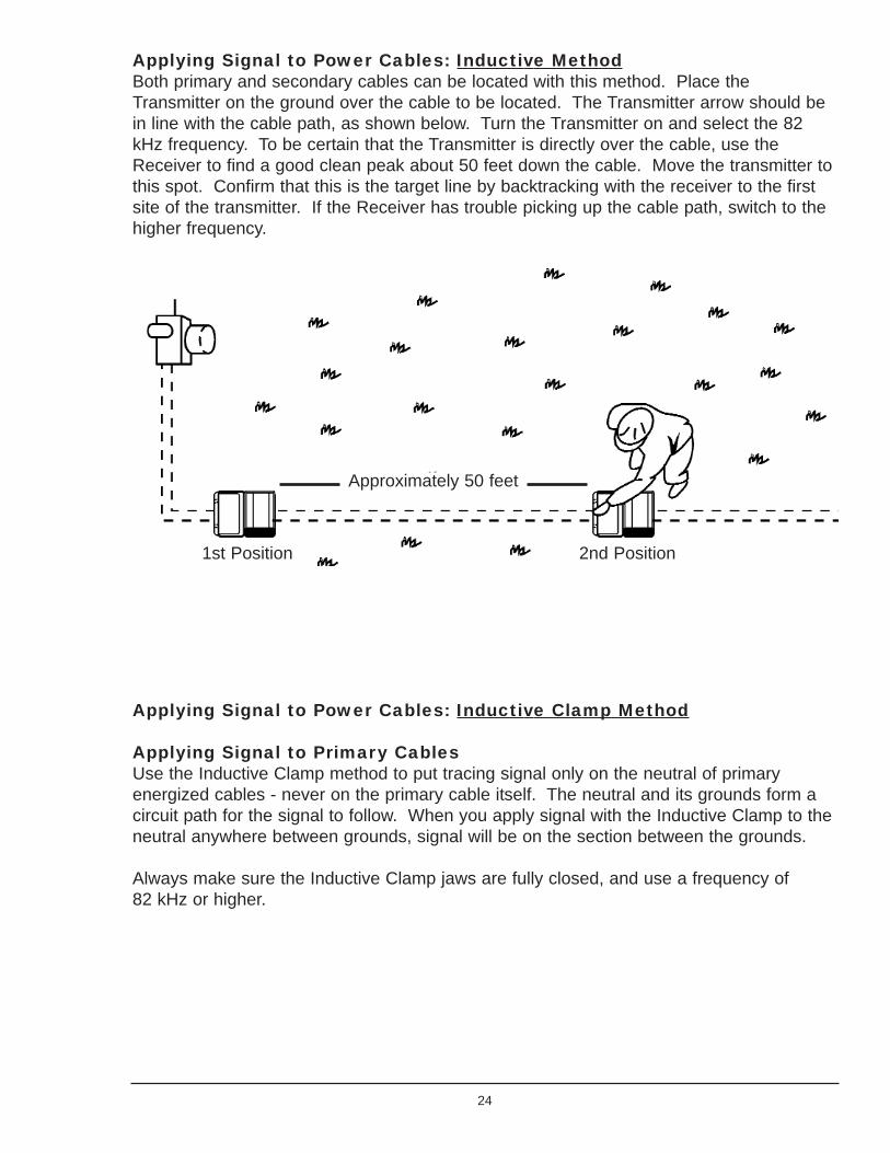
Applying Signal to Power Cables: Inductive MethodBoth primary and secondary cables can be located with this method. Place theTransmitter on the ground over the cable to be located. The Transmitter arrow should bein line with the cable path, as shown below. Turn the Transmitter on and select the 82kHz frequency. To be certain that the Transmitter is directly over the cable, use theReceiver to find a good clean peak about 50 feet down the cable. Move the transmitter tothis spot. Confirm that this is the target line by backtracking with the receiver to the firstsite of the transmitter. If the Receiver has trouble picking up the cable path, switch to thehigher frequency.
Applying Signal to Power Cables: Inductive Clamp Method
Applying Signal to Primary CablesUse the Inductive Clamp method to put tracing signal only on the neutral of primaryenergized cables - never on the primary cable itself. The neutral and its grounds form acircuit path for the signal to follow. When you apply signal with the Inductive Clamp to theneutral anywhere between grounds, signal will be on the section between the grounds.
Always make sure the Inductive Clamp jaws are fully closed, and use a frequency of 82 kHz or higher.
24
1st Position 2nd Position
Approximately 50 feet
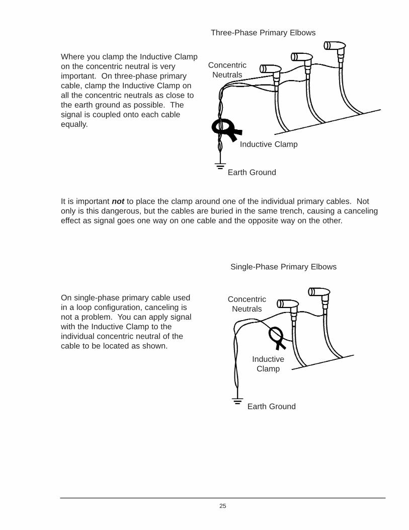
Where you clamp the Inductive Clampon the concentric neutral is veryimportant. On three-phase primarycable, clamp the Inductive Clamp onall the concentric neutrals as close tothe earth ground as possible. Thesignal is coupled onto each cableequally.
It is important not to place the clamp around one of the individual primary cables. Notonly is this dangerous, but the cables are buried in the same trench, causing a cancelingeffect as signal goes one way on one cable and the opposite way on the other.
On single-phase primary cable usedin a loop configuration, canceling isnot a problem. You can apply signalwith the Inductive Clamp to theindividual concentric neutral of thecable to be located as shown.
25
Three-Phase Primary Elbows
ConcentricNeutrals
Earth Ground
Inductive Clamp
Single-Phase Primary Elbows
ConcentricNeutrals
Earth Ground
InductiveClamp

Applying Signal to Secondary CablesTo locate secondary cables, the easiest accessto the neutral is at the meter box. There areseveral ways to put signal on the neutral. If theriser pipe is nonmetallic (usually PVC), clampthe Inductive Clamp around the pipe. The jawsof the clamp must fully close for signaltransmission. This may be impossible if the riseris flush with the mounting structure or biggerthan your clamp.
If this is the case and access is permitted, breakthe seal and open the meter box and clamparound the neutral in the box as shown.
Some meters may have an external ground wirefrom the meter box to an earth ground. Clamparound the wire as shown. This puts signal onthe neutral since the ground wire is connected tothe neutral in the meter box. Make sure youplace the Inductive Clamp above other utilitiesthat may be grounded at the ground rod, orsignal will be applied to them also.
26
GroundWire
GroundRod
NeutralConductor

Identifying Slack Loops
During normal tracing procedures, an unexplained loss of signal over a short distance mayindicate a buried slack loop. To identify the presence of this feature, first locate and markthe cable path for a short distance on both sides of the abnormality. Find the strongestresponse over the marked cable path and check the gain. Retrace the marked cable pathwith the Receiver held so the handle is perpendicular to (across) the cable path, asshown. The Receiver will have weak or non-existent response until it passes over theslack loop, then the numeric signal strength indicator will increase and the speaker willrespond.
Identifying A Cable Open End
It is sometimes necessary to locate the open end of a buried power cable. The cablecould have been severed or buried intentionally as in new construction. If the cable end isinsulated from earth ground, use the following technique.
If the cable is grounded at the access point, connect the Transmitter using the InductiveClamp method. Otherwise, if the cable is not grounded at the access point, connect theTransmitter using the Conductive method. With either method, choose the highestfrequency available.
Trace the cable path. The receiver's response decreases suddenly at the site of the clearor severed end.
27
Hold ReceiverAcross Cable Path
Slack Loop
Locating Buried Streetlight Cables
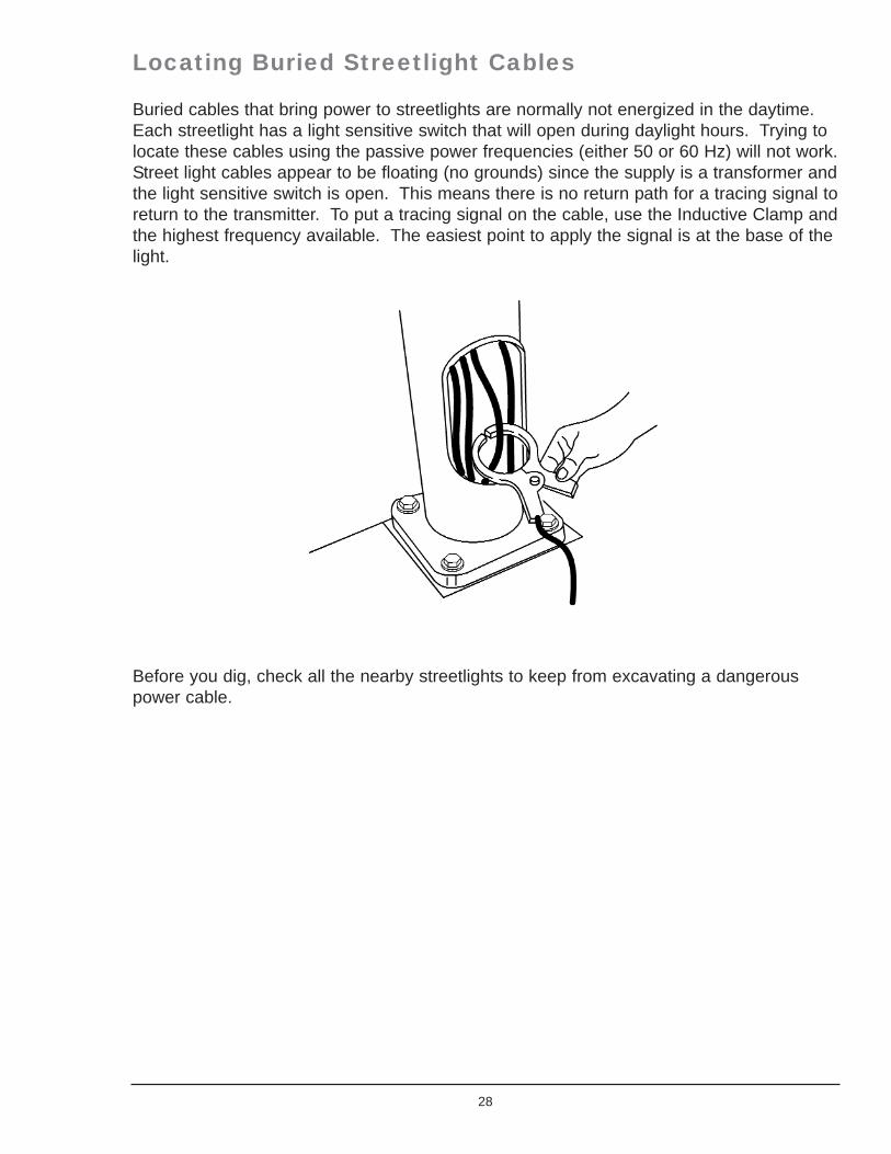
Buried cables that bring power to streetlights are normally not energized in the daytime.Each streetlight has a light sensitive switch that will open during daylight hours. Trying tolocate these cables using the passive power frequencies (either 50 or 60 Hz) will not work. Street light cables appear to be floating (no grounds) since the supply is a transformer andthe light sensitive switch is open. This means there is no return path for a tracing signal toreturn to the transmitter. To put a tracing signal on the cable, use the Inductive Clamp andthe highest frequency available. The easiest point to apply the signal is at the base of thelight.
Before you dig, check all the nearby streetlights to keep from excavating a dangerouspower cable.
28

CATV Cable Locating Techniques
Applying Signal to CATV Cables
Applying Signal to CATV Cables: Inductive Method
Place the Transmitter on the ground over the suspected cable path. Do not disconnecteither end of the cable as this provides grounds. The Transmitter arrow should be in linewith the cable path. Turn the Transmitter on and select the 82 kHz frequency. To becertain that the Transmitter is directly over the cable, trace the cable for about 50 feet.Find a spot that has a good clean peak. Move the transmitter to this spot (as shownbelow). Confirm that this is the target line by backtracking with the receiver to the first siteof the transmitter.
If the Receiver has trouble picking up the cable path, switch to a higher frequency.
29
Chapter
4
1st Position 2nd Position
Approximately 50 feet

Applying Signal to CATV Cables: Conductive MethodThe Conductive method requires access to the cable shield. Disconnect the cable wherethe Transmitter is to be connected. Do not disconnect at the far-end (subscriber'spremises) since this supplies a far-end ground. Perform the following steps to use theConductive method.
Connect the Conductive connectors to the cable shield and to the ground stake. ConnectRed to the shield and black to the stake.
Place the ground stake as far away from the cable path as possible (90 degrees from thesuspected cable path). Never ground to water pipes or other services in the area. Thereturning signal on these services may mislead the trace.
Insert the Conductive cable plug into the Transmitter jack. Turn the Transmitter on andchoose the lowest frequency to get the greatest signal distance down the cable. Thetrace signal will be on the sheath between the Transmitter and the far end ground.
Observe the OUTPUT POWER LED for a rough indication of the circuit quality thetransmitter is hooked to:
If the LED is GREEN, the circuit is very good, which typically means the impedance isbelow 2 k ohms.
If the LED is alternating between GREEN & RED, the circuit is of medium quality, whichtypically means the impedance is between 2K and 4K ohms.
If the LED is RED, the circuit is poor, which typically means the impedance is higher than4 k ohms.
30
Buried CATV Cable
Place Ground Rod 90 to Cable Path
Black Clip
Red Clip onthe Shield
Transmitter
Do Not Disconnect,Provides Ground
SubscriberPremises

If the indicator is RED or alternating GREEN & RED, you should try to improve theconnection (check the far-end ground, the cables, the clips, the ground stake, wet theground, clean rust, paint or dirt, etc.). However, you may not be able to improve theconnection. This does not mean that you won't be able to locate. It just means that thereis a smaller amount of current circulating in the circuit and you may have to increase yourreceiver gain, or not be able to trace the signal as far as you would with a higher current.
Applying Signal to CATV Cables: Inductive Clamp MethodThe Inductive Clamp is the easiest method to apply signal to a CATV cable. It is notnecessary to disconnect the cable. Open the clamp jaws and place them around thedesired cable. Make sure that the jaws close completely.
The Inductive Clamp couples the Transmitter signal onto the cable. The cable and itsshield grounds form a complete circuit path for the signal to follow. When the InductiveClamp is applied to the cable anywhere between earth grounds, signal is on the sectionbetween the grounds. Be aware that the shield may be grounded at the subscriber'spremises and also at a bridging amplifier on an aerial feeder line several blocks away.Everything between these grounds will carry signal. A removable ground (use the groundstake and some insulated wire) placed at a surface access point limits signal to that partof the cable between the grounds and keeps signal from going where it is not needed.Remove the ground when the job is finished.
31
Do NotDisconnect,
Provides Ground
Do NotDisconnect,
Provides Ground
Place Inductive Clamp here
Buried CATV Cable
Signal
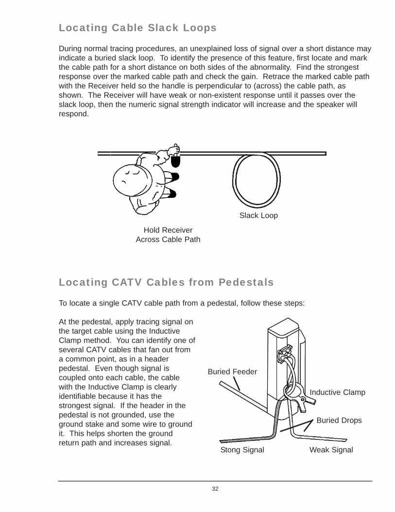
Locating Cable Slack Loops
During normal tracing procedures, an unexplained loss of signal over a short distance mayindicate a buried slack loop. To identify the presence of this feature, first locate and markthe cable path for a short distance on both sides of the abnormality. Find the strongestresponse over the marked cable path and check the gain. Retrace the marked cable pathwith the Receiver held so the handle is perpendicular to (across) the cable path, asshown. The Receiver will have weak or non-existent response until it passes over theslack loop, then the numeric signal strength indicator will increase and the speaker willrespond.
Locating CATV Cables from Pedestals
To locate a single CATV cable path from a pedestal, follow these steps:
At the pedestal, apply tracing signal onthe target cable using the InductiveClamp method. You can identify one ofseveral CATV cables that fan out froma common point, as in a headerpedestal. Even though signal iscoupled onto each cable, the cablewith the Inductive Clamp is clearlyidentifiable because it has thestrongest signal. If the header in thepedestal is not grounded, use theground stake and some wire to groundit. This helps shorten the groundreturn path and increases signal.
32
Hold ReceiverAcross Cable Path
Slack Loop
Stong Signal Weak Signal
Buried Drops
Inductive Clamp
Buried Feeder
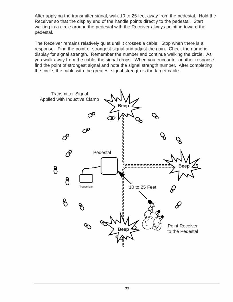
After applying the transmitter signal, walk 10 to 25 feet away from the pedestal. Hold theReceiver so that the display end of the handle points directly to the pedestal. Startwalking in a circle around the pedestal with the Receiver always pointing toward thepedestal.
The Receiver remains relatively quiet until it crosses a cable. Stop when there is aresponse. Find the point of strongest signal and adjust the gain. Check the numericdisplay for signal strength. Remember the number and continue walking the circle. Asyou walk away from the cable, the signal drops. When you encounter another response,find the point of strongest signal and note the signal strength number. After completingthe circle, the cable with the greatest signal strength is the target cable.
33
Transmitter SignalApplied with Inductive Clamp
Beep
Beep
BeepPoint Receiverto the Pedestal
Pedestal
10 to 25 FeetTransmitter

Pipe Locating Techniques
Applying Signal to Pipe
Applying Signal to Pipe: Inductive Method
Place the Transmitter on the ground over the suspected pipe path. The Transmitter arrowshould be in line with the path. Turn the Transmitter on and select the 82 kHz frequency.To be certain that the Transmitter is directly over the pipe, trace the pipe for about 50 feet.Find a spot that has a good clean peak. Move the transmitter to this spot (as shownbelow). Confirm that this is the target pipe by backtracking with the receiver to the firstsite of the transmitter. If the Receiver has trouble picking up the pipe path, switch to ahigher frequency.
This procedure of leapfrogging the transmitter is also a good method for extending thetracing range on pipe with insulated pipe joints or uncoated pipe that allows the signal toleak off rapidly.
34
Chapter
5
50 Feet
1st Position 2nd Position
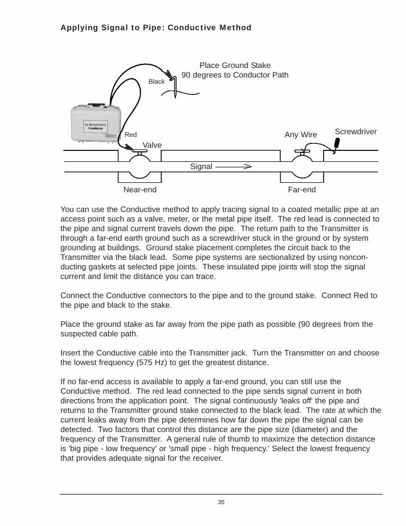
Applying Signal to Pipe: Conductive Method
You can use the Conductive method to apply tracing signal to a coated metallic pipe at anaccess point such as a valve, meter, or the metal pipe itself. The red lead is connected tothe pipe and signal current travels down the pipe. The return path to the Transmitter isthrough a far-end earth ground such as a screwdriver stuck in the ground or by systemgrounding at buildings. Ground stake placement completes the circuit back to theTransmitter via the black lead. Some pipe systems are sectionalized by using noncon-ducting gaskets at selected pipe joints. These insulated pipe joints will stop the signalcurrent and limit the distance you can trace.
Connect the Conductive connectors to the pipe and to the ground stake. Connect Red tothe pipe and black to the stake.
Place the ground stake as far away from the pipe path as possible (90 degrees from thesuspected cable path.
Insert the Conductive cable into the Transmitter jack. Turn the Transmitter on and choosethe lowest frequency (575 Hz) to get the greatest distance.
If no far-end access is available to apply a far-end ground, you can still use theConductive method. The red lead connected to the pipe sends signal current in bothdirections from the application point. The signal continuously 'leaks off' the pipe andreturns to the Transmitter ground stake connected to the black lead. The rate at which thecurrent leaks away from the pipe determines how far down the pipe the signal can bedetected. Two factors that control this distance are the pipe size (diameter) and thefrequency of the Transmitter. A general rule of thumb to maximize the detection distanceis 'big pipe - low frequency' or 'small pipe - high frequency.' Select the lowest frequencythat provides adequate signal for the receiver.
35
Black
Red Screwdriver
Far-endNear-end
Signal
ValveAny Wire
Place Ground Stake90 degrees to Conductor Path
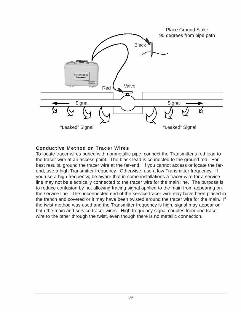
Conductive Method on Tracer WiresTo locate tracer wires buried with nonmetallic pipe, connect the Transmitter's red lead tothe tracer wire at an access point. The black lead is connected to the ground rod. Forbest results, ground the tracer wire at the far-end. If you cannot access or locate the far-end, use a high Transmitter frequency. Otherwise, use a low Transmitter frequency. Ifyou use a high frequency, be aware that in some installations a tracer wire for a serviceline may not be electrically connected to the tracer wire for the main line. The purpose isto reduce confusion by not allowing tracing signal applied to the main from appearing onthe service line. The unconnected end of the service tracer wire may have been placed inthe trench and covered or it may have been twisted around the tracer wire for the main. Ifthe twist method was used and the Transmitter frequency is high, signal may appear onboth the main and service tracer wires. High frequency signal couples from one tracerwire to the other through the twist, even though there is no metallic connection.
36
Place Ground Stake90 degrees from pipe path
Black
Red Valve
Signal
“Leaked” Signal
Signal
“Leaked” Signal

Apply Signal to Pipe: Inductive Clamp Method
The Inductive Clamp method works well onburied metallic pipe. You can detect signalon either side.
You can control the direction of the signalon the pipe by using the ground stake andsome wire to apply ground to that part ofthe pipe where signal is not needed, as shown. The external ground keeps the signal offthe pipe on that side of the clamp. Since the signal is being sent to only one part of thepipe, the magnitude is greater.
37
Signal
SignalSignal
Transmitter
Ground Rod
Far-endGround
Non-metallicService
Non-metallicService
Non-metallicMain
TwistedNon-electricalConnection
ElectricalConnection
Service TracerWire
Main TracerWire
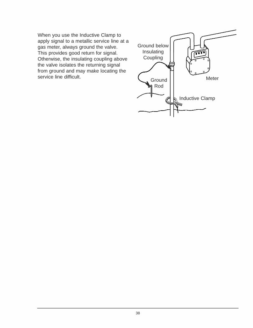
When you use the Inductive Clamp toapply signal to a metallic service line at agas meter, always ground the valve.This provides good return for signal.Otherwise, the insulating coupling abovethe valve isolates the returning signalfrom ground and may make locating theservice line difficult.
38
Inductive Clamp
MeterGroundRod
Ground belowInsulatingCoupling

Magnetic Locating
Theory of Operation
A magnet is a body having the properties of producing a magnetic field external to itself.This magnetic field is always bipolar to the object. The object will exhibit a north pole fromwhich the magnetic field emanates and a south pole where the field enters the object. Toavoid confusion, that part of the field near the North Pole is said to be positive and thatpart near the South Pole is negative. The shape of the field will surround the object andthe size of the field is determined by the strength of the magnet.
Ferrous (Iron) objects buried in the ground may have two types of magnetization thatproduce magnetic fields. One is the natural magnetization induced by the Earth'smagnetic field. This induced magnetization is weak, and always positive in the NorthernMagnetic Hemisphere. The other type of field is permanent magnetization that is artifi-cially imparted to ferrous objects to produce a strong, long lasting field. Its orientation isdetermined when the object ismagnetized.
Magnetic locators detect the magneticfield, either natural or artificial, aboutferrous objects. The locator has twosensors separated vertically about 8 to 20inches apart. The receiver will produce aresponse when the magnetic field strengthat the two sensors is different. Thisresponse may be a frequency change inan audio signal emitted from a speaker ormerely the presence of an audio response(no response when no field is detected).Some receivers also produce visualresponses on bar graphs or strengthindicators.
39
Chapter
6
Searching
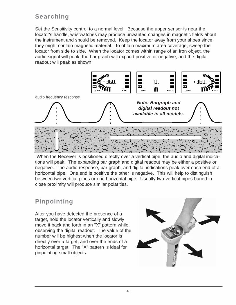
Set the Sensitivity control to a normal level. Because the upper sensor is near thelocator's handle, wristwatches may produce unwanted changes in magnetic fields aboutthe instrument and should be removed. Keep the locator away from your shoes sincethey might contain magnetic material. To obtain maximum area coverage, sweep thelocator from side to side. When the locator comes within range of an iron object, theaudio signal will peak, the bar graph will expand positive or negative, and the digitalreadout will peak as shown.
When the Receiver is positioned directly over a vertical pipe, the audio and digital indica-tions will peak. The expanding bar graph and digital readout may be either a positive ornegative. The audio response, bar graph, and digital indications peak over each end of ahorizontal pipe. One end is positive the other is negative. This will help to distinguishbetween two vertical pipes or one horizontal pipe. Usually two vertical pipes buried inclose proximity will produce similar polarities.
Pinpointing
After you have detected the presence of atarget, hold the locator vertically and slowlymove it back and forth in an "X" pattern whileobserving the digital readout. The value of thenumber will be highest when the locator isdirectly over a target, and over the ends of ahorizontal target. The "X" pattern is ideal forpinpointing small objects.
40
audio frequency responseNote: Bargraph anddigital readout not
available in all models.
Adjusting the Sensitivity
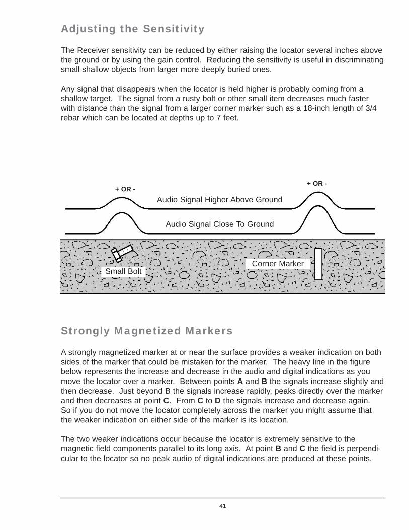
The Receiver sensitivity can be reduced by either raising the locator several inches abovethe ground or by using the gain control. Reducing the sensitivity is useful in discriminatingsmall shallow objects from larger more deeply buried ones.
Any signal that disappears when the locator is held higher is probably coming from ashallow target. The signal from a rusty bolt or other small item decreases much fasterwith distance than the signal from a larger corner marker such as a 18-inch length of 3/4rebar which can be located at depths up to 7 feet.
Strongly Magnetized Markers
A strongly magnetized marker at or near the surface provides a weaker indication on bothsides of the marker that could be mistaken for the marker. The heavy line in the figurebelow represents the increase and decrease in the audio and digital indications as youmove the locator over a marker. Between points A and B the signals increase slightly andthen decrease. Just beyond B the signals increase rapidly, peaks directly over the markerand then decreases at point C. From C to D the signals increase and decrease again.So if you do not move the locator completely across the marker you might assume thatthe weaker indication on either side of the marker is its location.
The two weaker indications occur because the locator is extremely sensitive to themagnetic field components parallel to its long axis. At point B and C the field is perpendi-cular to the locator so no peak audio of digital indications are produced at these points.
41
Small BoltCorner Marker
Audio Signal Higher Above Ground
Audio Signal Close To Ground
+ OR -+ OR -

Searching Areas Along a Chain Link Fence
Searching in the vicinity of achain link fence requires areduced Gain setting andalso control over theorientation of the locator.Position the locator horizon-tally with its long axisperpendicular to the fence.This ensures that the uppersensor is kept away from thefence. Perform the search byslowly moving the locatorforward along the fence whilealso moving it to the right andto the left. This techniqueallows you to search an areaseveral feet wide as youmove forward.
42
Audio Signal
A+ OR -
D+ OR -
C0
B0
+ OR -
IRON PIPE
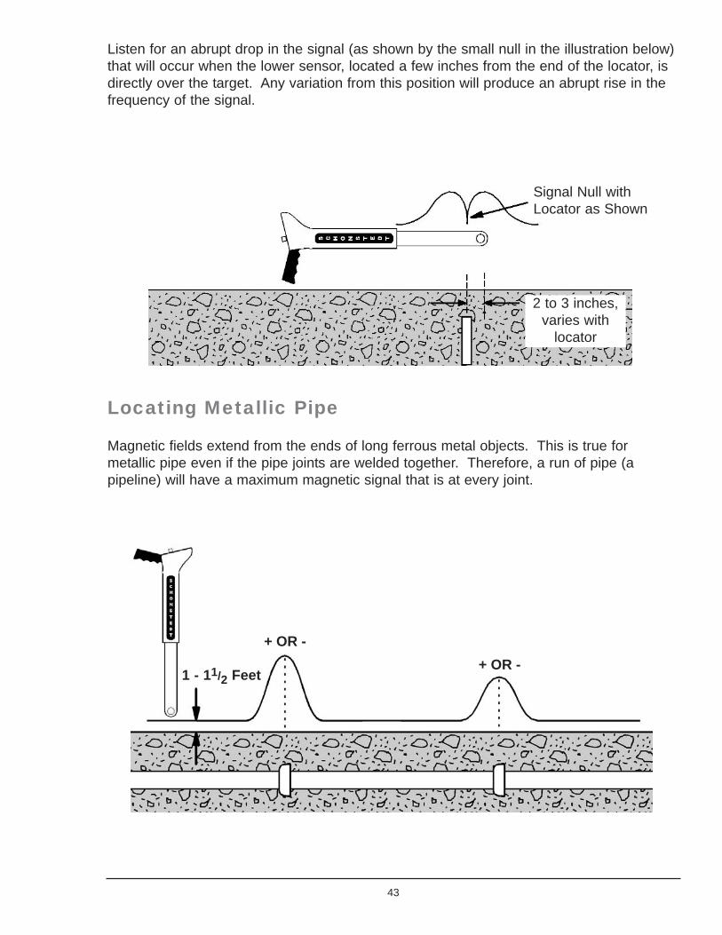
Listen for an abrupt drop in the signal (as shown by the small null in the illustration below)that will occur when the lower sensor, located a few inches from the end of the locator, isdirectly over the target. Any variation from this position will produce an abrupt rise in thefrequency of the signal.
Locating Metallic Pipe
Magnetic fields extend from the ends of long ferrous metal objects. This is true formetallic pipe even if the pipe joints are welded together. Therefore, a run of pipe (apipeline) will have a maximum magnetic signal that is at every joint.
43
Signal Null with Locator as Shown
2 to 3 inches,varies with
locator
+ OR -+ OR -
1 - 11/2 Feet
To magnetically trace a pipeline, set the gain control for maximum. Hold the locatorvertically approximately 1 to 1-1/2 feet above the surface. Walk along without turning ortilting the locator. Don't worry about pinpointing or being accurate. Temporarily mark thelocations where the maximum signal levels occur. Return to an area of maximum signalstrength and hold the locator several inches above the surface. The gain will probablyhave to be reduced during this second pass. Pinpoint and mark the places of maximumsignal. Looking then at your markers, you will see the run of the pipeline. Four-inch pipescan be located at depths up to 8 feet.
Locating Objects In Areas of ClutterIt is possible to pick up the magnetic field from a larger-mass target in the vicinity ofsmaller ferrous metals, by reducing the sensitivity so that the smaller targets are missed,and only the larger are detected. Also, physically raising or moving the locator away fromthe target reduces the sensitivity faster because the percentage of change in distance isgreater than the sensitivity settings on the locator. For example, a very large steel drummay be found under concrete rebar by raising the locator until the rebar disappears thensearching for the drum whose signals will be much stronger than the rebar that you havetuned out.
Remember that magnetic fields flow out of and into ferrous objects at the ends, therefore,steel rebar has its strongest signal at the end of every piece. Also, if the installer usedsteel wire to tie the bars together in a grid pattern, even the steel ties may be detectedcausing confusion as to where the exact end of a bar is located.
Things to Remember about Magnetic Locating
Used to find ferrous targets such as manhole covers, valve boxes, iron & steel pipes,marker magnets on plastic PVC pipe, surveyor's corner markers and PK nails, unexplodedordnance, and discarded weapons.
Use to find the joints in iron & steel pipe - even if they are welded together.
Use to find septic tanks (the handles), buried waste drums and canisters.
Can detect energized (current flowing) 50/60 cycle power lines with a distinctive "warbling"sound.
Can be used to find targets under snow or water. You must keep the electronic unit out ofthe water.
44

Properly performed, magnetic locating can be so accurate as to detect a "PK" 1-1/2" nailused in survey marking up to 18" under asphalt, and pinpoint the spot so that you couldhit the nail with a ½" drill.
Magnetic locators do not respond to non-ferrous materials such as gold, silver, copper,brass, aluminum, or plastic.
45